EP2022706A2 - Verdeckte Stützstruktur - Google Patents
Verdeckte Stützstruktur Download PDFInfo
- Publication number
- EP2022706A2 EP2022706A2 EP08013945A EP08013945A EP2022706A2 EP 2022706 A2 EP2022706 A2 EP 2022706A2 EP 08013945 A EP08013945 A EP 08013945A EP 08013945 A EP08013945 A EP 08013945A EP 2022706 A2 EP2022706 A2 EP 2022706A2
- Authority
- EP
- European Patent Office
- Prior art keywords
- under
- dash
- cover member
- support structure
- insulator
- Prior art date
- Legal status (The legal status is an assumption and is not a legal conclusion. Google has not performed a legal analysis and makes no representation as to the accuracy of the status listed.)
- Granted
Links
Images


Classifications
-
- B—PERFORMING OPERATIONS; TRANSPORTING
- B62—LAND VEHICLES FOR TRAVELLING OTHERWISE THAN ON RAILS
- B62D—MOTOR VEHICLES; TRAILERS
- B62D25/00—Superstructure or monocoque structure sub-units; Parts or details thereof not otherwise provided for
- B62D25/08—Front or rear portions
- B62D25/14—Dashboards as superstructure sub-units
- B62D25/142—Dashboards as superstructure sub-units having ventilation channels incorporated therein
-
- B—PERFORMING OPERATIONS; TRANSPORTING
- B60—VEHICLES IN GENERAL
- B60K—ARRANGEMENT OR MOUNTING OF PROPULSION UNITS OR OF TRANSMISSIONS IN VEHICLES; ARRANGEMENT OR MOUNTING OF PLURAL DIVERSE PRIME-MOVERS IN VEHICLES; AUXILIARY DRIVES FOR VEHICLES; INSTRUMENTATION OR DASHBOARDS FOR VEHICLES; ARRANGEMENTS IN CONNECTION WITH COOLING, AIR INTAKE, GAS EXHAUST OR FUEL SUPPLY OF PROPULSION UNITS IN VEHICLES
- B60K37/00—Dashboards
-
- B—PERFORMING OPERATIONS; TRANSPORTING
- B60—VEHICLES IN GENERAL
- B60R—VEHICLES, VEHICLE FITTINGS, OR VEHICLE PARTS, NOT OTHERWISE PROVIDED FOR
- B60R13/00—Elements for body-finishing, identifying, or decorating; Arrangements or adaptations for advertising purposes
- B60R13/08—Insulating elements, e.g. for sound insulation
- B60R13/0815—Acoustic or thermal insulation of passenger compartments
- B60R13/083—Acoustic or thermal insulation of passenger compartments for fire walls or floors
-
- B—PERFORMING OPERATIONS; TRANSPORTING
- B62—LAND VEHICLES FOR TRAVELLING OTHERWISE THAN ON RAILS
- B62D—MOTOR VEHICLES; TRAILERS
- B62D25/00—Superstructure or monocoque structure sub-units; Parts or details thereof not otherwise provided for
- B62D25/08—Front or rear portions
- B62D25/14—Dashboards as superstructure sub-units
- B62D25/145—Dashboards as superstructure sub-units having a crossbeam incorporated therein
Definitions
- Japanese Patent Application Publication No. 2004-268865 discloses an under-cover support structure for supporting an under cover member that is bridged between a dash panel and an instrument panel to cover the lower side of the instrument panel.
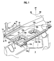
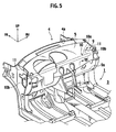
- the vehicle body 1 of the automobile includes an engine room 2 for housing an engine (not shown) therein, and a passenger compartment 3 located on the rear side in the front-rear direction of the vehicle, which serves as a vehicle cabin for passengers to be seated in.
- a dash panel 4 is provided between the engine room 2 and the passenger compartment 3, and defines the engine room 2 and the passenger compartment 3.
- a dash insulator 5 serving as a sound-absorbing member is adhered to a surface 4a of the dash panel 4 on a side of the vehicle cabin (hereinafter, simply referred to as "cabin-side surface 4a").
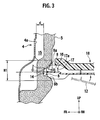
- the recessed portion 6 is a recess that extends approximately horizontally in the vehicle-width direction, and that substantially has a shape of a slotted hole when seen from the front thereof.
- the recessed portion 6 includes a bottom portion 7 having an elongated narrow shape, and a guide slope portion 8 formed around the periphery of the bottom portion 7.
- the guide slope portion 8 has a curved surface whose angle of inclination ⁇ gradually increases to a right angle as the measuring point of the angle of inclination ⁇ moves from the periphery of the recessed portion 6 to the bottom portion 7.
- the hollow portion 15 is a gap having a fixed width d that is formed between portions of the dash insulator 5 and the dash panel 4 above the recessed portion 6.
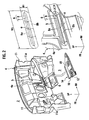
- a steering member 10 for supporting a steering column (not shown) is provided inside the instrument panel 9 so as to extend in the vehicle-width direction.
- the dash panel 4 is provided, at both ends thereof in the vehicle-width direction, with a pair of inner-side panels 11 each integrally extending rearward from the end of the dash panel 4.
- the right and left side brackets 10b of the steering member 10 are fixedly attached to inner surfaces 11a of the inner side panels 11, respectively. Thereby, the steering member 10 is fixed to the vehicle body 1.
- An H-bag-side fixing arm or a central fixing arm 10c is provided on the main body 10a of the steering member 10 so as to extend downward from the proximity of the center of the main body 10a in the vehicle-width direction.
- a side-panel-side fixing arm 10d is integrally formed to extend from the side bracket 10b on the right side of the vehicle.
- Bolt holes 10g and 10h are formed on a seating face 10e of the H-bag-side fixing arm 10c and a seating face 10f of the side-panel-side fixing arm 10d, respectively, as shown in Figs. 6 and 7 , by means of hole-boring process.
- Each of the seating faces is formed approximately perpendicular to but slightly inclined rearward with respect to a virtual plain including the long axis of the recessed portion 6 and the center of the corresponding bolt hole.
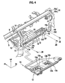
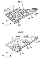
- an under cover member 12 is bridged to cover the lower side of the instrument panel 9 (see Fig. 8 ).
- Duct insertion openings 12a and 12b are formed in the sound insulation plate 13 (see Fig. 12 ).
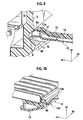
- a press-fit end portion 14 on the side of the dash insulator (hereinafter, referred to as a dash-insulator-side press-fit end portion 14), which is to be press-fitted into the recessed portion 6 formed in the dash insulator 5, is formed at the forward edge portion of the sound insulation plate 13 (see Figs. 8 and 11 ).
- a plurality of perpendicular ribs 16 are provided at regular intervals, along the forward edge of the sound insulation plate 13 of the under cover member 12, the perpendicular ribs 16 each being perpendicular to the upper or lower surface of the sound insulation plate 13.
- Each of the perpendicular ribs 16 is formed in a standing manner to extend from the upper or lower surface of the forward edge of the sound insulation plate 13, and is formed in a plain plate shape having a normal vector almost parallel to the vehicle-width direction or the forward edge of the sound insulation plate 13.
- each of the perpendicular ribs 16 has an R-shape at the forward edge thereof, or an R-shape extending from the forward edge thereof to the upper or lower edge thereof.
- reinforcing ribs 17 are provided on at least one of the upper and lower surfaces of the sound insulation plate 13, to connect each perpendicular rib 16.
- the reinforcing ribs 17 are perpendicular to the upper or lower surfaces of the sound insulation plate 13, and are extended approximately parallel to the vehicle-width direction or the forward edge of the sound insulation plate 13.
- an engaging blade 13b in a horizontal plate shape having a predetermined length in the vehicle-width direction is formed integrally at the rearward edge portion (cabin-side side edge) 13a of the sound insulation plate 13, as shown in Figs. 8 and 10 .
- the engaging blade 13b is extended rearward and has its rearward edge extending along the vehicle-width direction.
- the engaging blade 13b is placed on the forward edge 9a of the lower edge portion of the instrument panel 9 from above in an overlapping manner, and is engaged with the forward edge 9a serving as a rear supporting portion. Specifically, the rear supporting portion is engaged with the rearward edge portion 13a of the under cover member 12 in the vertical direction approximately perpendicular to the direction of the press-fitting of the under cover member 12.
- right and left fixing pieces 13c and 13d are formed, on the right and left outer sides of the engaging blade 13b, to protrude from the rearward edge portion 13a of the under cover member 12.
- Each of the fixing pieces 13c and 13d extends upward approximately perpendicular to but slightly inclined rearward with respect to the major surface of the sound insulation plate 13 of the under cover member 12.
- a duct insulator member 18 is set to cover the upper-surface side thereof, as shown in Fig. 12 .
- the duct insulator member 18 is configured to be positioned between the under cover member 12 and a duct member 19, which is an air conditioner, after the under cover member 12 is fitted.
- duct insertion openings 18a and 18b into which parts of the duct member 19 are inserted, are formed on the duct insulator member 18 at positions corresponding to the duct insertion openings 12a and 12b.
- a side-panel-side fixing piece 19a of the duct member 19 is fixed to a duct fixing face 10i of the side-panel-side fixing arm 10d with another bolt member 20, as shown in Figs. 4 and 7 .
- the steering member 10 as the one shown in Fig. 5 is fixed between the right and left inner side panels 11 shown in Fig. 2 , and the instrument panel 9 is thereby mounted on the cabin-side surface 4a of the dash panel 4 of the vehicle body 1.
- the air conditioner duct member 19 is attached to the instrument panel 9 in advance, as shown in Fig. 4 .
- the dash-insulator-side press-fit end portion 14 of the under cover member 12 is press-fitted into the recessed portion 6, which is formed in the dash insulator 5 adhered to the dash panel 4, from rear to front in a direction approximately parallel to the vehicle front-rear direction, as indicated by an arrow in Fig. 4 .
- the guide slope portion 8 is formed in the periphery of the recessed portion 6. Accordingly, the dash-insulator-side press-fit end portion 14 slides on and is guided by the guide slope portion 8 when being press-fitted, and is consequently aligned to the center O of the bottom portion 7 of the recessed portion 6. Thereby, the dash-insulator-side press-fit end portion 14 falls into a desired fitting position.
- the press-fit end portion 14 can be fitted into the desired fitting position due to the sliding guide function of the guide slope portion 8, as long as the inserting position of the press-fit end portion 14 remains within the range inside the outer peripheral edge of the guide slope portion 8 of H1 in height and W1 in width.
- the use of guide slope portion 8 makes the attachment of the under cover member 12 easier.
- the duct insulator member 18 is adhered to the upper-surface side of the under cover member 12. Accordingly, when the under cover member 12 is rotated to the position in which the sound insulation board 13 takes an approximately horizontal position, the duct insulator member 18 results in being positioned along the lower side of the duct member 19, and covers the lower side of the duct member 19, as shown in Fig. 8 .
- the dash insulator 5 supports the dash-insulator-side press-fit end portion 14 of the under cover member 12 while being changed in shape by the contact pressure attributable to the press-fit pressure, as shown in Fig. 3 .
- the dash-insulator-side press-fit end portion 14 of the under cover member 12 is supported by the dash panel 4 with the dash insulator 5 interposed therebetween.
- the press-fit end portion 14 is not touching the cabin-side surface 4a of the dash panel 4, i.e., the dash insulator 5 is not completely compressed between the dash-insulator-side press-fit end portion 14 and the cabin-side surface 4a of the dash panel 4.
- fitting of the dash-insulator-side press-fit end portion 14 of the under cover member 12 is completed only by pushing the under cover member 12 into the recessed portion 6 of the dash insulator 5 from the inner side of the vehicle cabin.
- the bolt members 20 are inserted respectively into the fixing holes 13e and 13f from rear, and are then screwed respectively into the bolt holes 10g and 10h, to fasten the right and left fixing pieces 13d and 13c respectively to the seating faces 10f and 10e. Thereby, the rearward edge portion 13a of the under cover member 12 can be easily fixed to the H-bag-side fixing arm 10c and the side-panel-side fixing arm 10d.
- the attachment of the under cover member 12 is completed only by press-fitting the under cover member 12 into the recessed portion 6 of the dash insulator 5 from the inner side of the vehicle cabin, and by fixing the under cover member 12 with the bolt members 20 from the inner side of the vehicle cabin, in this embodiment. Hence, the attachment of the under cover member 12 can be easily performed.
- the dash-insulator-side press-fit end portion 14 of the under cover member 12 is pressed into the elastically deformable recessed portion 6 of the dash insulator 5, and is supported in the state of being press-fitted against the guide slope portion 8 of the recessed portion 6, which is elastically deformed by the pressure.
- the guide slope portion 8 of the recessed portion 6 being elastically deformable.
- the dash-insulator-side press-fit end portion 14 of the under cover member 12 can be supported by the cabin-side surface 4a of the dash panel 4 without having any gap between the dash insulator 5 and itself.
- the engaging blade 13b of the rearward edge portion 13a of the under cover member 12 is set on the forward edge 9a of the lower edge portion of the instrument panel 9 in an overlapping manner, and is engaged with the forward edge 9a in the vertical direction orthogonal to the vehicle front-rear direction, that is, to the press-fitting direction of the under cover member 12.
- a dimension error or an assembly error between the vehicle body 1 and the instrument panel 9 due to manufacturing variation can also be compensated besides a dimension error or an assembly error of the under cover member 12 due to manufacturing variation. This makes it possible to leave no gap around the under cover member 12, and also to achieve good sound insulation performance.
- the under cover member 12 can be reduced in weight. At the same time, a reduction in the amount of a material, such as synthetic resin, to be used for molding makes it possible to suppress an increase in manufacturing cost.
- the perpendicular ribs 16 are each in a plain plate shape having an R-shaped tip, and hence have small sliding resistance. Accordingly, the dash-insulator-side press-fit end portion 14 can be smoothly press-fitted into the recessed portion 6. Hence, this respect also contributes to the easy attachment of the under cover member 12.
- the hollow portion 15 constituting the more deformable portion is formed in a position between the dash insulator 5 and the cabin-side surface 4a of the dash panel 4, the position being on the side of the upper periphery 8a of the guide slope portion 8.
- the upper periphery 8a of the recessed portion 6 is more deformable, compared to the lower periphery 8b of the recessed portion 6, by the pressure applied to the guide slope portion 8 when the dash-insulator-side press-fit end portion 14 is press-fitted into the recessed portion 6, and is hence elastically deformable by smaller pressure.
- reinforcing ribs 27 for connecting the perpendicular ribs 16 are provided on an upper surface of a sound insulation board 23 constituting an under cover member 22, the perpendicular ribs 16 being provided on a dash-insulator-side press-fit end portion 24.
- the upper edges 27a of the reinforcing ribs 27 are configured to abut against the upper periphery 8a of the guide slope portion 8 across the entire width of the forward edge of the sound insulation board 23 in a state where the dash-insulator-side press-fit end portion 24 is press-fitted into the recessed portion 6 of the dash insulator 5.
- the under-cover support structure of the first example configured as described above has the following effect in addition to those of the above-described embodiment.
- the upper edges 27a of the reinforcing ribs 27 abut against the upper periphery 8a of the guide slope portion 8 in a state where the dash-insulator-side press-fit end portion 24 is press-fitted into the recessed portion 6.
- Fig. 14 shows a vehicle under-cover structure according of a second example of the above-described embodiment of the present invention.
- reinforcing ribs 37 and 38 for connecting each perpendicular rib 16 are provided respectively on an upper surface and a lower surface of a sound insulator board 33 constituting an under cover member 32, the perpendicular ribs 16 being provided on a dash-insulator-side press-fit end portion 34.
- the reinforcing ribs 37 are provided on the upper surface of the sound insulation board 33 so as to each extend approximately perpendicularly upward, while the reinforcing ribs 38 are provided on the lower surface of the sound insulation board 33 so as to each extend approximately perpendicularly downward.
- the upper edges 37a of the reinforcing ribs 37 is positioned flush with the upper edges 16a of the perpendicular ribs 16 that are on the upper side
- the lower edges 38a of the reinforcing ribs 38 is positioned flush with the lower edges 16b of the perpendicular ribs 16 that are on the lower side.
- the upper edges 37a of the reinforcing ribs 37 and the lower edges 38a of the reinforcing ribs 38 are configured to abut respectively against the upper periphery 8a and the lower periphery 8b of the guide slope portion 8 across the entire width of the forward edge of the sound insulation board 33 in a state where the dash-insulator-side press-fit end portion 34 is press-fitted into the recessed portion 6.
- the under-cover support structure of the second example configured as described above has the following effect in addition to those of the above-described embodiment and the first example.
- the upper edges 37a of the reinforcing ribs 37 and the lower edges 38a of the reinforcing ribs 38 abut respectively against the upper periphery 8a and the lower periphery 8b of the guide slope portion 8 in a state where the dash-insulator-side press-fit end portion 34 is press-fitted into the recessed portion 6.
- Fig. 15 shows a vehicle under-cover structure of a third example of the above-described embodiment of the present invention.
- the lower edges 47a of the reinforcing ribs 47 are configured to abut against the lower periphery 8b of the guide slope portion 8 across the entire width of the forward edge of the sound insulation board 43 in a state where the dash-insulator-side press-fit end portion 44 is press-fitted into the recessed portion 6.
- this under-cover support structure does not include the reinforcing ribs 37 for the upper side. Accordingly, the improved sound insulation performance can be achieved with less material compared to that of the second example.
- the upper edges 57a of the reinforcing ribs 57 are configured to abut against the upper periphery 8a of the guide slope portion 8 across the entire width of the forward edge of the sound insulation board 53 in a state where the dash-insulator-side press-fit end portion 54 is press-fitted into the recessed portion 6.
- the reinforcing ribs 17 or the like for connecting each perpendicular rib are provided at least one of the upper surface and the lower surface of the sound insulation board 13 or the like.
- the reinforcing ribs are not limited to the above configuration, and may be in any shape, may be of any number, and may be formed of any material.
- the reinforcing ribs 17 may be omitted, or may be arranged in parallel on one of, or both, the upper and lower surfaces of the sound insulation board 13.
Landscapes
- Engineering & Computer Science (AREA)
- Mechanical Engineering (AREA)
- Chemical & Material Sciences (AREA)
- Combustion & Propulsion (AREA)
- Transportation (AREA)
- Physics & Mathematics (AREA)
- Acoustics & Sound (AREA)
- Vehicle Interior And Exterior Ornaments, Soundproofing, And Insulation (AREA)
- Body Structure For Vehicles (AREA)
- Instrument Panels (AREA)
Applications Claiming Priority (1)
| Application Number | Priority Date | Filing Date | Title |
|---|---|---|---|
| JP2007209718A JP4946716B2 (ja) | 2007-08-10 | 2007-08-10 | アンダーカバー支持構造 |
Publications (3)
| Publication Number | Publication Date |
|---|---|
| EP2022706A2 true EP2022706A2 (de) | 2009-02-11 |
| EP2022706A3 EP2022706A3 (de) | 2009-12-30 |
| EP2022706B1 EP2022706B1 (de) | 2010-12-22 |
Family
ID=39929690
Family Applications (1)
| Application Number | Title | Priority Date | Filing Date |
|---|---|---|---|
| EP08013945A Active EP2022706B1 (de) | 2007-08-10 | 2008-08-04 | Verdeckte Stützstruktur |
Country Status (6)
| Country | Link |
|---|---|
| US (1) | US7695044B2 (de) |
| EP (1) | EP2022706B1 (de) |
| JP (1) | JP4946716B2 (de) |
| KR (1) | KR100926866B1 (de) |
| CN (1) | CN101362450B (de) |
| DE (1) | DE602008004024D1 (de) |
Families Citing this family (5)
| Publication number | Priority date | Publication date | Assignee | Title |
|---|---|---|---|---|
| JP5327136B2 (ja) * | 2010-05-14 | 2013-10-30 | トヨタ自動車株式会社 | 車両用内装部材 |
| US10457240B2 (en) * | 2016-11-04 | 2019-10-29 | Magnesium Products Of America | Glove box rail with integrated airbag support |
| JP7031367B2 (ja) * | 2018-02-28 | 2022-03-08 | トヨタ自動車株式会社 | インストルメントパネル上面部連結構造 |
| CN111890930A (zh) * | 2020-06-29 | 2020-11-06 | 吉利汽车研究院(宁波)有限公司 | 一种仪表板结构及汽车 |
| FR3115748B1 (fr) * | 2020-10-30 | 2023-11-17 | Renault Sas | Véhicule doté d’un revêtement insonorisant à fixation optimisée. |
Citations (2)
| Publication number | Priority date | Publication date | Assignee | Title |
|---|---|---|---|---|
| JP2004268865A (ja) | 2003-03-12 | 2004-09-30 | Hino Motors Ltd | 車両用アンダーカバー |
| JP2007209718A (ja) | 2006-02-07 | 2007-08-23 | Masayoshi Takahashi | 回転板を備えた郵便受け箱 |
Family Cites Families (15)
| Publication number | Priority date | Publication date | Assignee | Title |
|---|---|---|---|---|
| JPS6143529A (ja) * | 1984-08-07 | 1986-03-03 | Seiko Epson Corp | 成形方法 |
| DE4040731C2 (de) * | 1989-12-21 | 1996-02-29 | Mazda Motor | Montageanordnung für den Cockpit-Bereich von Kraftfahrzeugen |
| JPH0529864U (ja) * | 1991-09-30 | 1993-04-20 | 河西工業株式会社 | 自動車用インシユレータダツシユ |
| JPH10315745A (ja) | 1997-05-21 | 1998-12-02 | Nissan Motor Co Ltd | 車両用空調装置の隠ぺい構造 |
| DE19753178A1 (de) * | 1997-11-20 | 1999-06-10 | Sommer Allibert Lignotock Gmbh | Cockpit für Kraftfahrzeuge |
| JP2000108792A (ja) * | 1998-10-02 | 2000-04-18 | Suzuki Motor Corp | 車両後部構造 |
| JP3912029B2 (ja) * | 2000-06-06 | 2007-05-09 | 日産自動車株式会社 | 自動車のダッシュモジュール取付構造および取付方法 |
| JP2002120653A (ja) * | 2000-10-18 | 2002-04-23 | Inoac Corp | 物品収容部付きアンダーカバー |
| JP4526719B2 (ja) * | 2001-02-20 | 2010-08-18 | 富士重工業株式会社 | ブロアユニットの取付構造及びその取付方法 |
| US7393013B2 (en) * | 2003-09-05 | 2008-07-01 | Salflex Polymers Ltd. | Structural knee bolster |
| KR20040027778A (ko) * | 2004-03-04 | 2004-04-01 | 덕양산업주식회사 | 인스트루먼트 패널의 부분발포부 결합구조 |
| DE102006021222A1 (de) * | 2005-08-06 | 2007-02-08 | Ford Global Technologies, LLC, Dearborn | Fahrzeuginterieuraufbau und Verfahren zur Montage eines Instrumententrägers |
| US7270363B1 (en) * | 2006-03-07 | 2007-09-18 | Textron Inc. | Golf car splash guard |
| US7735905B2 (en) * | 2007-08-01 | 2010-06-15 | Ford Global Technologies, Llc | Automotive vehicle instrument panel system |
| US7604278B2 (en) * | 2008-01-09 | 2009-10-20 | Toyota Motor Engineering & Manufacturing North America, Inc. | Supports for vehicle instrument panels |
-
2007
- 2007-08-10 JP JP2007209718A patent/JP4946716B2/ja active Active
-
2008
- 2008-08-01 CN CN2008101354205A patent/CN101362450B/zh active Active
- 2008-08-04 EP EP08013945A patent/EP2022706B1/de active Active
- 2008-08-04 DE DE602008004024T patent/DE602008004024D1/de active Active
- 2008-08-05 US US12/186,066 patent/US7695044B2/en active Active
- 2008-08-11 KR KR1020080078389A patent/KR100926866B1/ko active Active
Patent Citations (2)
| Publication number | Priority date | Publication date | Assignee | Title |
|---|---|---|---|---|
| JP2004268865A (ja) | 2003-03-12 | 2004-09-30 | Hino Motors Ltd | 車両用アンダーカバー |
| JP2007209718A (ja) | 2006-02-07 | 2007-08-23 | Masayoshi Takahashi | 回転板を備えた郵便受け箱 |
Also Published As
| Publication number | Publication date |
|---|---|
| JP2009040333A (ja) | 2009-02-26 |
| US7695044B2 (en) | 2010-04-13 |
| JP4946716B2 (ja) | 2012-06-06 |
| DE602008004024D1 (de) | 2011-02-03 |
| EP2022706A3 (de) | 2009-12-30 |
| CN101362450B (zh) | 2010-09-22 |
| CN101362450A (zh) | 2009-02-11 |
| KR100926866B1 (ko) | 2009-11-16 |
| EP2022706B1 (de) | 2010-12-22 |
| US20090039667A1 (en) | 2009-02-12 |
| KR20090016433A (ko) | 2009-02-13 |
Similar Documents
| Publication | Publication Date | Title |
|---|---|---|
| US10494032B2 (en) | Vehicle cross-car beam | |
| EP2022706B1 (de) | Verdeckte Stützstruktur | |
| US8011709B2 (en) | Trim panel attachment assembly with anti-rotation flange | |
| JP2013136319A (ja) | 車両用ドア | |
| JP4258437B2 (ja) | コンソールモジュールの組付け構造 | |
| US10384723B2 (en) | Vehicle cross-car beam | |
| CN117465560A (zh) | 用于车辆的仪表板横梁组件 | |
| JP5200689B2 (ja) | 車両のインストルメントパネル部構造 | |
| JP6753273B2 (ja) | カーペット支持部材の取付構造 | |
| EP2106990A1 (de) | Steuerung einer trägerabschnittstruktur | |
| CN102958780B (zh) | 机动车的转向装置 | |
| JP2013252800A (ja) | インストルメントパネルの取り付け構造 | |
| JP2014065370A (ja) | バンパ取付け用リテーナ | |
| JP5606050B2 (ja) | 自動車のオーディオ取付け構造 | |
| CN101353057B (zh) | 高顶的纵梁和横梁的组合体 | |
| CN115366812B (zh) | 乘用工具用内饰件 | |
| KR100380052B1 (ko) | 차량용 통합 빔 구조 | |
| JP7135774B2 (ja) | カウルサイドトリムの取付構造 | |
| CN223443663U (zh) | 一种门槛压板安装结构以及车辆 | |
| US20250206385A1 (en) | Front region of a passenger compartment | |
| JP5315541B2 (ja) | 車両用インストルメントパネルの取付構造 | |
| JP2011068202A (ja) | ダクト構造体 | |
| JP4996321B2 (ja) | 樹脂部品係止部構造 | |
| JP4561717B2 (ja) | インストルメントパネル構造 | |
| JP5617600B2 (ja) | ステー |
Legal Events
| Date | Code | Title | Description |
|---|---|---|---|
| PUAI | Public reference made under article 153(3) epc to a published international application that has entered the european phase |
Free format text: ORIGINAL CODE: 0009012 |
|
| 17P | Request for examination filed |
Effective date: 20080804 |
|
| AK | Designated contracting states |
Kind code of ref document: A2 Designated state(s): AT BE BG CH CY CZ DE DK EE ES FI FR GB GR HR HU IE IS IT LI LT LU LV MC MT NL NO PL PT RO SE SI SK TR |
|
| AX | Request for extension of the european patent |
Extension state: AL BA MK RS |
|
| PUAL | Search report despatched |
Free format text: ORIGINAL CODE: 0009013 |
|
| AK | Designated contracting states |
Kind code of ref document: A3 Designated state(s): AT BE BG CH CY CZ DE DK EE ES FI FR GB GR HR HU IE IS IT LI LT LU LV MC MT NL NO PL PT RO SE SI SK TR |
|
| AX | Request for extension of the european patent |
Extension state: AL BA MK RS |
|
| RIC1 | Information provided on ipc code assigned before grant |
Ipc: B62D 27/06 20060101ALI20091126BHEP Ipc: B62D 65/14 20060101ALI20091126BHEP Ipc: B62D 25/14 20060101AFI20081113BHEP |
|
| GRAP | Despatch of communication of intention to grant a patent |
Free format text: ORIGINAL CODE: EPIDOSNIGR1 |
|
| AKX | Designation fees paid |
Designated state(s): DE FR GB |
|
| GRAS | Grant fee paid |
Free format text: ORIGINAL CODE: EPIDOSNIGR3 |
|
| GRAA | (expected) grant |
Free format text: ORIGINAL CODE: 0009210 |
|
| AK | Designated contracting states |
Kind code of ref document: B1 Designated state(s): DE FR GB |
|
| REG | Reference to a national code |
Ref country code: GB Ref legal event code: FG4D |
|
| REF | Corresponds to: |
Ref document number: 602008004024 Country of ref document: DE Date of ref document: 20110203 Kind code of ref document: P |
|
| REG | Reference to a national code |
Ref country code: DE Ref legal event code: R096 Ref document number: 602008004024 Country of ref document: DE Effective date: 20110203 |
|
| PLBE | No opposition filed within time limit |
Free format text: ORIGINAL CODE: 0009261 |
|
| STAA | Information on the status of an ep patent application or granted ep patent |
Free format text: STATUS: NO OPPOSITION FILED WITHIN TIME LIMIT |
|
| 26N | No opposition filed |
Effective date: 20110923 |
|
| REG | Reference to a national code |
Ref country code: DE Ref legal event code: R097 Ref document number: 602008004024 Country of ref document: DE Effective date: 20110923 |
|
| REG | Reference to a national code |
Ref country code: FR Ref legal event code: PLFP Year of fee payment: 9 |
|
| REG | Reference to a national code |
Ref country code: FR Ref legal event code: PLFP Year of fee payment: 10 |
|
| REG | Reference to a national code |
Ref country code: FR Ref legal event code: PLFP Year of fee payment: 11 |
|
| REG | Reference to a national code |
Ref country code: DE Ref legal event code: R084 Ref document number: 602008004024 Country of ref document: DE |
|
| REG | Reference to a national code |
Ref country code: GB Ref legal event code: 746 Effective date: 20230925 |
|
| PGFP | Annual fee paid to national office [announced via postgrant information from national office to epo] |
Ref country code: DE Payment date: 20250724 Year of fee payment: 18 |
|
| PGFP | Annual fee paid to national office [announced via postgrant information from national office to epo] |
Ref country code: GB Payment date: 20250724 Year of fee payment: 18 |
|
| PGFP | Annual fee paid to national office [announced via postgrant information from national office to epo] |
Ref country code: FR Payment date: 20250723 Year of fee payment: 18 |