EP2020560B1 - Capteur de débit électronique - Google Patents
Capteur de débit électronique Download PDFInfo
- Publication number
- EP2020560B1 EP2020560B1 EP08161617.9A EP08161617A EP2020560B1 EP 2020560 B1 EP2020560 B1 EP 2020560B1 EP 08161617 A EP08161617 A EP 08161617A EP 2020560 B1 EP2020560 B1 EP 2020560B1
- Authority
- EP
- European Patent Office
- Prior art keywords
- gas
- safety shut
- gas flow
- max
- flow
- Prior art date
- Legal status (The legal status is an assumption and is not a legal conclusion. Google has not performed a legal analysis and makes no representation as to the accuracy of the status listed.)
- Active
Links
- 238000011156 evaluation Methods 0.000 claims description 29
- 230000008859 change Effects 0.000 claims description 25
- 239000007788 liquid Substances 0.000 claims description 18
- 238000000034 method Methods 0.000 claims description 11
- 230000001133 acceleration Effects 0.000 claims description 4
- 231100001261 hazardous Toxicity 0.000 claims description 2
- 239000000779 smoke Substances 0.000 claims description 2
- 238000011144 upstream manufacturing Methods 0.000 claims description 2
- 239000007789 gas Substances 0.000 description 209
- 239000003915 liquefied petroleum gas Substances 0.000 description 8
- 238000010586 diagram Methods 0.000 description 2
- 238000005070 sampling Methods 0.000 description 2
- 230000004888 barrier function Effects 0.000 description 1
- 230000005540 biological transmission Effects 0.000 description 1
- 238000011161 development Methods 0.000 description 1
- 230000018109 developmental process Effects 0.000 description 1
- 230000004907 flux Effects 0.000 description 1
- 238000012545 processing Methods 0.000 description 1
- 230000004044 response Effects 0.000 description 1
- 238000012552 review Methods 0.000 description 1
- 238000012360 testing method Methods 0.000 description 1
Images
Classifications
-
- F—MECHANICAL ENGINEERING; LIGHTING; HEATING; WEAPONS; BLASTING
- F16—ENGINEERING ELEMENTS AND UNITS; GENERAL MEASURES FOR PRODUCING AND MAINTAINING EFFECTIVE FUNCTIONING OF MACHINES OR INSTALLATIONS; THERMAL INSULATION IN GENERAL
- F16K—VALVES; TAPS; COCKS; ACTUATING-FLOATS; DEVICES FOR VENTING OR AERATING
- F16K17/00—Safety valves; Equalising valves, e.g. pressure relief valves
- F16K17/36—Safety valves; Equalising valves, e.g. pressure relief valves actuated in consequence of extraneous circumstances, e.g. shock, change of position
-
- F—MECHANICAL ENGINEERING; LIGHTING; HEATING; WEAPONS; BLASTING
- F17—STORING OR DISTRIBUTING GASES OR LIQUIDS
- F17C—VESSELS FOR CONTAINING OR STORING COMPRESSED, LIQUEFIED OR SOLIDIFIED GASES; FIXED-CAPACITY GAS-HOLDERS; FILLING VESSELS WITH, OR DISCHARGING FROM VESSELS, COMPRESSED, LIQUEFIED, OR SOLIDIFIED GASES
- F17C13/00—Details of vessels or of the filling or discharging of vessels
- F17C13/04—Arrangement or mounting of valves
- F17C13/045—Automatic change-over switching assembly for bottled gas systems with two (or more) gas containers
-
- F—MECHANICAL ENGINEERING; LIGHTING; HEATING; WEAPONS; BLASTING
- F17—STORING OR DISTRIBUTING GASES OR LIQUIDS
- F17C—VESSELS FOR CONTAINING OR STORING COMPRESSED, LIQUEFIED OR SOLIDIFIED GASES; FIXED-CAPACITY GAS-HOLDERS; FILLING VESSELS WITH, OR DISCHARGING FROM VESSELS, COMPRESSED, LIQUEFIED, OR SOLIDIFIED GASES
- F17C13/00—Details of vessels or of the filling or discharging of vessels
- F17C13/12—Arrangements or mounting of devices for preventing or minimising the effect of explosion ; Other safety measures
- F17C13/123—Arrangements or mounting of devices for preventing or minimising the effect of explosion ; Other safety measures for gas bottles, cylinders or reservoirs for tank vehicles or for railway tank wagons
-
- F—MECHANICAL ENGINEERING; LIGHTING; HEATING; WEAPONS; BLASTING
- F17—STORING OR DISTRIBUTING GASES OR LIQUIDS
- F17C—VESSELS FOR CONTAINING OR STORING COMPRESSED, LIQUEFIED OR SOLIDIFIED GASES; FIXED-CAPACITY GAS-HOLDERS; FILLING VESSELS WITH, OR DISCHARGING FROM VESSELS, COMPRESSED, LIQUEFIED, OR SOLIDIFIED GASES
- F17C2205/00—Vessel construction, in particular mounting arrangements, attachments or identifications means
- F17C2205/03—Fluid connections, filters, valves, closure means or other attachments
- F17C2205/0302—Fittings, valves, filters, or components in connection with the gas storage device
- F17C2205/0323—Valves
- F17C2205/0332—Safety valves or pressure relief valves
-
- F—MECHANICAL ENGINEERING; LIGHTING; HEATING; WEAPONS; BLASTING
- F17—STORING OR DISTRIBUTING GASES OR LIQUIDS
- F17C—VESSELS FOR CONTAINING OR STORING COMPRESSED, LIQUEFIED OR SOLIDIFIED GASES; FIXED-CAPACITY GAS-HOLDERS; FILLING VESSELS WITH, OR DISCHARGING FROM VESSELS, COMPRESSED, LIQUEFIED, OR SOLIDIFIED GASES
- F17C2221/00—Handled fluid, in particular type of fluid
- F17C2221/01—Pure fluids
-
- F—MECHANICAL ENGINEERING; LIGHTING; HEATING; WEAPONS; BLASTING
- F17—STORING OR DISTRIBUTING GASES OR LIQUIDS
- F17C—VESSELS FOR CONTAINING OR STORING COMPRESSED, LIQUEFIED OR SOLIDIFIED GASES; FIXED-CAPACITY GAS-HOLDERS; FILLING VESSELS WITH, OR DISCHARGING FROM VESSELS, COMPRESSED, LIQUEFIED, OR SOLIDIFIED GASES
- F17C2221/00—Handled fluid, in particular type of fluid
- F17C2221/03—Mixtures
-
- F—MECHANICAL ENGINEERING; LIGHTING; HEATING; WEAPONS; BLASTING
- F17—STORING OR DISTRIBUTING GASES OR LIQUIDS
- F17C—VESSELS FOR CONTAINING OR STORING COMPRESSED, LIQUEFIED OR SOLIDIFIED GASES; FIXED-CAPACITY GAS-HOLDERS; FILLING VESSELS WITH, OR DISCHARGING FROM VESSELS, COMPRESSED, LIQUEFIED, OR SOLIDIFIED GASES
- F17C2223/00—Handled fluid before transfer, i.e. state of fluid when stored in the vessel or before transfer from the vessel
- F17C2223/01—Handled fluid before transfer, i.e. state of fluid when stored in the vessel or before transfer from the vessel characterised by the phase
- F17C2223/0146—Two-phase
- F17C2223/0153—Liquefied gas, e.g. LPG, GPL
-
- F—MECHANICAL ENGINEERING; LIGHTING; HEATING; WEAPONS; BLASTING
- F17—STORING OR DISTRIBUTING GASES OR LIQUIDS
- F17C—VESSELS FOR CONTAINING OR STORING COMPRESSED, LIQUEFIED OR SOLIDIFIED GASES; FIXED-CAPACITY GAS-HOLDERS; FILLING VESSELS WITH, OR DISCHARGING FROM VESSELS, COMPRESSED, LIQUEFIED, OR SOLIDIFIED GASES
- F17C2223/00—Handled fluid before transfer, i.e. state of fluid when stored in the vessel or before transfer from the vessel
- F17C2223/03—Handled fluid before transfer, i.e. state of fluid when stored in the vessel or before transfer from the vessel characterised by the pressure level
- F17C2223/033—Small pressure, e.g. for liquefied gas
-
- F—MECHANICAL ENGINEERING; LIGHTING; HEATING; WEAPONS; BLASTING
- F17—STORING OR DISTRIBUTING GASES OR LIQUIDS
- F17C—VESSELS FOR CONTAINING OR STORING COMPRESSED, LIQUEFIED OR SOLIDIFIED GASES; FIXED-CAPACITY GAS-HOLDERS; FILLING VESSELS WITH, OR DISCHARGING FROM VESSELS, COMPRESSED, LIQUEFIED, OR SOLIDIFIED GASES
- F17C2227/00—Transfer of fluids, i.e. method or means for transferring the fluid; Heat exchange with the fluid
- F17C2227/04—Methods for emptying or filling
- F17C2227/041—Methods for emptying or filling vessel by vessel
- F17C2227/042—Methods for emptying or filling vessel by vessel with change-over from one vessel to another
-
- F—MECHANICAL ENGINEERING; LIGHTING; HEATING; WEAPONS; BLASTING
- F17—STORING OR DISTRIBUTING GASES OR LIQUIDS
- F17C—VESSELS FOR CONTAINING OR STORING COMPRESSED, LIQUEFIED OR SOLIDIFIED GASES; FIXED-CAPACITY GAS-HOLDERS; FILLING VESSELS WITH, OR DISCHARGING FROM VESSELS, COMPRESSED, LIQUEFIED, OR SOLIDIFIED GASES
- F17C2250/00—Accessories; Control means; Indicating, measuring or monitoring of parameters
- F17C2250/04—Indicating or measuring of parameters as input values
- F17C2250/0404—Parameters indicated or measured
- F17C2250/0443—Flow or movement of content
-
- F—MECHANICAL ENGINEERING; LIGHTING; HEATING; WEAPONS; BLASTING
- F17—STORING OR DISTRIBUTING GASES OR LIQUIDS
- F17C—VESSELS FOR CONTAINING OR STORING COMPRESSED, LIQUEFIED OR SOLIDIFIED GASES; FIXED-CAPACITY GAS-HOLDERS; FILLING VESSELS WITH, OR DISCHARGING FROM VESSELS, COMPRESSED, LIQUEFIED, OR SOLIDIFIED GASES
- F17C2250/00—Accessories; Control means; Indicating, measuring or monitoring of parameters
- F17C2250/04—Indicating or measuring of parameters as input values
- F17C2250/0404—Parameters indicated or measured
- F17C2250/0447—Composition; Humidity
- F17C2250/0452—Concentration of a product
-
- F—MECHANICAL ENGINEERING; LIGHTING; HEATING; WEAPONS; BLASTING
- F17—STORING OR DISTRIBUTING GASES OR LIQUIDS
- F17C—VESSELS FOR CONTAINING OR STORING COMPRESSED, LIQUEFIED OR SOLIDIFIED GASES; FIXED-CAPACITY GAS-HOLDERS; FILLING VESSELS WITH, OR DISCHARGING FROM VESSELS, COMPRESSED, LIQUEFIED, OR SOLIDIFIED GASES
- F17C2260/00—Purposes of gas storage and gas handling
- F17C2260/04—Reducing risks and environmental impact
- F17C2260/042—Reducing risk of explosion
-
- F—MECHANICAL ENGINEERING; LIGHTING; HEATING; WEAPONS; BLASTING
- F17—STORING OR DISTRIBUTING GASES OR LIQUIDS
- F17C—VESSELS FOR CONTAINING OR STORING COMPRESSED, LIQUEFIED OR SOLIDIFIED GASES; FIXED-CAPACITY GAS-HOLDERS; FILLING VESSELS WITH, OR DISCHARGING FROM VESSELS, COMPRESSED, LIQUEFIED, OR SOLIDIFIED GASES
- F17C2270/00—Applications
- F17C2270/01—Applications for fluid transport or storage
- F17C2270/0165—Applications for fluid transport or storage on the road
- F17C2270/0168—Applications for fluid transport or storage on the road by vehicles
-
- Y—GENERAL TAGGING OF NEW TECHNOLOGICAL DEVELOPMENTS; GENERAL TAGGING OF CROSS-SECTIONAL TECHNOLOGIES SPANNING OVER SEVERAL SECTIONS OF THE IPC; TECHNICAL SUBJECTS COVERED BY FORMER USPC CROSS-REFERENCE ART COLLECTIONS [XRACs] AND DIGESTS
- Y10—TECHNICAL SUBJECTS COVERED BY FORMER USPC
- Y10T—TECHNICAL SUBJECTS COVERED BY FORMER US CLASSIFICATION
- Y10T137/00—Fluid handling
- Y10T137/0318—Processes
- Y10T137/0324—With control of flow by a condition or characteristic of a fluid
- Y10T137/0368—By speed of fluid
-
- Y—GENERAL TAGGING OF NEW TECHNOLOGICAL DEVELOPMENTS; GENERAL TAGGING OF CROSS-SECTIONAL TECHNOLOGIES SPANNING OVER SEVERAL SECTIONS OF THE IPC; TECHNICAL SUBJECTS COVERED BY FORMER USPC CROSS-REFERENCE ART COLLECTIONS [XRACs] AND DIGESTS
- Y10—TECHNICAL SUBJECTS COVERED BY FORMER USPC
- Y10T—TECHNICAL SUBJECTS COVERED BY FORMER US CLASSIFICATION
- Y10T137/00—Fluid handling
- Y10T137/0753—Control by change of position or inertia of system
- Y10T137/0777—With second control
-
- Y—GENERAL TAGGING OF NEW TECHNOLOGICAL DEVELOPMENTS; GENERAL TAGGING OF CROSS-SECTIONAL TECHNOLOGIES SPANNING OVER SEVERAL SECTIONS OF THE IPC; TECHNICAL SUBJECTS COVERED BY FORMER USPC CROSS-REFERENCE ART COLLECTIONS [XRACs] AND DIGESTS
- Y10—TECHNICAL SUBJECTS COVERED BY FORMER USPC
- Y10T—TECHNICAL SUBJECTS COVERED BY FORMER US CLASSIFICATION
- Y10T137/00—Fluid handling
- Y10T137/1842—Ambient condition change responsive
-
- Y—GENERAL TAGGING OF NEW TECHNOLOGICAL DEVELOPMENTS; GENERAL TAGGING OF CROSS-SECTIONAL TECHNOLOGIES SPANNING OVER SEVERAL SECTIONS OF THE IPC; TECHNICAL SUBJECTS COVERED BY FORMER USPC CROSS-REFERENCE ART COLLECTIONS [XRACs] AND DIGESTS
- Y10—TECHNICAL SUBJECTS COVERED BY FORMER USPC
- Y10T—TECHNICAL SUBJECTS COVERED BY FORMER US CLASSIFICATION
- Y10T137/00—Fluid handling
- Y10T137/7722—Line condition change responsive valves
- Y10T137/7758—Pilot or servo controlled
- Y10T137/7759—Responsive to change in rate of fluid flow
-
- Y—GENERAL TAGGING OF NEW TECHNOLOGICAL DEVELOPMENTS; GENERAL TAGGING OF CROSS-SECTIONAL TECHNOLOGIES SPANNING OVER SEVERAL SECTIONS OF THE IPC; TECHNICAL SUBJECTS COVERED BY FORMER USPC CROSS-REFERENCE ART COLLECTIONS [XRACs] AND DIGESTS
- Y10—TECHNICAL SUBJECTS COVERED BY FORMER USPC
- Y10T—TECHNICAL SUBJECTS COVERED BY FORMER US CLASSIFICATION
- Y10T137/00—Fluid handling
- Y10T137/7722—Line condition change responsive valves
- Y10T137/7758—Pilot or servo controlled
- Y10T137/7761—Electrically actuated valve
-
- Y—GENERAL TAGGING OF NEW TECHNOLOGICAL DEVELOPMENTS; GENERAL TAGGING OF CROSS-SECTIONAL TECHNOLOGIES SPANNING OVER SEVERAL SECTIONS OF THE IPC; TECHNICAL SUBJECTS COVERED BY FORMER USPC CROSS-REFERENCE ART COLLECTIONS [XRACs] AND DIGESTS
- Y10—TECHNICAL SUBJECTS COVERED BY FORMER USPC
- Y10T—TECHNICAL SUBJECTS COVERED BY FORMER US CLASSIFICATION
- Y10T137/00—Fluid handling
- Y10T137/8593—Systems
Definitions
- the invention relates to aCDCabsperr adopted for a liquefied gas system with one or more gas consumers for vehicles and / or vehicle trailers to avoid unwanted release of gas.
- a gas supply is interrupted in the event of an accident.
- an accident sensor which may be designed, for example, as an acceleration and / or inclination sensor.
- the object of the present invention is to provide aexcellentabsperr adopted that reliably shuts off a gas supply in accidents, but also in other disturbance situations.
- a core idea of the present invention is that a flow sensor is provided for determining a current gas flow, which flows out of a gas reservoir, and that an evaluation unit determines this current gas flow on the basis of certain Criteria of the given LPG system checked for plausibility.
- this predetermined depending on the configuration of the LPG system criterion is a maximum allowable rate of change ⁇ max of the gas flow.
- the current gas flow is compared with a previous gas flow in an evaluation unit.
- a permissible maximum gas flow can be used as a criterion for assessing the plausibility or safety of a current gas flow.
- the evaluation unit would compare the current gas flow with a permissible maximum gas flow F max .
- a sampling frequency for determining the current gas flow F a can be, for example, in the range of 10 to 200 times per minute. Such a sampling frequency may preferably be in the range of 30 to 120 times per minute, so that the time interval between a determination of the current gas flow and a previous gas flow is between 0.5 s and 5 s.
- an electronic unit which controls the electromagnetic gas valve to shut off the gas supply when the evaluation unit has detected an inadmissible within the review criterion gas flow, so on the one hand, the current gas flow F a by more than a maximum allowable rate of change ⁇ max from previous gas flow F v differs or on the other hand - in the possibly additional variant - the current gas flow F a is above the permissible maximum gas flow F max .
- the maximum permissible rate of change ⁇ max is measured at the consumption value of the largest gas consumption of the liquefied gas plant. It should also cause the switching on of the gas consumer with the largest gas consumption within the liquefied gas system does not lead to the automatic shut-off of the gas supply, so that the change rate occurring when switching on this gas consumer must be tolerated by theméabsperr owned without shutting off the gas supply.
- the maximum permissible rate of change ⁇ max should, in order to avoid unintentional shut-offs of the gas supply, be a certain tolerance value above the consumption value of the largest gas consumer F G , this tolerance value being less than 30%, preferably less than 20%, of the consumption value of the largest gas consumer ,
- the permissible maximum gas flow F max is preferably dimensioned or oriented on the sum of all consumption values F s of the gas consumers of the liquefied gas system.
- a tolerance is also provided here to avoid unwanted barriers, so that the maximum permissible gas flow F max is, for example, by a tolerance value of less than 25%, preferably less than 15% above the sum of all consumers F s gas consumers of the LPG system ,
- the maximum permissible rate of change ⁇ max and / or the allowable maximum gas flow F max by reported by consumers current consumption values and / or expected gas consumption values changed or adapted currently.
- This information can be supplied to the processing unit and / or the electronics unit to determine whether there is a plausible or implausible gas consumption. Shut-off can then be carried out if the gas consumption to be expected from the gas consumer information does not match the gas consumption measured at the flow sensor.
- tolerances can be provided here appropriate purpose.
- the information about current consumption values or expected gas consumption values of the respective gas consumers can be forwarded in particular via a bus system to the electronic unit or the evaluation unit.
- the evaluation unit can be connected to an information output unit, such as a display, in particular a screen / display, or an interface to output one or more of the following information: current gas flow, integrated gas flow over a period of time, in particular since bottle change integrated gas flow, currently available residual quantity in a gas counterfeit or a gas storage container as well as warning when falling below a predetermined residual quantity.
- an information output unit such as a display, in particular a screen / display, or an interface to output one or more of the following information: current gas flow, integrated gas flow over a period of time, in particular since bottle change integrated gas flow, currently available residual quantity in a gas counterfeit or a gas storage container as well as warning when falling below a predetermined residual quantity.
- an accident sensor for detecting an accident of the vehicle and / or vehicle trailer is also provided which is in operative connection with the evaluation unit and / or the electronic unit, wherein the electronic unit in the event of an accident report from the accident sensor, the electromagnetic gas valve for shut-off the gas supply controls.
- the electromagnetic gas valve is constructed such that it closes in the absence of power supply, so shuts off the gas supply in the LPG system.
- the electromagnetic gas valve can either downstream of a pressure regulator or upstream.
- the electromagnetic gas valve can also be mounted directly on the pressure regulator or on the gas reservoir.
- the electromagnetic gas valve and / or the evaluation unit and / or the electronics unit can be connected or connectable to a battery installed in the vehicle and / or the vehicle trailer.
- a switch which is preferably arranged in the interior of the vehicle or of the vehicle trailer, may be provided for the manual switching on and off of the gas supply.
- the safety shut-off device may generally additionally comprise one or more further sensors, in particular gas sensors and / or smoke detectors, which determine further hazardous situations, in particular gas leakage and / or fire in the vehicle and / or vehicle trailer, wherein the sensors transmit a danger message with the Electronic unit are connected.
- further sensors in particular gas sensors and / or smoke detectors, which determine further hazardous situations, in particular gas leakage and / or fire in the vehicle and / or vehicle trailer, wherein the sensors transmit a danger message with the Electronic unit are connected.
- the electronic unit and / or the sensors are preferably designed so that in case of failure, the electromagnetic gas valve shuts off the gas supply automatically.
- a liquefied petroleum gas system for vehicles and / or vehicle trailers in which one or more gas reservoirs are connected or connectable via one or more gas lines with one or more gas consumers, with aCDCabsperr worn to avoid an unwanted release of gas
- the profileabsperr worn comprises: an electromagnetic gas valve for gas supply shut-off, an electronic unit for controlling the electromagnetic gas valve, a flow sensor for determining a current gas flow, which flows from a gas reservoir, an evaluation unit for comparing the current gas flow F a with a previous gas flow F v and gas valve and an electronic unit that controls the electromagnetic gas valve to shut off the gas supply, when the evaluation unit has determined a current gas flow F a , by more than a maximum zulässi ge change rate ⁇ max from the previous gas flow F v is different.
- a liquid gas system for vehicles and / or vehicle trailers is also proposed, in which one or more gas reservoirs are connected or connectable via one or more gas lines with one or more gas consumers, with aCDCabsperr worn to avoid an unwanted release of gas
- the fulfilled absperr shark comprises: an electromagnetic gas valve for gas supply shut-off, an electronic unit for controlling the electromagnetic gas valve, a flow sensor for determining a current gas flow F a , which flows from a gas storage tank, an evaluation unit for comparing the current gas flow with a maximum permissible gas flow F max and an electronic unit, which controls the electromagnetic gas valve to shut off the gas supply when the evaluation unit has determined a current gas flow F a , which is above the permissible maximum gas flow F max is located.
- a corresponding method for safety shut-off a liquid system with the features of claim 24 is proposed, wherein a current gas flow F a, which flows from a gas source, is determined, the current gas flow F a with a previous gas flow F v is compared and then, if the current gas flow F a by more than a maximum permissible rate of change ⁇ max from the previous gas flow F v differs, the gas supply is interrupted by an electromagnetically controlled gas valve.
- a possible additional variant of the method provides that a current gas flow F a , which flows out of a gas source, is determined, the current gas flow F a is compared with a maximum permissible gas flow F max , and then, if the current gas flow F a is above the permissible maximum gas flow F max is, the gas supply is interrupted by an electromagnetically controlled gas valve.
- a preferred embodiment of the aforementioned method is that for shutting off the gas supply in the liquefied gas system, the power supply to the electromagnetic gas valve is interrupted.
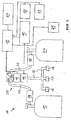
- FIG. 1 is a basic structure of a liquid gas system with an embodiment of a termeabsperr worn 27 of the invention illustrated.
- the liquefied gas plant 11 initially comprises two gas reservoirs 19, 20, which are connected via leads 30 to a switch 29, in which a pressure regulator 24 is integrated at the same time.
- a pressure regulator 24 In the supply lines 30 can still be arranged a hose rupture 28 each.
- the switch 29 operates as follows: When two full gas reservoirs 19, 20 are connected, the switch 29 is adjusted to remove the gas from the preselected gas reservoir. When this gas storage tank becomes empty, this switch 29 automatically switches to the second full gas storage tank.
- the switch 29 switches in the present embodiment automatically from the empty reservoir to the full (and can also be controlled via an electronic unit to be mentioned 13), so that either either the gas reservoir 19 or the gas reservoir 20 gas can be removed. In most applications, it may be useful to first empty a first gas storage tank and then switch to the second gas storage tank.
- Which gas storage container is currently selected can also be output via an information output unit 21, for example a screen.
- an electromagnetic gas valve 12 and, subsequently, a flow sensor 14 are provided.
- the electromagnetic gas valve is designed to interrupt a gas flow to the gas consumers 16 to 18, wherein this preferably takes place in that a power supply of the electromagnetic Gas valve 12 is interrupted.
- the electromagnetic gas valve 12 remains in the open position as long as a predetermined electrical potential is applied to it. If this electrical potential drops or if this potential is 0, the electromagnetic gas valve closes and interrupts the gas supply to the majority of the gas consumers 16 to 18.
- the flow sensor 14 is able to detect a current feed flow F a to the gas consumers 16 to 18.
- the current load flow F a is in this case transmitted to an evaluation unit 15.
- the evaluation unit 15 compares the current feed flow F a in this embodiment both with a permissible maximum gas flow F max , which is calculated from the sum of all consumption values F s of the gas consumers 16 to 18 of the liquefied gas plant, and with a previous gas flow F v .
- the current read flow F a read in each case is stored in the evaluation unit so that it is available as the previous flow of flows F v in the next polling cycle.
- the current flow of gases F a is therefore subjected simultaneously to two plausibility tests, namely on the one hand to determine whether it is above the total permissible maximum flow rate F max and then to determine whether a maximum permissible change rate ⁇ max has been exceeded in comparison with a previous flow of flows F v is. If one of the two cases, that is, the evaluation determines a current under the criteria of the LPG system 11 seems plausible current flow F a , a closing or error signal is transmitted to an electronic unit 13, the electromagnetic gas valve 12 in the closed position brings. Specifically, in the present case, the electronic unit 13 would interrupt the power supply to the electromagnetic gas valve 12 so that it closes automatically.
- the electronic unit 12 or the evaluation unit 15 are also preferably in operative connection with the information output unit 21 in such a way that the data determined by the evaluation unit 15 can be output if necessary and the current states of the liquefied gas system are displayed, for example the current gas flow F a , a previous gas flow rate F v , the specified system parameters ⁇ max and F max , the consumption value of the largest gas consumer F G , the sum of all consumption values of the gas consumers of the liquefied gas system F s , a gas consumption since the last bottle change, a residual amount of gas in each current gas storage tank and other information or any sub-combinations thereof.
- the safety shut-off device 27 shown here by way of example only has two accident sensors, namely an acceleration sensor 22 and an inclination sensor 23, so that when at least one of the two sensors responds to an accident, it also includes two accident sensors and this information in the electronics unit 13 also causes the electromagnetic gas valve 12 to close by interrupting the power supply.
- a manual switch 25 for example, be provided in the interior of a vehicle or vehicle trailer, which also causes a closing of the electromagnetic gas valve, for example, by the fact that the electronic unit 13 interrupts the power supply to the electromagnetic gas valve 12.
- the already mentioned switch 29 may also be connected to the electronic unit 13, so that the electronic unit 13 receives a signal from the switch 29 that has been switched over and a corresponding display or evaluation can take place.
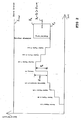
- FIG. 2 is still purely for illustrative purposes, a possible gas consumption over time shown, with the last event, an increase of the current gas flow F a over a previous gas flow F v is carried out, which is above a maximum allowable rate of change ⁇ max , so that in this way on the evaluation unit 15th and the electronic unit 13, a shutoff of the electromagnetic gas valve 12 is effected.
- the procedureabsperr worn 27 thus shuts off the gas supply, if F a - F v > ⁇ Max first alternative of an implausible gas consumption or F a > F Max second alternative of implausible gas consumption ,
- both plausibility checks are performed and a shutdown is already effected if only a plausibility check results in an implausible gas consumption.
Landscapes
- Engineering & Computer Science (AREA)
- General Engineering & Computer Science (AREA)
- Mechanical Engineering (AREA)
- Filling Or Discharging Of Gas Storage Vessels (AREA)
- Measuring Volume Flow (AREA)
- Examining Or Testing Airtightness (AREA)
Claims (27)
- Dispositif d'arrêt de sécurité (27) pour une installation de gaz liquide (11) à un ou plusieurs consommateurs de gaz (16 à 18) pour véhicules et/ou remorques de véhicule destiné à éviter un dégagement intempestif de gaz comprenanta) une vanne de gaz électromagnétique (12) destinée à arrêter l'arrivée de gaz,b) une unité électronique (13) destinée à activer la vanne de gaz électromagnétique (12), un capteur de débit (14) destiné à déterminer un flux de gaz actuel Fa qui s'écoule d'un réservoir de stockage de gaz (19, 20), caractérisé parc) une unité d'évaluation (15) destinée à comparer le flux de gaz actuel Fa à un flux de gaz précédent Fv etd) une unité électronique (13) qui active la vanne de gaz électromagnétique (12) pour l'arrêt de l'arrivée de gaz si l'unité d'évaluation (15) a déterminé un flux de gaz actuel Fa qui diffère du flux de gaz précédent Fv de plus d'un taux de changement maximal admissible Δmax.
- Dispositif d'arrêt de sécurité (27) pour une installation de gaz liquide (11) à un ou plusieurs consommateurs de gaz (16 à 18) pour véhicules et/ou remorques de véhicule destiné à éviter un dégagement intempestif de gaz selon la revendication 1, comprenanta) une vanne de gaz électromagnétique (12) destinée à arrêter l'arrivée de gaz,b) une unité électronique (13) destinée à activer la vanne de gaz électromagnétique (12), un capteur de débit (14) destiné à déterminer un flux de gaz actuel Fa qui s'écoule d'un réservoir de stockage de gaz (19, 20),c) une unité d'évaluation (15) destinée à comparer le flux de gaz actuel à un flux de gaz maximal admissible Fmax,d) une unité électronique (13) qui active la vanne de gaz électromagnétique (12) pour l'arrêt de l'arrivée de gaz si l'unité d'évaluation (15) a déterminé un flux de gaz actuel Fa qui est supérieur au flux de gaz maximal admissible Fmax.
- Dispositif d'arrêt de sécurité selon la revendication 1,
caractérisé en ce que
le taux de changement maximal admissible Δmax est calculé en fonction de la valeur de consommation de la plus grande consommation de gaz de l'installation de gaz liquide (11). - Dispositif d'arrêt de sécurité selon la revendication 3,
caractérisé en ce que
le taux de changement maximal admissible Δmax est supérieur à la valeur de consommation de la plus grande consommation de gaz FG d'une valeur de tolérance de moins de 30 %, de préférence de moins de 20 %. - Dispositif d'arrêt de sécurité selon l'une des revendications 2 à 4, caractérisé en ce que
le flux de gaz maximal admissible Fmax est calculé en fonction de la somme de toutes les valeurs de consommation FS des consommateurs de gaz (16 à 18) de l'installation de gaz liquide (11). - Dispositif d'arrêt de sécurité selon la revendication 5,
caractérisé en ce que
le flux de gaz maximal admissible Fmax est supérieur à la somme de toutes les valeurs de consommation FS des consommateurs de gaz (16 à 18) de l'installation de gaz liquide (11) d'une valeur de tolérance de moins de 25 %, de préférence de moins de 15 %. - Dispositif d'arrêt de sécurité selon l'une des revendications 1 à 6, caractérisé en ce que
le taux de changement maximal admissible Δmax et/ou le flux de gaz maximal admissible Fmax sont définis de manière respectivement actuelle sur la base d'informations de consommation actuelles des consommateurs de gaz (16 à 18). - Dispositif d'arrêt de sécurité selon la revendication 7,
caractérisé en ce que
les consommateurs de gaz (16 à 18) transmettent des informations indiquant s'ils sont en marche ou à l'arrêt, et/ou sur la consommation de gaz escomptée à l'unité électronique (13) et/ou à l'unité d'évaluation (15), par exemple via un système de bus. - Dispositif d'arrêt de sécurité selon l'une des revendications 1 à 8,
caractérisé en ce que
l'unité d'évaluation (15) est en liaison active avec une unité de sortie d'informations (21) pour sortir une ou plusieurs des informations suivantes :- flux de gaz actuel- flux de gaz intégré sur une période de temps, en particulier flux de gaz intégré depuis un changement de bouteille- quantité résiduelle actuellement disponible dans une bouteille de gaz ou un réservoir de stockage de gaz- avertissement en cas de dépassement vers le bas d'une quantité résiduelle prédéterminée. - Dispositif d'arrêt de sécurité selon l'une des revendications 1 à 9,
caractérisé en ce que
un capteur d'accident (22, 23) destiné à déterminer un accident du véhicule et/ou de la remorque de véhicule est en outre prévu, qui se trouve en liaison active avec l'unité d'évaluation (15) et/ou l'unité électronique (13), sachant que l'unité électronique (13) active la vanne de gaz électromagnétique (12) destinée à arrêter l'arrivée de gaz en cas de signalisation d'accident provenant du capteur d'accident (22, 23). - Dispositif d'arrêt de sécurité selon l'une des revendications 1 à 10,
caractérisé en ce que
la vanne de gaz électromagnétique (12) arrête l'arrivée de gaz dans l'installation de gaz liquide (11) en l'absence d'alimentation en énergie électrique. - Dispositif d'arrêt de sécurité selon l'une des revendications 1 à 11,
caractérisé en ce que
la vanne de gaz électromagnétique (12) est située en aval d'un régulateur de pression (24) en termes d'écoulement de gaz. - Dispositif d'arrêt de sécurité selon la revendication 12,
caractérisé en ce que
la vanne de gaz électromagnétique (12) est placée directement au niveau du régulateur de pression (24). - Dispositif d'arrêt de sécurité selon la revendication 12 ou 13,
caractérisé en ce que
le régulateur de pression (24) est placé ou apte à être placé directement sur un réservoir de stockage de gaz (19, 20). - Dispositif d'arrêt de sécurité selon l'une des revendications 1 à 11,
caractérisé en ce que
la vanne de gaz électromagnétique (12) est située en amont d'un régulateur de pression (24) en termes d'écoulement de gaz. - Dispositif d'arrêt de sécurité selon la revendication 15,
caractérisé en ce que
la vanne de gaz électromagnétique (12) est placée ou apte à être placée directement sur un réservoir de stockage de gaz (19, 20). - Dispositif d'arrêt de sécurité selon la revendication 15 ou 16,
caractérisé en ce que
la vanne de gaz électromagnétique (12) est placée directement sur le régulateur de pression (24). - Dispositif d'arrêt de sécurité selon l'une des revendications précédentes,
caractérisé en ce que
la vanne de gaz électromagnétique (12) est raccordée ou apte à être raccordée à une batterie logée dans le véhicule et/ou la remorque de véhicule. - Dispositif d'arrêt de sécurité selon l'une des revendications précédentes,
caractérisé en ce que
le capteur d'accident est un capteur d'accélération (22) et/ou un capteur d'inclinaison (23). - Dispositif d'arrêt de sécurité selon l'une des revendications précédentes,
caractérisé en ce que
un commutateur (25) disposé de préférence à l'intérieur du véhicule ou de la remorque de véhicule est prévu pour la coupure manuelle de l'alimentation en gaz. - Dispositif d'arrêt de sécurité selon l'une des revendications précédentes,
caractérisé en ce que
un ou plusieurs capteurs supplémentaires sont prévus en plus, en particulier des capteurs de gaz et/ou des détecteurs de fumée qui déterminent des situations de danger supplémentaires, en particulier un échappement de gaz et/ou un incendie dans le véhicule et/ou la remorque de véhicule, sachant que les capteurs sont reliés à l'unité électronique (13) pour la transmission d'une signalisation de danger. - Dispositif d'arrêt de sécurité selon l'une des revendications précédentes,
caractérisé en ce que
l'unité électronique (13) et/ou les capteurs (22, 23) sont conçus de telle sorte que la vanne de gaz électromagnétique (12) arrête automatiquement l'arrivée de gaz en cas de défaut. - Installation de gaz liquide (11) pour véhicules et/ou remorques de véhicule avec un dispositif d'arrêt de sécurité selon l'une des revendications 1 à 22,a) dans laquelle un ou plusieurs réservoirs de stockage de gaz (19, 20) sont reliés ou aptes à être reliés à un ou plusieurs consommateurs de gaz (16 à 18) via une ou plusieurs conduites de gaz (26),b) avec un dispositif d'arrêt de sécurité (27) destiné à éviter un dégagement intempestif de gaz.
- Procédé pour l'arrêt de sécurité d'une installation de gaz liquide (11) pour véhicules et/ou remorques de véhicule, en particulier d'une installation de gaz liquide (11) selon la revendication 23, destiné à éviter un dégagement intempestif de gaz, de préférence en utilisant un dispositif d'arrêt de sécurité (27) selon l'une des revendications 1 à 22, dans lequela) un flux de gaz actuel Fa qui s'écoule d'une source de gaz (19, 20) est déterminé,b) le flux de gaz actuel Fa est comparé au flux de gaz précédent Fv etc) si le flux de gaz actuel Fa diffère du flux de gaz précédent Fv de plus d'un taux de changement maximal admissible Δmax, l'arrivée de gaz est interrompue via une vanne de gaz activée électromagnétiquement (12).
- Procédé selon la revendication 24, pour l'arrêt de sécurité d'une installation de gaz liquide (11) pour véhicules et/ou remorques de véhicule, en particulier d'une installation de gaz liquide (11) selon la revendication 23, destiné à éviter un dégagement intempestif de gaz en cas d'accident du véhicule et/ou de la remorque de véhicule, de préférence en utilisant un dispositif d'arrêt de sécurité (27) selon l'une des revendications 1 à 22, dans lequela) un flux de gaz actuel Fa qui s'écoule d'une source de gaz (19, 20) est déterminé,b) le flux de gaz actuel Fa est comparé à un flux de gaz maximal admissible Fmax etc) si le flux de gaz actuel est supérieur au flux de gaz maximal admissible Fmax, l'arrivée de gaz est interrompue via une vanne de gaz activée électromagnétiquement (12).
- Procédé selon la revendication 24 ou 25,
caractérisé en ce que
pour l'arrêt de l'arrivée de gaz dans l'installation de gaz liquide, l'arrivée de courant à la vanne de gaz électromagnétique est interrompue. - Procédé selon l'une des revendications 24 à 26,
caractérisé en ce que
le taux de changement maximal admissible Δmax et/ou le flux de gaz maximal admissible Fmax sont présélectionnés de manière fixe pour une configuration respectivement donnée de l'installation de gaz liquide (11) ou sont adaptés à des situations de consommation actuelles ou des situations de consommation escomptées au cours du fonctionnement de l'installation de gaz liquide (11).
Priority Applications (2)
| Application Number | Priority Date | Filing Date | Title |
|---|---|---|---|
| DK15194927.8T DK3006812T3 (da) | 2007-08-01 | 2008-08-01 | Elektronisk flowsensor |
| EP15194927.8A EP3006812B1 (fr) | 2007-08-01 | 2008-08-01 | Capteur de débit électronique |
Applications Claiming Priority (1)
| Application Number | Priority Date | Filing Date | Title |
|---|---|---|---|
| DE200710035977 DE102007035977B4 (de) | 2007-08-01 | 2007-08-01 | Elektronischer Durchflusssensor |
Related Child Applications (2)
| Application Number | Title | Priority Date | Filing Date |
|---|---|---|---|
| EP15194927.8A Division EP3006812B1 (fr) | 2007-08-01 | 2008-08-01 | Capteur de débit électronique |
| EP15194927.8A Division-Into EP3006812B1 (fr) | 2007-08-01 | 2008-08-01 | Capteur de débit électronique |
Publications (2)
| Publication Number | Publication Date |
|---|---|
| EP2020560A1 EP2020560A1 (fr) | 2009-02-04 |
| EP2020560B1 true EP2020560B1 (fr) | 2016-10-12 |
Family
ID=39790220
Family Applications (2)
| Application Number | Title | Priority Date | Filing Date |
|---|---|---|---|
| EP15194927.8A Active EP3006812B1 (fr) | 2007-08-01 | 2008-08-01 | Capteur de débit électronique |
| EP08161617.9A Active EP2020560B1 (fr) | 2007-08-01 | 2008-08-01 | Capteur de débit électronique |
Family Applications Before (1)
| Application Number | Title | Priority Date | Filing Date |
|---|---|---|---|
| EP15194927.8A Active EP3006812B1 (fr) | 2007-08-01 | 2008-08-01 | Capteur de débit électronique |
Country Status (8)
| Country | Link |
|---|---|
| US (2) | US8720469B2 (fr) |
| EP (2) | EP3006812B1 (fr) |
| AU (1) | AU2008282030B2 (fr) |
| DE (1) | DE102007035977B4 (fr) |
| DK (2) | DK2020560T3 (fr) |
| ES (2) | ES2609926T3 (fr) |
| PT (2) | PT3006812T (fr) |
| WO (1) | WO2009015895A1 (fr) |
Families Citing this family (13)
| Publication number | Priority date | Publication date | Assignee | Title |
|---|---|---|---|---|
| DE102007035977B4 (de) | 2007-08-01 | 2009-07-16 | Toptron Gmbh | Elektronischer Durchflusssensor |
| NO2948624T3 (fr) * | 2013-03-15 | 2018-03-31 | ||
| US20150286222A1 (en) * | 2014-04-05 | 2015-10-08 | Kevin William Goldstein | Automatic Fluid Flow Control System |
| EP3056794A1 (fr) * | 2015-02-16 | 2016-08-17 | Salzburger Aluminium Aktiengesellschaft | Dispositif de réception d'un fluide cryogénique |
| SE540106C2 (en) | 2016-04-27 | 2018-03-27 | Scania Cv Ab | A connection arrangement for a liquefied gas fuel system for a vehicle |
| DE102016112888A1 (de) | 2016-07-13 | 2018-01-18 | Truma Gerätetechnik GmbH & Co. KG | Flüssiggasanlage |
| US10726640B2 (en) * | 2016-11-15 | 2020-07-28 | At&T Mobility Ii Llc | Facilitation of smart communications hub to support driverless vehicles in 5G networks or other next generation networks |
| WO2018107217A1 (fr) * | 2016-12-14 | 2018-06-21 | Anthony Joseph Tambasco | Système et procédé de surveillance à distance de l'état d'un contenant de gaz |
| CN112236661A (zh) * | 2018-06-07 | 2021-01-15 | 传感器公司 | 颗粒浓度分析系统和方法 |
| EP3833572B1 (fr) * | 2018-08-10 | 2023-03-29 | Carrier Corporation | Crash detection system for transport refrigeration units |
| DE102018007980A1 (de) * | 2018-10-10 | 2020-04-16 | Truma Gerätetechnik GmbH & Co. KG | Verfahren sowie Vorrichtung zum Steuern von Gasverbrauchern |
| JP6600430B1 (ja) * | 2019-02-01 | 2019-10-30 | 岩谷産業株式会社 | 水素ガスディスペンサーの検査装置 |
| CN112969171B (zh) * | 2021-02-26 | 2023-02-28 | 徐逸轩 | 浮空通讯装置,其组网通讯和数据传输方法 |
Family Cites Families (30)
| Publication number | Priority date | Publication date | Assignee | Title |
|---|---|---|---|---|
| US4223692A (en) * | 1977-10-19 | 1980-09-23 | Perry Landis H | Recreational vehicle safety system |
| JPS59187178A (ja) * | 1983-04-08 | 1984-10-24 | Chuo Sansho Kk | ガス安全装置 |
| DE3619877A1 (de) * | 1985-06-17 | 1987-01-22 | Tokyo Gas Co Ltd | Vorrichtung zum verhindern von gasunfaellen |
| DE68915011T2 (de) * | 1988-02-10 | 1994-08-25 | Matsushita Electric Ind Co Ltd | Gasabschaltvorrichtung. |
| US5632269A (en) * | 1989-09-22 | 1997-05-27 | Respironics Inc. | Breathing gas delivery method and apparatus |
| US5360139A (en) * | 1993-01-22 | 1994-11-01 | Hydra Rig, Inc. | Liquified natural gas fueling facility |
| EP0653585B1 (fr) | 1993-11-08 | 1997-10-29 | Maschinenfabrik Sulzer-Burckhardt AG | Procédé et installation pour la remplissage rapide d'un réservoir sous pression avec un fluide gazeux |
| US5673735A (en) * | 1995-02-07 | 1997-10-07 | Aurora Technology Corporation | Process for storing and delivering gas |
| CN1111830C (zh) * | 1995-05-19 | 2003-06-18 | 松下电器产业株式会社 | 煤气安全管理系统 |
| DE19522358C1 (de) * | 1995-06-20 | 1997-01-09 | Siemens Ag | Vorrichtung und Verfahren zur Leckageüberwachung bei der Befüllung einer elektrischen Maschine mit einem Füllgas |
| DE19643801B4 (de) | 1996-10-30 | 2005-08-25 | Gall, Sieghard, Dr. | Verfahren und Vorrichtung zum Gas-Befüllen eines Behälters auf einem gewünschten Befülldruck und/oder eine gewünschte Befüllmenge |
| US5694960A (en) * | 1996-11-05 | 1997-12-09 | Turk; Edward J. | Hazardous gas protection system and method for automatic valve closure |
| US7458387B2 (en) * | 1997-02-21 | 2008-12-02 | Mcgill James C | Emergency gas and electricity shutoff apparatus and control system |
| US5960807A (en) * | 1998-05-05 | 1999-10-05 | Reyman; Mark | Vibration and flow actuated valve shutoff system |
| US6343617B1 (en) | 1999-07-09 | 2002-02-05 | Millipore Corporation | System and method of operation of a digital mass flow controller |
| EP1205704B1 (fr) | 2000-11-08 | 2008-03-26 | GreenField AG | Procédé de remplissage d'un réservoir avec du gaz |
| EP1356973A1 (fr) * | 2002-04-26 | 2003-10-29 | Lambros Pamboris | Dispositif anti feu pour un moteur d'automobile |
| DE10237834A1 (de) * | 2002-08-19 | 2004-03-04 | Robert Bosch Gmbh | Sicherheitssystem für eine Einrichtung zur Energieerzeugung |
| DE10244139A1 (de) * | 2002-09-23 | 2004-04-01 | Bayerische Motoren Werke Ag | Sicherheitssystem für den Betrieb wasserstoffumsetzender Vorrichtungen in geschlossenen oder teilgeschlossenen Räumen oder Behältern |
| EP1450097A3 (fr) | 2003-02-19 | 2007-12-12 | Taiyo Nippon Sanso Corporation | Dispositif d'alimentation en carburant et procédé de détection de fuites |
| JP4552399B2 (ja) * | 2003-08-07 | 2010-09-29 | トヨタ自動車株式会社 | 複数タンクからなるタンクシステムおよびその制御方法 |
| JP4707427B2 (ja) * | 2005-03-23 | 2011-06-22 | トキコテクノ株式会社 | ガス供給装置 |
| JP2006283840A (ja) * | 2005-03-31 | 2006-10-19 | Hitachi Ltd | ガス供給装置 |
| TWI386629B (zh) * | 2005-05-09 | 2013-02-21 | Panasonic Corp | Flow measurement device |
| DE102005040024B4 (de) * | 2005-08-23 | 2007-10-31 | Cavagna Group S.P.A. | Vorrichtung und Verfahren zur Sicherheitsabsperrung einer Flüssiggas-Anlage für Fahrzeuge und/oder Fahrzeuganhänger im Falle eines Unfalls |
| US7562668B2 (en) * | 2006-04-26 | 2009-07-21 | Umac Incorporated | Excess flow valves |
| US20080185050A1 (en) * | 2007-02-05 | 2008-08-07 | Timothy David Mulligan | Fluid supply monitoring system |
| JP4544277B2 (ja) * | 2007-07-12 | 2010-09-15 | パナソニック株式会社 | ガス遮断装置 |
| DE102007035977B4 (de) | 2007-08-01 | 2009-07-16 | Toptron Gmbh | Elektronischer Durchflusssensor |
| JP5540500B2 (ja) * | 2008-12-19 | 2014-07-02 | パナソニック株式会社 | ガス遮断装置 |
-
2007
- 2007-08-01 DE DE200710035977 patent/DE102007035977B4/de active Active
-
2008
- 2008-07-31 US US12/671,638 patent/US8720469B2/en active Active
- 2008-07-31 AU AU2008282030A patent/AU2008282030B2/en active Active
- 2008-07-31 WO PCT/EP2008/006331 patent/WO2009015895A1/fr active Application Filing
- 2008-08-01 PT PT151949278T patent/PT3006812T/pt unknown
- 2008-08-01 ES ES08161617.9T patent/ES2609926T3/es active Active
- 2008-08-01 DK DK08161617.9T patent/DK2020560T3/en active
- 2008-08-01 EP EP15194927.8A patent/EP3006812B1/fr active Active
- 2008-08-01 DK DK15194927.8T patent/DK3006812T3/da active
- 2008-08-01 PT PT81616179T patent/PT2020560T/pt unknown
- 2008-08-01 ES ES15194927T patent/ES2788861T3/es active Active
- 2008-08-01 EP EP08161617.9A patent/EP2020560B1/fr active Active
-
2014
- 2014-02-07 US US14/175,390 patent/US9587754B2/en active Active
Also Published As
| Publication number | Publication date |
|---|---|
| PT2020560T (pt) | 2017-01-19 |
| DE102007035977B4 (de) | 2009-07-16 |
| EP3006812B1 (fr) | 2020-02-19 |
| DK3006812T3 (da) | 2020-05-04 |
| EP3006812A1 (fr) | 2016-04-13 |
| US20110259426A1 (en) | 2011-10-27 |
| AU2008282030B2 (en) | 2015-02-05 |
| US9587754B2 (en) | 2017-03-07 |
| US8720469B2 (en) | 2014-05-13 |
| PT3006812T (pt) | 2020-05-07 |
| DE102007035977A1 (de) | 2009-02-19 |
| EP2020560A1 (fr) | 2009-02-04 |
| DK2020560T3 (en) | 2017-01-30 |
| AU2008282030A1 (en) | 2009-02-05 |
| ES2788861T3 (es) | 2020-10-23 |
| US20140150884A1 (en) | 2014-06-05 |
| ES2609926T3 (es) | 2017-04-25 |
| WO2009015895A1 (fr) | 2009-02-05 |
Similar Documents
| Publication | Publication Date | Title |
|---|---|---|
| EP2020560B1 (fr) | Capteur de débit électronique | |
| EP3270034B1 (fr) | Installation de gaz liquide | |
| DE60208563T2 (de) | Überwachungssystem für einen Druckbehälter | |
| EP3479007A1 (fr) | Soupape de réservoir | |
| EP2656087B1 (fr) | Essai d'un dispositif de contrôle destiné à déterminer un état de tension d'un réseau de bord à haute tension | |
| DE102009049687A1 (de) | Gasbehälteranordnung und Verfahren zum Betreiben einer Gasbehälteranordnung | |
| DE3730103A1 (de) | Laststeuersystem und verfahren zum trennen eines unter-busses von einem haupt-bus | |
| WO2021018457A1 (fr) | Système de réservoir | |
| EP2532550A2 (fr) | Dispositif de surveillance de réservoir contre le vol de carburant depuis un réservoir de carburant | |
| EP1760390B1 (fr) | Dispositif et procédé pour fermer un système de gaz liquéfié d'un véhicule en cas d'accident | |
| EP3489062B1 (fr) | Système de réservoir pour un véhicule | |
| EP2840294A1 (fr) | Système de distribution de lubrifiant central d'une machine de thermoformage | |
| DE4413302A1 (de) | Vorrichtung zum Abfüllen von Benzin | |
| EP3431149B1 (fr) | Procédé et dispositif de surveillance à distance d'extincteurs ou d'installations d'extinction d'incendie | |
| EP2226515B1 (fr) | Capteur de signal limite et procédé d'emploi d'un capteur de signal limite | |
| WO2006034852A1 (fr) | Procede et dispositif servant au diagnostic d'appareils techniques agences a l'interieur d'une installation industrielle | |
| EP3489061A1 (fr) | Système de réservoir pour un véhicule | |
| EP1690148B1 (fr) | Procede de surveillance, de saisie et de transmission de donnees d'un processus | |
| DE102015013061A1 (de) | Verfahren zum Detektieren einer Verschmutzung | |
| DE102008028980A1 (de) | System sowie Verfahren zur Diagnose des technischen Betriebszustandes eines Leistungsschalters | |
| EP3377869A1 (fr) | Système d'encapsulage à surpression pour la protection anti-explosion et procédé de fonctionnement correspondant | |
| DE102011010507B4 (de) | Verfahren zum Überwachen eines Tanks für ein Reduktionsmittel in einem Kraftfahrzeug | |
| DE102017208089A1 (de) | Dichtigkeitskontrolle in einer Medienversorgungsanlage | |
| EP0999301A2 (fr) | Dispositif limiteur de débit | |
| DE102013014280A1 (de) | Kraftstoffspeichersystem |
Legal Events
| Date | Code | Title | Description |
|---|---|---|---|
| PUAI | Public reference made under article 153(3) epc to a published international application that has entered the european phase |
Free format text: ORIGINAL CODE: 0009012 |
|
| AK | Designated contracting states |
Kind code of ref document: A1 Designated state(s): AT BE BG CH CY CZ DE DK EE ES FI FR GB GR HR HU IE IS IT LI LT LU LV MC MT NL NO PL PT RO SE SI SK TR |
|
| AX | Request for extension of the european patent |
Extension state: AL BA MK RS |
|
| RAP1 | Party data changed (applicant data changed or rights of an application transferred) |
Owner name: TOPTRON GMBH Owner name: CAVAGNA GROUP S.P.A. |
|
| 17P | Request for examination filed |
Effective date: 20090804 |
|
| AKX | Designation fees paid |
Designated state(s): AT BE BG CH CY CZ DE DK EE ES FI FR GB GR HR HU IE IS IT LI LT LU LV MC MT NL NO PL PT RO SE SI SK TR |
|
| 17Q | First examination report despatched |
Effective date: 20091119 |
|
| RIN1 | Information on inventor provided before grant (corrected) |
Inventor name: CRAMER, WILHELM |
|
| GRAP | Despatch of communication of intention to grant a patent |
Free format text: ORIGINAL CODE: EPIDOSNIGR1 |
|
| INTG | Intention to grant announced |
Effective date: 20160414 |
|
| GRAS | Grant fee paid |
Free format text: ORIGINAL CODE: EPIDOSNIGR3 |
|
| GRAA | (expected) grant |
Free format text: ORIGINAL CODE: 0009210 |
|
| AK | Designated contracting states |
Kind code of ref document: B1 Designated state(s): AT BE BG CH CY CZ DE DK EE ES FI FR GB GR HR HU IE IS IT LI LT LU LV MC MT NL NO PL PT RO SE SI SK TR |
|
| REG | Reference to a national code |
Ref country code: GB Ref legal event code: FG4D Free format text: NOT ENGLISH |
|
| REG | Reference to a national code |
Ref country code: CH Ref legal event code: EP |
|
| REG | Reference to a national code |
Ref country code: AT Ref legal event code: REF Ref document number: 836847 Country of ref document: AT Kind code of ref document: T Effective date: 20161015 |
|
| REG | Reference to a national code |
Ref country code: IE Ref legal event code: FG4D Free format text: LANGUAGE OF EP DOCUMENT: GERMAN |
|
| REG | Reference to a national code |
Ref country code: DE Ref legal event code: R096 Ref document number: 502008014702 Country of ref document: DE |
|
| REG | Reference to a national code |
Ref country code: PT Ref legal event code: SC4A Ref document number: 2020560 Country of ref document: PT Date of ref document: 20170119 Kind code of ref document: T Free format text: AVAILABILITY OF NATIONAL TRANSLATION Effective date: 20170111 |
|
| REG | Reference to a national code |
Ref country code: DK Ref legal event code: T3 Effective date: 20170126 |
|
| REG | Reference to a national code |
Ref country code: LT Ref legal event code: MG4D |
|
| REG | Reference to a national code |
Ref country code: NL Ref legal event code: MP Effective date: 20161012 |
|
| PG25 | Lapsed in a contracting state [announced via postgrant information from national office to epo] |
Ref country code: LV Free format text: LAPSE BECAUSE OF FAILURE TO SUBMIT A TRANSLATION OF THE DESCRIPTION OR TO PAY THE FEE WITHIN THE PRESCRIBED TIME-LIMIT Effective date: 20161012 |
|
| REG | Reference to a national code |
Ref country code: ES Ref legal event code: FG2A Ref document number: 2609926 Country of ref document: ES Kind code of ref document: T3 Effective date: 20170425 |
|
| PG25 | Lapsed in a contracting state [announced via postgrant information from national office to epo] |
Ref country code: NO Free format text: LAPSE BECAUSE OF FAILURE TO SUBMIT A TRANSLATION OF THE DESCRIPTION OR TO PAY THE FEE WITHIN THE PRESCRIBED TIME-LIMIT Effective date: 20170112 Ref country code: SE Free format text: LAPSE BECAUSE OF FAILURE TO SUBMIT A TRANSLATION OF THE DESCRIPTION OR TO PAY THE FEE WITHIN THE PRESCRIBED TIME-LIMIT Effective date: 20161012 Ref country code: GR Free format text: LAPSE BECAUSE OF FAILURE TO SUBMIT A TRANSLATION OF THE DESCRIPTION OR TO PAY THE FEE WITHIN THE PRESCRIBED TIME-LIMIT Effective date: 20170113 Ref country code: LT Free format text: LAPSE BECAUSE OF FAILURE TO SUBMIT A TRANSLATION OF THE DESCRIPTION OR TO PAY THE FEE WITHIN THE PRESCRIBED TIME-LIMIT Effective date: 20161012 |
|
| PG25 | Lapsed in a contracting state [announced via postgrant information from national office to epo] |
Ref country code: IS Free format text: LAPSE BECAUSE OF FAILURE TO SUBMIT A TRANSLATION OF THE DESCRIPTION OR TO PAY THE FEE WITHIN THE PRESCRIBED TIME-LIMIT Effective date: 20170212 Ref country code: NL Free format text: LAPSE BECAUSE OF FAILURE TO SUBMIT A TRANSLATION OF THE DESCRIPTION OR TO PAY THE FEE WITHIN THE PRESCRIBED TIME-LIMIT Effective date: 20161012 Ref country code: PL Free format text: LAPSE BECAUSE OF FAILURE TO SUBMIT A TRANSLATION OF THE DESCRIPTION OR TO PAY THE FEE WITHIN THE PRESCRIBED TIME-LIMIT Effective date: 20161012 Ref country code: HR Free format text: LAPSE BECAUSE OF FAILURE TO SUBMIT A TRANSLATION OF THE DESCRIPTION OR TO PAY THE FEE WITHIN THE PRESCRIBED TIME-LIMIT Effective date: 20161012 Ref country code: FI Free format text: LAPSE BECAUSE OF FAILURE TO SUBMIT A TRANSLATION OF THE DESCRIPTION OR TO PAY THE FEE WITHIN THE PRESCRIBED TIME-LIMIT Effective date: 20161012 |
|
| REG | Reference to a national code |
Ref country code: DE Ref legal event code: R097 Ref document number: 502008014702 Country of ref document: DE |
|
| PG25 | Lapsed in a contracting state [announced via postgrant information from national office to epo] |
Ref country code: RO Free format text: LAPSE BECAUSE OF FAILURE TO SUBMIT A TRANSLATION OF THE DESCRIPTION OR TO PAY THE FEE WITHIN THE PRESCRIBED TIME-LIMIT Effective date: 20161012 Ref country code: CZ Free format text: LAPSE BECAUSE OF FAILURE TO SUBMIT A TRANSLATION OF THE DESCRIPTION OR TO PAY THE FEE WITHIN THE PRESCRIBED TIME-LIMIT Effective date: 20161012 Ref country code: SK Free format text: LAPSE BECAUSE OF FAILURE TO SUBMIT A TRANSLATION OF THE DESCRIPTION OR TO PAY THE FEE WITHIN THE PRESCRIBED TIME-LIMIT Effective date: 20161012 Ref country code: EE Free format text: LAPSE BECAUSE OF FAILURE TO SUBMIT A TRANSLATION OF THE DESCRIPTION OR TO PAY THE FEE WITHIN THE PRESCRIBED TIME-LIMIT Effective date: 20161012 |
|
| PLBE | No opposition filed within time limit |
Free format text: ORIGINAL CODE: 0009261 |
|
| STAA | Information on the status of an ep patent application or granted ep patent |
Free format text: STATUS: NO OPPOSITION FILED WITHIN TIME LIMIT |
|
| REG | Reference to a national code |
Ref country code: FR Ref legal event code: PLFP Year of fee payment: 10 |
|
| PG25 | Lapsed in a contracting state [announced via postgrant information from national office to epo] |
Ref country code: BG Free format text: LAPSE BECAUSE OF FAILURE TO SUBMIT A TRANSLATION OF THE DESCRIPTION OR TO PAY THE FEE WITHIN THE PRESCRIBED TIME-LIMIT Effective date: 20170112 |
|
| 26N | No opposition filed |
Effective date: 20170713 |
|
| PG25 | Lapsed in a contracting state [announced via postgrant information from national office to epo] |
Ref country code: SI Free format text: LAPSE BECAUSE OF FAILURE TO SUBMIT A TRANSLATION OF THE DESCRIPTION OR TO PAY THE FEE WITHIN THE PRESCRIBED TIME-LIMIT Effective date: 20161012 |
|
| REG | Reference to a national code |
Ref country code: CH Ref legal event code: PL |
|
| PG25 | Lapsed in a contracting state [announced via postgrant information from national office to epo] |
Ref country code: MC Free format text: LAPSE BECAUSE OF FAILURE TO SUBMIT A TRANSLATION OF THE DESCRIPTION OR TO PAY THE FEE WITHIN THE PRESCRIBED TIME-LIMIT Effective date: 20161012 |
|
| PG25 | Lapsed in a contracting state [announced via postgrant information from national office to epo] |
Ref country code: LI Free format text: LAPSE BECAUSE OF NON-PAYMENT OF DUE FEES Effective date: 20170831 Ref country code: CH Free format text: LAPSE BECAUSE OF NON-PAYMENT OF DUE FEES Effective date: 20170831 |
|
| REG | Reference to a national code |
Ref country code: IE Ref legal event code: MM4A |
|
| REG | Reference to a national code |
Ref country code: BE Ref legal event code: MM Effective date: 20170831 |
|
| PG25 | Lapsed in a contracting state [announced via postgrant information from national office to epo] |
Ref country code: LU Free format text: LAPSE BECAUSE OF NON-PAYMENT OF DUE FEES Effective date: 20170801 |
|
| PG25 | Lapsed in a contracting state [announced via postgrant information from national office to epo] |
Ref country code: IE Free format text: LAPSE BECAUSE OF NON-PAYMENT OF DUE FEES Effective date: 20170801 |
|
| REG | Reference to a national code |
Ref country code: FR Ref legal event code: PLFP Year of fee payment: 11 |
|
| PG25 | Lapsed in a contracting state [announced via postgrant information from national office to epo] |
Ref country code: BE Free format text: LAPSE BECAUSE OF NON-PAYMENT OF DUE FEES Effective date: 20170831 |
|
| PG25 | Lapsed in a contracting state [announced via postgrant information from national office to epo] |
Ref country code: MT Free format text: LAPSE BECAUSE OF FAILURE TO SUBMIT A TRANSLATION OF THE DESCRIPTION OR TO PAY THE FEE WITHIN THE PRESCRIBED TIME-LIMIT Effective date: 20161012 |
|
| REG | Reference to a national code |
Ref country code: AT Ref legal event code: MM01 Ref document number: 836847 Country of ref document: AT Kind code of ref document: T Effective date: 20170801 |
|
| PG25 | Lapsed in a contracting state [announced via postgrant information from national office to epo] |
Ref country code: AT Free format text: LAPSE BECAUSE OF NON-PAYMENT OF DUE FEES Effective date: 20170801 |
|
| PG25 | Lapsed in a contracting state [announced via postgrant information from national office to epo] |
Ref country code: HU Free format text: LAPSE BECAUSE OF FAILURE TO SUBMIT A TRANSLATION OF THE DESCRIPTION OR TO PAY THE FEE WITHIN THE PRESCRIBED TIME-LIMIT; INVALID AB INITIO Effective date: 20080801 |
|
| PG25 | Lapsed in a contracting state [announced via postgrant information from national office to epo] |
Ref country code: CY Free format text: LAPSE BECAUSE OF NON-PAYMENT OF DUE FEES Effective date: 20161012 |
|
| PGFP | Annual fee paid to national office [announced via postgrant information from national office to epo] |
Ref country code: PT Payment date: 20190716 Year of fee payment: 12 |
|
| PGFP | Annual fee paid to national office [announced via postgrant information from national office to epo] |
Ref country code: ES Payment date: 20191003 Year of fee payment: 12 |
|
| PG25 | Lapsed in a contracting state [announced via postgrant information from national office to epo] |
Ref country code: TR Free format text: LAPSE BECAUSE OF FAILURE TO SUBMIT A TRANSLATION OF THE DESCRIPTION OR TO PAY THE FEE WITHIN THE PRESCRIBED TIME-LIMIT Effective date: 20161012 |
|
| PG25 | Lapsed in a contracting state [announced via postgrant information from national office to epo] |
Ref country code: PT Free format text: LAPSE BECAUSE OF NON-PAYMENT OF DUE FEES Effective date: 20210303 |
|
| REG | Reference to a national code |
Ref country code: ES Ref legal event code: FD2A Effective date: 20220110 |
|
| PG25 | Lapsed in a contracting state [announced via postgrant information from national office to epo] |
Ref country code: ES Free format text: LAPSE BECAUSE OF NON-PAYMENT OF DUE FEES Effective date: 20200802 |
|
| PGFP | Annual fee paid to national office [announced via postgrant information from national office to epo] |
Ref country code: DK Payment date: 20230626 Year of fee payment: 16 |
|
| PGFP | Annual fee paid to national office [announced via postgrant information from national office to epo] |
Ref country code: IT Payment date: 20230822 Year of fee payment: 16 Ref country code: GB Payment date: 20230822 Year of fee payment: 16 |
|
| PGFP | Annual fee paid to national office [announced via postgrant information from national office to epo] |
Ref country code: FR Payment date: 20230824 Year of fee payment: 16 Ref country code: DE Payment date: 20230831 Year of fee payment: 16 |