EP2020490B1 - Tragbare arbeitsmaschine - Google Patents
Tragbare arbeitsmaschine Download PDFInfo
- Publication number
- EP2020490B1 EP2020490B1 EP07743555A EP07743555A EP2020490B1 EP 2020490 B1 EP2020490 B1 EP 2020490B1 EP 07743555 A EP07743555 A EP 07743555A EP 07743555 A EP07743555 A EP 07743555A EP 2020490 B1 EP2020490 B1 EP 2020490B1
- Authority
- EP
- European Patent Office
- Prior art keywords
- air cleaner
- carburetor
- open
- engine
- close lid
- Prior art date
- Legal status (The legal status is an assumption and is not a legal conclusion. Google has not performed a legal analysis and makes no representation as to the accuracy of the status listed.)
- Not-in-force
Links
Images


Classifications
-
- F—MECHANICAL ENGINEERING; LIGHTING; HEATING; WEAPONS; BLASTING
- F02—COMBUSTION ENGINES; HOT-GAS OR COMBUSTION-PRODUCT ENGINE PLANTS
- F02B—INTERNAL-COMBUSTION PISTON ENGINES; COMBUSTION ENGINES IN GENERAL
- F02B63/00—Adaptations of engines for driving pumps, hand-held tools or electric generators; Portable combinations of engines with engine-driven devices
- F02B63/02—Adaptations of engines for driving pumps, hand-held tools or electric generators; Portable combinations of engines with engine-driven devices for hand-held tools
Definitions
- the present invention relates to a portable work machine such as a chain saw and a hand saw, and more particularly to miniaturization of a portable work machine.
- a chain saw has been conventionally known as a portable work machine driven by an engine.
- Such a chain saw sometimes includes a top handle provided above a body that houses the engine (for example, see Patent Document 1). While the top handle is commonly used for a relatively small chain saw, a carburetor and an air cleaner are sometimes accommodated in a rear portion of the top handle to further downsize the chain saw.
- Patent Document 1 JP-A-5-195891
- US-A-5233945 , US-A-2003/183208 and US-A-4592445 all disclose portable work machines with a carburetor in the top handle.
- An object of the invention is to provide a portable work machine capable of not only actually being downsized by suppressing the size of a top handle, but also being visually downsized in appearance.
- a portable work machine comprising:
- the air cleaner is disposed in this space on the lateral side of the body according to the aspect of the invention, so that the air cleaner can be disposed on the lateral side of the body without increasing the size of the body.
- a carburetor chamber in a top handle is downsized so that the top handle is substantially downsized.
- the portable work machine appears to be downsized as a whole.
- the air cleaner is attached and detached by opening and closing the open-close lid for maintenance, which allows a proper maintenance without taking off the whole cover.
- the open-close lid is rotated to be opened for attaching and detaching the air cleaner in a cartridge manner, which allows a further efficient maintenance.
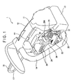
- Fig. 1 is a perspective view schematically illustrating an entire chain saw (portable work machine) 1 according to the exemplary embodiment.
- Fig. 2 is a perspective view illustrating a primary portion of the chain saw 1.
- Fig. 3 is a perspective view illustrating the chain saw 1 as viewed from a bottom side.
- Fig. 4 is a side view illustrating a part of the primary portion of the chainsaw 1 and
- Fig. 5 illustrates the part of the primary portion as viewed from a rear side.
- the chain saw 1 includes a top handle 12 above a body 11, and a handle 14 having one end connected to a front portion of the top handle 12 and the other end connected to a part of a fuel tank 13 in a rear bottom portion of the body 11.
- the fuel tank 13 according to the exemplary embodiment is integrated with the top handle 12.
- the body 11 includes a small two-cycle engine 15 having a crankcase (not shown) therein. Though not illustrated, a sprocket is pivotally supported on one end of a crankshaft 16 protruding from the engine 15 through a centrifugal clutch. A saw chain 18 is wound around the sprocket and a guide bar 17 provided beside the body 11 to be driven by the engine 15.
- a cooling fan 19 circumferentially having a plurality of fins is attached to the other end of the crankshaft 16.
- a fan case 21 having an intake opening 20 is provided surrounding the cooling fan 19.
- a volute that surrounds an outer circumference of the cooling fan 19 is provided on a rear surface of the fan case 21. The volute works as an air passage for feeding an intake cooling air into the engine 15.
- a communication passage forming section 24 having two partitions 22 and 23 is integrally provided on a surface of the fan case 21.
- An attachment 26 for attaching a cartridge type air cleaner 25 is provided in a vertical-sheet-shaped portion at a rear portion of the communication passage forming section 24.
- the attachment 26 is provided by a U-shaped consecutive protrusion, the protrusion defining an engaging groove against the sheet-shaped portion. The air cleaner 25 is slid from the above into the engaging groove of the attachment 26.
- the air cleaner 25 is disposed at a lateral side of the body 11 according to the exemplary embodiment.
- the lateral side portion of the body 11 has been used as a space for an intake communication passage that intercommunicates between proximity of a cooling fan and a carburetor chamber.
- the space for the intake communication passage is also used as a space for the air cleaner 25 according to the exemplary embodiment, the air cleaner 25 can be disposed without greatly increasing the size of the body 11 in which the air cleaner 25 is accommodated.
- the size of the top handle 12 can be reduced since it is not necessary that the air cleaner 25 is disposed in the top handle 12 in which a carburetor 36 is accommodated.
- FIG. 4 is a partial cutaway view of the air cleaner 25 of the above-described arrangement.
- the fan case 21 is covered with a cover 29 having a plurality of vents 28.
- a recoil starter (not shown) that is connected to and disconnected from the cooling fan 19 through a ratchet mechanism and a partition wall 30 protruding toward the fan case 21 are provided on a rear surface of the cover 29.
- a part of the partition wall 30 is abutted on the partitions 22 and 23 adjacent to the fan case 21. Other parts of the partition wall 30 protrude into the intake opening 20 of the fan case 21.
- An opening provided by the protruding parts and an inner circumference of the intake opening 20 is a suction opening 31 positioned opposite to a disk-shaped portion of the cooling fan 19 ( Fig. 4 ).
- a bottom circumference and a rear vertical circumference of the vertical-sheet-shaped portion of the fan case 21 along the U-shaped attachment 26 are covered with the cover 29.
- the cover 29 has an opening portion opposite to the air cleaner 25.
- An open-close lid 32 is attached to the opening portion.
- a hinge 33 is provided below the open-close lid 32 and rotatably and pivotally supported by the cover 29, by which the open-close lid 32 is opened and closed in a pivotal manner.
- An engaging claw 34 is provided on an upper side of the open-close lid 32, and engageable with an engaging hole 29A provided on an upper surface of the cover 29.
- the open-close lid 32 is opened and closed to attach and detach the air cleaner 25. More specifically, the open-close lid 32 is opened by disengaging the engaging claw 34 from the engaging hole 29A to provide an upper-side opening portion. Through this upper-side opening portion, the air cleaner 25 is pulled upwardly from the attachment 26 or is downwardly inserted into the attachment 26.
- a partition piece 35 protruding toward the fan case 21 is provided on a rear surface of the open-close lid 32.
- a distal end of the partition piece 35 is abutted on an upper end of the air cleaner 25.
- a space around the communication passage forming section 24 of the fan case 21 is covered with the cover 29 and the open-close lid 32 to be semi-hermetically sealed.
- This semi-hermetically sealed space provides an upper stream portion of an intake communication passage 37 (i.e., an upper stream relative to the air cleaner 25) that intercommunicates between the proximity of the cooling fan 19 and the carburetor 36 in the top handle 12.
- a gap 38 that communicates with the outside is purposely provided between the open-close lid 32 and the cover 29 adjacent to the hinge 33 of the open-close lid 32.
- a function of the gap 38 will be described later. Since the gap 38 is provided on a lower side of the open-close lid 32, seepage of rain water and the like is prevented.
- a first communication member 27 fitted to the opening 26A of the fan case 21 extends to a carburetor chamber 43 in the top handle 12 provided on an upper side.
- a carburetor chamber 43 in the top handle 12 provided on an upper side.
- an upper end of the first communication member 27 is fitted to a second communication member 39 formed in a hollow flat square box shape.
- the second communication member 39 includes an intake port 40 and an outlet port 41.
- the intake port 40 is connected to the upper end of the first communication member 27.
- the second communication member 39 is screwable into the carburetor 36.
- the outlet port 41 of the second communication member 39 is attached tightly to an intake passage 42 of the carburetor 36.
- An inner space that intercommunicates between the first and second communication members 27 and 39 is a closed space where air is not sucked except from the opening 26A.
- the first and second communication members 27 and 39 define a lower stream of the intake communication passage 37 (i.e., a lower stream relative to the air cleaner 25).
- the air cleaner 25 is disposed in the outside of the carburetor chamber 43 that includes the carburetor 36 and adjacent to a suction opening 31 in the intake communication passage 37.
- An intake air including dust that is sucked from the plurality of vents 28 by the cooling fan 19 is drawn in an axial direction of the cooling fan 19 through the intake opening 20 of the fan case 21, and then radially and outwardly fed into the engine 15 through an air-blow passage on an outer circumference of the engine 15 to cool the cylinder and the like.
- a part of the cooled air is fed into the engine 15 as air-fuel mixture through the suction opening 31, the intake communication passage 37, and the carburetor 36 by attraction of the engine 15.
- the dust in the cooled air sucked by the cooling fan 19 is fed into the air-blow passage through the suction opening 31 by centrifugal force after a stream direction of the cooled air is changed from an axial direction to a radial direction. Then, the dust is exhausted to the outside of the body 11 with the cooled air that cools the engine 15.
- the dust sucked from the suction opening 31 can be reduced. Also, frequent maintenance is not required because an amount of the dust caught by the air cleaner 25 is reduced.
- the lower stream space as viewed from the air cleaner 25 defines the closed space and directly communicates with the intake passage 42 of the carburetor 36. Therefore, the attraction of the engine 15 is not generated in the carburetor chamber 43 formed in the top handle 12 and dust in the air sucked from a little gap in the carburetor chamber 43 is reduced, which efficiently prevents the carburetor 36 from being soiled by the dust.
- the air cleaner 25 is disposed at the lateral side of the body 11 and adjacent to the cooling fan 19, the air cleaner 25 may be disposed adjacent to the guide bar 17.
- the air can be sucked by a centrifugal separation function of the cooling fan 19 and the dust can be removed by the negative pressure because the air cleaner 25 is disposed adjacent to the cooling fan 19. Therefore, it is preferably that the invention is carried out according to the exemplary embodiment.
- the invention is suitably applied to a portable work machine such as a top-handle-type small chain saw and a cutoff saw.
Landscapes
- Engineering & Computer Science (AREA)
- Chemical & Material Sciences (AREA)
- Combustion & Propulsion (AREA)
- Mechanical Engineering (AREA)
- General Engineering & Computer Science (AREA)
- Sawing (AREA)
- Harvester Elements (AREA)
- Cylinder Crankcases Of Internal Combustion Engines (AREA)
- Electrical Discharge Machining, Electrochemical Machining, And Combined Machining (AREA)
- Apparatuses For Bulk Treatment Of Fruits And Vegetables And Apparatuses For Preparing Feeds (AREA)
- Cleaning In General (AREA)
- Portable Power Tools In General (AREA)
Claims (1)
- Tragbare Arbeitsmaschine (1), die Folgendes umfasst:ein Gehäuse (11), in dem ein Motor (15) untergebracht wird,einen oberen Handgriff (12), der oberhalb des Gehäuses bereitgestellt wird,einen Vergaser (36), der in dem oberen Handgriff untergebracht ist, wobei der Vergaser ein Luft-Kraftstoff-Gemisch erzeugt, das dem Motor zugeführt werden soll,einen Luftfilter (25),einen Ansaug-Verbindungsdurchgang (37), der den Luftfilter und einen Ansaugdurchgang des Vergasers verbindet,eine Kurbelwelle (16) des Motors (15), die ein Ende hat, das auf einer seitlichen Seite des Gehäuses (11) angeordnet ist, undeine Abdeckung (29), die auf der seitlichen Seite des Gehäuses (11) bereitgestellt wird,dadurch gekennzeichnet, dassein Auf-Zu-Deckel (32) in einem Öffnungsabschnitt der Abdeckung bereitgestellt wird undder Luftfilter (25) auf der seitlichen Seite des Gehäuses bereitgestellt wird, abgedeckt mit dem Auf-Zu-Deckel, wobeider Auf-Zu-Deckel (32) durch ein Scharnier (33), das auf einer unteren Seite des Auf-Zu-Deckels bereitgestellt wird, drehbar und schwenkbar durch die Abdeckung (29) getragen wird, undder Luftfilter (25) durch einen oberen Öffnungsabschnitt, der durch das Öffnen des Auf-Zu-Deckels gebildet wird, in Vertikalrichtung in das Gehäuse (11) eingesetzt und aus demselben entnommen wird.
Applications Claiming Priority (2)
| Application Number | Priority Date | Filing Date | Title |
|---|---|---|---|
| JP2006137627A JP2007309165A (ja) | 2006-05-17 | 2006-05-17 | 携帯型作業機 |
| PCT/JP2007/060120 WO2007132914A1 (ja) | 2006-05-17 | 2007-05-17 | 携帯型作業機 |
Publications (3)
| Publication Number | Publication Date |
|---|---|
| EP2020490A1 EP2020490A1 (de) | 2009-02-04 |
| EP2020490A4 EP2020490A4 (de) | 2010-07-14 |
| EP2020490B1 true EP2020490B1 (de) | 2012-03-28 |
Family
ID=38694000
Family Applications (1)
| Application Number | Title | Priority Date | Filing Date |
|---|---|---|---|
| EP07743555A Not-in-force EP2020490B1 (de) | 2006-05-17 | 2007-05-17 | Tragbare arbeitsmaschine |
Country Status (7)
| Country | Link |
|---|---|
| US (1) | US8302579B2 (de) |
| EP (1) | EP2020490B1 (de) |
| JP (1) | JP2007309165A (de) |
| CN (1) | CN101449038B (de) |
| AT (1) | ATE551514T1 (de) |
| TW (1) | TW200800532A (de) |
| WO (1) | WO2007132914A1 (de) |
Families Citing this family (4)
| Publication number | Priority date | Publication date | Assignee | Title |
|---|---|---|---|---|
| JP5555522B2 (ja) * | 2010-03-29 | 2014-07-23 | 本田技研工業株式会社 | 手持ち式作業機 |
| JP6401651B2 (ja) * | 2015-04-15 | 2018-10-10 | 株式会社やまびこ | 動力作業機 |
| EP3456481B1 (de) * | 2017-09-15 | 2020-06-10 | Andreas Stihl AG & Co. KG | Handgeführtes arbeitsgerät |
| US12140110B2 (en) * | 2021-03-12 | 2024-11-12 | Honda Motor Co., Ltd. | Internal combustion engine |
Family Cites Families (22)
| Publication number | Priority date | Publication date | Assignee | Title |
|---|---|---|---|---|
| US4266515A (en) * | 1978-09-27 | 1981-05-12 | Roper Corporation | Engine power pack assembly having anti-vibration features |
| JPS57123955U (de) * | 1980-12-26 | 1982-08-02 | ||
| JPS57123955A (en) | 1981-01-26 | 1982-08-02 | Mitsubishi Metal Corp | Free graphite dispersion type sintered sliding iron material and its manufacture |
| JPH0340564Y2 (de) | 1984-09-26 | 1991-08-27 | ||
| US4876797A (en) * | 1989-01-17 | 1989-10-31 | Alvaro Zapata | Reduced vibration portable gas operated hand saw |
| JPH0330620A (ja) * | 1989-06-28 | 1991-02-08 | Naoto Okazaki | 魚信感知式自動アワセ装置 |
| DE3935361C2 (de) * | 1989-10-24 | 1998-12-24 | Stihl Maschf Andreas | Arbeitsgerät wie Motorkettensäge oder dgl., insbesondere Einhandkettensäge |
| DE4120874C2 (de) * | 1991-06-21 | 2002-02-07 | Stihl Maschf Andreas | Gerätegehäuse für ein Arbeitsgerät, insbesondere eine Motorkettensäge |
| JP3076436B2 (ja) | 1992-01-21 | 2000-08-14 | 株式会社共立 | 内燃機関の空気吸入装置 |
| JP2876378B2 (ja) * | 1993-07-06 | 1999-03-31 | 本田技研工業株式会社 | 歩行型耕耘機 |
| US5367988A (en) * | 1993-09-01 | 1994-11-29 | Wci-Outdoor Products, Inc. | Dynamic air cleaner and carburetor pressurization system for air cooled internal combustion engines |
| DE4404465B4 (de) * | 1994-02-11 | 2007-09-27 | Fa. Andreas Stihl | Handgeführtes Arbeitsgerät mit einem Filterkasten |
| JP3030620U (ja) | 1996-04-25 | 1996-11-01 | ジャパンハックス株式会社 | 携帯用エンジンカッターのエアフィルタ装置 |
| JP3961087B2 (ja) * | 1997-10-24 | 2007-08-15 | 株式会社共立 | エアークリーナ |
| DE19831496A1 (de) | 1998-07-14 | 2000-01-20 | Stihl Maschf Andreas | Schnappverschluß |
| JP3822384B2 (ja) * | 1999-06-04 | 2006-09-20 | 株式会社共立 | 携帯型動力作業機 |
| JP4071413B2 (ja) * | 2000-01-27 | 2008-04-02 | 株式会社共立 | 携帯型動力作業機 |
| JP2001205603A (ja) * | 2000-01-27 | 2001-07-31 | Kioritz Corp | 携帯型動力作業機 |
| DE10211874A1 (de) * | 2002-03-18 | 2003-10-02 | Stihl Maschf Andreas | Tragbares, handgeführtes Arbeitsgerät |
| JP3720787B2 (ja) | 2002-04-02 | 2005-11-30 | 株式会社共立 | 携帯型動力作業機 |
| JP3587825B2 (ja) * | 2002-06-03 | 2004-11-10 | 株式会社共立 | 携帯型動力作業機 |
| JP2005083241A (ja) * | 2003-09-08 | 2005-03-31 | Kioritz Corp | 携帯型動力作業機 |
-
2006
- 2006-05-17 JP JP2006137627A patent/JP2007309165A/ja active Pending
-
2007
- 2007-05-17 WO PCT/JP2007/060120 patent/WO2007132914A1/ja not_active Ceased
- 2007-05-17 US US12/227,415 patent/US8302579B2/en not_active Expired - Fee Related
- 2007-05-17 AT AT07743555T patent/ATE551514T1/de active
- 2007-05-17 CN CN2007800178873A patent/CN101449038B/zh not_active Expired - Fee Related
- 2007-05-17 EP EP07743555A patent/EP2020490B1/de not_active Not-in-force
- 2007-05-17 TW TW096117541A patent/TW200800532A/zh unknown
Also Published As
| Publication number | Publication date |
|---|---|
| US20090235538A1 (en) | 2009-09-24 |
| JP2007309165A (ja) | 2007-11-29 |
| CN101449038B (zh) | 2011-01-26 |
| TW200800532A (en) | 2008-01-01 |
| CN101449038A (zh) | 2009-06-03 |
| ATE551514T1 (de) | 2012-04-15 |
| WO2007132914A1 (ja) | 2007-11-22 |
| EP2020490A4 (de) | 2010-07-14 |
| EP2020490A1 (de) | 2009-02-04 |
| US8302579B2 (en) | 2012-11-06 |
Similar Documents
| Publication | Publication Date | Title |
|---|---|---|
| US7007660B2 (en) | Portable power working machine | |
| JP3665220B2 (ja) | 携帯型動力作業機 | |
| CN101737208B (zh) | 发动机工具 | |
| EP2670961B1 (de) | Zweitaktmotor mit schichtspülung | |
| EP2020490B1 (de) | Tragbare arbeitsmaschine | |
| US11085394B2 (en) | Engine | |
| US8683706B2 (en) | Engine-driven cutter | |
| JP3587825B2 (ja) | 携帯型動力作業機 | |
| JP2009299606A (ja) | エンジン工具 | |
| US20030183208A1 (en) | Portable power working machine | |
| US9115645B2 (en) | Engine-driven cutter | |
| US6464018B1 (en) | Portable handheld drilling machine having an internal combustion engine | |
| CN106837546A (zh) | 通用发动机 | |
| JP2007309166A (ja) | 携帯型作業機 | |
| WO2012090256A1 (en) | Two-stroke engine | |
| JP2008101547A (ja) | エンジン | |
| JP2014020313A (ja) | 携帯型作業機 | |
| JP2007218186A (ja) | 携帯型送風作業機のエンジン冷却構造 | |
| JP5737610B2 (ja) | 携帯型作業機 | |
| JP2009018359A (ja) | チェーンソー | |
| JP6823226B1 (ja) | 吸気部材の開閉機構 | |
| JPH06917Y2 (ja) | 茶刈機用エンジン部の除塵装置 | |
| JP6165666B2 (ja) | 携帯型作業機のキャブレタ取付け構造及び取付け方法 |
Legal Events
| Date | Code | Title | Description |
|---|---|---|---|
| PUAI | Public reference made under article 153(3) epc to a published international application that has entered the european phase |
Free format text: ORIGINAL CODE: 0009012 |
|
| 17P | Request for examination filed |
Effective date: 20081217 |
|
| AK | Designated contracting states |
Kind code of ref document: A1 Designated state(s): AT BE BG CH CY CZ DE DK EE ES FI FR GB GR HU IE IS IT LI LT LU LV MC MT NL PL PT RO SE SI SK TR |
|
| AX | Request for extension of the european patent |
Extension state: AL BA HR MK RS |
|
| A4 | Supplementary search report drawn up and despatched |
Effective date: 20100616 |
|
| 17Q | First examination report despatched |
Effective date: 20110311 |
|
| GRAP | Despatch of communication of intention to grant a patent |
Free format text: ORIGINAL CODE: EPIDOSNIGR1 |
|
| DAX | Request for extension of the european patent (deleted) | ||
| GRAS | Grant fee paid |
Free format text: ORIGINAL CODE: EPIDOSNIGR3 |
|
| GRAA | (expected) grant |
Free format text: ORIGINAL CODE: 0009210 |
|
| AK | Designated contracting states |
Kind code of ref document: B1 Designated state(s): AT BE BG CH CY CZ DE DK EE ES FI FR GB GR HU IE IS IT LI LT LU LV MC MT NL PL PT RO SE SI SK TR |
|
| REG | Reference to a national code |
Ref country code: GB Ref legal event code: FG4D |
|
| REG | Reference to a national code |
Ref country code: CH Ref legal event code: EP |
|
| REG | Reference to a national code |
Ref country code: AT Ref legal event code: REF Ref document number: 551514 Country of ref document: AT Kind code of ref document: T Effective date: 20120415 |
|
| REG | Reference to a national code |
Ref country code: IE Ref legal event code: FG4D |
|
| REG | Reference to a national code |
Ref country code: DE Ref legal event code: R096 Ref document number: 602007021625 Country of ref document: DE Effective date: 20120524 |
|
| REG | Reference to a national code |
Ref country code: NL Ref legal event code: VDEP Effective date: 20120328 |
|
| PG25 | Lapsed in a contracting state [announced via postgrant information from national office to epo] |
Ref country code: LT Free format text: LAPSE BECAUSE OF FAILURE TO SUBMIT A TRANSLATION OF THE DESCRIPTION OR TO PAY THE FEE WITHIN THE PRESCRIBED TIME-LIMIT Effective date: 20120328 |
|
| LTIE | Lt: invalidation of european patent or patent extension |
Effective date: 20120328 |
|
| PG25 | Lapsed in a contracting state [announced via postgrant information from national office to epo] |
Ref country code: LV Free format text: LAPSE BECAUSE OF FAILURE TO SUBMIT A TRANSLATION OF THE DESCRIPTION OR TO PAY THE FEE WITHIN THE PRESCRIBED TIME-LIMIT Effective date: 20120328 Ref country code: FI Free format text: LAPSE BECAUSE OF FAILURE TO SUBMIT A TRANSLATION OF THE DESCRIPTION OR TO PAY THE FEE WITHIN THE PRESCRIBED TIME-LIMIT Effective date: 20120328 Ref country code: GR Free format text: LAPSE BECAUSE OF FAILURE TO SUBMIT A TRANSLATION OF THE DESCRIPTION OR TO PAY THE FEE WITHIN THE PRESCRIBED TIME-LIMIT Effective date: 20120629 |
|
| REG | Reference to a national code |
Ref country code: AT Ref legal event code: MK05 Ref document number: 551514 Country of ref document: AT Kind code of ref document: T Effective date: 20120328 |
|
| PG25 | Lapsed in a contracting state [announced via postgrant information from national office to epo] |
Ref country code: CY Free format text: LAPSE BECAUSE OF FAILURE TO SUBMIT A TRANSLATION OF THE DESCRIPTION OR TO PAY THE FEE WITHIN THE PRESCRIBED TIME-LIMIT Effective date: 20120328 |
|
| PG25 | Lapsed in a contracting state [announced via postgrant information from national office to epo] |
Ref country code: SE Free format text: LAPSE BECAUSE OF FAILURE TO SUBMIT A TRANSLATION OF THE DESCRIPTION OR TO PAY THE FEE WITHIN THE PRESCRIBED TIME-LIMIT Effective date: 20120328 Ref country code: RO Free format text: LAPSE BECAUSE OF FAILURE TO SUBMIT A TRANSLATION OF THE DESCRIPTION OR TO PAY THE FEE WITHIN THE PRESCRIBED TIME-LIMIT Effective date: 20120328 Ref country code: CZ Free format text: LAPSE BECAUSE OF FAILURE TO SUBMIT A TRANSLATION OF THE DESCRIPTION OR TO PAY THE FEE WITHIN THE PRESCRIBED TIME-LIMIT Effective date: 20120328 Ref country code: IS Free format text: LAPSE BECAUSE OF FAILURE TO SUBMIT A TRANSLATION OF THE DESCRIPTION OR TO PAY THE FEE WITHIN THE PRESCRIBED TIME-LIMIT Effective date: 20120728 Ref country code: EE Free format text: LAPSE BECAUSE OF FAILURE TO SUBMIT A TRANSLATION OF THE DESCRIPTION OR TO PAY THE FEE WITHIN THE PRESCRIBED TIME-LIMIT Effective date: 20120328 Ref country code: PL Free format text: LAPSE BECAUSE OF FAILURE TO SUBMIT A TRANSLATION OF THE DESCRIPTION OR TO PAY THE FEE WITHIN THE PRESCRIBED TIME-LIMIT Effective date: 20120328 Ref country code: BE Free format text: LAPSE BECAUSE OF FAILURE TO SUBMIT A TRANSLATION OF THE DESCRIPTION OR TO PAY THE FEE WITHIN THE PRESCRIBED TIME-LIMIT Effective date: 20120328 Ref country code: SI Free format text: LAPSE BECAUSE OF FAILURE TO SUBMIT A TRANSLATION OF THE DESCRIPTION OR TO PAY THE FEE WITHIN THE PRESCRIBED TIME-LIMIT Effective date: 20120328 |
|
| PG25 | Lapsed in a contracting state [announced via postgrant information from national office to epo] |
Ref country code: SK Free format text: LAPSE BECAUSE OF FAILURE TO SUBMIT A TRANSLATION OF THE DESCRIPTION OR TO PAY THE FEE WITHIN THE PRESCRIBED TIME-LIMIT Effective date: 20120328 Ref country code: PT Free format text: LAPSE BECAUSE OF FAILURE TO SUBMIT A TRANSLATION OF THE DESCRIPTION OR TO PAY THE FEE WITHIN THE PRESCRIBED TIME-LIMIT Effective date: 20120730 |
|
| PG25 | Lapsed in a contracting state [announced via postgrant information from national office to epo] |
Ref country code: MC Free format text: LAPSE BECAUSE OF NON-PAYMENT OF DUE FEES Effective date: 20120531 |
|
| REG | Reference to a national code |
Ref country code: CH Ref legal event code: PL |
|
| PG25 | Lapsed in a contracting state [announced via postgrant information from national office to epo] |
Ref country code: NL Free format text: LAPSE BECAUSE OF FAILURE TO SUBMIT A TRANSLATION OF THE DESCRIPTION OR TO PAY THE FEE WITHIN THE PRESCRIBED TIME-LIMIT Effective date: 20120328 Ref country code: CH Free format text: LAPSE BECAUSE OF NON-PAYMENT OF DUE FEES Effective date: 20120531 Ref country code: AT Free format text: LAPSE BECAUSE OF FAILURE TO SUBMIT A TRANSLATION OF THE DESCRIPTION OR TO PAY THE FEE WITHIN THE PRESCRIBED TIME-LIMIT Effective date: 20120328 Ref country code: DK Free format text: LAPSE BECAUSE OF FAILURE TO SUBMIT A TRANSLATION OF THE DESCRIPTION OR TO PAY THE FEE WITHIN THE PRESCRIBED TIME-LIMIT Effective date: 20120328 Ref country code: LI Free format text: LAPSE BECAUSE OF NON-PAYMENT OF DUE FEES Effective date: 20120531 |
|
| PLBE | No opposition filed within time limit |
Free format text: ORIGINAL CODE: 0009261 |
|
| STAA | Information on the status of an ep patent application or granted ep patent |
Free format text: STATUS: NO OPPOSITION FILED WITHIN TIME LIMIT |
|
| REG | Reference to a national code |
Ref country code: IE Ref legal event code: MM4A |
|
| 26N | No opposition filed |
Effective date: 20130103 |
|
| REG | Reference to a national code |
Ref country code: DE Ref legal event code: R097 Ref document number: 602007021625 Country of ref document: DE Effective date: 20130103 |
|
| PG25 | Lapsed in a contracting state [announced via postgrant information from national office to epo] |
Ref country code: IE Free format text: LAPSE BECAUSE OF NON-PAYMENT OF DUE FEES Effective date: 20120517 Ref country code: ES Free format text: LAPSE BECAUSE OF FAILURE TO SUBMIT A TRANSLATION OF THE DESCRIPTION OR TO PAY THE FEE WITHIN THE PRESCRIBED TIME-LIMIT Effective date: 20120709 |
|
| PG25 | Lapsed in a contracting state [announced via postgrant information from national office to epo] |
Ref country code: MT Free format text: LAPSE BECAUSE OF FAILURE TO SUBMIT A TRANSLATION OF THE DESCRIPTION OR TO PAY THE FEE WITHIN THE PRESCRIBED TIME-LIMIT Effective date: 20120328 Ref country code: BG Free format text: LAPSE BECAUSE OF FAILURE TO SUBMIT A TRANSLATION OF THE DESCRIPTION OR TO PAY THE FEE WITHIN THE PRESCRIBED TIME-LIMIT Effective date: 20120628 |
|
| PG25 | Lapsed in a contracting state [announced via postgrant information from national office to epo] |
Ref country code: TR Free format text: LAPSE BECAUSE OF FAILURE TO SUBMIT A TRANSLATION OF THE DESCRIPTION OR TO PAY THE FEE WITHIN THE PRESCRIBED TIME-LIMIT Effective date: 20120328 |
|
| PG25 | Lapsed in a contracting state [announced via postgrant information from national office to epo] |
Ref country code: LU Free format text: LAPSE BECAUSE OF NON-PAYMENT OF DUE FEES Effective date: 20120517 |
|
| PG25 | Lapsed in a contracting state [announced via postgrant information from national office to epo] |
Ref country code: HU Free format text: LAPSE BECAUSE OF FAILURE TO SUBMIT A TRANSLATION OF THE DESCRIPTION OR TO PAY THE FEE WITHIN THE PRESCRIBED TIME-LIMIT Effective date: 20070517 |
|
| REG | Reference to a national code |
Ref country code: FR Ref legal event code: PLFP Year of fee payment: 10 |
|
| REG | Reference to a national code |
Ref country code: FR Ref legal event code: PLFP Year of fee payment: 11 |
|
| REG | Reference to a national code |
Ref country code: FR Ref legal event code: PLFP Year of fee payment: 12 |
|
| PGFP | Annual fee paid to national office [announced via postgrant information from national office to epo] |
Ref country code: FR Payment date: 20180502 Year of fee payment: 12 Ref country code: IT Payment date: 20180323 Year of fee payment: 12 |
|
| PGFP | Annual fee paid to national office [announced via postgrant information from national office to epo] |
Ref country code: GB Payment date: 20180420 Year of fee payment: 12 |
|
| GBPC | Gb: european patent ceased through non-payment of renewal fee |
Effective date: 20190517 |
|
| PG25 | Lapsed in a contracting state [announced via postgrant information from national office to epo] |
Ref country code: GB Free format text: LAPSE BECAUSE OF NON-PAYMENT OF DUE FEES Effective date: 20190517 Ref country code: IT Free format text: LAPSE BECAUSE OF NON-PAYMENT OF DUE FEES Effective date: 20190517 |
|
| PG25 | Lapsed in a contracting state [announced via postgrant information from national office to epo] |
Ref country code: FR Free format text: LAPSE BECAUSE OF NON-PAYMENT OF DUE FEES Effective date: 20190531 |
|
| PGFP | Annual fee paid to national office [announced via postgrant information from national office to epo] |
Ref country code: DE Payment date: 20220406 Year of fee payment: 16 |
|
| REG | Reference to a national code |
Ref country code: DE Ref legal event code: R119 Ref document number: 602007021625 Country of ref document: DE |
|
| PG25 | Lapsed in a contracting state [announced via postgrant information from national office to epo] |
Ref country code: DE Free format text: LAPSE BECAUSE OF NON-PAYMENT OF DUE FEES Effective date: 20231201 |