EP2018974A1 - Druckband und kassette zur druckverwendung - Google Patents
Druckband und kassette zur druckverwendung Download PDFInfo
- Publication number
- EP2018974A1 EP2018974A1 EP07742066A EP07742066A EP2018974A1 EP 2018974 A1 EP2018974 A1 EP 2018974A1 EP 07742066 A EP07742066 A EP 07742066A EP 07742066 A EP07742066 A EP 07742066A EP 2018974 A1 EP2018974 A1 EP 2018974A1
- Authority
- EP
- European Patent Office
- Prior art keywords
- tape
- base material
- printed medium
- adhesive layer
- Prior art date
- Legal status (The legal status is an assumption and is not a legal conclusion. Google has not performed a legal analysis and makes no representation as to the accuracy of the status listed.)
- Granted
Links
Images


Classifications
-
- B—PERFORMING OPERATIONS; TRANSPORTING
- B41—PRINTING; LINING MACHINES; TYPEWRITERS; STAMPS
- B41J—TYPEWRITERS; SELECTIVE PRINTING MECHANISMS, i.e. MECHANISMS PRINTING OTHERWISE THAN FROM A FORME; CORRECTION OF TYPOGRAPHICAL ERRORS
- B41J32/00—Ink-ribbon cartridges
-
- B—PERFORMING OPERATIONS; TRANSPORTING
- B41—PRINTING; LINING MACHINES; TYPEWRITERS; STAMPS
- B41J—TYPEWRITERS; SELECTIVE PRINTING MECHANISMS, i.e. MECHANISMS PRINTING OTHERWISE THAN FROM A FORME; CORRECTION OF TYPOGRAPHICAL ERRORS
- B41J15/00—Devices or arrangements of selective printing mechanisms, e.g. ink-jet printers or thermal printers, specially adapted for supporting or handling copy material in continuous form, e.g. webs
- B41J15/04—Supporting, feeding, or guiding devices; Mountings for web rolls or spindles
- B41J15/044—Cassettes or cartridges containing continuous copy material, tape, for setting into printing devices
-
- B—PERFORMING OPERATIONS; TRANSPORTING
- B41—PRINTING; LINING MACHINES; TYPEWRITERS; STAMPS
- B41J—TYPEWRITERS; SELECTIVE PRINTING MECHANISMS, i.e. MECHANISMS PRINTING OTHERWISE THAN FROM A FORME; CORRECTION OF TYPOGRAPHICAL ERRORS
- B41J17/00—Mechanisms for manipulating page-width impression-transfer material, e.g. carbon paper
- B41J17/32—Detachable carriers or holders for impression-transfer material mechanism
Definitions
- the disclosure relates to a print cassette for producing either a laminated-type print tape (hereinafter, referred to as a "laminated tape”) or a receptor-type print tape (hereinafter, referred to as a "non-laminated tape").
- laminated-type print tape hereinafter, referred to as a "laminated tape”
- receptor-type print tape hereinafter, referred to as a "non-laminated tape”
- a tape printer in which a print cassette is installed has been used to produce a print tape on which characters and the like are printed.
- One of the various print tapes which can be produced in the tape printer is a "laminated tape" made of a film tape having a printing backside surface to which an adhesive tape adhered (see, for example, patent document 1).
- a tape printer in which a print cassette is installed has been used to produce a print tape on which characters and the like are printed.
- One of the various print tapes which can be produced in the tape printer is a "non-laminated tape" made of a receptor sheet and a separator sheet adhered to each other with an adhesive agent (see, for example, patent document 2).
- the thickness of its film tape is approximately 38 ⁇ m and the thickness of its adhesive tape is approximately 50 ⁇ m to 60 ⁇ m (thickness of its base material: 12 ⁇ m to 20 ⁇ m), so that the thickness of a print tape is approximately 100 ⁇ m.
- the conventional "laminated tape” is stuck to a curved face of an adherend, the conventional “laminated tape” would be likely to gradually come unstuck from the curved surface of the adherend due to insufficient elasticity or the like resulting from the thickness of the print tape.
- a conventional "non-laminated tape” has a base film composing a receptor sheet as thick as 38 ⁇ m or more. Therefore, an outline of a receptor sheet tends to be visually identified when the conventional "non-laminated tape" is stuck to an adherend, even when a receptor sheet is arranged to be transparent to be invisible so that printed characters and the like can be emphasized. Further, when the conventional "non-laminated tape" is stuck to a curved surface of an adherend, it would be likely to gradually come unstuck from the curved surface of the adherend due to insufficient elasticity or the like resulting from the thickness of a to-be-printed medium.
- the film tape or the base film is requested to be thin, but a film tape or a base film just arranged to be thin may have a bad effect on a feeding performance of the film tape in the print cassette and handling of a print tape when the print tape is stuck to the adherend.
- the disclosure has been made in view of the above circumstances and has an object to overcome the above problems and to provide a print cassette for producing a print tape comprising a structure which can avoid a bad effect on a feeding performance of a film tape in the print cassette and handling of a print tape when stuck to an adherend even when an adopted to-be-printed medium is a thin-film;
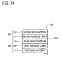
- a print tape comprising: a first base material; a to-be-printed medium; a first adhesive layer formed of a first adhesive agent interposed between the first base material and the to-be-printed medium; a second base material; and a second adhesive layer formed of a second adhesive agent applied to the second base material, wherein the to-be-printed medium adopts a rear face of the face to which the first adhesive layer adheres as its printing surface.
- adhesion force between the first adhesive layer and the to-be-printed medium is smaller than adhesion force between the second adhesive layer and the to-be-printed medium.
- a print tape comprising: a first base material; a to-be-printed medium; a first adhesive layer formed of a first adhesive agent interposed between the first base material and the to-be-printed medium; a third base material; a third adhesive layer formed of a third adhesive agent applied to a first face side of the third base material; a fourth base material; and a fourth adhesive layer formed of a fourth adhesive agent interposed between a second face side of the third base material and the fourth base material, wherein the to-be-printed medium adopts a rear face of the face to which the first adhesive layer adheres as its printing surface.
- adhesion force between the first adhesive layer and the to-be-printed medium is smaller than adhesion force between the third adhesive layer and the to-be-printed medium.
- the print tape according to claim 2 or 4 wherein the first adhesive agent is dispersed uniformly in a predetermined pattern.
- thermosensitive coloring agent is made on the printing surface side of the to-be-printed medium.
- the print tape according to claim 10 wherein the first base material is provided preliminarily with a mark indicating the up-down direction or right-left direction of the printing surface of the to-be-printed medium.
- a print cassette accommodating a first tape and a second tape, designed to be mounted on a print device having a printing position
- the first tape includes: a first base material; a to-be-printed medium; and a first adhesive layer formed of a first adhesive agent interposed between the first base material and the to-be-printed medium
- the second tape includes: a second base material; and a second adhesive layer formed of a second adhesive agent applied to the second base material, and the to-be-printed medium adopts a rear face of the face to which the first adhesive layer adheres as its printing surface.
- adhesion force between the first adhesive layer and the to-be-printed medium is smaller than adhesion force between the second adhesive layer and the to-be-printed medium.
- a print cassette accommodating a first tape and a third tape, designed to be mounted on a print device having a printing position
- the first tape includes: a first base material; a to-be-printed medium; and a first adhesive layer formed of a first adhesive agent interposed between the first base material and the to-be-printed medium
- the third tape includes: a third base material; a third adhesive layer formed of a third adhesive agent applied to a first face side of the third base material; a fourth base material; and a fourth adhesive layer formed of a fourth adhesive agent interposed between a second face side of the third base material and the fourth base material, wherein the to-be-printed medium adopts a rear face of the face to which the first adhesive layer adheres as its printing surface.
- adhesion force between the first adhesive layer and the to-be-printed medium is smaller than adhesion force between the third adhesive layer and the to-be-printed medium.
- thermosensitive coloring agent is made on the printing surface side of the to-be-printed medium.
- the print cassette according to any one of claims 15 to 20, further accommodating an ink ribbon having an ink face, wherein the ink face of the ink ribbon and the printing surface of the to-be-printed medium face each other at the print position of the print device.
- the print cassette according to claim 21 wherein a print head is disposed at the printing position of the print device, the width of the ink ribbon is wider than the width of the to-be-printed medium, and when the printing surface of the to-be-printed medium faces the printing head of the print device through the ink face of the ink ribbon, the to-be-printed medium is covered with the ink ribbon so that the to-be-printed medium is hidden with respect to the print head of the print device.
- a print cassette in which a both sides adhesive tape, an ink ribbon and a multilayer laminated tape are wound individually and mounted on a print device
- the multilayer laminated tape includes: a handling auxiliary film which is a base material; a thin laminated film having a printing surface to which ink of the ink ribbon is to be transferred on a first face side thereof; and a weak adhesive layer formed of a weak adhesive agent which is applied between the handling auxiliary film and a second face side of the thin laminated film and used for adhering such that the weak adhesive layer is separable from the thin laminated film
- the both sides adhesive tape includes: a base film; a first adhesive layer formed of a first adhesive agent which is applied to a first face side of the base film and used for adhering a first face side of the thin laminated film; a release sheet adhered to a second face side of the base film; and a second adhesive layer which is applied between the second face side of the base film and the release sheet and
- a print cassette in which a monolayer adhesive tape, an ink ribbon and a multilayer laminated tape are wound individually and mounted on a print device
- the multilayer laminated tape includes: a handling auxiliary film which is a base material; a thin laminated film having a printing surface to which ink of the ink ribbon is to be transferred on a first face side thereof; and a weak adhesive layer formed of a weak adhesive agent which is applied between the handling auxiliary film and a second face side of the thin laminated film and used for adhering such that the weak adhesive layer is separable from the thin laminated film
- the monolayer adhesive tape includes: a release sheet; and a third adhesive layer which is applied to a first face side of the release sheet and formed of a third adhesive agent, wherein the print tape is formed when the monolayer adhesive tape and the multilayer laminated tape adhered together with the third adhesive layer and discharged from the print device.
- the print cassette according to claim 30 or 31 wherein the width of the handling auxiliary film and the width of the thin laminated film are different from each other.
- the print cassette according to claim 33 wherein the handling auxiliary film is colored or patterned.
- the handling auxiliary film is provided preliminarily with a mark indicating the up-down direction or right-left direction of the printing surface of the thin laminated film.
- the second base material adheres to the printing surface of the to-be-printed medium with the second adhesive layer. Then, the second base material is removed from the to-be-printed medium and, with the exposed second adhesive layer stuck to an adherend, the first base material which adhered to the to-be-printed medium with the first adhesive layer is removed. As a result, the first adhesive layer is separated together with the first base material from the to-be-printed medium and then, the printing surface of the to-be-printed medium is stuck to the adherend with the second adhesive layer. Consequently, the "laminated tape" can be stuck to the adherend.
- the third base material adheres to the printing surface of the to-be-printed medium with the third adhesive layer.
- the fourth base material is removed from the third base material and, with the exposed fourth adhesive layer stuck to an adherend, the first base material which adhered to the to-be-printed medium with the first adhesive layer is removed from the to-be-printed medium.
- the first adhesive layer is separated together with the first base material from the to-be-printed medium and then, the printing surface side of the to-be-printed medium is in a state of adhering to the third base material with the third adhesive agent, the third base material is stuck to the adherend with the fourth adhesive layer. Consequently, the "laminated tape" can be stuck to the adherend.
- the to-be-printed medium adhered to the first base material with the first adhesive layer can thus keep the rigidity at least by the thickness of the first base material.
- the to-be-printed medium When the to-be-printed medium is stuck to the adherend, the first base material adhered to the to-be-printed medium, so that the to-be-printed medium can thus keep the rigidity at least by the thickness of the first base material.
- the work of sticking the "laminated tape” to the adherend securely can be carried out.
- the to-be-printed medium when the to-be-printed medium is stuck to the adherend, the first base material adhered to the to-be-printed medium with the first adhesive layer.
- the to-be-printed medium can thus keep the rigidity at least by the thickness of the first base material and however thin the to-be-printed medium is, the work of sticking the to-be-printed medium to the adherend securely can be carried out.
- the first adhesive agent for forming the first adhesive layer is dispersed uniformly in a predetermined pattern. Therefore, even if the to-be-printed medium is stuck to the adherend, the clue for releasing the first base material from the to-be-printed medium is easy to make and after that, the first base material is easy to remove from the to-be-printed medium.
- Examples of the predetermined pattern include a striped pattern, a grid pattern, and a polka-dot pattern.
- the print tape of the present disclosure includes, for example, a thermosensitive type according to the disclosure of claim 6 and a thermal transfer type according to the disclosure of claim 7.
- the width of the first base material and the width of the to-be-printed medium are different from each other, the first base material can be distinguished easily and it is convenient when releasing the first base material from the to-be-printed medium.
- the first base material is transparent, printed characters on the printing surface of the to-be-printed medium can be recognized visually and the up-down direction of the print tape can be confirmed. Thus, it is convenient when sticking the print tape to the adherend.
- the first base material adhered to the to-be-printed medium with the first adhesive layer is opaque, and thus has the hiding performance. Accordingly, the to-be-printed medium cannot be recognized visually via the first base material, so that the print content of the to-be-printed medium can be hidden. Consequently, the security effect to the print content of the to-be-printed medium is exerted.
- the first base material is provided preliminarily with the mark indicating the up-down direction or right-left direction of the printing surface of the to-be-printed medium.
- the first base material can be removed from the to-be-printed medium easily by the half cut.
- the second base material adhered to the to-be-printed medium with the second adhesive layer adhered to the to-be-printed medium with the second adhesive layer. Then, when part of the second base material is removed from the to-be-printed medium along the half cut in order to stick the to-be-printed medium to the adherend, part of the second adhesive layer is exposed, so that part of the to-be-printed medium can be stuck to the adherend with the part of the second adhesive layer. At this time, the left portion of the second base material still adhered to the to-be-printed medium and the to-be-printed medium can thus keep the rigidity by the stiffness of the left portion of the second base material. Consequently, however thin the to-be-printed medium is, the work of sticking part of the to-be-printed medium to the adherend securely without generation of wrinkles can be carried out.
- the left portion of the second adhesive layer is exposed when the left portion of the second base material is removed from the to-be-printed medium, the left portion of the to-be-printed medium can be stuck to the adherend with the left portion of the second adhesive layer.
- the to-be-printed medium can thus keep the tension by part of the to-be-printed medium stuck to the adherend. Consequently, however thin the to-be-printed medium is, the work of sticking the left portion of the to-be-printed medium to the adherend securely without generation of wrinkles can be carried out.
- the to-be-printed medium can be stuck to the adherend step by step. This facilitates the work of securely sticking the to-be-printed medium to the adherend without generation of wrinkles.
- the third base material adhered to the to-be-printed medium with the third adhesive layer so that the to-be-printed medium and the third base material are integrally formed. Then, when part of the fourth base material adhered to the third base material with the fourth adhesive layer is removed from the third base material along the half cut in order to stick the to-be-printed medium to the adherend, part of the fourth adhesive layer is exposed, so that part of the to-be-printed medium integrated with the third base material can be stuck to the adherend with the part of the fourth adhesive layer.
- the left portion of the fourth base material still adhered to the to-be-printed medium via the third base material and the to-be-printed medium can thus keep the rigidity by the stiffness of the left portion of the fourth base material. Consequently, however thin the to-be-printed medium is, the work of sticking part of the to-be-printed medium to the adherend securely without generation of wrinkles can be carried out.
- the left portion of the fourth adhesive layer is exposed when the left portion of the fourth base material is removed from the third base material integrated with the to-be-printed medium, the left portion of the to-be-printed medium integrated with the third base material can be stuck to the adherend with the left portion of the fourth adhesive layer.
- the to-be-printed medium can thus keep the tension by part of the to-be-printed medium stuck to the adherend. Consequently, however thin the to-be-printed medium is, the work of sticking the left portion of the to-be-printed medium to the adherend securely without generation of wrinkles can be carried out.
- the to-be-printed medium can be stuck to the adherend step by step. This facilitates the work of securely sticking the to-be-printed medium to the adherend without generation of wrinkles.
- the to-be-printed medium adhered to the first base material with the first adhesive layer so that the to-be-printed medium can thus keep the rigidity at least by the thickness of the first base material.
- the feeding performance in the print cassette of the present disclosure can be secured.
- the to-be-printed medium When the to-be-printed medium is stuck to an adherend, the first base material adhered to the to-be-printed medium, so that the to-be-printed medium can thus keep the rigidity at least by the thickness of the first base material.
- the work of sticking the to-be-printed medium to the adherend securely can be carried out.
- the print tape constituted of the first tape and the second tape can be discharged from the print device.
- the second base material adhered to the printing surface of the to-be-printed medium with the second adhesive layer With regard to the print tape discharged from the print device, the second base material adhered to the printing surface of the to-be-printed medium with the second adhesive layer. Then, the second base material is removed from the to-be-printed medium and, with the exposed second adhesive layer stuck to the adherend, the first base material which adhered to the to-be-printed medium with the first adhesive layer is removed from the to-be-printed medium.
- the first adhesive layer is separated together with the first base material from the to-be-printed medium and then, the printing surface of the to-be-printed medium is stuck to the adherend with the second adhesive layer. Consequently, the "laminated tape" can be stuck to the adherend.
- the print tape constituted of the first tape and the third tape can be discharged from the print device.
- the print tape discharged from the print device the third base material adhered to the printing surface of the to-be-printed medium with the third adhesive layer.
- the fourth base material is removed from the third base material and, with the exposed fourth adhesive layer stuck to an adherend, the first base material which adhered to the to-be-printed medium with the first adhesive layer is removed from the to-be-printed medium.
- the first adhesive layer is separated together with the first base material from the to-be-printed medium and then, the printing surface side of the to-be-printed medium is in a state of adhering to the third base material with the third adhesive agent, the third base material is stuck to the adherend with the fourth adhesive layer. Consequently, the "laminated tape" can be stuck to the adherend.
- the to-be-printed medium adhered to the first base material with the first adhesive layer so that the to-be-printed medium can thus keep the rigidity at least by the thickness of the first base material.
- the first adhesive agent for forming the first adhesive layer is dispersed uniformly in a predetermined pattern, so that the first adhesive agent never protrudes from between the to-be-printed medium and the first base material easily.
- the feeding performance of the to-be-printed medium in the print cassette of the present disclosure is further stabilized.
- the to-be-printed medium When the to-be-printed medium is stuck to the adherend, the first base material adhered to the to-be-printed medium with the first adhesive layer.
- the to-be-printed medium can thus keep the rigidity at least by the thickness of the first base material and however thin the to-be-printed medium is, the work of sticking the to-be-printed medium to the adherend securely can be carried out.
- the first adhesive agent for forming the first adhesive layer is dispersed uniformly in a predetermined pattern. Therefore, even if the to-be-printed medium is stuck to the adherend, the clue for releasing the first base material from the to-be-printed medium is easy to make and after that, the first base material is easy to remove from the to-be-printed medium.
- Examples of the predetermined pattern include a striped pattern, a grid pattern, and a polka-dot pattern.
- the print cassette of the present disclosure includes, for example, a thermosensitive type according to the disclosure of claim 20 and a thermal transfer type according to the disclosure of claim 21.
- the print face of the to-be-printed medium opposes the print head of the print device via the ink face of the ink ribbon.
- the to-be-printed medium is covered with the ink ribbon, so that the to-be-printed medium is hidden with respect to the print head of the print device.
- the width of the ink ribbon is wider than the width of the to-be-printed medium. For this reason, even if the ink ribbon is shifted in the width direction at the time of printing, a state in which the to-be-printed medium is hidden with respect to the print head of the print device via the ink ribbon is maintained.
- the width of the first base material and the width of the to-be-printed medium are different from each other, the first base material can be distinguished easily and it is convenient when releasing the first base material from the to-be-printed medium.
- the first base material is transparent, printed characters on the printing surface of the to-be-printed medium can be recognized visually and the up-down direction of the print tape can be confirmed. Thus, it is convenient when sticking the print tape to the adherend.
- the print tape constituted of the first tape and one of the second tape or the third tape can be discharged from the print device.
- the first base material is opaque, and thus has the hiding performance. Accordingly, the to-be-printed medium cannot be recognized visually via the first base material, so that the print content of the to-be-printed medium can be hidden. Consequently, the security effect to the print content of the to-be-printed medium is exerted.
- the first base material is provided preliminarily with the mark indicating the up-down direction or right-left direction of the printing surface of the to-be-printed medium.
- the first base material can be removed from the to-be-printed medium easily by the half cut.
- the print tape constituted of the first tape and the second tape can be discharged from the print device.
- the second base material adhered to the to-be-printed medium with the second adhesive layer. Then, when part of the second base material is removed from the to-be-printed medium along the half cut in order to stick the to-be-printed medium to the adherend, part of the second adhesive layer is exposed, so that part of the to-be-printed medium can be stuck to the adherend with the part of the second adhesive layer.
- the left portion of the second base material still adhered to the to-be-printed medium and the to-be-printed medium can thus keep the rigidity by the stiffness of the left portion of the second base material. Consequently, however thin the to-be-printed medium is, the work of sticking part of the to-be-printed medium to the adherend securely without generation of wrinkles can be carried out.
- the left portion of the second adhesive layer is exposed when the left portion of the second base material is removed from the to-be-printed medium, the left portion of the to-be-printed medium can be stuck to the adherend with the left portion of the second adhesive layer.
- the to-be-printed medium can thus keep the tension by part of the to-be-printed medium stuck to the adherend. Consequently, however thin the to-be-printed medium is, the work of sticking the left portion of the to-be-printed medium to the adherend securely without generation of wrinkles can be carried out.
- the to-be-printed medium can be stuck to the adherend step by step. This facilitates the work of securely sticking the to-be-printed medium to the adherend without generation of wrinkles.
- the print tape constituted of the first tape and the second tape can be discharged from the print device.
- the second base material adhered to the printing surface of the to-be-printed medium with the second adhesive layer is removed from the to-be-printed medium by using the half cut in the second base material and, with the exposed second adhesive layer stuck to the adherend, the first base material which adhered to the to-be-printed medium with the first adhesive layer is removed from the to-be-printed medium.
- the first adhesive layer is separated together with the first base material from the to-be-printed medium and then, the printing surface of the to-be-printed medium is stuck to the adherend with the second adhesive layer. Consequently, the "laminated tape" can be stuck to the adherend.
- the third base material adhered to the to-be-printed medium with the third adhesive layer so that the to-be-printed medium and the third base material are integrally formed. Then, when part of the fourth base material adhered to the third base material with the fourth adhesive layer is removed from the third base material along the half cut in order to stick the to-be-printed medium to the adherend, part of the fourth adhesive layer is exposed, so that part of the to-be-printed medium integrated with the third base material can be stuck to the adherend with the part of the fourth adhesive layer.
- the left portion of the fourth base material still adhered to the to-be-printed medium via the third base material and the to-be-printed medium can thus keep the rigidity by the stiffness of the left portion of the fourth base material. Consequently, however thin the to-be-printed medium is, the work of sticking part of the to-be-printed medium to the adherend securely without generation of wrinkles can be carried out.
- the left portion of the fourth adhesive layer is exposed when the left portion of the fourth base material is removed from the third base material integrated with the to-be-printed medium, the left portion of the to-be-printed medium integrated with the third base material can be stuck to the adherend with the left portion of the fourth adhesive layer.
- the to-be-printed medium can thus keep the tension by part of the to-be-printed medium stuck to the adherend. Consequently, however thin the to-be-printed medium is, the work of sticking the left portion of the to-be-printed medium to the adherend securely without generation of wrinkles can be carried out.
- the to-be-printed medium can be stuck to the adherend step by step. This facilitates the work of securely sticking the to-be-printed medium to the adherend without generation of wrinkles.
- the third base material adhered to the printing surface of the to-be-printed medium with the third adhesive layer is removed by using the half cut in the fourth base material and, with the exposed fourth adhesive layer stuck to an adherend, the first base material which adhered to the to-be-printed medium with the first adhesive layer is removed from the to-be-printed medium.
- the first adhesive layer is separated together with the first base material from the to-be-printed medium and then, the printing surface side of the to-be-printed medium is in a state of adhering to the third base material with the third adhesive agent, the third base material is stuck to the adherend with the fourth adhesive layer. Consequently, the "laminated tape" can be stuck to the adherend.
- the print tape when the print cassette is mounted in the print device, the print tape can be discharged from the print device.
- the release sheet is removed from the both sides adhesive tape adhered to the multilayer laminated tape and, with the exposed second adhesive layer of the both sides adhesive tape stuck to an adherend, the handling auxiliary film is removed from the multilayer laminated tape.
- the weak adhesive layer is separated together with the handling auxiliary film from the thin laminated film and then, the first face side of the thin laminated film having the printing surface on which ink of the ink ribbon is thermally transferred is in a state of adhering to the base film with the first adhesive agent, the base film is stuck to the adherend with the second adhesive layer. Consequently, the "laminated tape" can be stuck to the adherend.
- the print tape when the print cassette is mounted in the print device, the print tape can be discharged from the print device.
- the release sheet is removed from the monolayer adhesive tape adhered to the multilayer laminated tape and, with the exposed third adhesive layer of the monolayer adhesive tape stuck to an adherend, the handling auxiliary film is removed from the multilayer laminated tape.
- the weak adhesive layer is separated together with the handling auxiliary film from the thin laminated film and then, the first face side of the thin laminated film having the printing surface on which ink of the ink ribbon is thermally transferred is stuck to the adherend with the third adhesive layer. Consequently, the "laminated tape" can be stuck to the adherend.
- the thin laminated film adhered to the handling auxiliary film with the weak adhesive layer so that the thin laminated film can thus keep the rigidity at least by the thickness of the handling auxiliary film.
- the feeding performance in the print cassette of the present disclosure can be secured.
- the multilayer laminated tape adhered to one of the both sides adhesive tape or the monolayer adhesive tape so that the "laminated tape” can thus keep the rigidity at least by the thickness of the multilayer laminated tape.
- the work of sticking the "laminated tape” to the adherend securely can be carried out.
- the handling auxiliary film can be distinguished easily and it is convenient when releasing the handling auxiliary film from the thin laminated film.
- the handling auxiliary film is transparent, printed characters on the printing surface of the thin laminated film can be recognized visually and the up-down direction of the print tape can be confirmed. Thus, it is convenient when sticking the print tape to the adherend.
- the handling auxiliary film is colored and transparent or patterned and transparent, existence of the handling auxiliary film as well as ink on the print face of the thin laminated film can be recognized visually. Thus, it is convenient when sticking the print tape to the adherend or releasing the handling auxiliary film from the thin laminated film.
- the handling auxiliary film is provided preliminarily with the mark indicating the up-down direction or right-left direction of the printing surface of the thin laminated film.
- the handling auxiliary film can be removed from the thin laminated film easily by the half cut.
- the release sheet adhered to the thin laminated film with the third adhesive layer adhered to the thin laminated film with the third adhesive layer. Then, when part of the release sheet is removed from the thin laminated film along the half cut in order to stick the thin laminated film to the adherend, part of the third adhesive layer is exposed, so that part of the thin laminated film can be stuck to the adherend with the part of the third adhesive layer. At this time, the left portion of the release sheet still adhered to the thin laminated film and the thin laminated film can thus keep the rigidity by the stiffness of the left portion of the release sheet. Consequently, however thin the thin laminated film is, the work of sticking part of the thin laminated film to the adherend securely without generation of wrinkles can be carried out.
- the left portion of the thin laminated film can be stuck to the adherend with the left portion of the third adhesive layer.
- the thin laminated film can thus keep the tension by part of the thin laminated film stuck to the adherend. Consequently, however thin the thin laminated film is, the work of sticking the left portion of the thin laminated film to the adherend securely without generation of wrinkles can be carried out.
- the thin laminated film can be stuck to the adherend step by step. This facilitates the work of securely sticking the thin laminated film to the adherend without generation of wrinkles.
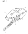
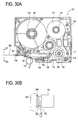
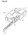
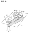
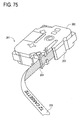
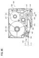
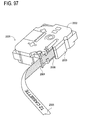
- Fig. 2 is a perspective view of the print cassette.
- a print cassette 1 of the first embodiment comprises an upper cassette case 2 and a lower cassette case 3.
- a print tape 5 is discharged from a tape discharging port 4.
- a reference numeral 6 indicates an ink ribbon. The width of the ink ribbon 6 is wider than that of the print tape 5.
- Fig. 3A is a plan view of the print cassette 1 from which the upper cassette case 2 (see Fig. 2 ) is removed.
- a tape spool 12 on which a second tape 13 is wound a film spool 14 on which a first tape 11 is wound, a ribbon supply spool 15 on which the ink ribbon 6 is wound, and a ribbon take-up spool 16 are provided on the lower cassette case 3 of the print cassette 1, being rotatable with cooperation of respective spool support members (not shown) formed on the upper cassette case 2 (see Fig. 2 ).
- a first base material (a handling auxiliary film) composed of a polyethylene terephthalate (hereinafter, referred to as "PET sheet") having a sheet thickness of approximately 70 ⁇ m and a to-be-printed medium (a thin laminated film) composed of an urethane sheet having a sheet thickness of approximately 10 ⁇ m are stacked and further, a first adhesive layer (a weak adhesive layer) is formed between the first base material and the to-be-printed medium by being coated with a first adhesive agent (a weak adhesive agent) in a thickness of approximately 25 ⁇ m. Then, the first tape 11 is wound on the film spool 14 with the to-be-printed medium side inside.
- a first adhesive layer a weak adhesive layer
- the first tape 11 wound in this way an inside surface (the first face side of the to-be-printed medium) wound on the film spool 14 will be a printing surface. Therefore, the first tape 11 wound on the film spool 14 is guided to an arm part 19 formed on the lower cassette case 3, via a guide pin 17 provided on the lower cassette case 3 in an upright position and a rotatable guide roller 18. The first tape 11 is further guided out of the arm part 19, being exposed outside a thermal head attachment space 20. After that, the first tape 11 is discharged from the tape cassette 1 through the tape discharging port 4, via a guide member 21 and a feed roller 22.
- the ink ribbon 6 is wound on the ribbon supply spool 15 with an ink-coated surface side inside.
- the ink ribbon 6 wound on the ribbon supply spool 15 in this way is exposed out of the arm part 19 outside the thermal head attachment space 20.
- the ink ribbon 6 is further guided while the ink-coated surface and the first face (side) of the to-be-printed medium are overlapped with each other. After that, the ink ribbon 6 is guided along an exterior of the guide member 21, thereby getting separated from the printing surface of the first tape 11. Finally, the ink ribbon 6 is taken up by the ribbon take-up spool 16.
- a thermal head H1 of the tape printer exists on the thermal head arrangement portion 20. Then, the first tape 11 and the ink ribbon 6 are nipped by the thermal head H1 and a platen roller P1 of the tape printer opposing the head H1.
- the second tape 13 has a second adhesive layer which is formed by being coated a second base material (a release sheet) having a sheet thickness of approximately 53 ⁇ m with a second adhesive agent of approximately 16 ⁇ m thick. Then, the second tape 13 is wound on the tape spool 12 with the second base material side outside. The second tape 13 wound in this way is guided by the feed roller 22 while the adhesive-coated surface of the second adhesive layer and the printing surface of the first tape 11 are overlapped with each other. As a result, the second tape 13 adheres to the first tape 11, and discharged outside the print cassette 1 through the tape discharging port 4.
- a second base material a release sheet
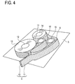
- Fig. 4 is a schematic view showing a process of the first tape 11, the second tape 13 and the ink ribbon 6 being guided on the lower cassette case 3 as described above.
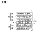
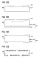
- Fig. 1 is a cross-sectional view of the print tape 5 taken along the line A1-A1 shown in Fig. 3A .
- the print tape 5 is composed of the first tape 11 and the second tape 13.
- a first base material 31 composed of a "PET sheet” having a sheet thickness of approximately 70 ⁇ m and a to-be-printed medium 33 composed of an urethane sheet having a sheet thickness of approximately 10 ⁇ m are stacked and further, a first adhesive layer 32 is formed between the first base material 31 and the second face (side) of the to-be-printed medium 33 by being coated with a first adhesive agent in a thickness of approximately 25 ⁇ m.
- the second tape 13 has a second adhesive layer 51 which is formed by being coated a second base material (a release sheet) 52 having a sheet thickness of approximately 53 ⁇ m with a second adhesive agent of approximately 16 ⁇ m thick.
- a printing surface 11A of the first tape 11 on which ink 41 is put and the second adhesive layer 51 are overlapped with each other, so that the second tape 13 adheres to the first tape 11 to compose the print tape 5.
- the print tape 5, from which the second base material 52 is removed so that the adhesive-coated surface of the second adhesive layer 51 is exposed can be stuck to an adherend.
- the first base material 31 is slowly removed, and then, as shown in Fig. 5 , the to-be-printed medium 33 can be stuck to an adherend 61 with the second adhesive layer 51 of the second tape 13, along with the ink 41 which is thermally transferred to the printing surface 11A thereof.
- the to-be-printed medium 33 and the second adhesive layer 51 appear to be in a floating state by the thickness of the ink 41, actually, the both adhered directly to each other because the thickness of the ink 41 is thin.
- the first adhesive agent making up the first adhesive layer 32 includes a copolymer as a main material, made by the copolymerization of monomers of any series such as an acrylic series, a rubber series and a silicone series.
- the first adhesive agent can be made with or without various kinds of additives (such as a crosslinking agent, a tackifier, a softner, a fixture and a pigment).
- the first adhesive agent having a low adhesive property is adopted since this is used for temporary adhesion and a part which will be removed eventually.
- the adhesive agent making up the second adhesive layer 51 include a copolymer as a main material, made by the copolymerization of monomers of any series such as an acrylic series, a rubber series and a silicone series.
- the adhesive agent can be made with or without various kinds of additives (such as a crosslinking agent, a tackifier, a softner, a fixture and a pigment).
- the adhesive agent having an adhesive property appropriate to the adherend 61 is adopted.
- the print cassette 1 is set in a cassette mount of a tape printer to produce the print tape 5.
- a cutter device (not shown) having a cutter to cut the print tape 5 discharged from the tape discharging port 4 of the print cassette 1.
- the structure of the print cassette 1 as explained with reference to Fig. 2 and other figures and the tape printer in which the print cassette 1 is installed to produce the print tape 5 have been publicly known, so the detailed explanation of the process for producing the print tape 5 with the print cassette 1 and the tape printer is omitted.
- the print tape 5 is discharged from the tape discharging port 4 of the print cassette 1 of the first embodiment, the print cassette 1 being set in a cassette mount of a tape printer.
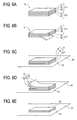
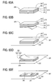
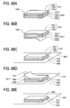
- the print tape 5 is cut with the cutter device of the tape printer to be a strip-formed tape composed of the first tape 1 (the first base material 31, the first adhesive layer 32 and the to-be-printed medium 33) and the second tape 13 (the second adhesive layer 51 and the second base material 52) as shown in Fig. 6A .
- the second base material 52 of the second tape 13 is removed, so that the second adhesive layer 51 of the second tape 13 is exposed. Further, the second adhesive layer 51 of the second tape 13 is stuck to the adherend 61 as shown in Fig. 6C .
- the first base material 31 is slowly removed from the adherend 61.
- the first adhesive layer 32 is also removed with the first base material 31, thus only the to-be-printed medium 33 can be left there.
- the to-be-printed medium 33 on which the ink 41 is thermally transferred is in a state of adhering to the adherend 61 with the second adhesive layer 51 of the second tape 13.
- the ink 41 has been thermally transferred from the ink ribbon 6 (see Fig. 3A and other figures) to the printing surface 11A (of the to-be-printed medium 33) of the first tape 11 (see Fig. 2 and other figures) with the tape printer.
- the print cassette 1 of the first embodiment is set in a cassette mount of a tape printer to produce the print tape 5 which is discharged from the tape printer.
- the print tape 5 discharged from the tape printer is cut by the cutter device of the tape printer, and then the second base material 52 is removed from the second tape 13 adhered to the first tape 11 (see Fig. 6B ).
- the exposed second adhesive layer 51 of the second tape 13 is stuck to the adherend 61 (see Fig. 6C ).
- the first base material 31 is slowly removed from the adherend 61 (see Fig. 6D ), so that the first adhesive layer 32 is removed with the first base material 31 and the to-be-printed medium 33 is left on the adherend 61 with the ink 41.
- Fig. 6D the first adhesive layer 32 is removed with the first base material 31 and the to-be-printed medium 33 is left on the adherend 61 with the ink 41.
- the to-be-printed medium 33 having the printing surface 11A on the back side thereof is stuck to the adherend 61 with the second adhesive layer 51 of the second tape 13.
- a "laminated tape” can be stuck to the adherend 61 (see Fig. 6E ).
- the to-be-printed medium 33 of the first tape 11 adheres to the second tape 13 with the second adhesive layer 51 thereof to be the print tape 5, which is discharged through the tape discharging port 4.
- the to-be-printed medium 33 can assure the feeding performance within the print cassette 1 of the first embodiment even though the to-be-printed medium 33 is thin.
- the first base material 31 is thicker than the to-be-printed medium 33, the feeding performance of the first tape 11 within the print cassette 1 of the first embodiment can be secured even however thin the to-be-printed medium 33 is.
- the second tape 13 is in a state of adhering to the first tape 11 when stuck to the adherend 61.
- the second tape 13 can thus keep the rigidity at least by the thickness of the first tape 11. Accordingly, however thin the to-be-printed medium 33 composing the "laminated tape” is, the "laminated tape” can easily be stuck to the adherend 61 as shown in Fig. 6 .
- the first base material 31 is thicker than the to-be-printed medium 33. Accordingly, however thin the to-be-printed medium 33 is, the first base material 31 can easily be removed.
- the first adhesive layer 32 which adheres the first base material 31 to the to-be-printed medium 33 is formed by being coated with the first adhesive agent between the first base material 31 and the to-be-printed medium 33 in a thickness of approximately 25 ⁇ m.
- the first adhesive agent may be filled to an entire range between the first base material 31 and the to-be-printed medium 33, the first adhesive agent may be coated in a predetermined pattern so that the first adhesive agent is dispersed uniformly.
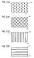
- Figs. 18A to 18D are views showing examples of coating patterns of the first adhesive agent to be coated for forming the first adhesive layer 32.
- Fig. 18A shows an example that the first adhesive layer 32 is formed in polka-dot pattern by being coated with the dot-like first adhesive agent to the first base material 31 intermittently (cyclically).
- Fig. 18B shows an example that the linear first adhesive agent is coated to the first base material 31 intermittently (cyclically) at an inclined angle so as to form the first adhesive layer 32 into a grid pattern.
- Fig. 18C shows an example that the linear first adhesive agent is coated to the first base material 31 intermittently (cyclically) in the width direction so as to form the first adhesive layer 32 in a striped pattern.
- Fig. 18D shows an example that the linear first adhesive agent is coated to the first base material 31 intermittently (cyclically) in the longitudinal direction so as to form the first adhesive layer 32 into a striped pattern.
- the print tape 5 can thus keep the rigidity at least by the thickness of the first base material 31. Accordingly, the feeding performance within the print cassette 1 of the first embodiment can be secured.
- the first adhesive agent which forms the first adhesive layer 32 is dispersed uniformly in a predetermined pattern as shown in Figs.
- the first adhesive agent which is to form the first adhesive layer 32 is not pushed out from between the to-be-printed medium 33 and the first base material 31 easily.
- the feeding performance of the to-be-printed medium 33 within the print cassette 1 of the first embodiment is stabilized further.
- the print tape 5 that is, the to-be-printed medium 33
- the first adhesive agent which forms the first adhesive layer 32 is dispersed uniformly in a predetermined pattern as shown in Figs.
- the total thickness of the to-be-printed medium 33 and the second tape 13 is as thin as approximately 30 ⁇ m. Therefore, the outline of the to-be-printed medium 33 is hardly visible if the to-be-printed medium 33 is transparent and colorless, so that the ink 41 (printed contents) on the to-be-printed medium 33 can be prominent. Additionally, the total weight of the to-be-printed medium 33 and the second tape 13 is so light as to reduce adverse effect on rotational balance of the adherend 61 as a body of rotation such as a CD and a DVD.
- the to-be-printed medium 33 when stuck to the curved surface of the adherend 61, the to-be-printed medium 33 is as thin as 10 ⁇ m, thus the to-be-printed medium 33 can be prevented from being gradually unstuck. This effect can be achieved even if the thickness of the to-be-printed medium 33 is as large as 30 ⁇ m.
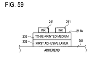
- the printing surface 11A on which the ink 41 is thermally transferred exists on the back side of the to-be-printed medium 33, that is, the printing surface 11A is laminated by the to-be-printed medium 33, thereby presenting abrasion resistance which is a feature of the "laminated tape".
- the disclosure may be embodied in other specific forms without departing from the essential characteristics thereof.
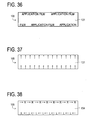
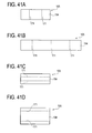
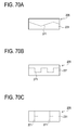
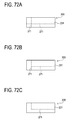
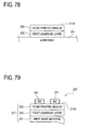
- the first base material 31 may have a width wider than that of the to-be-printed medium 33 as shown in a plan view of Fig. 7 .
- the first base material 31 may have a width narrower than that of the to-be-printed medium 33, as shown in a plan view of Fig. 8 .
- the first base material 31 and the to-be-printed medium 33 are different in width, which makes it easy to distinguish the first base material 31 and to unstuck the first base material 31. This is the same if the width of the second base material 52 of the second tape 13 is wider (not shown).
- the presence of the first base material 31 can be emphasized with prints such as characters and patterns (in Fig. 9 , for example, characters of "APPLICATION FILM") representing the first base material 31 preliminarily printed on the first base material 31 itself, thereby facilitating the work to unstick the first base material 31.
- characters and patterns in Fig. 9 , for example, characters of "APPLICATION FILM"
- the print tape 5 is allowed to be stuck readily to the adherend 61 (see Fig. 6 and other figures).
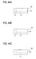
- the second base material 52 of the second tape 13 comprising the print tape 5 may preliminarily be provided with a half cut 71. This configuration can facilitate the work to remove the second base material 52 of the second tape 13.
- the first base material 31 may preliminarily be provided with a half cut 81 in advance, which allows the first base material 31 to be unstuck easily.
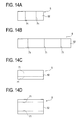
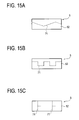
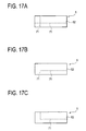
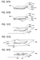
- Figs. 14A to 17C show various configurations of half cuts 71 implemented in the second base material 52 preliminarily.
- Figs. 14A and 14B show an example that a plurality of half cuts 71 are implemented in the width direction of the second base material 52
- Figs. 14C and 14D show an example that a plurality of half cuts 71 are implemented in the longitudinal direction of the second base material 52.
- Figs. 15A, 15B, and 15C show an example that a linear half cut 71 is implemented in the second base material 52.
- Figs. 16A, 16B, and 16C show an example that a curved half cut 71 is implemented in the second base material 52.
- Figs. 17A, 17B, and 17C show an example that the half cuts 71 in the width direction and in the longitudinal direction are implemented by combination in the second base material 52.
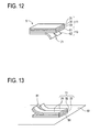
- the second base material 52 adhered to the to-be-printed medium 33 with the second adhesive layer 51 (see Fig. 6A ). Then, when part of the second base material 52 is removed from the to-be-printed medium 33 along the half cut 71 in order to stick the to-be-printed medium 33 to the adherend 61 (see Figs. 6B and 12 ), part of the second adhesive layer 51 is exposed, so that part of the to-be-printed medium 33 can be stuck to the adherend 61 with the part of the second adhesive layer 51 (see Figs. 6C and 12 ).
- the left portion of the second base material 52 still adhered to the to-be-printed medium 33, so that the to-be-printed medium 33 can thus keep the rigidity by the stiffness of the left portion of the second base material 52. Consequently, however thin the to-be-printed medium 33 is, the work of sticking part of the to-be-printed medium 33 to the adherend 61 securely without generation of wrinkles can be carried out.
- the left portion of the second adhesive layer 51 is exposed when the left portion of the second base material 52 is removed from the to-be-printed medium 33, the left portion of the to-be-printed medium 33 can be stuck to the adherend 61 with the left portion of the second adhesive layer 51.
- the to-be-printed medium 33 can thus keep the tension by part of the to-be-printed medium 33 stuck to the adherend 61. Consequently, however thin the to-be-printed medium 33 is, the work of sticking the left portion of the to-be-printed medium 33 to the adherend 61 securely without generation of wrinkles can be carried out.
- the to-be-printed medium 33 can be stuck to the adherend 61 step by step. This facilitates the work of securely sticking the to-be-printed medium 33 to the adherend 61 without generation of wrinkles.
- the first base material 31 adhered to the to-be-printed medium 33 see Figs. 6B and 12 ), so that the to-be-printed medium 33 can thus keep the rigidity by the stiffness of the first base material 31. Consequently, however thin the to-be-printed medium 33 is, the work of sticking the to-be-printed medium 33 to the adherend 61 securely without generation of wrinkles can be carried out.
- the first base material 31 can be removed easily from the to-be-printed medium 33 by the half cut 81 (see Fig. 13 ).
- the various configurations of the half cuts 71 implemented in the second base material 52 preliminarily shown in Figs. 14 to 17 may be adopted as configurations of the half cuts 81 to be implemented in the first base material 31 preliminarily.
- the first base material 31 may be a transparent and colorless tape or a colored and transparent tape.
- the transparent and colorless first base material 31 allows the ink 41 thermally transferred to the printing surface 11A (see Fig. 1 and other figures) of the first tape 11 to be visually identified therethrough, so that the top and bottom of the print tape 5 can be distinguished easily, thereby facilitating the work to stick the print tape 5 to the adherend 61.
- the colored and transparent first base material 31 allows not only the ink 41 thermally transferred to the printing surface 11A (see Fig. 1 and other figures) of the first tape 11 but also the presence of the first base material 31 itself to be identified visually. This can facilitate the work to stick the print tape 5 to the adherend 61 and the work to unstick the first base material 31.
- the first base material 31 is opaque, the ink 41 thermally transferred to the printing surface 11A (of the to-be-printed medium 33) of the first tape 11 (see Fig. 1 and other figures) cannot be recognized visually.
- the print tape 5 which is produced in a tape printer by using the print cassette 1 of the first embodiment, as described above, the first base material 31 adhered to the to-be-printed medium 33 with the first adhesive layer 32.
- the first base material 31 is opaque, as described above, the ink 41 thermally transferred to the printing surface 11A (of the to-be-printed medium 33) of the first tape 11 (see Fig. 1 and other figures) cannot be recognized visually, the first base material 31 has the hiding performance.
- the to-be-printed medium 33 cannot be recognized visually via the first base material 31, so that the ink 41 (the printing content) of the to-be-printed medium 33 can be hidden. Consequently, the security effect to the printing content of the to-be-printed medium 33 is exerted.
- Fig. 10 is a drawing showing an example that the mark (arrows) indicating the up-down direction of the printing surface 11A (of the to-be-printed medium 33) of the first tape 11 (see Fig. 1 and other figures) is provided on the first base material 31 preliminarily.
- Fig. 11 is a drawing showing an example that the mark (" ⁇ R", “L ⁇ ”) indicating the right-left direction of the printing surface 11A (of the to-be-printed medium 33) of the first tape 11 (see Fig. 1 and other figures) is provided on the second base material 52 preliminarily.
- the direction of the mark " ⁇ R” indicates rightward.
- the direction of the mark "L ⁇ ” indicates leftward. Further, these marks may be provided on the first base material 31 preliminarily.
- the mark indicating the up-down direction or the right-left direction of the printing surface 11A (of the to-be-printed medium 33) of the first tape 11 is provided on the first base material 31 or the second base material 52 preliminarily.
- the printing surface 11A (of the to-be-printed medium 33) of the first tape 11 is printed by the thermal head H1 of the tape printer designed to exist in the thermal head arrangement portion 20 and the platen P1 opposing the thermal head H1 as shown in Fig. 3A .
- the printing surface 11A (of the to-be-printed medium 33) of the first tape 11 opposes the thermal head H1 of the tape printer via the ink face of the ink ribbon 6 (see Figs. 2 and 3A).
- Fig. 3B shows a view taken along the line F1-F1 of Fig. 3A in this state.
- the to-be-printed medium 33 of the first tape 11 is covered with the ink ribbon 6, so that the to-be-printed medium 33 is hidden from the thermal head H1 of the tape printer.
- the width of the ink ribbon 6 is wider than the width of the first tape 11.
- the print tape 5 produced by a tape printer using the print cassette 1 of the first embodiment is of thermal transfer type which is printed by the thermal head H1 of the tape printer and the ink ribbon 6.
- a thermosensitive type which does not require the ink ribbon 6 can obtain the above-described various effects (except an effect of blocking a bad influence by heat at the time of print by the ink ribbon 6 easily).
- a thermosensitive type print tape 5 is produced by a tape printer will be described by applying this to the print cassette 1 of the first embodiment in order to mainly indicate a difference from the thermal transfer type print tape 5.
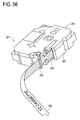
- Fig. 20 is a perspective view of the print cassette.
- the print cassette 1 of the first embodiment comprises an upper cassette case 2 and a lower cassette case 3.
- the print tape 5 is discharged from the tape discharge port 4.
- the ink ribbon 6 shown in Fig. 1 does not exist here.
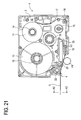
- Fig. 21 is a plan view of the print cassette 1 from which the upper cassette case 2 (see Fig. 20 ) is removed.
- a tape spool 12 on which a second tape 13 is wound, a film spool 14 on which a first tape 11 is wound, a ribbon supply spool 15 and a ribbon take-up spool 16 are provided on the lower cassette case 3 of the print cassette 1, being rotatable with cooperation of respective spool support members (not shown) formed on the upper cassette case 2 (see Fig. 47 ).
- No ink ribbon 6 exists on the ribbon supply spool 15 and the ribbon winding spool 16.
- a first base material (a handling auxiliary film) composed of a "PET sheet” having a sheet thickness of approximately 70 ⁇ m and a to-be-printed medium (a thin laminated film) composed of an urethane sheet having a sheet thickness of approximately 10 ⁇ m are stacked and further, a first adhesive layer (a weak adhesive layer) is formed between the first base material and the to-be-printed medium by being coated with a first adhesive agent (a weak adhesive agent) in a thickness of approximately 25 ⁇ m. Then, the first tape 11 is wound on the film spool 14 with its to-be-printed medium side inside.
- a first adhesive layer a weak adhesive layer
- the first tape 11 wound in this way an inside surface (the first face side of the to-be-printed medium) wound on the film spool 14 will be a printing surface. Therefore, the first tape 11 wound on the film spool 14 is guided to an arm part 19 formed on the lower cassette case 3, via a guide pin 17 provided on the lower cassette case 3 in an upright position and a rotatable guide roller 18. The first tape 11 is further guided out of the arm part 19, being exposed outside a thermal head attachment space 20. After that, the first tape 11 is discharged from the tape cassette 1 through the tape discharging port 4, via a guide member 21 and a feed roller 22.
- a thermal head H1 of the tape printer exists on the thermal head arrangement portion 20. Then, the first tape 11 is nipped by the thermal head H1 and a platen roller P1 of the tape printer opposing the head H1.
- the second tape 13 has a second adhesive layer which is formed by being coated a second base material (a release sheet) having a sheet thickness of approximately 53 ⁇ m with a second adhesive agent of approximately 16 ⁇ m thick. Then, the second tape 13 is wound on the tape spool 12 with the second base material side outside. The second tape 13 wound in this way is guided by the feed roller 22 while the adhesive-coated surface of the second adhesive layer and the printing surface of the first tape 11 are overlapped with each other. As a result, the second tape 13 adheres to the first tape 11, and discharged outside the print cassette 1 through the tape discharging port 4.
- a second base material a release sheet
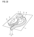
- Fig. 22 is a schematic view showing a process of the first tape 11 and the second tape 13 being guided on the lower cassette case 3 as described above.
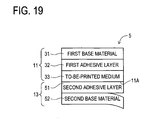
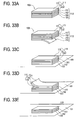
- Fig. 19 is a cross-sectional view of the print tape 5 taken along the line A2-A2 shown in Fig. 21 .
- the print tape 5 is composed of the first tape 11 and the second tape 13.
- a first base material 31 composed of a "PET sheet” having a sheet thickness of approximately 70 ⁇ m and a to-be-printed medium 33 composed of an urethane sheet having a sheet thickness of approximately 10 ⁇ m are stacked and further, a first adhesive layer 32 is formed between the first base material 31 and the second face (side) of the to-be-printed medium 33 by being coated with a first adhesive agent in a thickness of approximately 25 ⁇ m.
- the first face (side) of the to-be-printed medium 33 is coated with a thermosensitive coloring agent.
- the printing surface 11A of the first tape 11 is formed thereof.
- thermosensitive coloring agent coated to the printing surface 11A (of the to-be-printed medium 33) of the first tape 11 is discolored by the thermal head H1 of the tape printer designed to exist in the thermal head arrangement portion 20 so as to print.
- the second tape 13 has a second adhesive layer 51 which is formed by being coated a second base material (a release sheet) 52 having a sheet thickness of approximately 53 ⁇ m with a second adhesive agent of approximately 16 ⁇ m thick.
- a printing surface 11A of the first tape 11 and the second adhesive layer 51 are overlapped with each other, so that the second tape 13 adheres to the first tape 11 to compose the print tape 5.
- the print tape 5, from which the second base material 52 is removed so that the adhesive-coated surface of the second adhesive layer 51 is exposed can be stuck to an adherend.
- the first base material 31 is slowly removed, and then, as shown in Fig. 23 , the to-be-printed medium 33 can be stuck to an adherend 61 with the second adhesive layer 51 of the second tape 13.
- the first tape 11 is constituted by adhering the first base material 31 and the to-be-printed medium 33 with the first adhesive layer 32, the first tape 11 may be constituted of only the to-be-printed medium 33.
- Fig. 24 is a view showing a section of the print tape 5 produced using the first tape 11 constituted of only the to-be-printed medium 33.
- the print tape 5 is constituted of the first tape 11 and the second tape 13 as shown in Fig. 24 .
- the first tape 11 is constituted only of the to-be-printed medium 33 composed of an urethane sheet having a sheet thickness of approximately 10 ⁇ m.
- the second tape 13 has the second adhesive layer 51 which is formed by being coated the second base material 52 having a sheet thickness of approximately 53 ⁇ m with a second adhesive agent of approximately 16 ⁇ m thick.
- the printing surface 11A of the first tape 11 on which ink 41 is put and the second adhesive layer 51 are overlapped with each other, so that the second tape 13 adheres to the first tape 11 to compose the print tape 5.
- the to-be-printed medium 33 and the second adhesive layer 51 appear to be in a floating state by the thickness of the ink 41, actually, the both adhered directly to each other because the thickness of the ink 41 is thin.
- the print tape 5 is discharged from the tape discharging port 4 of the print cassette 1 of the first embodiment, the print cassette 1 being set in a cassette mount of a tape printer.
- the print tape 5 is cut with the cutter device of the tape printer to be a strip-formed tape composed of the first tape 11 (the to-be-printed medium 33) and the second tape 13 (the second adhesive layer 51 and the second base material 52) as shown in Fig. 25A .
- the second base material 52 of the second tape 13 is removed, so that the second adhesive layer 51 of the second tape 13 is exposed. Further, the second adhesive layer 51 of the second tape 13 is stuck to the adherend 61 as shown in Fig. 25C .
- the second base material 52 of the second tape 13 comprising the print tape 5 may preliminarily be provided with a half cut 71.
- This configuration can facilitate the work to remove the second base material 52 of the second tape 13.
- the half cut 71 to be implemented preliminarily in the second base material 52 may be of various configurations showing in Figs. 14 to 17 as described above and even in this case, the above-described effect which the half cut 71 exerts can be obtained.
- the print tape 5 produced using the first tape 11 constituted only of the to-be-printed medium 33 is not limited to the thermal transfer type but may be of the thermosensitive type.
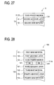
- Fig. 27 is a view showing the section of such a thermosensitive type print tape 5.
- the thermosensitive type print tape 5 is constituted of a first tape 11 and a second tape 13.
- the first tape 11 is constituted only of a to-be-printed medium 33 composed of an urethane sheet having a sheet thickness of approximately 10 ⁇ m.
- the first face (side) of the to-be-printed medium 33 is coated with a thermosensitive coloring agent.
- a printing surface 11A of the first tape 11 is constituted thereof.
- the second tape 13 has a second adhesive layer 51 which is formed by being coated a second base material (a release sheet) 52 having a sheet thickness of approximately 53 ⁇ m with a second adhesive agent of approximately 16 ⁇ m thick.
- the printing surface 11A of the first tape 11 and the second adhesive layer 51 are overlapped with each other, so that the second tape 13 adheres to the first tape 11 to compose the thermosensitive type print tape 5.
- the print tape 5 produced by a tape printer using the print cassette 1 can obtain the above-described various effects (excluding effects exerted within the print cassette 1).
- the width of the ink ribbon 6 is wider than the width of the print tape 5, the width of the ink ribbon 6 may be equal to the width of the print tape 5.
- the thickness of the to-be-printed medium 33 is 2.5 ⁇ m to 30 ⁇ m.
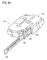
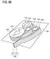
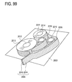
- Fig. 29 is a perspective view of the print cassette.
- a print cassette 101 of the second embodiment comprises an upper cassette case 102 and a lower cassette case 103.
- a print tape 105 is discharged from a tape discharging port 104.
- a reference numeral 106 indicates an ink ribbon. The width of the ink ribbon 106 is wider than that of the print tape 105.
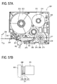
- Fig. 30A is a plan view of the print cassette 101 from which the upper cassette case 102 (see Fig. 29 ) is removed.
- a tape spool 112 on which a third tape 113 is wound a film spool 114 on which a first tape 111 is wound, a ribbon supply spool 115 on which the ink ribbon 106 is wound, and a ribbon take-up spool 116 are provided on the lower cassette case 103 of the print cassette 101, being rotatable with cooperation of respective spool support members (not shown) formed on the upper cassette case 102 (see Fig. 29 ).
- a first base material (a handling auxiliary film) composed of a "PET sheet” having a sheet thickness of approximately 70 ⁇ m and a to-be-printed medium (a thin laminated film) composed of an urethane sheet having a sheet thickness of approximately 10 ⁇ m are stacked and further, a first adhesive layer (a weak adhesive layer) is formed between the first base material and the to-be-printed medium by being coated with a first adhesive agent (a weak adhesive agent) in a thickness of approximately 25 ⁇ m. Then, the first tape 111 is wound on the film spool 114 with its to-be-printed medium side inside.
- a first adhesive layer a weak adhesive layer
- the first tape 111 wound in this way an inside surface (the first face side of the to-be-printed medium) wound on the film spool 114 will be a printing surface. Therefore, the first tape 111 wound on the film spool 114 is guided to an arm part 119 formed on the lower cassette case 103, via a guide pin 117 provided on the lower cassette case 103 in an upright position and a rotatable guide roller 118. The first tape 111 is further guided out of the arm part 119, being exposed outside a thermal head attachment space 120. After that, the first tape 111 is discharged from the tape cassette 101 through the tape discharging port 104, via a guide member 121 and a feed roller 122.
- the ink ribbon 106 is wound on the ribbon supply spool 115 with an ink-coated surface side inside.
- the ink ribbon 106 wound on the ribbon supply spool 115 in this way is exposed out of the arm part 119 outside the thermal head attachment space 120.
- the ink ribbon 106 is further guided while the ink-coated surface and the first face (side) of the to-be-printed medium are overlapped with each other. After that, the ink ribbon 106 is guided along an exterior of the guide member 121, thereby getting separated from the printing surface of the first tape 111. Finally, the ink ribbon 106 is taken up by the ribbon take-up spool 116.
- a thermal head H2 of the tape printer exists on the thermal head arrangement portion 120. Then, the first tape 111 and the ink ribbon 106 are nipped by the thermal head H2 and a platen roller P2 of the tape printer opposing the head H2.
- the third tape 113 has a third adhesive layer which is formed by being coated the first face side of a third base material (a base film) composed of a "PET sheet" having a sheet thickness of approximately 12 ⁇ m with a third adhesive agent of approximately 20 ⁇ m thick.
- the second face side of the third base material is coated with a fourth adhesive agent so as to form a fourth adhesive layer having a thickness of approximately 16 ⁇ m.
- a fourth base material (a release sheet) having a thickness of approximately 53 ⁇ m adhered to the fourth adhesive layer.
- the third tape 113 is wound on the tape spool 112 with the fourth base material side outside.
- the third tape 113 wound in this way is guided by the feed roller 122 while the adhesive-coated surface of the third adhesive layer and the printing surface of the first tape 111 are overlapped with each other. As a result, the third tape 113 adheres to the first tape 111, and discharged outside the print cassette 101 through the tape discharging port 104.
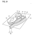
- Fig. 31 is a schematic view showing a process of the first tape 111, the third tape 113 and the ink ribbon 106 being guided on the lower cassette case 103 as described above.
- Fig. 28 is a cross-sectional view of the print tape 105 taken along the B1-B1 shown in Fig. 30A .
- the print tape 105 is composed of the first tape 111 and the third tape 113.
- a first base material 131 composed of a "PET sheet” having a sheet thickness of approximately 70 ⁇ m and a to-be-printed medium 133 composed of an urethane sheet having a sheet thickness of approximately 10 ⁇ m are stacked and further, a first adhesive layer 132 is formed between the first base material 131 and the second face (side) of the to-be-printed medium 133 by being coated with a first adhesive agent in a thickness of approximately 25 ⁇ m.
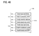
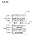
- the third tape 113 is configured such that the first face side of the third base material 152 composed of a "PET sheet" having a sheet thickness of approximately 12 ⁇ m is coated with a third adhesive agent to form a third adhesive layer 151 in a thickness of approximately 20 ⁇ m and the second face side of the third base material 152 is coated with a fourth adhesive agent to form a fourth adhesive layer 153 in a thickness of approximately 16 ⁇ m. Further, a fourth base material 154 having a thickness of approximately 53 ⁇ m adhered to the fourth adhesive layer 153. A printing surface 111A of the first tape 111 on which ink 141 is put and the third adhesive layer 151 are overlapped with each other, so that the third tape 113 adheres to the first tape 111 to compose the print tape 105.
- the print tape 105 from which the fourth base material 154 is removed so that the adhesive-coated surface of the fourth adhesive layer 153 is exposed, can be stuck to an adherend.
- the first base material 131 is slowly removed, and then, as shown in Fig. 32 , the to-be-printed medium 133 can be stuck to an adherend 161 with the third adhesive layer 151, the third base material 152 and the fourth adhesive layer 153 of the third tape 113, along with the ink 141 which is thermally transferred to the printing surface 111A thereof.
- the to-be-printed medium 133 and the third adhesive layer 151 appear to be in a floating state by the thickness of the ink 141, actually, the both adhered directly to each other because the thickness of the ink 141 is thin.
- the first adhesive agent making up the first adhesive layer 132 includes a copolymer as a main material, made by the copolymerization of monomers of any series such as an acrylic series, a rubber series and a silicone series.
- the first adhesive agent can be made with or without various kinds of additives (such as a crosslinking agent, a tackifier, a softner, a fixture and a pigment).
- the first adhesive agent having a low adhesive property is adopted since this is used for temporary adhesion and a part which will be removed eventually.
- the adhesive agent making up the third adhesive layer 151 and the fourth adhesive layer 153 include a copolymer as a main material, made by the copolymerization of monomers of any series such as an acrylic series, a rubber series and a silicone series.
- the adhesive agent can be made with or without various kinds of additives (such as a crosslinking agent, a tackifier, a softner, a fixture and a pigment).
- the adhesive agent having an adhesive property appropriate to the adherend 161 is adopted.
- the print cassette 101 is set in a cassette mount of a tape printer to produce the print tape 105.
- a cutter device (not shown) having a cutter to cut the print tape 105 discharged from the tape discharging port 104 of the print cassette 101.
- the structure of the print cassette 101 as explained with reference to Fig. 29 and other figures and the tape printer in which the print cassette 101 is installed to produce the print tape 105 have been publicly known, so the detailed explanation of the process for producing the print tape 105 with the print cassette 101 and the tape printer is omitted.
- the print tape 105 is discharged from the tape discharging port 104 of the print cassette 101 of the second embodiment, the print cassette 101 being set in a cassette mount of a tape printer.
- the print tape 105 is cut with the cutter device of the tape printer to be a strip-formed tape composed of the first tape 111 (the first base material 131, the first adhesive layer 132 and the to-be-printed medium 133) and the third tape 113 (the third adhesive layer 151, the third base material 152, the fourth adhesive layer 153 and the fourth base material 154) as shown in Fig. 33A .
- the first tape 111 the first base material 131, the first adhesive layer 132 and the to-be-printed medium 133
- the third tape 113 the third adhesive layer 151, the third base material 152, the fourth adhesive layer 153 and the fourth base material 154
- the fourth base material 154 of the third tape 113 is removed, so that the fourth adhesive layer 153 of the third tape 113 is exposed. Further, the fourth adhesive layer 153 of the third tape 113 is stuck to the adherend 161 as shown in Fig. 33C .
- the first base material 131 is slowly removed from the adherend 161.
- the first adhesive layer 132 is also removed with the first base material 131, thus only the to-be-printed medium 133 can be left there.
- the to-be-printed medium 133 on which the ink 141 is thermally transferred is in a state of adhering to the adherend 161 with the third adhesive layer 151, third base material 152 and fourth adhesive layer 153 of the third tape 113.
- the ink 141 has been thermally transferred from the ink ribbon 106 (see Fig. 30A and other figures) to the printing surface 111A (of the to-be-printed medium 133) of the first tape 111 (see Fig. 28 and other figures) with the tape printer.
- the print cassette 101 of the second embodiment is set in a cassette mount of a tape printer to produce the print tape 105 which is discharged from the tape printer.
- the print tape 105 discharged from the tape printer is cut by the cutter device of the tape printer, and then the fourth base material 154 is removed from the third tape 113 adhered to the first tape 111 (see Fig. 33B ).
- the exposed fourth adhesive layer 153 of the third tape 113 is stuck to the adherend 161 (see Fig. 33C ). Further, the first base material 131 is slowly removed from the adherend 161 (see Fig.
- the to-be-printed medium 133 can assure the feeding performance within the print cassette 101 of the second embodiment even though the to-be-printed medium 133 is thin.
- the feeding performance of the first tape 111 within the print cassette 101 of the second embodiment can be secured even however thin the to-be-printed medium 133 is.
- the third tape 113 is in a state of adhering to the first tape 111 when stuck to the adherend 161.
- the third tape 113 can thus keep the rigidity at least by the thickness of the first tape 111. Accordingly, however thin the to-be-printed medium 133 composing the "laminated tape” is, the "laminated tape” can easily be stuck to the adherend 161 as shown in Fig. 33 .
- the first base material 131 is thicker than the to-be-printed medium 133. Accordingly, however thin the to-be-printed medium 133 is, the first base material 131 can easily be removed.
- the first adhesive layer 132 which adheres the first base material 131 to the to-be-printed medium 133 is formed by being coated with the first adhesive agent between the first base material 131 and the to-be-printed medium 133 in a thickness of approximately 25 ⁇ m.
- the first adhesive agent may be filled to an entire range between the first base material 131 and the to-be-printed medium 133, the first adhesive agent may be coated in a predetermined pattern so that the first adhesive agent is dispersed uniformly.
- Figs. 45A to 45D are views showing examples of coating patterns of the first adhesive agent to be coated for forming the first adhesive layer 132.
- Fig. 45A shows an example that the first adhesive layer 132 is formed in polka-dot pattern by being coated with the dot-like first adhesive agent to the first base material 131 intermittently (cyclically).
- Fig. 45B shows an example that the linear first adhesive agent is coated to the first base material 131 intermittently (cyclically) at an inclined angle so as to form the first adhesive layer 132 into a grid pattern.
- Fig. 45C shows an example that the linear first adhesive agent is coated to the first base material 131 intermittently (cyclically) in the width direction so as to form the first adhesive layer 132 in a striped pattern.
- Fig. 45D shows an example that the linear first adhesive agent is coated to the first base material 131 intermittently (cyclically) in the longitudinal direction so as to form the first adhesive layer 132 into a striped pattern.
- the print tape 105 can thus keep the rigidity at least by the thickness of the first base material 131. Accordingly, the feeding performance within the print cassette 101 of the second embodiment can be secured.
- the first adhesive agent which forms the first adhesive layer 132 is dispersed uniformly in a predetermined pattern as shown in Figs.
- the first adhesive agent which is to form the first adhesive layer 132 is not pushed out from between the to-be-printed medium 133 and the first base material 131 easily.
- the feeding performance of the to-be-printed medium 133 within the print cassette 101 of the second embodiment is stabilized further.
- the print tape 105 that is, the to-be-printed medium 133
- the first adhesive agent which forms the first adhesive layer 132 is dispersed uniformly in a predetermined pattern as shown in Figs.
- the total thickness of the to-be-printed medium 133 and the third tape 113 is as thin as approximately 58 ⁇ m. Therefore, the outline of the to-be-printed medium 133 is hardly visible if the to-be-printed medium 133 is transparent and colorless, so that the ink 141 (printed contents) on the to-be-printed medium 133 can be prominent. Additionally, the total weight of the to-be-printed medium 133 and the third tape 113 is so light as to reduce adverse effect on rotational balance of the adherend 161 as a body of rotation such as a CD and a DVD.
- the to-be-printed medium 133 when stuck to the curved surface of the adherend 161, the to-be-printed medium 133 is as thin as 10 ⁇ m, thus the to-be-printed medium 133 can be prevented from being gradually unstuck. This effect can be achieved even if the thickness of the to-be-printed medium 133 is as large as 30 ⁇ m.
- the printing surface 111A on which the ink 141 is thermally transferred exists on the back side of the to-be-printed medium 133, that is, the printing surface 111A is laminated by the to-be-printed medium 133, thereby presenting abrasion resistance which is a feature of the "laminated tape".
- the disclosure may be embodied in other specific forms without departing from the essential characteristics thereof.
- the first base material 131 may have a width wider than that of the to-be-printed medium 133 as shown in a plan view of Fig. 34 .
- the first base material 131 may have a width narrower than that of the to-be-printed medium 133, as shown in a plan view of Fig. 35 .
- the first base material 131 and the to-be-printed medium 133 are different in width, which makes it easy to distinguish the first base material 131 and to unstuck the first base material 131. This is the same if the width of the forth base material 154 of the third tape 113 is wider (not shown).
- the presence of the first base material 131 can be emphasized with prints such as characters and patterns (in Fig. 36 , for example, characters of "APPLICATION FILM") representing the first base material 131 preliminarily printed on the first base material 131 itself, thereby facilitating the work to unstick the first base material 131.
- characters and patterns in Fig. 36 , for example, characters of "APPLICATION FILM"
- the print tape 105 is allowed to be stuck readily to the adherend 161 (see Fig. 33 and other figures).
- the fourth base material 154 of the third tape 113 comprising the print tape 105 may preliminarily be provided with a half cut 171. This configuration can facilitate the work to remove the fourth base material 154 of the third tape 113.
- the first base material 131 may preliminarily be provided with a half cut 181 in advance, which allows the first base material 131 to be unstuck easily.
- Figs. 41A to 44C show various configurations of half cuts 171 implemented in the fourth base material 154 preliminarily.
- Figs. 41A and 41B show an example that a plurality of half cuts 171 are implemented in the width direction of the fourth base material 154
- Figs. 41C and 41D show an example that a plurality of half cuts 171 are implemented in the longitudinal direction of the fourth base material 154.
- Figs. 42A, 42B, and 42C show an example that a linear half cut 171 is implemented in the fourth base material 154.
- Figs. 43A, 43B, and 43C show an example that a curved half cut 171 is implemented in the fourth base material 154.
- Figs. 44A, 44B, and 44C show an example that the half cuts 171 in the width direction and in the longitudinal direction are implemented by combination in the fourth base material 154.
- the print tape 105 which is produced in a tape printer by using the print cassette 101 of the second embodiment, as described above, the third base material 152 adhered to the to-be-printed medium 133 with the third adhesive layer 151, so that the to-be-printed medium 133 and the third base material 152 are integrally formed (see Fig. 33A ). Then, when part of the fourth base material 154 adhered to the third base material 152 with the fourth adhesive layer 153 is removed from the third base material 152 along the half cut 171 in order to stick the to-be-printed medium 133 to the adherend 161 (see Figs.
- part of the fourth adhesive layer 153 is exposed, so that part of the to-be-printed medium 133 integrated with the third base material 152 can be stuck to the adherend 161 with the part of the fourth adhesive layer 153 (see Figs. 33C and 39 ).
- the left portion of the fourth base material 154 still adhered to the to-be-printed medium 133 via the third base material 152, so that the to-be-printed medium 133 can thus keep the rigidity by the stiffness of the left portion of the fourth base material 154. Consequently, however thin the to-be-printed medium 133 is, the work of sticking part of the to-be-printed medium 133 to the adherend 161 securely without generation of wrinkles can be carried out.
- the left portion of the fourth adhesive layer 153 is exposed when the left portion of the fourth base material 154 is removed from the third base material 152 integrated with the to-be-printed medium 133
- the left portion of the to-be-printed medium 133 integrated with the third base material 152 can be stuck to the adherend 161 with the left portion of the fourth adhesive layer 154.
- the to-be-printed medium 133 can thus keep the tension by part of the to-be-printed medium 133 stuck to the adherend 161. Consequently, however thin the to-be-printed medium 133 is, the work of sticking the left portion of the to-be-printed medium 133 to the adherend 161 securely without generation of wrinkles can be carried out.
- the to-be-printed medium 133 can be stuck to the adherend 161 step by step. This facilitates the work of securely sticking the to-be-printed medium 133 to the adherend 161 without generation of wrinkles.
- the first base material 131 adhered to the to-be-printed medium 133 see Figs. 33B and 39 ), so that the to-be-printed medium 133 can thus keep the rigidity by the stiffness of the first base material 131. Consequently, however thin the to-be-printed medium 133 is, the work of sticking the to-be-printed medium 133 to the adherend 161 securely without generation of wrinkles can be carried out.
- the first base material 131 can be removed easily from the to-be-printed medium 133 by the half cut 181 (see Fig. 40 ).
- the first base material 131 may be a transparent and colorless tape or a colored and transparent tape.
- the transparent and colorless first base material 131 this allows the ink 141 thermally transferred to the printing surface 111A (see Fig. 28 and other figures) of the first tape 111 to be visually identified therethrough, so that the top and bottom of the print tape 105 can be distinguished easily, thereby facilitating the work to stick the print tape 105 to the adherend 161.
- the colored and transparent first base material 131 allows not only the ink 141 thermally transferred to the printing surface 111A (see Fig. 28 and other figures) of the first tape 111 but also the presence of the first base material 131 itself to be identified visually. This can facilitate the work to stick the print tape 105 to the adherend 161 and the work to unstick the first base material 131.
- the ink 141 thermally transferred to the printing surface 111A (of the to-be-printed medium 133) of the first tape 111 (see Fig. 28 and other figures) cannot be recognized visually.
- the print tape 105 which is produced in a tape printer by using the print cassette 101 of the second embodiment, as described above, the first base material 131 adhered to the to-be-printed medium 133 with the first adhesive layer 132.
- the ink 141 thermally transferred to the printing surface 111A (of the to-be-printed medium 133) of the first tape 111 (see Fig.
- the first base material 131 has the hiding performance. Accordingly, the to-be-printed medium 133 cannot be recognized visually via the first base material 131, so that the ink 141 (the printing content) of the to-be-printed medium 133 can be hidden. Consequently, the security effect to the printing content of the to-be-printed medium 133 is exerted.
- a mark indicating the up-down direction or right-left direction of the printing surface 111A (of the to-be-printed medium 133) of the first tape 111 is provided on the first base material 131 or the fourth base material 154 preliminarily, it is convenient.
- Fig. 37 is a drawing showing an example that the mark (arrows) indicating the up-down direction of the printing surface 111A (of the to-be-printed medium 133) of the first tape 111 (see Fig. 28 and other figures) is provided on the first base material 131 preliminarily.
- Fig. 38 is a drawing showing an example that the mark (" ⁇ R", “L ⁇ ”) indicating the right-left direction of the printing surface 111A (of the to-be-printed medium 133) of the first tape 111 (see Fig. 28 and other figures) is provided on the fourth base material 154 preliminarily.
- the direction of the mark " ⁇ R” indicates rightward.
- the direction of the mark "L ⁇ " indicates leftward. Further, these marks may be provided on the first base material 131 preliminarily.
- the mark indicating the up-down direction or the right-left direction of the printing surface 111A (of the to-be-printed medium 133) of the first tape 111 is provided on the first base material 131 or the fourth base material 154 preliminarily.
- the up-down direction or the right-left direction of the to-be-printed medium 133 is never mistaken as long as this mark is used as a clue, so that the print tape 105 (to-be-printed medium 133) can be stuck to the adherend 161.
- the printing surface 111A (of the to-be-printed medium 133) of the first tape 111 is printed by the thermal head H2 of the tape printer designed to exist in the thermal head arrangement portion 120 and the platen P2 opposing the thermal head H2 as shown in Fig. 30A .
- the printing surface 111A (of the to-be-printed medium 133) of the first tape 111 opposes the thermal head H2 of the tape printer via the ink face of the ink ribbon 106 (see Figs. 29 and 30A).
- FIG. 30B shows a view taken along the line F2-F2 of Fig. 30A in this state.
- the to-be-printed medium 133 of the first tape 111 is covered with the ink ribbon 106, so that the to-be-printed medium 133 is hidden from the thermal head H2 of the tape printer.
- the width of the ink ribbon 106 is wider than the width of the first tape 111.
- the print tape 105 produced by a tape printer using the print cassette 101 of the second embodiment is of thermal transfer type which is printed by the thermal head H2 of the tape printer and the ink ribbon 106.
- a thermosensitive type which does not require the ink ribbon 106 can obtain the above-described various effects (except an effect of blocking a bad influence by heat at the time of print by the ink ribbon 106 easily).
- a thermosensitive type print tape 105 is produced by the tape printer will be described by applying this to the print cassette 101 of the second embodiment in order to mainly indicate a difference from the thermal transfer type print tape 105.
- Fig. 47 is a perspective view of the print cassette.
- the print cassette 101 of the second embodiment comprises an upper cassette case 102 and a lower cassette case 103.
- the print tape 105 is discharged from the tape discharge port 104.
- the ink ribbon 106 shown in Fig. 29 does not exist here.
- Fig. 48 is a plan view of the print cassette 101 from which the upper cassette case 102 (see Fig. 47 ) is removed.
- a tape spool 112 on which a third tape 113 is wound a film spool 114 on which a first tape 111 is wound, a ribbon supply spool 115 and a ribbon take-up spool 116 are provided on the lower cassette case 103 of the print cassette 101, being rotatable with cooperation of respective spool support members (not shown) formed on the upper cassette case 102 (see Fig. 47 ).
- No ink ribbon 106 exists on the ribbon supply spool 115 and the ribbon winding spool 116.
- a first base material (a handling auxiliary film) composed of a "PET sheet” having a sheet thickness of approximately 70 ⁇ m and a to-be-printed medium (a thin laminated film) composed of an urethane sheet having a sheet thickness of approximately 10 ⁇ m are stacked and further, a first adhesive layer (a weak adhesive layer) is formed between the first base material and the to-be-printed medium by being coated with a first adhesive agent (a weak adhesive agent) in a thickness of approximately 25 ⁇ m. Then, the first tape 111 is wound on the film spool 114 with its to-be-printed medium side inside.
- a first adhesive layer a weak adhesive layer
- the first tape 111 wound in this way an inside surface (the first face side of the to-be-printed medium) wound on the film spool 114 will be a printing surface. Therefore, the first tape 111 wound on the film spool 114 is guided to an arm part 119 formed on the lower cassette case 103, via a guide pin 117 provided on the lower cassette case 103 in an upright position and a rotatable guide roller 118. The first tape 111 is further guided out of the arm part 119, being exposed outside a thermal head attachment space 120. After that, the first tape 111 is discharged from the tape cassette 101 through the tape discharging port 104, via a guide member 121 and a feed roller 122.
- a thermal head H2 of the tape printer exists on the thermal head arrangement portion 120. Then, the first tape 111 is nipped by the thermal head H2 and a platen roller P2 of the tape printer opposing the head H2.
- the third tape 113 has a third adhesive layer which is formed by being coated the first face side of a third base material (a base film) composed of a "PET sheet" having a sheet thickness of approximately 12 ⁇ m with a third adhesive agent of approximately 20 ⁇ m thick.
- the second face side of the third base material is coated with a fourth adhesive agent so as to form a fourth adhesive layer having a thickness of approximately 16 ⁇ m.
- a fourth base material (a release sheet) having a thickness of approximately 53 ⁇ m adhered to the fourth adhesive layer.
- the third tape 113 is wound on the tape spool 112 with the fourth base material side outside.
- the third tape 113 wound in this way is guided by the feed roller 122 while the adhesive-coated surface of the third adhesive layer and the printing surface of the first tape 111 are overlapped with each other. As a result, the third tape 113 adheres to the first tape 111, and discharged outside the print cassette 101 through the tape discharging port 104.
- Fig. 49 is a schematic view showing a process of the first tape 111 and the third tape 113 being guided on the lower cassette case 103 as described above.
- Fig. 46 is a cross-sectional view of the print tape 105 taken along the line B2-B2 shown in Fig. 48 .
- the print tape 105 is composed of the first tape 111 and the third tape 113.
- a first base material 131 composed of a "PET sheet” having a sheet thickness of approximately 70 ⁇ m and a to-be-printed medium 133 composed of an urethane sheet having a sheet thickness of approximately 10 ⁇ m are stacked and further, a first adhesive layer 132 is formed between the first base material 131 and the second face (side) of the to-be-printed medium 133 by being coated with a first adhesive agent in a thickness of approximately 25 ⁇ m.
- the first face (side) of the to-be-printed medium 133 is coated with a thermosensitive coloring agent.
- a printing surface 111A of the first tape 111 is formed thereof.
- thermosensitive coloring agent coated to the printing surface 111A (of the to-be-printed medium 133) of the first tape 111 is discolored by the thermal head H2 of the tape printer designed to exist in the thermal head arrangement portion 120 so as to print.
- the third tape 113 is configured such that the first face side of the third base material 152 composed of a "PET sheet" having a sheet thickness of approximately 12 ⁇ m is coated with a third adhesive agent to form a third adhesive layer 151 in a thickness of approximately 20 ⁇ m and the second face side of the third base material 152 is coated with a fourth adhesive agent to form a fourth adhesive layer 153 in a thickness of approximately 16 ⁇ m. Further, a fourth base material 154 having a thickness of approximately 53 ⁇ m adhered to the fourth adhesive layer 153.
- the printing surface 111A of the first tape 111 and the third adhesive layer 151 are overlapped with each other, so that the third tape 113 adheres to the first tape 111 to compose the print tape 105.
- the print tape 105 from which the fourth base material 154 is removed so that the adhesive-coated surface of the fourth adhesive layer 153 is exposed, can be stuck to an adherend.
- the first base material 131 is slowly removed, and then, as shown in Fig. 50 , the to-be-printed medium 133 can be stuck to an adherend 161 with the third adhesive layer 151, the third base material 152 and the fourth adhesive layer 153 of the third tape 113.
- the first tape 111 is constituted by sticking the first base material 131 and the to-be-printed medium 133 with the first adhesive layer 132, the first tape 111 may be constituted of only the to-be-printed medium 133.
- Fig. 51 is a view showing a section of the print tape 105 produced using the first tape 111 constituted of only the to-be-printed medium 133.
- the print tape 105 is constituted of the first tape 111 and the third tape 113 as shown in Fig. 51 .
- the first tape 111 is constituted only of the to-be-printed medium 133 composed of an urethane sheet having a sheet thickness of approximately 10 ⁇ m.
- the third tape 113 is configured such that the first face side of the third base material 152 composed of a "PET sheet" having a sheet thickness of approximately 12 ⁇ m is coated with a third adhesive agent to form the third adhesive layer 151 in a thickness of approximately 20 ⁇ m and the second face side of the third base material 152 is coated with a fourth adhesive agent to form the fourth adhesive layer 153 in a thickness of approximately 16 ⁇ m.
- the fourth base material 154 having a thickness of approximately 53 ⁇ m adhered to the fourth adhesive layer 153.
- the printing surface 111A of the first tape 111 on which ink 141 is put and the third adhesive layer 151 are overlapped with each other, so that the third tape 113 adheres to the first tape 111 to compose the print tape 105.
- the to-be-printed medium 133 and the third adhesive layer 151 appear to be in a floating state by the thickness of the ink 141, actually, the both adhered directly to each other because the thickness of the ink 141 is thin.
- the print tape 105 is discharged from the tape discharging port 104 of the print cassette 101 of the second embodiment, the print cassette 101 being set in a cassette mount of a tape printer.
- the print tape 105 is cut with the cutter device of the tape printer to be a strip-formed tape composed of the first tape 111 (the to-be-printed medium 133) and the third tape 113 (the third adhesive layer 151, the third base material 152, the fourth adhesive layer 153 and the fourth base material 154) as shown in Fig. 52A .
- the first tape 111 the to-be-printed medium 133
- the third tape 113 the third adhesive layer 151, the third base material 152, the fourth adhesive layer 153 and the fourth base material 154
- the fourth base material 154 of the third tape 113 is removed, so that the fourth adhesive layer 153 of the third tape 113 is exposed. Further, the fourth adhesive layer 153 of the third tape 113 is stuck to the adherend 161 as shown in Fig. 52C .
- the fourth base material 154 of the third tape 113 comprising the print tape 105 may preliminarily be provided with a half cut 171.
- This configuration can facilitate the work to remove the fourth base material 154 of the third tape 113.
- the half cut 171 to be implemented preliminarily in the fourth base material 154 may be of various configurations showing in Figs. 41 to 44 as described above and even in this case, the above-described effect which the half cut 171 exerts can be obtained.
- the print tape 105 produced using the first tape 111 constituted only of the to-be-printed medium 133 is not limited to the thermal transfer type but may be of the thermosensitive type.
- Fig. 54 is a view showing the section of such a thermosensitive type print tape 105.
- thermosensitive type print tape 105 is constituted of a first tape 111 and a third tape 113.
- the first tape 111 is constituted only of a to-be-printed medium 133 composed of an urethane sheet having a sheet thickness of approximately 10 ⁇ m.
- the first face (side) of the to-be-printed medium 133 is coated with a thermosensitive coloring agent.
- a printing surface 111A of the first tape 111 is constituted thereof.
- the third tape 113 is configured such that the first face side of a third base material 152 composed of a "PET sheet" having a sheet thickness of approximately 12 ⁇ m is coated with a third adhesive agent to form a third adhesive layer 151 in a thickness of approximately 20 ⁇ m and the second face side of the third base material 152 is coated with a fourth adhesive agent to form a fourth adhesive layer 153 in a thickness of approximately 16 ⁇ m. Further, a fourth base material 154 having a thickness of approximately 53 ⁇ m adhered to the fourth adhesive layer 153.
- the printing surface 111A of the first tape 111 and the third adhesive layer 151 are overlapped with each other, so that the third tape 113 adheres to the first tape 111 to compose the thermosensitive type print tape 105.
- the print tape 105 produced by a tape printer using the print cassette 101 even a sheet-like print tape (including a wide tape-like one) which cannot be produced using the tape printer in which the print cassette 101 is set can obtain the above-described various effects (excluding effects exerted within the print cassette 101).
- the width of the ink ribbon 106 is wider than the width of the print tape 105, the width of the ink ribbon 106 may be equal to the width of the print tape 105.
- the thickness of the to-be-printed medium 133 is 2.5 ⁇ m to 30 ⁇ m.
- Fig. 56 is a perspective view of a print cassette.
- a print cassette 201 of the third embodiment comprises an upper cassette case 202 and a lower cassette case 203.
- a print tape 205 is discharged from a tape discharging port 204.
- a reference numeral 206 indicates an ink ribbon. The width of the ink ribbon 206 is wider than the width of the print tape 205.
- Fig. 57A is a plan view of the print cassette 201 from which the upper cassette case 202 (see Fig. 56 ) is removed.
- a tape spool 212 on which a second tape 213 is wound a film spool 214 on which a first tape 211 is wound, a ribbon supply spool 215 on which the ink ribbon 206 is wound, and a ribbon take-up spool 216 are provided on the lower cassette case 203 of the print cassette 201, being rotatable with cooperation of respective spool support members (not shown) formed on the upper cassette case 202 (see Fig. 56 ).
- the first tape 211 has a first adhesive layer which is formed by being coated the second face side of a to-be-printed medium (a thin base film) composed of an urethane sheet having a sheet thickness of approximately 10 ⁇ m to 15 ⁇ m with an adhesive agent of approximately 16 ⁇ m thick. Further, a release sheet adhered to the first adhesive layer. Then, an inside surface (the first face side of the to-be-printed medium) wound on the film spool 214 will be a printing surface. Therefore, the first tape 211 wound on the film spool 214 is guided to an arm part 219 formed on the lower cassette case 203, via a guide pin 217 provided on the lower cassette case 203 in an upright position and a rotatable guide roller 218.
- a to-be-printed medium a thin base film
- the first tape 211 is further guided out of the arm part 219, being exposed outside a thermal head attachment space 220. After that, the first tape 211 is discharged from the tape cassette 201 through the tape discharging port 204, via a guide member 221 and a feed roller 222.
- the ink ribbon 206 is wound on the ribbon supply spool 215 with an ink-coated surface side inside.
- the ink ribbon 206 wound on the ribbon supply spool 215 in this way is exposed out of the arm part 219 outside the thermal head attachment space 220.
- the ink ribbon 206 is further guided while the ink-coated surface and the printing surface of the first tape 211 are overlapped with each other. After that, the ink ribbon 206 is guided along an exterior of the guide member 221, thereby getting separated from the printing surface of the first tape 211. Finally, the ink ribbon 206 is taken up by the ribbon take-up spool 216.
- a thermal head H3 of the tape printer exists on the thermal head arrangement portion 220. Then, the first tape 211 and the ink ribbon 206 are nipped by the thermal head H3 and a platen roller P3 of the tape printer opposing the head H3.
- a second tape 213 has a second adhesive layer (a weak adhesive layer) which is formed by being coated with the first face side of a second base material (a handling auxiliary film) composed of a "PET sheet" with a second adhesive agent (a weak adhesive agent) of approximately 25 ⁇ m thick.
- the second tape 213 is wound on the tape spool 212 with the second base material side outside.
- the second tape 213 wound in this way is guided by the feed roller 222 while the adhesive-coated surface of the second adhesive layer and the printing surface of the first tape 211 are overlapped with each other.
- the second tape 213 adheres to the first tape 211, and discharged outside the print cassette 201 through the tape discharging port 204.
- the printing surface of the first tape 211 is an adhesion object surface of the second adhesive layer of the second tape 213.
- Fig. 58 is a schematic view showing a process of the second tape 213, the first tape 211 and the ink ribbon 206 being guided on the lower cassette case 203 as described above.
- Fig. 55 is a cross-sectional view of the print tape 205 taken along the line C1-C1 shown in Fig. 57A .
- the print tape 205 is composed of the first tape 211 and the second tape 213.
- the application tape 2013 has a weak adhesive layer 2052 which is formed by being coated the first face side of a handling auxiliary film 2051 composed of a "PET sheet" with a weak adhesive agent of approximately 25 ⁇ m thick.
- the thin film tape 2011 has an adhesive layer 2033 which is formed by being coated the second face side of a thin base film 2031 composed of an urethane sheet having a sheet thickness of approximately 10 ⁇ m to 15 ⁇ m with an adhesive agent of approximately 16 ⁇ m thick. Further, a release sheet 2034 adhered to the adhesive layer 2033. Then, a printing surface 211A (of the to-be-printed medium 233) of the first tape 211 on which ink 241 is put and the second adhesive layer 251 are overlapped with each other, so that the first tape 211 adheres to the second tape 213 to compose the print tape 205. Accordingly, the printing surface 211A (of the to-be-printed medium 233) of the first tape 211 is an adhesion object surface of the second adhesive layer 251 of the second tape 213.
- the print tape 205 from which the first base material 231 is removed so that the adhesive-coated surface of the first adhesive layer 232 is exposed, can be stuck to an adherend.
- the second tape 213 is slowly removed, and then, as shown in Fig. 59 , the to-be-printed medium 233 can adhere to an adherend 261 with the first adhesive layer 232, along with the ink 241 which is thermally transferred to the printing surface 211A thereof.
- the to-be-printed medium 233 and the second adhesive layer 251 appear to be in a floating state by the thickness of the ink 241, actually, the both adhered directly to each other because the thickness of the ink 241 is thin.
- the second adhesive agent making up the second adhesive layer 251 includes a copolymer as a main material, made by the copolymerization of monomers of any series such as an acrylic series, a rubber series and a silicone series.
- the second adhesive agent can be made with or without various kinds of additives (such as a crosslinking agent, a tackifier, a softner, a fixture and a pigment).
- the second adhesive agent having a low adhesive property is adopted since this is used for temporary adhesion and a part which will be removed eventually.
- the adhesive agent making up the first adhesive layer 232 includes a copolymer as a main material, made by the copolymerization of monomers of any series such as an acrylic series, a rubber series and a silicone series.
- the adhesive agent can be made with or without various kinds of additives (such as a crosslinking agent, a tackifier, a softner, a fixture and a pigment).
- the adhesive agent having an adhesive property appropriate to the adherend 261 is adopted.
- the print cassette 201 is set in a cassette mount of a tape printer to produce the print tape 205.
- a cutter device (not shown) having a cutter to cut the print tape 205 discharged from the tape discharging port 204 of the print cassette 201.
- the structure of the print cassette 201 as explained with reference to Fig. 56 and other figures and the tape printer in which the print cassette 201 is installed to produce the print tape 205 have been publicly known, so the detailed explanation of the process for producing the print tape 205 with the print cassette 201 and the tape printer is omitted.
- the print tape 205 is discharged from the tape discharging port 204 of the print cassette 201 of the present embodiment, the print cassette 201 being set in a cassette mount of a tape printer.
- the print tape 205 is cut with the cutter device of the tape printer (not shown) to be a strip-formed tape composed of the first tape 211 (the first base material 231, the first adhesive layer 232 and the to-be-printed medium 233) and the second tape 213 (the second adhesive layer 251 and the second base material 252) as shown in Fig. 60A .
- the cutter device of the tape printer not shown
- the first base material 231 of the first tape 211 is removed, so that the first adhesive layer 232 of the first tape 211 is exposed. Further, the first adhesive layer 232 of the first tape 211 is stuck to the adherend 261 as shown in Fig. 60C .
- the second base material 252 is slowly removed from the adherend 261.
- the second adhesive layer 251 is also removed with the second base material 252, thus only the second tape 213 can be removed therefrom.
- the to-be-printed medium 233 on which the ink 241 is thermally transferred is in a state of adhering to the adherend 261 with the first adhesive layer 232.
- the ink 241 has been thermally transferred from the ink ribbon 206 (see Fig. 57A and other figures) to the printing surface 211A (of the to-be-printed medium 233) of the first tape 211 (see Fig. 55 and other figures) with the tape printer.
- the print cassette 201 of the third embodiment is set in a cassette mount of a tape printer to produce the print tape 205 which is discharged from the tape printer.
- the print tape 205 discharged from the tape printer is cut by the cutter device of the tape printer, and then the first base material 231 is removed from the first tape 211 adhered to the second tape 213 (see Fig. 60B ).
- the exposed first adhesive layer 232 of the first tape 211 is stuck to the adherend 261 (see Fig. 60C ).
- the second tape 213 is slowly removed from the adherend 261 (see Fig. 60D ), so that the second tape 213 is removed and the to-be-printed medium 233 is left on the adherend 261 with the ink 241.
- Fig. 60D As shown in Fig.
- the to-be-printed medium 233 having the printing surface 211A, on which the ink 241 thermally transferred, exposed on the first face side can be stuck to the adherend 261 with the first adhesive layer 232.
- a "non-laminated tape" can be stuck to the adherend 261 (see Fig. 60E ).
- the second tape 213 is in a state of adhering to the first tape 211 when stuck to the adherend 261.
- the second tape 213 can thus keep the rigidity at least by the thickness of the second tape 213. Accordingly, however thin the to-be-printed medium 233 composing the "non-laminated tape” is, the "non-laminated tape” can easily be stuck to the adherend 261 as shown in Fig. 60 .
- the second tape 213 should be thin and stretch.
- the thickness of the second tape 213 is 30 ⁇ m to 50 ⁇ m, in the point of view which is the keeping of the easiness of the work of sticking.
- the to-be-printed medium 233 is thicker than the second base material 252. Accordingly, however thin the to-be-printed medium 233 is, the second base material 252 can easily be removed.
- the second adhesive layer 251 which adheres the second base material 252 to the to-be-printed medium 233 is formed by being coated with the first adhesive agent to the first side of the second base material 252 in a thickness of approximately 25 ⁇ m.
- the second adhesive agent may be filled to an entire range of the second base material 252, the second adhesive agent may be coated in a predetermined pattern so that the first adhesive agent is dispersed uniformly.
- Figs. 73A to 73D are views showing examples of coating patterns of the second adhesive agent to be coated for forming the second adhesive layer 251.
- Fig. 73A shows an example that the second adhesive layer 251 is formed in polka-dot pattern by being coated with the dot-like second adhesive agent to the second base material 252 intermittently (cyclically).
- Fig. 73B shows an example that the linear second adhesive agent is coated to the second base material 252 intermittently (cyclically) at an inclined angle so as to form the second adhesive layer 251 into a grid pattern.
- Fig. 73C shows an example that the linear second adhesive agent is coated to the second base material 252 intermittently (cyclically) in the width direction so as to form the second adhesive layer 251 in a striped pattern.
- Fig. 73D shows an example that the linear second adhesive agent is coated to the second base material 252 intermittently (cyclically) in the longitudinal direction so as to form the second adhesive layer 251 into a striped pattern.
- the print tape 205 can thus keep the rigidity at least by the thickness of the second base material 252. Accordingly, the feeding performance within the print cassette 201 of the third embodiment can be secured.
- the second adhesive agent which forms the second adhesive layer 251 is dispersed uniformly in a predetermined pattern as shown in Figs.
- the second adhesive agent which is to form the second adhesive layer 251 is not pushed out from between the to-be-printed medium 233 and the second base material 252 easily.
- the feeding performance of the to-be-printed medium 233 within the print cassette 201 of the third embodiment is stabilized further.
- the total thickness of the to-be-printed medium 233 and the first adhesive layer 232 is as thin as approximately 26 ⁇ m to 31 ⁇ m. Therefore, the outline of the to-be-printed medium 233 is hardly visible if it is transparent and colorless, so that the ink 241 (printed contents) on the to-be-printed medium 233 can be prominent. Additionally, the total weight of the to-be-printed medium 233 and the first adhesive layer 232 is so light as to reduce adverse effect on rotational balance of the adherend 261 as a body of rotation such as a CD and a DVD.
- the to-be-printed medium 233 when stuck to the curved surface of the adherend 261, the to-be-printed medium 233 is as thin as 10 ⁇ m to 15 ⁇ m, thus the to-be-printed medium 233 can be prevented from being gradually unstuck. This effect can be achieved even if the thickness of the to-be-printed medium 233 is as large as 30 ⁇ m.
- the second tape 213 may have a width wider than that of the first tape 211 as shown in a plan view of Fig. 61 .
- the second tape 213 may have a width narrower than that of the first base material 231 of the first tape 211, as shown in a plan view of Fig. 63 .
- the to-be-printed medium 233 and first adhesive layer 232 of the first tape 211 may have a width narrower than that of the second tape 213.
- the second tape 213 and the first base material 231 of the first tape 211 are different in width, which makes it easy to distinguish the second tape 213 and the first base material 231 of the first tape 211, and to unstick the second tape 2133 and the first base material 231 of the first tape 211.
- the first base material 231 of the first tape 211 comprising the print tape 205 may preliminarily be provided with a half cut 271. This configuration can facilitate the work to remove the first base material 231 of the first tape 211.
- the second tape 213 may preliminarily be provided with a half cut 281 in advance, which allows the second tape 213 to be unstuck easily.
- Figs. 69A to 72C show various configurations of half cuts 271 implemented in the first base material 231 preliminarily.
- Figs. 69A and 69B show an example that a plurality of half cuts 271 are implemented in the width direction of the first base material 231
- Figs. 69C and 69D show an example that a plurality of half cuts 271 are implemented in the longitudinal direction of the first base material 231.
- Figs. 70A, 70B, and 70C show an example that a linear half cut 271 is implemented in the first base material 231.
- Figs. 71A, 71B, and 71C show an example that a curved half cut 271 is implemented in the first base material 231.
- Figs. 72A, 72B, and 72C show an example that the half cuts 271 in the width direction and in the longitudinal direction are implemented by combination in the first base material 231.
- the print tape 205 which is produced in a tape printer by using the print cassette 201 of the third embodiment, as described above, the first base material 231 adhered to the to-be-printed medium 233 with the first adhesive layer 232, so that the to-be-printed medium 233 and the first base material 231 are integrally formed (see Fig. 60A ). Then, when part of the first base material 231 is removed from the to-be-printed medium 233 along the half cut 271 in order to stick the to-be-printed medium 233 to the adherend 261 (see Figs. 60B and 67 ), part of the first adhesive layer 232 is exposed, so that part of the to-be-printed medium 233 can be stuck to the adherend 261 with the part of the first adhesive layer 232 (see Figs. 60C and 67 ).
- the left portion of the first base material 231 still adhered to the to-be-printed medium 233, so that the to-be-printed medium 233 can thus keep the rigidity by the stiffness of the left portion of the first base material 231. Consequently, however thin the to-be-printed medium 233 is, the work of sticking part of the to-be-printed medium 233 to the adherend 261 securely without generation of wrinkles can be carried out.
- the left portion of the first adhesive layer 232 is exposed when the left portion of the first base material 231 is removed from the to-be-printed medium 233, the left portion of the to-be-printed medium 233 can be stuck to the adherend 261 with the left portion of the first adhesive layer 232.
- the to-be-printed medium 233 can thus keep the tension by part of the to-be-printed medium 233 stuck to the adherend 261. Consequently, however thin the to-be-printed medium 233 is, the work of sticking the left portion of the to-be-printed medium 233 to the adherend 261 securely without generation of wrinkles can be carried out.
- the to-be-printed medium 233 can be stuck to the adherend 261 step by step. This facilitates the work of securely sticking the to-be-printed medium 233 to the adherend 261 without generation of wrinkles.
- the second base material 252 adhered to the to-be-printed medium 233 see Figs. 60B and 67 ), so that the to-be-printed medium 233 can thus keep the rigidity by the stiffness of the second base material 252. Consequently, however thin the to-be-printed medium 233 is, the work of sticking the to-be-printed medium 233 to the adherend 261 securely without generation of wrinkles can be carried out.
- the second base material 252 can be removed easily from the to-be-printed medium 233 by the half cut 281 (see Fig. 68 ).
- the second tape 213 may be a transparent and colorless tape or a colored and transparent tape.
- this allows the ink 241 thermally transferred to the printing surface 211A (see Fig. 55 and other figures) of the first tape 211 to be visually identified therethrough, so that the top and bottom of the print tape 205 can be distinguished easily, thereby facilitating the work to stick the print tape 205 to the adherend 261.
- the colored and transparent second tape 213 allows not only the ink 241 thermally transferred to the printing surface 211A (see Fig 55 and other figures) of the first tape 211 but also the presence of the second tape 213 itself to be identified visually. This can facilitate the work to stick the print tape 205 to the adherend 261 and the work to unstick the second tape 213.
- the second base material 252 is opaque, the ink 241 thermally transferred to the printing surface 211A (of the to-be-printed medium 233) of the first tape 211 (see Fig. 55 and other figures) cannot be recognized visually.
- the print tape 205 which is produced in a tape printer by using the print cassette 201 of the third embodiment, as described above, the second base material 252 adhered to the to-be-printed medium 233 with the second adhesive layer 251.
- the ink 241 thermally transferred to the printing surface 211A (of the to-be-printed medium 233) of the first tape 211 (see Fig.
- the second base material 252 has the hiding performance. Accordingly, the to-be-printed medium 233 cannot be recognized visually via the second base material 252, so that the ink 241 (the printing content) of the to-be-printed medium 233 can be hidden. Consequently, the security effect to the printing content of the to-be-printed medium 233 is exerted.
- Fig. 65 is a drawing showing an example that the mark (arrows) indicating the up-down direction of the printing surface 211A (of the to-be-printed medium 233) of the first tape 211 (see Fig. 55 and other figures) is provided on the second base material 252 preliminarily.
- Fig. 66 is a drawing showing an example that the mark (" ⁇ R", “L ⁇ ”) indicating the right-left direction of the printing surface 211A (of the to-be-printed medium 233) of the first tape 211 (see Fig. 55 and other figures) is provided on the first base material 231 preliminarily.
- the direction of the mark " ⁇ R” indicates rightward.
- the direction of the mark "L ⁇ " indicates leftward. Further, these marks may be provided on the second base material 252 preliminarily.
- the mark indicating the up-down direction or the right-left direction of the printing surface 211A (of the to-be-printed medium 233) of the first tape 211 is provided on the first base material 231 or the second base material 252 preliminarily.
- the up-down direction or the right-left direction of the to-be-printed medium 233 is never mistaken as long as this mark is used as a clue, so that the print tape 205 (to-be-printed medium 233) can be stuck to the adherend 261.
- the printing surface 211A (of the to-be-printed medium 233) of the first tape 211 is printed by the thermal head H3 of the tape printer designed to exist in the thermal head arrangement portion 220 and the platen P3 opposing the thermal head H3 as shown in Fig. 57A .
- the printing surface 211A (of the to-be-printed medium 233) of the first tape 211 opposes the thermal head H3 of the tape printer via the ink face of the ink ribbon 206 (see Figs. 56 and 57A).
- FIG. 57B shows a view taken along the line F3-F3 of Fig. 57A in this state.
- the to-be-printed medium 233 of the first tape 211 is covered with the ink ribbon 206, so that the to-be-printed medium 233 is hidden from the thermal head H3 of the tape printer.
- the width of the ink ribbon 206 is wider than the width of the first tape 211.
- the print tape 205 produced by a tape printer using the print cassette 201 of the third embodiment is of thermal transfer type which is printed by the thermal head H3 of the tape printer and the ink ribbon 206.
- a thermosensitive type which does not require the ink ribbon 206 can obtain the above-described various effects (except an effect of blocking a bad influence by heat at the time of print by the ink ribbon 206 easily).
- a thermosensitive type print tape 205 is produced by the tape printer will be described by applying this to the print cassette 201 of the third embodiment in order to mainly indicate a difference from the thermal transfer type print tape 205.
- Fig. 75 is a perspective view of the print cassette.
- the print cassette 201 of the third embodiment comprises an upper cassette case 202 and a lower cassette case 203.
- the print tape 205 is discharged from the tape discharge port 204.
- the ink ribbon 206 shown in Fig. 56 does not exist here.
- Fig. 76 is a plan view of the print cassette 201 from which the upper cassette case 202 (see Fig. 75 ) is removed.
- a tape spool 212 on which a second tape 213 is wound a film spool 214 on which a first tape 211 is wound, a ribbon supply spool 215 and a ribbon take-up spool 216 are provided on the lower cassette case 203 of the print cassette 201, being rotatable with cooperation of respective spool support members (not shown) formed on the upper cassette case 202 (see Fig. 75 ).
- No ink ribbon 206 exists on the ribbon supply spool 215 and the ribbon winding spool 216.
- the first tape 211 has a first adhesive layer which is formed by being coated the second face side of a to-be-printed medium composed of an urethane sheet having a sheet thickness of approximately 10 ⁇ m to 15 ⁇ m with an adhesive agent of approximately 16 ⁇ m thick. Further, a release sheet adhered to the first adhesive layer. Then, an inside surface (the first face side of the to-be-printed medium) wound on the film spool 214 will be a printing surface. Therefore, the first tape 211 wound on the film spool 214 is guided to an arm part 219 formed on the lower cassette case 203, via a guide pin 217 provided on the lower cassette case 203 in an upright position and a rotatable guide roller 218.
- the first tape 211 is further guided out of the arm part 219, being exposed outside a thermal head attachment space 220. After that, the first tape 211 is discharged from the tape discharging port 204, via a guide member 221 and a feed roller 222.
- a thermal head H3 of the tape printer exists on the thermal head arrangement portion 220. Then, the first tape 211 is nipped by the thermal head H3 and a platen roller P3 of the tape printer opposing the head H3.
- the second tape 213 has a second adhesive layer (a weak adhesive layer) which is formed by being coated the first face side of a second base material (a handling auxiliary film) composed of a "PET sheet" with a second adhesive agent (a weak adhesive agent) of approximately 25 ⁇ m thick.
- the second tape 213 is wound on the tape spool 212 with the second base material side outside.
- the second tape 213 wound in this way is guided by the feed roller 222 while the adhesive-coated surface of the second adhesive layer and the printing surface of the first tape 211 are overlapped with each other.
- the second tape 213 adheres to the first tape 211, and discharged outside the print cassette 201 through the tape discharging port 204.
- the printing surface of the first tape 211 is an adhesion object surface of the second adhesive layer of the second tape 213.
- Fig. 77 is a schematic view showing a process of the first tape 211 and the second tape 213 being guided on the lower cassette case 203 as described above.
- Fig. 74 is a cross-sectional view of the print tape 205 taken along the line C2-C2 shown in Fig. 76 .
- the print tape 205 is composed of the first tape 211 and the second tape 213.
- the first tape 211 has a first adhesive layer 232 which is formed by being coated the second face side of a to-be-printed medium 233 composed of an urethane sheet having a sheet thickness of approximately 10 ⁇ m to 15 ⁇ m with an adhesive agent of approximately 16 ⁇ m thick. Further, a first base material 231 adhered to the first adhesive layer 233.
- the first face (side) of the to-be-printed medium 233 is coated with a thermosensitive coloring agent.
- the printing surface 211A of the first tape 211 is formed thereof.
- thermosensitive coloring agent coated to the printing surface 211A (of the to-be-printed medium 233) of the first tape 211 is discolored by the thermal head H3 of the tape printer designed to exist in the thermal head arrangement portion 220 so as to print.
- the second tape 213 has a second adhesive layer 251 which is formed by being coated the first face side of a second base material 252 composed of a "PET sheet" with a second adhesive agent of approximately 25 ⁇ m thick.
- a printing surface 211A (of the to-be-printed medium 233) of the first tape 211 and the second adhesive layer 251 are overlapped with each other, so that the first tape 211 adheres to the second tape 213 to compose the print tape 205.
- the printing surface 211A (of the to-be-printed medium 233) of the first tape 211 is an adhesion object surface of the second adhesive layer 251 of the second tape 213.
- the print tape 205 from which the first base material 231 is removed so that the adhesive-coated surface of the first adhesive layer 232 is exposed, can be stuck to an adherend.
- the second base material 252 is slowly removed, and then, as shown in Fig. 78 , the to-be-printed medium 233 can be stuck to an adherend 261 with the first adhesive layer 232.
- the print tape 205 is composed of the first tape 211 and the second tape 213, the print tape 205 may be constituted of only the first tape 211.
- Fig. 79 is a view showing a section of the print tape 205 produced using only the first tape 211.
- the print tape 205 is constituted only of the first tape 211 as shown in Fig. 79 .
- the first tape 211 has the first adhesive layer 232 which is formed by being coated the second face side of the to-be-printed medium 233 composed of an urethane sheet having a sheet thickness of approximately 10 ⁇ m to 15 ⁇ m with an adhesive agent of approximately 16 ⁇ m thick. Further, the first base material 231 adhered to the first adhesive layer 233.
- the ink 241 is thermally transferred to the printing surface 211A of the first tape 211 to compose the print tape 205.
- the print tape 205 is discharged from the tape discharging port 204 of the print cassette 201 of the third embodiment, the print cassette 201 being set in a cassette mount of a tape printer.
- the print tape 205 is cut with the cutter device of the tape printer to be a strip-formed tape composed only of the first tape 211 (the first base material 231, the first adhesive layer 232 and the to-be-printed medium 233) as shown in Fig. 80A .
- the first base material 231 of the first tape 211 is removed, so that the first adhesive layer 232 of the first tape 211 is exposed. Further, the first adhesive layer 232 of the first tape 211 is stuck to the adherend 261 as shown in Fig. 80C .
- the first base material 231 of the first tape 211 comprising the print tape 205 may preliminarily be provided with a half cut 271.
- This configuration can facilitate the work to remove the first base material 231 of the first tape 211.
- the half cut 271 to be implemented preliminarily in the first base material 231 may be of various configurations showing in Figs. 69 to 72 as described above and even in this case, the above-described effect which the half cut 271 exerts can be obtained.
- the print tape 205 produced using only the first tape 211 is not limited to the thermal transfer type but may be of the thermosensitive type.
- Fig. 82 is a view showing the section of such a thermosensitive type print tape 205.
- the thermosensitive type print tape 205 is constituted only of a first tape 211.
- the first tape 211 has a first adhesive layer 232 which is formed by being coated the second face side of a to-be-printed medium 233 composed of an urethane sheet having a sheet thickness of approximately 10 ⁇ m to 15 ⁇ m with an adhesive agent of approximately 16 ⁇ m thick. Further, a first base material 231 adhered to the first adhesive layer 233.
- the first face (side) of the to-be-printed medium 233 is coated with a thermosensitive coloring agent.
- a printing surface 211A of the first tape 211 is formed thereof.
- thermosensitive coloring agent coated to the printing surface 211A (of the to-be-printed medium 233) of the first tape 211 is discolored by the thermal head H3 of the tape printer designed to exist in a thermal head arrangement portion 220 so as to print.
- the thermosensitive type print tape 205 is composed thereof.
- the print tape 205 produced by a tape printer using the print cassette 201 even a sheet-like print tape (including a wide tape-like one) which cannot be produced using the tape printer in which the print cassette 201 is set can obtain the above-described various effects (excluding effects exerted within the print cassette 201). Further, although in this embodiment, the width of the ink ribbon 206 is wider than the width of the print tape 205, the width of the ink ribbon 206 may be equal to the width of the print tape 205.
- the thickness of the to-be-printed medium 233 is 2.5 ⁇ m to 30 ⁇ m.
- Fig. 84 is a perspective view of the print cassette.
- a print cassette 1001 of the fourth embodiment comprises an upper cassette case 1002 and a lower cassette case 1003.
- a print tape 1005 is discharged from a tape discharging port 1004.
- a reference numeral 1006 indicates an ink ribbon.
- Fig. 85 is a plan view of the print cassette 1001 from which the upper cassette case 1002 (see Fig. 84 ) is removed.
- a tape spool 1012 on which a both sides adhesive tape 1013 is wound a film spool 1014 on which a multilayer laminated tape 1011 is wound, a ribbon supply spool 1015 on which the ink ribbon 1006 is wound, and a ribbon take-up spool 1016 are provided on the lower cassette case 1003 of the print cassette 1001, being rotatable with cooperation of respective spool support members (not shown) formed on the upper cassette case 1002 (see Fig. 84 ).
- a handling auxiliary film composed of a "PET sheet” having a sheet thickness of approximately 70 ⁇ m and a thin laminated film composed of an urethane sheet having a sheet thickness of approximately 10 ⁇ m are stacked and further, a weak adhesive layer is formed between the handling auxiliary film and the thin laminated film by being coated with a weak adhesive agent in a thickness of approximately 25 ⁇ m.
- the multilayer laminated tape 1011 is wound on the film spool 1014 with its to thin laminated film side out side.
- an inside surface (the first face side of the thin laminated film) wound on the film spool 1014 will be a printing surface.
- the multilayer laminated tape 1011 wound on the film spool 1014 is guided to an arm part 1019 formed on the lower cassette case 1003, via a guide pin 1017 provided on the lower cassette case 1003 in an upright position and a rotatable guide roller 1018.
- the multilayer laminated tape 1011 is further guided out of the arm part 1019, being exposed outside a thermal head attachment space 1020.
- the multilayer laminated tape 1011 is discharged from the tape cassette 1001 through the tape discharging port 1004, via a guide member 1021 and a feed roller 1022.
- the ink ribbon 1006 is wound on the ribbon supply spool 1015 with an ink-coated surface side inside.
- the ink ribbon 1006 wound on the ribbon supply spool 1015 in this way is exposed out of the arm part 1019 outside the thermal head attachment space 1020.
- the ink ribbon 1006 is further guided while the ink-coated surface and the first face (side) of the thin laminated film are overlapped with each other. After that, the ink ribbon 1006 is guided along an exterior of the guide member 1021, thereby getting separated from the printing surface of the multilayer laminated tape 1011. Finally, the ink ribbon 1006 is taken up by the ribbon take-up spool 1016.
- the both sides adhesive tape 1013 has a first adhesive layer which is formed by being coated the first face side of a base film composed of a "PET sheet" having a sheet thickness of approximately 12 ⁇ m with a first adhesive agent of approximately 20 ⁇ m thick.
- the second face side of the base film is coated with a second adhesive agent so as to form a second adhesive layer having a thickness of approximately 16 ⁇ m.
- a release sheet having a thickness of approximately 53 ⁇ m adhered to the second adhesive layer.
- the both sides adhesive tape 1013 is wound on the tape spool 1012 with the release sheet side outside.
- the both sides adhesive tape 1013 wound in this way is guided by the feed roller 1022 while the adhesive-coated surface of the first adhesive layer and the printing surface of the multilayer laminated tape 1011 are overlapped with each other. As a result, the both sides adhesive tape 1013 adheres to the multilayer laminated tape 1011, and discharged outside the print cassette 1001 through the tape discharging port 1004.
- Fig. 86 is a schematic view showing a process of the multilayer laminated tape 1011, the both sides adhesive tape 1013 and the ink ribbon 1006 being guided on the lower cassette case 1003 as described above.
- Fig. 83 is a cross-sectional view of the print tape 1005 taken along the line D-D shown in Fig. 85 .
- the print tape 1005 is composed of the multilayer laminated tape 1011 and the both sides adhesive tape 1013.
- a handling auxiliary film 1051 composed of a "PET sheet” having a sheet thickness of approximately 70 ⁇ m and a thin laminated film 1053 composed of an urethane sheet having a sheet thickness of approximately 10 ⁇ m are stacked and further, a weak adhesive layer 1052 is formed between the handling auxiliary film 1051 and the second face (side) of the thin laminated film 1053 by being coated with a weak adhesive agent in a thickness of approximately 25 ⁇ m.
- the both sides adhesive tape 1013 is configured such that the first face side of the base film 1032 composed of a "PET sheet" having a sheet thickness of approximately 12 ⁇ m is coated with a first adhesive agent to form a first adhesive layer 1031 in a thickness of approximately 20 ⁇ m and the second face side of the base film 1032 is coated with a second adhesive agent to form a second adhesive layer 1033 in a thickness of approximately 16 ⁇ m. Further, a release sheet 1034 having a thickness of approximately 53 ⁇ m adhered to the second adhesive layer 1033.
- a printing surface 1011A of the multilayer laminated tape 1011 on which ink 1041 is put and the first adhesive layer 1031 are overlapped with each other, so that the both sides adhesive tape 1013 adheres to the multilayer laminated tape 1011 to compose the print tape 1005.
- the print tape 1005 from which the release sheet 1034 is removed so that the adhesive-coated surface of the second adhesive layer 1033 is exposed, can be stuck to an adherend.
- the handling auxiliary film 1051 is slowly removed, and then, as shown in Fig. 87 , the thin laminated film 1053 can be stuck to an adherend 1061 with the both sides adhesive tape 1013 (or the second adhesive layer 1033), along with the ink 1041 which is thermally transferred to the printing surface 1011A thereof.
- the weak adhesive agent making up the weak adhesive layer 1052 includes a copolymer as a main material, made by the copolymerization of monomers of any series such as an acrylic series, a rubber series and a silicone series.
- the weak adhesive agent can be made with or without various kinds of additives (such as a crosslinking agent, a tackifier, a softner, a fixture and a pigment).
- the week adhesive agent having a low adhesive property is adopted since this is used for temporary adhesion and a part which will be removed eventually.
- the adhesive agent making up the first adhesive layer 1031 and the second adhesive layer 1033 include a copolymer as a main material, made by the copolymerization of monomers of any series such as an acrylic series, a rubber series and a silicone series.
- the adhesive can be made with or without various kinds of additives (such as a crosslinking agent, a tackifier, a softner, a fixture and a pigment).
- the adhesive agent having an adhesive property appropriate to the adherend 1061 is adopted.
- the adhesive agent having an adhesive property appropriate to the adherend 1061 is adopted.
- the print cassette 1001 is set in a cassette mount of a tape printer (not shown) to produce the print tape 1005.
- a cutter device (not shown) having a cutter to cut the print tape 1005 discharged from the tape discharging port 1004 of the print cassette 1001.
- the structure of the print cassette 1001 as explained with reference to Fig. 84 and other figures and the tape printer in which the print cassette 1001 is installed to produce the print tape 1005 have been publicly known, so the detailed explanation of the process for producing the print tape 1005 with the print cassette 1001 and the tape printer is omitted.
- the print tape 1005 is discharged from the tape discharging port 1004 of the print cassette 1001 of the fourth embodiment, the print cassette 1001 being set in a cassette mount of a tape printer (not shown).
- the print tape 1005 is cut with the cutter device of the tape printer (not shown) to be a strip-formed tape composed of the multilayer laminated tape 1011 (the handling auxiliary film 1051, the weak adhesive layer 1052 and the thin laminated film 1053) and the both sides adhesive tape 1013 (the first adhesive layer 1031, the base film 1032, the second adhesive layer 1033 and the release sheet 1034) as shown in Fig. 88A .
- the multilayer laminated tape 1011 the handling auxiliary film 1051, the weak adhesive layer 1052 and the thin laminated film 1053
- the both sides adhesive tape 1013 the first adhesive layer 1031, the base film 1032, the second adhesive layer 1033 and the release sheet 1034
- the release sheet 1034 of the both sides adhesive tape 1013 is removed, so that the second adhesive layer 1033 of the both sides adhesive tape 1013 is exposed. Further, the second adhesive layer 1033 of the both sides adhesive tape 1013 is stuck to the adherend 1061 as shown in Fig. 88C .
- the handling auxiliary film 1051 is slowly removed from the adherend 1061.
- the weak adhesive layer 1052 is also removed with the handling auxiliary film 1051, thus only the thin laminated film 1053 can be left there.
- the thin laminated film 1053 on which the ink 1041 is thermally transferred is in a state of adhering to the adherend 1061 with (the second adhesive layer 1033 of) the both sides adhesive tape 1013.
- the ink 1041 has been thermally transferred from the ink ribbon 1006 (see Fig. 85 and other figures) to the printing surface 1011A (of the thin laminated film 1053) of the multilayer laminated tape 1011 (see Fig. 83 and other figures) with the tape printer (not shown).
- the print cassette 1001 of the fourth embodiment is set in a cassette mount of a tape printer (not shown) to produce the print tape 1005 which is discharged from the tape printer (not shown).
- the print tape 1005 discharged from the tape printer (not shown) is cut by the cutter device of the tape printer (not shown), and then the release sheet 1034 is removed from the both sides adhesive tape 1013 adhered to the multilayer laminated tape 1011 (see Fig. 88B ).
- the exposed second adhesive layer 1033 of the both sides adhesive tape 1013 is stuck to the adherend 1061 (see Fig. 88C ). Further, the handling auxiliary film 1051 is slowly removed from the adherend 1061 (see Fig.
- the thin laminated film 1053 having the printing surface 1111A on which the ink 1041 is thermally transferred on the back side thereof is stuck to the adherend 1061 with (the second adhesive layer 1033 of) the both sides adhesive tape 1013.
- a "laminated tape" can be stuck to the adherend 1061 (see Fig. 88E ).
- the thin laminated film 1053 adhered to the handling auxiliary film 1051 with the week adhesive layer 1052 to take the form of the multilayer laminated tape 1011 (see Fig. 83 ) which is wound on the film spool 1014 within the print cassette 1001 of the fourth embodiment as shown in Fig. 85 . From this state, the thin laminated film 1053 adheres to the both sides adhesive tape 1013 with the both sides adhesive tape 1013 and the first adhesive layer 1031 thereof to be the print tape 1005, which is discharged through the tape discharging port 1004. Thus, the thin laminated film 1053 can assure the feeding performance within the print cassette 1001 of the fourth embodiment even though the thin laminated film 1053 is thin.
- the handling auxiliary film 1051 is thicker than the thin laminated film 1053, the feeding performance of the multilayer laminated tape 1011 within the print cassette 1001 of the fourth embodiment can be secured even however thin the thin laminated film 1053 is.
- the multilayer laminated tape 1011 is in a state of adhering to the both sides adhesive tape 1013 when stuck to the adherend 1061.
- the thin laminated film 1053 can thus keep the rigidity at least by the thickness of the multilayer laminated tape 1011. Accordingly, however thin the thin laminated film 1053 composing the "laminated tape” is, the "laminated tape” can easily be stuck to the adherend 1061 as shown in Fig. 88 .
- the handling auxiliary film 1051 is thicker than the thin laminated film 1053. Accordingly, however thin the thin laminated film 1053 is, the handling auxiliary film 1051 can easily be removed.
- the total thickness of the thin laminated film 1053 and the both sides adhesive tape 1013 is as thin as approximately 58 ⁇ m. Therefore, the outline of the thin laminated film 1053 is hardly visible if the thin laminated film 1053 is transparent and colorless, so that the ink 1041 (printed contents) on the thin laminated film 1053 can be prominent. Additionally, the total weight of the thin laminated film 1053 and the both sides adhesive tape 1013 is so light as to reduce adverse effect on rotational balance of the adherend 1061 as a body of rotation such as a CD and a DVD.
- the thin laminated film 1053 when stuck to the curved surface of the adherend 1061, the thin laminated film 1053 is as thin as 10 ⁇ m, thus the thin laminated film 1053 can be prevented from being gradually unstuck. This effect can be achieved even if the thickness of the thin laminated film 1053 is as large as 15 ⁇ m.
- the printing surface 1011A on which the ink 1041 is thermally transferred exists on the back side of the thin laminated film 1053, that is, the printing surface 1011A is laminated by the thin laminated film 1053, thereby presenting abrasion resistance which is a feature of the "laminated tape".
- the handling auxiliary film 1051 may have a width wider than that of the thin laminated film 1053 as shown in a plan view of Fig. 89 .
- the handling auxiliary film 1051 may have a width narrower than that of the thin laminated film 1053, as shown in the plan view of Fig. 90 .
- the handling auxiliary film 1051 and the thin laminated film 1053 are different in width, which makes it easy to distinguish the handling auxiliary film 1051, and to unstick the handling auxiliary film 1051. This is the same if the width of the release sheet 1034 of the both sides adhesive tape 1013 is wider (not shown).
- the presence of the handling auxiliary film 1051 can be emphasized with prints such as characters and patterns (in Fig. 91 , for example, characters of "APPLICATION FILM") representing the handling auxiliary film 1051 preliminarily printed on the handling auxiliary film 1051 itself, thereby facilitating the work to unstick the handling auxiliary film 1051.
- characters and patterns in Fig. 91 , for example, characters of "APPLICATION FILM"
- the print tape 1005 is allowed to be stuck readily to the adherend 1061 (see Fig. 88 and other figures).
- the release sheet 1034 of the both sides adhesive tape 1013 comprising the print tape 1005 may preliminarily be provided with a half cut S1. This configuration can facilitate the work to remove the release sheet 1034 of the both sides adhesive tape 1013.
- the handling auxiliary film 1051 may preliminarily be provided with a half cut S2 in advance, which allows the handling auxiliary film 1051 to be unstuck easily.
- the handling auxiliary film 1051 may be a transparent and colorless tape or a colored and transparent tape.
- the transparent and colorless handling auxiliary film 1051 this allows the ink 1041 thermally transferred to the printing surface 1011A (see Fig. 83 and other figures) of the multilayer laminated tape 1011 to be visually identified therethrough, so that the top and bottom of the print tape 1005 can be distinguished easily, thereby facilitating the work to stick the print tape 1005 to the adherend 1061.
- the colored and transparent handling auxiliary film 1051 allows not only the ink 1041 thermally transferred to the printing surface 1011A (see Fig.
- a monolayer adhesive tape 1101 may be used as shown with a sectional view of Fig. 94 taken along the line D-D of Fig. 85 .
- the release sheet 1034 having a thickness of approximately 53 ⁇ m is coated with a third adhesive agent to form a third adhesive layer 1035 in a thickness of approximately 16 ⁇ m.
- a printing surface 1011A of the multilayer laminated tape 1011 on which ink 1041 is put and the third adhesive layer 1035 are overlapped with each other, so that the monolayer adhesive tape 1101 adheres to the multilayer laminated tape 1011 to compose the print tape 1005. Further, the print tape 1005 can be stuck to an adherend with the adhesive-coated surface of the third adhesive layer 1035 exposed by releasing the release sheet 1034. Thereafter, by releasing the handling auxiliary film 1051 slowly, as shown in Fig. 95 , the thin laminated film 1053 can be stuck to the adherend 1061 with the third adhesive layer 1035, along with the ink 1041 which is thermally transferred to the printing surface 1011A thereof. In the meantime, available examples of the adhesive making up the third adhesive layer 1035 include the adhesive agent making up the second adhesive layer 1033.
- the above-described respective effects can be exerted. Because the thickness (approximately 69 ⁇ m) of the monolayer adhesive tape 1101 is smaller than the thickness (approximately 101 ⁇ m) of the both sides adhesive tape 1013 although the release sheet 1034 having the same thickness is provided as a component, the outline of the "laminated tape" is more visible. Also, if the adherend 1061 is a rotary object (a CD or a DVD, etc.), its rotation balance is not badly affected easily.
- Fig. 97 is a perspective view of a print cassette.
- a print cassette 2001 of the fifth embodiment comprises an upper cassette case 2002 and a lower cassette case 2003.
- a print tape 2005 is discharged from a tape discharging port 2004.
- a reference numeral 2006 indicates an ink ribbon.
- Fig. 98 is a plan view of the print cassette 2001 from which the upper cassette case 2002 (see Fig. 97 ) is removed.
- a tape spool 2012 on which an application tape 2013 is wound a film spool 2014 on which a thin film tape 2011 is wound, a ribbon supply spool 2015 on which the ink ribbon 2006 is wound, and a ribbon take-up spool 2016 are provided on the lower cassette case 2003 of the print cassette 2001, being rotatable with cooperation of respective spool support members (not shown) formed on the upper cassette case 2002 (see Fig. 97 ).
- the thin film tape 2011 has an adhesive layer which is formed by being coated the second face side of a thin base film composed of an urethane sheet having a sheet thickness of approximately 10 ⁇ m to 15 ⁇ m with an adhesive agent of approximately 16 ⁇ m thick. Further, a release sheet adhered to the adhesive layer. Then, an inside surface (the first face side of the thin base film) wound on the film spool 2014 will be a printing surface. Therefore, the thin film tape 2011 wound on the film spool 2014 is guided to an arm part 2019 formed on the lower cassette case 2003, via a guide pin 2017 provided on the lower cassette case 2003 in an upright position and a rotatable guide roller 2018. The thin film tape 2011 is further guided out of the arm part 2019, being exposed outside a thermal head attachment space 2020. After that, the thin film tape 2011 is discharged from the tape cassette 2001 through the tape discharging port 2004, via a guide member 2021 and a feed roller 2022.
- the ink ribbon 2006 is wound on the ribbon supply spool 2015 with an ink-coated surface side inside.
- the ink ribbon 2006 wound on the ribbon supply spool 2015 in this way is exposed out of the arm part 2019 outside the thermal head attachment space 2020.
- the ink ribbon 2006 is further guided while the ink-coated surface and the printing surface of the thin film tape 2011 are overlapped with each other. After that, the ink ribbon 2006 is guided along an exterior of the guide member 2021, thereby getting separated from the printing surface of the thin film tape 2011. Finally, the ink ribbon 2006 is taken up by the ribbon take-up spool 2016.
- the application tape 2013 has a weak adhesive layer which is formed by being coated the first face side of a handling auxiliary film composed of a "PET sheet" with a weak adhesive agent of approximately 25 ⁇ m thick.
- the application tape 2013 is wound on the tape spool 2012 with the handling auxiliary film side outside.
- the application tape 2013 wound in this way is guided by the feed roller 2022 while the adhesive-coated surface of the weak adhesive layer and the printing surface of the thin film tape 2011 are overlapped with each other.
- the application tape 2013 adheres to the thin film tape 2011, and discharged outside the print cassette 2001 through the tape discharging port 2004.
- the printing surface of the thin film tape 2011 is an adhesion object surface of the week adhesive layer of the application tape 2013.
- Fig. 99 is a schematic view showing a process of the application tape 2013, the thin film tape 2011 and the ink ribbon 2006 being guided on the lower cassette case 2003 as described above.
- Fig. 96 is a cross-sectional view of the print tape 2005 taken along the line E-E shown in Fig. 98 .
- the print tape 2005 is composed of the thin film tape 2011 and the application tape 2013.
- the application tape 2013 is configured such that the first face side of a handling auxiliary film 2051 composed of a "PET sheet" is coated with a week adhesive agent of approximately 25 ⁇ m thick to form a week adhesive layer 2052.
- the thin film tape 2011 is configured such that the second face side of a thin base film 2031 composed of an urethane sheet is coated with an adhesive agent of approximately 16 ⁇ m thick to form an adhesive layer 2033. Further, a release sheet 2034 adhered to the adhesive layer 2033.
- a printing surface 2011A of the thin film tape 2011 on which ink 2041 is put and the weak adhesive layer 2052 are overlapped with each other, so that the thin film tape 2011 adheres to the application tape 2013 to compose the print tape 2005. Accordingly, the printing surface 2011A of the thin film tape 2011 is an adhesion object surface of the week adhesive layer 2052 of the application tape 2013.
- the print tape 2005 from which the release sheet 2034 is removed so that the adhesive-coated surface of the adhesive layer 2033 is exposed, can be stuck to an adherend.
- the application tape 2013 is slowly removed, and then, as shown in Fig. 100 , the thin base film 2031 can be stuck to an adherend 2061 with the adhesive layer 2033, along with the ink 2041 which is thermally transferred to the printing surface 2011A thereof.
- the weak adhesive agent making up the weak adhesive layer 2052 includes a copolymer as a main material, made by the copolymerization of monomers of any series such as an acrylic series, a rubber series and a silicone series.
- the weak adhesive agent can be made with or without various kinds of additives (such as a crosslinking agent, a tackifier, a softner, a fixture and a pigment).
- the week adhesive agent having a low adhesive property is adopted since this is used for temporary adhesion and a part which will be removed eventually.
- the adhesive agent making up the adhesive layer 2033 includes a copolymer as a main material, made by the copolymerization of monomers of any series such as an acrylic series, a rubber series and a silicone series.
- the adhesive agent can be made with or without various kinds of additives (such as a crosslinking agent, a tackifier, a softner, a fixture and a pigment).
- the adhesive agent having an adhesive property appropriate to the adherend 2061 is adopted.
- the print cassette 2001 is set in a cassette mount of a tape printer (not shown) to produce the print tape 2005.
- a cutter device (not shown) having a cutter to cut the print tape 2005 discharged from the tape discharging port 2004 of the print cassette 2001.
- the print tape 2005 is discharged from the tape discharging port 2004 of the print cassette 2001 of the fifth embodiment, the print cassette 2001 being set in a cassette mount of a tape printer (not shown).
- the print tape 2005 is cut with the cutter device of the tape printer (not shown) to be a strip-formed tape composed of the thin film tape 2011 (the thin base film 2031, the adhesive layer 2033 and the release sheet 2034) and the application tape 2013 (the handling auxiliary film 2051 and the weak adhesive layer 2052) as shown in Fig. 101A .
- the thin film tape 2011 the thin base film 2031, the adhesive layer 2033 and the release sheet 2034
- the application tape 2013 the handling auxiliary film 2051 and the weak adhesive layer 2052
- the release sheet 2034 of the thin film tape 2011 is removed, so that the adhesive layer 2033 of the thin film tape 2011 is exposed. Further, the adhesive layer 2033 of the thin film tape 2011 is stuck to the adherend 2061 as shown in Fig. 101C .
- the handling auxiliary film 2051 is slowly removed from the adherend 2061.
- the weak adhesive layer 2052 is also removed with the handling auxiliary film 2051, thus only the application tape 2013 can be removed therefrom.
- the thin base film 2031 on which the ink 2041 is thermally transferred is in a state of adhering to the adherend 2061 with the adhesive layer 2033.
- the ink 2041 has been thermally transferred from the ink ribbon 2006 (see Fig. 98 and other figures) to the printing surface 2011A (of the thin base film 2031) of the thin film tape 2011 (see Fig. 96 and other figures) with the tape printer (not shown).
- the print cassette 2001 of the fifth embodiment is set in a cassette mount of a tape printer (not shown) to produce the print tape 2005 which is discharged from the tape printer (not shown).
- the print tape 2005 discharged from the tape printer (not shown) is cut by the cutter device of the tape printer (not shown), and then the release sheet 2034 is removed from the thin film tape 2011 adhered to the application tape 2013 (see Fig. 101B ).
- the exposed adhesive layer 2033 of the thin film tape 2011 is stuck to the adherend 2061 (see Fig. 101C ).
- the application tape 2013 is slowly removed from the adherend 2061 (see Fig. 101D ), so that the application tape 2013 is removed and the thin base film 2031 is left on the adherend 2061 with the ink 2041.
- the thin base film 2031 having the printing surface 2011A, on which the ink 2041 thermally transferred, exposed on the first face side can be stuck to the adherend 2061 with the adhesive layer 2033.
- a "non-laminated tape" can be stuck to the adherend 2061 (see Fig. 101E ).
- the thin base film 2031 adhered to the release sheet 2034 with the adhesive layer 2033 to take the form of the thin film tape 2011 (see Fig. 96 ) which is wound on the film spool 2014 within the print cassette 2001 of the fifth embodiment as shown in Fig. 98 . From this state, the thin base film 2031 adheres to the application tape 2013 with the application tape 2013 and the weak adhesive layer 2052 thereof to be the print tape 2005, which is discharged through the tape discharging port 2004. Thus, the thin base film 2031 can assure the feeding performance within the print cassette 2001 of the fifth embodiment even though the thin base film 2031 is thin.
- the application tape 2013 is in a state of adhering to the thin film tape 2011 when stuck to the adherend 2061.
- the thin base film 2031 can thus keep the rigidity at least by the thickness of the application tape 2013. Accordingly, however thin the thin base film 2031 composing the "non-laminated tape” is, the "non-laminated tape” can easily be stuck to the adherend 2061 as shown in Fig. 101 .
- the application tape 2013 should be thin and stretch.
- the thickness of the application tape 2013 is 30 ⁇ m to 50 ⁇ m, in the point of view which is the keeping of the easiness of the work of sticking.
- the total thickness of the thin base film 2031 and the adhesive layer 2033 is as thin as approximately 26 ⁇ m to 31 ⁇ m. Therefore, the outline of the thin base film 2031 is hardly visible if it is transparent and colorless, so that the ink 2041 (printed contents) on the thin base film 2031 can be prominent. Additionally, the total weight of the thin base film 2031 and the adhesive layer 2033 is so light as to reduce adverse effect on rotational balance of the adherend 2061 as a body of rotation such as a CD and a DVD.
- the thin base film 2031 when stuck to the curved surface of the adherend 2061, the thin base film 2031 is as thin as 10 ⁇ m to 15 ⁇ m, thus the thin base film 2031 can be prevented from being gradually unstuck.
- the application tape 2013 may have a width wider than that of the thin film tape 2011 as shown in a plan view of Fig. 102 .
- the application tape 2013 may have a width narrower than that of the release sheet 2034 of the thin film tape 2011, as shown in a plan view of Fig. 104 .
- the thin base film 2031 and adhesive layer 2033 of the thin film tape 2011 may have a width narrower than that of the application tape 2013.
- the application tape 2013 and the release sheet 2034 of the thin film tape 2011 are different in width, which makes it easy to distinguish the application tape 2013 and the release sheet 2034 of the thin film tape 2011, and to unstick the application tape 2013 and the release sheet 2034 of the thin film tape 2011.
- the presence of the handling auxiliary film 2051 of the application tape 2013 can be emphasized with prints such as characters and patterns representing the application tape 2013 preliminarily printed on the application tape 2013 itself, thereby facilitating the work to unstick the application tape 2013.
- the top and bottom of the print tape 2005 can be distinguished by the characters and patterns (in Fig. 105 , for example, characters of "APPLICATION FILM") preliminarily printed on the application tape 2013, the print tape 2005 is allowed to be stuck readily to the adherend 2061 (see Fig. 101 and other figures).
- the disclosure having such a characteristic is the print cassette, wherein a printing is printed preliminarily on the handling auxiliary film.
- the release sheet 2034 of the thin film tape 2011 comprising the print tape 2005 may preliminarily be provided with a half cut S11. This configuration can facilitate the work to remove the release sheet 2034 of the thin film tape 2011.
- the application tape 2013 may preliminarily be provided with a half cut S12 in advance, which allows the application tape 2013 to be unstuck easily.
- the application tape 2013 may be a transparent and colorless tape or a colored and transparent tape.
- the transparent and colorless application tape 2013, this allows the ink 2041 thermally transferred to the printing surface 2011A (see Fig. 96 and other figures) of the thin film tape 2011 to be visually identified therethrough, so that the top and bottom of the print tape 2005 can be distinguished easily, thereby facilitating the work to stick the print tape 2005 to the adherend 2061.
- the colored and transparent application tape 2013 allows not only the ink 2041 thermally transferred to the printing surface 2011A (see Fig. 96 and other figures) of the thin film tape 2011 but also the presence of the application tape 2013 itself to be identified visually. This can facilitate the work to stick the print tape 2005 to the adherend 2061 and the work to unstick the application tape 2013.
- the disclosure may be applied to a producing technology of a print tape or a print cassette by using a to-be-printed medium which is a thin film.
Landscapes
- Printers Characterized By Their Purpose (AREA)
- Impression-Transfer Materials And Handling Thereof (AREA)
- Adhesive Tapes (AREA)
Applications Claiming Priority (3)
| Application Number | Priority Date | Filing Date | Title |
|---|---|---|---|
| JP2006138616 | 2006-05-18 | ||
| JP2006303306A JP4905062B2 (ja) | 2006-03-29 | 2006-11-08 | 印字用カセット |
| PCT/JP2007/058631 WO2007135829A1 (ja) | 2006-05-18 | 2007-04-20 | 印字テープと印字用カセット |
Publications (3)
| Publication Number | Publication Date |
|---|---|
| EP2018974A1 true EP2018974A1 (de) | 2009-01-28 |
| EP2018974A4 EP2018974A4 (de) | 2009-06-24 |
| EP2018974B1 EP2018974B1 (de) | 2011-06-22 |
Family
ID=38723142
Family Applications (1)
| Application Number | Title | Priority Date | Filing Date |
|---|---|---|---|
| EP07742066A Ceased EP2018974B1 (de) | 2006-05-18 | 2007-04-20 | Druckband und kassette zur druckverwendung |
Country Status (4)
| Country | Link |
|---|---|
| US (1) | US8192099B2 (de) |
| EP (1) | EP2018974B1 (de) |
| CN (1) | CN101448647B (de) |
| WO (1) | WO2007135829A1 (de) |
Families Citing this family (11)
| Publication number | Priority date | Publication date | Assignee | Title |
|---|---|---|---|---|
| CN102361760B (zh) * | 2009-03-31 | 2015-04-01 | 兄弟工业株式会社 | 带盒 |
| RU2016104109A (ru) * | 2010-12-27 | 2018-11-22 | Сато Холдингс Кабушики Каиша | Этикетка, материал для формирования верхнего слоя для печатного носителя, информационный носитель, браслетный фиксатор и способ снижения содержания углекислого газа с использованием вышеперечисленного |
| CN106976325B (zh) * | 2012-11-30 | 2019-04-23 | 日本电产三协株式会社 | 墨带盒、墨带支座以及印刷装置 |
| JP6113207B2 (ja) * | 2014-03-24 | 2017-04-12 | セイコーエプソン株式会社 | テープカートリッジ |
| JP6703750B2 (ja) * | 2016-09-30 | 2020-06-03 | ブラザー工業株式会社 | 粘着テープカートリッジ |
| JP6663567B2 (ja) * | 2016-09-30 | 2020-03-13 | ブラザー工業株式会社 | 粘着テープカートリッジ及び粘着テープロール並びに粘着テープロールの製造方法 |
| US10350905B2 (en) * | 2017-01-26 | 2019-07-16 | Datamax-O'neil Corporation | Detecting printing ribbon orientation |
| JP2018171868A (ja) * | 2017-03-31 | 2018-11-08 | ブラザー工業株式会社 | 印刷装置 |
| US10543703B2 (en) * | 2017-07-31 | 2020-01-28 | Brother Kogyo Kabushiki Kaisha | Tape cassette and tape cassette unit |
| JP7011765B2 (ja) * | 2017-09-21 | 2022-01-27 | ダイニック株式会社 | ドットインパクトプリンタ用インクリボンカセット |
| US11285735B2 (en) * | 2018-10-26 | 2022-03-29 | Ricoh Company, Ltd. | Medium, medium producing method, and medium producing apparatus |
Family Cites Families (26)
| Publication number | Priority date | Publication date | Assignee | Title |
|---|---|---|---|---|
| JPS63135277A (ja) | 1986-11-28 | 1988-06-07 | Nec Corp | 改行ずれ補正プリンタ |
| US4927278A (en) * | 1987-12-29 | 1990-05-22 | Brother Kogyo Kabushiki Kaisha | Tape cassette and tape printer for use therewith |
| US5188469A (en) * | 1988-10-14 | 1993-02-23 | Brother Kogyo Kabushiki Kaisha | Tape feed cassette with tape cutter and guide |
| US5516393A (en) * | 1993-04-29 | 1996-05-14 | Avery Dennison Corporation | Labelling of substrates |
| JPH07112559A (ja) * | 1993-10-18 | 1995-05-02 | Mitsubishi Pencil Co Ltd | ラベル用テープカートリッジ |
| JP3212445B2 (ja) * | 1994-05-25 | 2001-09-25 | ブラザー工業株式会社 | テープカセット |
| JP3521494B2 (ja) | 1994-08-17 | 2004-04-19 | ブラザー工業株式会社 | 印字用カセット |
| JPH10236007A (ja) | 1997-02-28 | 1998-09-08 | Dainippon Printing Co Ltd | 熱転写受像シート並びにその製造方法及び画像形成方法 |
| JP3002870B2 (ja) | 1997-06-24 | 2000-01-24 | 株式会社トーツヤ | 粘着シール |
| JP3843567B2 (ja) * | 1997-12-15 | 2006-11-08 | ブラザー工業株式会社 | テーププリンタ |
| JPH11180071A (ja) | 1997-12-24 | 1999-07-06 | Toppan Forms Co Ltd | 配送伝票 |
| JP3035650B2 (ja) | 1998-01-30 | 2000-04-24 | 株式会社麗光 | 画像形成体 |
| US6190065B1 (en) * | 1998-03-27 | 2001-02-20 | Kroy Llc | Thermal imaging tape cartridge |
| JP2001088814A (ja) | 1999-07-21 | 2001-04-03 | Ricoh Co Ltd | 熱粘着性ラベルの加熱活性化装置、プリンタ及び加熱活性化方法 |
| JP2002175013A (ja) | 2000-12-06 | 2002-06-21 | Dainippon Printing Co Ltd | 配送伝票及びその製造方法 |
| JP2002307867A (ja) | 2001-04-18 | 2002-10-23 | Dainippon Printing Co Ltd | ラベル付き伝票 |
| JP2002366040A (ja) * | 2001-06-05 | 2002-12-20 | Sekisui Chem Co Ltd | 印刷用記録材料、粘着フィルム及び印刷物積層体 |
| JP2002361962A (ja) * | 2001-06-11 | 2002-12-18 | Brother Ind Ltd | 印字装置、並びに、被印字体カートリッジ |
| JP2003122258A (ja) | 2001-10-11 | 2003-04-25 | Canon Finetech Inc | 粘着ラベル類 |
| JP2003295770A (ja) * | 2002-03-29 | 2003-10-15 | Sato Corp | 台紙なしラベル原紙およびその印字発行装置 |
| JP2003295771A (ja) | 2002-04-02 | 2003-10-15 | Bando Chem Ind Ltd | 熱転写プリントマーキングシートとその製造方法および表面意匠付き熱接着マーク |
| JP2003345249A (ja) * | 2002-05-29 | 2003-12-03 | Sealex Corp | 多層ラベル |
| JP4459515B2 (ja) | 2002-09-13 | 2010-04-28 | 大日本印刷株式会社 | 隠蔽ラベル |
| JP3700692B2 (ja) * | 2002-09-27 | 2005-09-28 | ブラザー工業株式会社 | リボンカセット |
| JP4609108B2 (ja) | 2004-04-22 | 2011-01-12 | セイコーエプソン株式会社 | テープ処理装置、テープ処理装置のテープ処理方法およびプログラム |
| JP4692275B2 (ja) | 2005-12-28 | 2011-06-01 | ブラザー工業株式会社 | 印字用カセット |
-
2007
- 2007-04-20 CN CN200780018101XA patent/CN101448647B/zh not_active Expired - Fee Related
- 2007-04-20 EP EP07742066A patent/EP2018974B1/de not_active Ceased
- 2007-04-20 WO PCT/JP2007/058631 patent/WO2007135829A1/ja not_active Ceased
- 2007-04-20 US US12/227,273 patent/US8192099B2/en not_active Expired - Fee Related
Also Published As
| Publication number | Publication date |
|---|---|
| EP2018974A4 (de) | 2009-06-24 |
| WO2007135829A1 (ja) | 2007-11-29 |
| US20090129844A1 (en) | 2009-05-21 |
| US8192099B2 (en) | 2012-06-05 |
| EP2018974B1 (de) | 2011-06-22 |
| CN101448647A (zh) | 2009-06-03 |
| CN101448647B (zh) | 2011-06-29 |
Similar Documents
| Publication | Publication Date | Title |
|---|---|---|
| EP2018974A1 (de) | Druckband und kassette zur druckverwendung | |
| EP1839888B1 (de) | Druckkassette | |
| US6594933B2 (en) | Partial fold printable tab product | |
| US5662976A (en) | Laminated card assembly | |
| JP2008083432A (ja) | テープ及びテープカセット | |
| WO2005092630A1 (ja) | テープカセット | |
| JP5749179B2 (ja) | サブストレートおよびその両面の剥離可能なライナーを有するラベル媒体 | |
| JP2000289355A (ja) | 印刷用テープおよびこれのテープカートリッジ | |
| KR19990029071A (ko) | 길다란 인쇄 가능한 시트 복합재 | |
| JP4905062B2 (ja) | 印字用カセット | |
| JP4905064B2 (ja) | 印字用カセット | |
| JP2010228289A (ja) | 印画物製造方法、印画物製造装置、および製本物 | |
| JP4905066B2 (ja) | 印字用カセットと印字テープ | |
| JP4940902B2 (ja) | 印字用カセット | |
| JP4905063B2 (ja) | 印字用カセットと印字テープ | |
| JP4905065B2 (ja) | 印字テープ | |
| JP4905067B2 (ja) | 印字用カセットと印字テープ | |
| JP2007331375A (ja) | 印字用カセットと印字テープ | |
| WO2007135830A1 (ja) | 印 字 用 カ セ ツ ト と 印 字 テ ー プ | |
| JP4882192B2 (ja) | ラベル用紙 | |
| JP4322489B2 (ja) | ラベル連続体 | |
| JP2001125487A (ja) | サーマルラベル | |
| JP4674783B2 (ja) | 連続ラベル及び連続ラベルの接合方法 | |
| WO2009116528A1 (ja) | 印字媒体 | |
| JP2001125486A (ja) | ラベル用台紙 |
Legal Events
| Date | Code | Title | Description |
|---|---|---|---|
| PUAI | Public reference made under article 153(3) epc to a published international application that has entered the european phase |
Free format text: ORIGINAL CODE: 0009012 |
|
| 17P | Request for examination filed |
Effective date: 20081114 |
|
| AK | Designated contracting states |
Kind code of ref document: A1 Designated state(s): AT BE BG CH CY CZ DE DK EE ES FI FR GB GR HU IE IS IT LI LT LU LV MC MT NL PL PT RO SE SI SK TR |
|
| AX | Request for extension of the european patent |
Extension state: AL BA HR MK RS |
|
| DAX | Request for extension of the european patent (deleted) | ||
| RBV | Designated contracting states (corrected) |
Designated state(s): BE CH DE FR GB LI |
|
| A4 | Supplementary search report drawn up and despatched |
Effective date: 20090526 |
|
| GRAP | Despatch of communication of intention to grant a patent |
Free format text: ORIGINAL CODE: EPIDOSNIGR1 |
|
| GRAS | Grant fee paid |
Free format text: ORIGINAL CODE: EPIDOSNIGR3 |
|
| GRAA | (expected) grant |
Free format text: ORIGINAL CODE: 0009210 |
|
| AK | Designated contracting states |
Kind code of ref document: B1 Designated state(s): BE CH DE FR GB LI |
|
| REG | Reference to a national code |
Ref country code: GB Ref legal event code: FG4D |
|
| REG | Reference to a national code |
Ref country code: CH Ref legal event code: EP |
|
| REG | Reference to a national code |
Ref country code: DE Ref legal event code: R096 Ref document number: 602007015386 Country of ref document: DE Effective date: 20110811 |
|
| PG25 | Lapsed in a contracting state [announced via postgrant information from national office to epo] |
Ref country code: BE Free format text: LAPSE BECAUSE OF FAILURE TO SUBMIT A TRANSLATION OF THE DESCRIPTION OR TO PAY THE FEE WITHIN THE PRESCRIBED TIME-LIMIT Effective date: 20110622 |
|
| PLBE | No opposition filed within time limit |
Free format text: ORIGINAL CODE: 0009261 |
|
| STAA | Information on the status of an ep patent application or granted ep patent |
Free format text: STATUS: NO OPPOSITION FILED WITHIN TIME LIMIT |
|
| 26N | No opposition filed |
Effective date: 20120323 |
|
| REG | Reference to a national code |
Ref country code: DE Ref legal event code: R097 Ref document number: 602007015386 Country of ref document: DE Effective date: 20120323 |
|
| REG | Reference to a national code |
Ref country code: CH Ref legal event code: PL |
|
| PG25 | Lapsed in a contracting state [announced via postgrant information from national office to epo] |
Ref country code: CH Free format text: LAPSE BECAUSE OF NON-PAYMENT OF DUE FEES Effective date: 20120430 Ref country code: LI Free format text: LAPSE BECAUSE OF NON-PAYMENT OF DUE FEES Effective date: 20120430 |
|
| REG | Reference to a national code |
Ref country code: FR Ref legal event code: PLFP Year of fee payment: 10 |
|
| REG | Reference to a national code |
Ref country code: FR Ref legal event code: PLFP Year of fee payment: 11 |
|
| REG | Reference to a national code |
Ref country code: FR Ref legal event code: PLFP Year of fee payment: 12 |
|
| PGFP | Annual fee paid to national office [announced via postgrant information from national office to epo] |
Ref country code: GB Payment date: 20180328 Year of fee payment: 12 |
|
| PGFP | Annual fee paid to national office [announced via postgrant information from national office to epo] |
Ref country code: FR Payment date: 20180320 Year of fee payment: 12 |
|
| PGFP | Annual fee paid to national office [announced via postgrant information from national office to epo] |
Ref country code: DE Payment date: 20180409 Year of fee payment: 12 |
|
| REG | Reference to a national code |
Ref country code: DE Ref legal event code: R119 Ref document number: 602007015386 Country of ref document: DE |
|
| GBPC | Gb: european patent ceased through non-payment of renewal fee |
Effective date: 20190420 |
|
| PG25 | Lapsed in a contracting state [announced via postgrant information from national office to epo] |
Ref country code: DE Free format text: LAPSE BECAUSE OF NON-PAYMENT OF DUE FEES Effective date: 20191101 Ref country code: GB Free format text: LAPSE BECAUSE OF NON-PAYMENT OF DUE FEES Effective date: 20190420 |
|
| PG25 | Lapsed in a contracting state [announced via postgrant information from national office to epo] |
Ref country code: FR Free format text: LAPSE BECAUSE OF NON-PAYMENT OF DUE FEES Effective date: 20190430 |