EP2017555A1 - Innerer wärmetauscher - Google Patents
Innerer wärmetauscher Download PDFInfo
- Publication number
- EP2017555A1 EP2017555A1 EP07741496A EP07741496A EP2017555A1 EP 2017555 A1 EP2017555 A1 EP 2017555A1 EP 07741496 A EP07741496 A EP 07741496A EP 07741496 A EP07741496 A EP 07741496A EP 2017555 A1 EP2017555 A1 EP 2017555A1
- Authority
- EP
- European Patent Office
- Prior art keywords
- pressure side
- refrigerant
- low pressure
- oil
- high pressure
- Prior art date
- Legal status (The legal status is an assumption and is not a legal conclusion. Google has not performed a legal analysis and makes no representation as to the accuracy of the status listed.)
- Withdrawn
Links
- 239000003507 refrigerant Substances 0.000 claims abstract description 100
- 230000006837 decompression Effects 0.000 claims abstract description 16
- 238000005057 refrigeration Methods 0.000 claims description 12
- 238000001816 cooling Methods 0.000 claims description 5
- CURLTUGMZLYLDI-UHFFFAOYSA-N Carbon dioxide Chemical compound O=C=O CURLTUGMZLYLDI-UHFFFAOYSA-N 0.000 description 36
- 229910002092 carbon dioxide Inorganic materials 0.000 description 18
- 239000001569 carbon dioxide Substances 0.000 description 18
- 239000007788 liquid Substances 0.000 description 12
- 230000000694 effects Effects 0.000 description 5
- 238000005192 partition Methods 0.000 description 5
- 239000012808 vapor phase Substances 0.000 description 4
- 238000010586 diagram Methods 0.000 description 3
- 239000000314 lubricant Substances 0.000 description 2
- 230000001050 lubricating effect Effects 0.000 description 2
- 238000000926 separation method Methods 0.000 description 2
- 230000002411 adverse Effects 0.000 description 1
- 239000000919 ceramic Substances 0.000 description 1
- 230000001143 conditioned effect Effects 0.000 description 1
- 230000006866 deterioration Effects 0.000 description 1
- 238000007599 discharging Methods 0.000 description 1
- 239000000835 fiber Substances 0.000 description 1
- 239000012530 fluid Substances 0.000 description 1
- 238000005242 forging Methods 0.000 description 1
- 239000007791 liquid phase Substances 0.000 description 1
- 238000005461 lubrication Methods 0.000 description 1
- 239000000463 material Substances 0.000 description 1
- 239000002184 metal Substances 0.000 description 1
- 238000000034 method Methods 0.000 description 1
- 239000000203 mixture Substances 0.000 description 1
- 239000012071 phase Substances 0.000 description 1
- 239000011347 resin Substances 0.000 description 1
- 229920005989 resin Polymers 0.000 description 1
- 238000011144 upstream manufacturing Methods 0.000 description 1
- 238000010792 warming Methods 0.000 description 1
- XLYOFNOQVPJJNP-UHFFFAOYSA-N water Chemical compound O XLYOFNOQVPJJNP-UHFFFAOYSA-N 0.000 description 1
Images



Classifications
-
- F—MECHANICAL ENGINEERING; LIGHTING; HEATING; WEAPONS; BLASTING
- F28—HEAT EXCHANGE IN GENERAL
- F28D—HEAT-EXCHANGE APPARATUS, NOT PROVIDED FOR IN ANOTHER SUBCLASS, IN WHICH THE HEAT-EXCHANGE MEDIA DO NOT COME INTO DIRECT CONTACT
- F28D7/00—Heat-exchange apparatus having stationary tubular conduit assemblies for both heat-exchange media, the media being in contact with different sides of a conduit wall
- F28D7/0008—Heat-exchange apparatus having stationary tubular conduit assemblies for both heat-exchange media, the media being in contact with different sides of a conduit wall the conduits for one medium being in heat conductive contact with the conduits for the other medium
- F28D7/0025—Heat-exchange apparatus having stationary tubular conduit assemblies for both heat-exchange media, the media being in contact with different sides of a conduit wall the conduits for one medium being in heat conductive contact with the conduits for the other medium the conduits for one medium or the conduits for both media being flat tubes or arrays of tubes
-
- F—MECHANICAL ENGINEERING; LIGHTING; HEATING; WEAPONS; BLASTING
- F25—REFRIGERATION OR COOLING; COMBINED HEATING AND REFRIGERATION SYSTEMS; HEAT PUMP SYSTEMS; MANUFACTURE OR STORAGE OF ICE; LIQUEFACTION SOLIDIFICATION OF GASES
- F25B—REFRIGERATION MACHINES, PLANTS OR SYSTEMS; COMBINED HEATING AND REFRIGERATION SYSTEMS; HEAT PUMP SYSTEMS
- F25B40/00—Subcoolers, desuperheaters or superheaters
-
- F—MECHANICAL ENGINEERING; LIGHTING; HEATING; WEAPONS; BLASTING
- F28—HEAT EXCHANGE IN GENERAL
- F28F—DETAILS OF HEAT-EXCHANGE AND HEAT-TRANSFER APPARATUS, OF GENERAL APPLICATION
- F28F9/00—Casings; Header boxes; Auxiliary supports for elements; Auxiliary members within casings
- F28F9/02—Header boxes; End plates
-
- F—MECHANICAL ENGINEERING; LIGHTING; HEATING; WEAPONS; BLASTING
- F25—REFRIGERATION OR COOLING; COMBINED HEATING AND REFRIGERATION SYSTEMS; HEAT PUMP SYSTEMS; MANUFACTURE OR STORAGE OF ICE; LIQUEFACTION SOLIDIFICATION OF GASES
- F25B—REFRIGERATION MACHINES, PLANTS OR SYSTEMS; COMBINED HEATING AND REFRIGERATION SYSTEMS; HEAT PUMP SYSTEMS
- F25B2309/00—Gas cycle refrigeration machines
- F25B2309/06—Compression machines, plants or systems characterised by the refrigerant being carbon dioxide
- F25B2309/061—Compression machines, plants or systems characterised by the refrigerant being carbon dioxide with cycle highest pressure above the supercritical pressure
-
- F—MECHANICAL ENGINEERING; LIGHTING; HEATING; WEAPONS; BLASTING
- F25—REFRIGERATION OR COOLING; COMBINED HEATING AND REFRIGERATION SYSTEMS; HEAT PUMP SYSTEMS; MANUFACTURE OR STORAGE OF ICE; LIQUEFACTION SOLIDIFICATION OF GASES
- F25B—REFRIGERATION MACHINES, PLANTS OR SYSTEMS; COMBINED HEATING AND REFRIGERATION SYSTEMS; HEAT PUMP SYSTEMS
- F25B2500/00—Problems to be solved
- F25B2500/18—Optimization, e.g. high integration of refrigeration components
-
- F—MECHANICAL ENGINEERING; LIGHTING; HEATING; WEAPONS; BLASTING
- F25—REFRIGERATION OR COOLING; COMBINED HEATING AND REFRIGERATION SYSTEMS; HEAT PUMP SYSTEMS; MANUFACTURE OR STORAGE OF ICE; LIQUEFACTION SOLIDIFICATION OF GASES
- F25B—REFRIGERATION MACHINES, PLANTS OR SYSTEMS; COMBINED HEATING AND REFRIGERATION SYSTEMS; HEAT PUMP SYSTEMS
- F25B43/00—Arrangements for separating or purifying gases or liquids; Arrangements for vaporising the residuum of liquid refrigerant, e.g. by heat
- F25B43/02—Arrangements for separating or purifying gases or liquids; Arrangements for vaporising the residuum of liquid refrigerant, e.g. by heat for separating lubricants from the refrigerant
Definitions
- the present invention relates to an internal heat exchanger provided in a refrigeration cycle of a vehicular or building air conditioner.
- a lubricant for lubricating a compressor is discharged from the compressor together with the refrigerant.
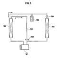
- Patent Document 1 Japanese Patent Application Laid-open No. H2-293570 proposes a refrigeration cycle having a compressor 101, a condenser 102, an accumulator 103, a decompression unit 104 and an evaporator 105, in which an oil separating unit is provided in a refrigerant inflow chamber of the condenser 102, and the separated oil is returned to the compressor 101 from an oil return passage 108 through a decompression valve 109.
- Patent Document 1 has an adverse possibility that a liquid refrigerant flows into the compressor 101.
- an object of the present invention to provide an internal heat exchanger capable of suppressing adhesion of an oil film to an inner surface of a flow path, preventing a heat exchange amount from being reduced, and preventing a liquid refrigerant from flowing into a compressor.
- the invention according to claim 1 provides an internal heat exchanger provided in a refrigeration cycle comprising a radiator which discharges, to outside, heat of a refrigerant circulating in the cycle for cooling the refrigerant, an evaporator which allows the refrigerant circulating in the cycle to absorb heat of outside and which evaporates the refrigerant, a compressor which sucks a refrigerant flowing out from the evaporator, which compresses the refrigerant and discharges the same toward the radiator, and a decompression unit which decompresses the refrigerant flowing out from the radiator and which introduces the same to the evaporator, in which the internal heat exchanger includes a high pressure side flow path through which a high temperature and high pressure refrigerant flowing into the decompression unit from the radiator flows, and a low pressure side flow path through which a low temperature and low pressure refrigerant flowing into a suction side of the compressor from the evaporator flows, and in which heat is exchanged between the high
- Claim 2 provides the internal heat exchanger according to claim 1, wherein the inlet portion of the high pressure side flow path and the inlet portion of the low pressure side flow path are provided with a high pressure side inlet header and a low pressure side inlet header, respectively, and at least one of the high pressure side inlet header and the low pressure side inlet header is provided therein with the oil separating unit.
- Claim 3 provides the internal heat exchanger according to claim 1 or 2, wherein the oil separating unit is provided at its downstream side with an oil returning mechanism which returns oil located on the side of one of the flow paths separated by the oil separating unit toward the other flow path.
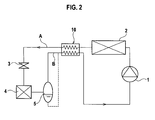
- Fig. 2 is a circuit diagram of a carbon dioxide refrigeration cycle having an internal heat exchanger according to a first embodiment.
- the refrigeration cycle includes a compressor 1 which compresses a refrigerant, a radiator 2 which exchanges heat between outside air and the high temperature refrigerant whose pressure is increased by the compressor 1, an expansion valve (decompressing unit) 3 which decompresses the refrigerant cooled by the radiator 2, an evaporator 4 which evaporates the refrigerant decompressed by the expansion valve 3, an accumulator 5 which separates the refrigerant which passed through the evaporator 4 into gas and liquid and which sends only a vapor phase refrigerant to the compressor 1, and an internal heat exchanger 10 which exchanges heat between the high pressure refrigerant cooled by the radiator 2 and a low pressure refrigerant returning to the compressor 1.
- a compressor 1 which compresses a refrigerant
- a radiator 2 which exchanges heat between outside air and the high temperature refrigerant whose pressure is increased by the compressor 1
- an expansion valve (decompressing unit) 3 which decompresses the refrigerant cooled by the
- the compressor 1 obtains a driving force from a motor or an engine (not shown), compresses a vapor phase carbon dioxide refrigerant (hereinafter, where appropriate, referred to as carbon dioxide or refrigerant), and discharges a high temperature and high pressure refrigerant.
- a vapor phase carbon dioxide refrigerant hereinafter, where appropriate, referred to as carbon dioxide or refrigerant
- the radiator 2 radiates heat of the high temperature and high pressure refrigerant discharged from the compressor 1 to outside air, thereby cooling the refrigerant to a temperature close to the outside air temperature.
- An electric fan is driven to blow outside air to the radiator 2. Heat is exchanged between the outside air blown by the electric fan and the high temperature and high pressure refrigerant passing through the radiator 2, thereby cooling the high temperature and high pressure refrigerant to a predetermined temperature.
- the internal heat exchanger 10 exchanges heat between the refrigerant cooled by the radiator 2 and a low temperature and low pressure refrigerant evaporated by the evaporator 4, thereby further cooling the refrigerant which is sent from the radiator 2 to the expansion valve 3.
- the expansion valve 3 expands (decompresses) a medium temperature and high pressure refrigerant which is cooled by the internal heat exchanger 10, and sends the same to the evaporator 4 as a low temperature and low pressure gaseous refrigerant.
- the evaporator 4 is a heat exchanger which exchanges heat between a low temperature and low pressure refrigerant decompressed by the expansion valve 3 and air supplied from a blower fan (not shown) .
- the refrigerant whose temperature and pressure are reduced by the expansion valve 3 draws heat of supplied air and vaporizes (evaporates) when the refrigerant passes through the evaporator 4.
- the supplied air whose heat is absorbed by the refrigerant in the evaporator 4 is cooled and dehumidified and becomes air conditioned air, and is sent to a vehicle room.
- the accumulator (gas/liquid separator) 5 separates the refrigerant discharged from the evaporator 4 into gas and liquid, sends out the gas phase refrigerant (gaseous refrigerant) into the internal heat exchanger 10, and temporarily stores the liquid phase refrigerant (liquid refrigerant).
- the high temperature and high pressure carbon dioxide discharged from the compressor 1 exchanges heat with air while passing through the radiator 2 and the temperature of the carbon dioxide is lowered.
- the carbon dioxide whose temperature is lowered exchanges heat with a low temperature and low pressure refrigerant which returns to the compressor 1 while the carbon dioxide passes through the internal heat exchanger 10 and the temperature of the carbon dioxide is further lowered and the carbon dioxide is sent to the expansion valve 3.
- the carbon dioxide passes through the expansion valve 3
- the carbon dioxide expands and the temperature thereof is lowered and as a result, the temperature of the evaporator 4 provided downstream of the expansion valve 3 is lowered. Therefore, air passing through the evaporator 4 is cooled, water vapor included in this air is removed, and it is possible to cool and dehumidify air.
- the carbon dioxide exchanges heat in the internal heat exchanger 10 with carbon dioxide (high temperature and high pressure side refrigerant A) which is sent out from the radiator 2 and which is still warm, and is again returned to the compressor 1 and compressed.
- the accumulator 5 also functions to prevent the liquid carbon dioxide from being sent to the compressor 1.
- Figs. 3 show a structure of the internal heat exchanger of the first embodiment, where (a) is a front view and (b) is a sectional view taken along the line I-I' in (a).
- the internal heat exchanger 10 exchanges heat between the high temperature and high pressure side refrigerant A flowing through the high pressure side flow path 11 and the low temperature and low pressure side refrigerant B flowing through a low pressure side flow path 12.
- the high pressure side flow path 11 and the low pressure side flow path 12 have porous pipe portions 11c and 12c in which a plurality of rows of flow paths (not shown) each having a circular cross section are formed, and a refrigerant flows through each flow path.
- the high pressure side flow path 11 has an inlet portion 11a and an outlet portion 11b which are respectively provided with a high pressure side inlet header 21 and a high pressure side outlet header 22.
- the low pressure side flow path 12 has an inlet portion 12a and an outlet portion 12b which are respectively provided with a low pressure side inlet header 31 and a low pressure side outlet header 32.
- These headers 21, 22, 31, and 32 are provided uprightly, and respectively connected to ends of the porous pipe portions 11c and 12c of the high pressure side flow path 11 and the low pressure side flow path 12.
- a high pressure side inlet pipe 21a and a low pressure side inlet pipe 31a are connected to upper ends (upstream sides) of the high pressure side inlet header 21 and the low pressure side inlet header 31, respectively.
- a high pressure side outlet pipe 22a and a low pressure side outlet pipe 32a are connected to lower ends (downstream sides) of the high pressure side outlet header 22 and the low pressure side outlet header 32, respectively.
- An oil separating unit 50 is incorporated in each of the high pressure side inlet header 21 and the low pressure side inlet header 31 at upper positions therein.
- a mesh or a bunch made of metal, resin or fiber such as ceramic, or a porous body made of such material can be used as the oil separating unit 50.
- the oil separating unit 50 Since oil separated by the oil separating unit 50 has greater density than that of the refrigerant, the oil moves downward, and is stored in lower portions of the inlet headers 21 and 31 and flows toward the outlet headers 22 and 32 through flow paths provided below the porous pipe portions 11c and 12c of the high pressure side flow path 11 and the low pressure side flow path 12. That is, the refrigerant passes through the upper flow path and oil flows through the lower flow path and flows into the outlet headers 22 and 32.
- the flow path through which oil flows is limited to flow paths located below the porous pipe portions 11c and 12c, and this can prevent oil from adhering to an inner surface of the flow path through which the refrigerant flows. Therefore, it is possible to prevent the deterioration of the heat exchange amount which is caused by adhesion of oil to the inner surface of the flow path through which the refrigerant flows.
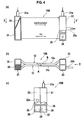
- Figs. 4 show the structure of the internal heat exchanger 10B according to the second embodiment, where (a) is a front view, (b) is a sectional view taken along the line II-II' in (a), and (c) is a side view as viewed from the arrow III in (a).
- the high pressure side inlet header 21 and the low pressure side outlet header 32 adjoin each other, and the high pressure side outlet header 22 and the low pressure side inlet header 31 adjoin each other.
- the oil separating unit 50 is provided at an upper location in the high pressure side inlet header 21, the low pressure side inlet header 31 has no oil separating unit 50.
- Oil chambers 26 and 36 are respectively formed in a downstream side inner bottom portion of the high pressure side outlet header 22 and a downstream side inner bottom portion of the low pressure side inlet header 31.
- the oil chambers 26 and 36 are respectively partitioned from the upper side portion of the high pressure side outlet header 22 and the low pressure side inlet header 31 by division walls 25 and 35.
- These oil chambers 26 and 36 are in communication with each other through a communication hole (e.g., fine hole) 28 formed in a partition wall 27 which partitions the headers 22 and 31 from each other.
- the communication hole 28 has a decompression function.
- the high pressure side outlet pipe 22a is connected to the upper side portion of the high pressure side outlet header 22 on upper side of the partition wall 25 which defines the upper side of the oil chamber 26.
- oil separated by the oil separating unit 50 of the high pressure side inlet header 21 stays in a lower portion of the header 21 and flows toward the high pressure side outlet header 22 through a flow path located below the porous pipe 11c.
- the oil which flowed to the oil chamber 26 of the lower portion of the high pressure side outlet header 22 flows into the oil chamber 36 at a lower portion of the low pressure side inlet header 31 through the communication hole 28 having the decompression function, and flows into the low pressure side outlet header 32 through a flow path located below the porous pipe 12 from the oil chamber 36.
- the refrigerant and the oil are mixed in the low pressure side outlet header 32, and the refrigerant in which the oil is mixed from the low pressure side outlet pipe (not shown) flows into the compressor 1.
- the flow path located below the porous pipe 11c, the oil chamber 26 and the communication hole 28 function as an oil returning mechanism located downstream of the oil separating unit 50.
- the internal heat exchanger 10B when a refrigerant flows through the porous pipes 11c and 12c, i.e., when a refrigerant flows from the high pressure side inlet header 21 to the high pressure side outlet header 22, and when the refrigerant flows from the low pressure side inlet header 31 to the low pressure side outlet header 32, since the refrigerant and the oil flow in a state where they are separated into an upper layer and a lower layer, it is possible to prevent the oil from adhering to the inner surface of the flow path in a range where the refrigerant flows, and it is possible to avoid a case that the heat exchange amount of the internal heat exchanger 10B is reduced by the adhesion of oil.
- FIGs. 5 show an internal heat exchanger 10C according to a third embodiment in which the invention is applied to the parallel flow.
- Fig. 5(a) is a front view of the internal heat exchanger of the third embodiment,
- (b) is a sectional view taken along the line IV-IV' in (a), and
- (c) is a side view as viewed from the arrow V in (a).
- the high pressure side inlet header 21 and the low pressure side inlet header 31 adjoins each other, and the high pressure side outlet header 22 and the low pressure side outlet header 32 adjoin each other.
- the oil separating unit 50 is provided at an upper position in the high pressure side inlet header 21, and the low pressure side inlet header 31 has no oil separating unit 50.
- Oil chambers 26 and 36 are respectively provided in a downstream side inner bottom portion of the high pressure side inlet header 21 and a downstream side inner bottom portion of the low pressure side inlet header 31.
- the oil chambers 26 and 36 are respectively partitioned from the upper side portion of the high pressure side inlet header 21 and the low pressure side inlet header 31 by division walls 25 and 35.
- These oil chambers 26 and 36 are in communication with each other through a communication hole (e. g. , fine hole) 28 provided in a partition wall 27 which partitions the headers 21 and 31 from each other.
- the communication hole 28 has a decompression function.
- oil separated by the oil separating unit 50 in the high pressure side inlet header 21 stays in the lower oil chamber 26 of the header 21, and flows into the oil chamber 36 of the low pressure side inlet header 31 through the communication hole 28 having the decompression function as it is.
- the oil passes through a flow path located below the porous pipe 12 from the oil chamber 36 and flows into the low pressure side outlet header 32.
- the oil and the refrigerant are mixed in the low pressure side outlet header 32, and the oil mixture coming from the low pressure side outlet pipe (not shown) flows into the compressor 1.
- the oil chamber 26 and the communication hole 28 function as the oil returning mechanism.
- the high pressure side inlet header 21 and the low pressure side outlet header 32 immediately adjoin each other, and the high pressure side outlet header 22 and the low pressure side inlet header 31 immediately adjoin each other (they are integrally formed in the illustrated example). Therefore, heat is exchanged also between the adjacent headers 21 and 32, and between the adjacent headers 22 and 31.
- the high pressure side inlet header 21 and the low pressure side inlet header 31 immediately adjoin each other, and the high pressure side outlet header 22 and the low pressure side outlet header 32 immediately adjoin each other (they are integrally formed in the illustrated example). Therefore, heat is exchanged also between the adjacent headers 21 and 31, and between the adjacent headers 22 and 32.
- the headers 21, 22, and 31 can be provided at their outsides with elements having the same functions as the decompression function and these headers may be used instead of the communication hole 28.
- a communication pipe having a decompression function which brings the oil chambers 26 and 36 into communication with each other may be provided outside of the header.
- the structure of the oil chambers 26 and 36 and the communication pipe may be applied also to an internal heat exchanger of a type in which the high pressure and low pressure headers 21, 22, 31, and 32 are separated from each other as shown in Fig. 3 .
- FIG. 6 is an exploded perspective view of an internal heat exchanger according to a fourth embodiment, and particularly shows the oil returning structures provided in the high pressure side inlet header 21 and the low pressure side outlet header 32. Explanations of the same structures and effects as those of other embodiments will be omitted, and only structures and effects specific to the present embodiment are explained.
- the high pressure side inlet header 21 and the low pressure side outlet header 32 are adjacent to each other, and a high pressure side outlet header and a low pressure side inlet header (both not shown) are adjacent to each other.
- an oil separating unit (see Fig. 3(b) ) is provided at an upper position in the high pressure side inlet header 21.
- the low pressure side inlet header (not shown) has no oil separating unit.
- a patch end 41 and a plate 42 are provided at lower ends of the adjacent high pressure side inlet header 21 and low pressure side outlet header 32, and the adjacent two headers are connected to each other.
- the patch end 41 is formed into a box-frame shape.
- the patch end 41 is provided at its bottom with a groove 41a through which the high pressure side inlet header 21 and the low pressure side outlet header 32 are communicated with each other, and an outlet hole 41b for discharging a refrigerant from a lower end of the low pressure side outlet header 32.
- a cross section of the groove 41a has a substantially recess shape, and its end is in communication with the outlet hole 41b.
- a low pressure side outlet pipe 32a is connected to the outlet hole 41b of the patch end 41.
- the patch end 41 can be formed by cutting, press, forging or the like.
- the lower end of the high pressure side inlet header 21 is shut off, and the lower end of the low pressure side outlet header 32 and the low pressure side outlet pipe 32a are brought into communication with each other through the groove 41a.
- the adjacent high pressure side inlet header 21 and the low pressure side outlet header 32 are connected and fixed to each other through the patch end 41 and the plate 42.
- oil separated by the oil separating unit (not shown) provided in the high pressure side inlet header 21 is accumulated in the lower portion of the high pressure side inlet header 21, and the oil flows from here to the lower portion of the low pressure side outlet header 32 through the groove 41a of the patch end 41.
- a refrigerant and oil flowing through the porous pipe 12 in the lower portion of the low pressure side outlet header 32 are mixed, and the refrigerant in which oil is mixed is discharged from the low pressure side outlet pipe 32a and is sent to the compressor 1.
- the patch end 41, the plate 42 and the groove 41a function as the oil returning mechanism provided downstream of the oil separating unit.
- oil can be returned by the simple structures formed by the patch end 41 and the plate 42, the number of parts can be reduced and the costs can be reduced.
- the oil returning structure formed by the patch end 41 and the plate 42 is provided at the lower portions of the high pressure side inlet header 21 and the low pressure side outlet header 32 in the present embodiment, the same oil returning structure may be provided at the high pressure side outlet header and the low pressure side inlet header (both not shown) and oil may be returned from the lower portion of the low pressure side inlet header to the high pressure side outlet header.
- One or both of the headers may be provided with the oil returning structure.
- the one groove 41a is formed in the bottom of the patch end 41 in the present embodiment, a plurality of grooves 41a may be formed.
- a groove having the decompression function may be formed by reducing the cross-sectional area.
- Fig. 7 is an exploded perspective view of an internal heat exchanger according to a fifth embodiment, and especially shows oil returning structures provided in the high pressure side inlet header 21 and the low pressure side inlet header 32. Explanations of the same structures and effects as those of other embodiments will be omitted, and only structures and effects specific to the present embodiment are explained.
- a refrigerant flows in the parallel flow manner as in the third embodiment, the high pressure side inlet header 21 and the low pressure side inlet header 32 are disposed adjacent to each other, and the high pressure side outlet header and the low pressure side outlet header (both not shown) are also disposed adjacent to each other.
- oil separating unit (see Fig. 3(b) ) (not shown) is provided at an upper position in the high pressure side inlet header 21.
- the low pressure side inlet header 32 has no oil separating unit.
- a patch end 43 and a plate 42 are provided at lower ends of the adjacent high pressure side inlet header 21 and low pressure side inlet header 32, and the adjacent two headers are connected to each other.
- the patch end 43 is formed into a box-frame shape.
- the patch end 43 is provided at its bottom with a groove 43a through which the high pressure side inlet header 21 and the low pressure side inlet header 32 are communicated with each other.
- a cross section of the groove 43a has a recess shape.
- the lower ends of the high pressure side inlet header 21 and the low pressure side inlet header 32 are shut off, and the lower ends of the headers are in communication with each other through the groove 43a.
- the adjacent high pressure side inlet header 21 and low pressure side inlet header 32 are connected and fixed to each other through the patch end 43 and the plate 42.
- oil separated by the oil separating unit (not shown) provided in the high pressure side inlet header 21 is accumulated in the lower portion of the header 21, and the oil flows into the lower portion of the low pressure side inlet header 32 through the groove 43a of the patch end 43, and flows into the low pressure side outlet header (not shown) through a flow path of the porous pipe 12 located below the low pressure side inlet header 32.
- a refrigerant and oil are mixed in the low pressure side outlet header, and the refrigerant in which oil is mixed is discharged from the low pressure side outlet pipe (not shown) and is sent to the compressor 1.
- the patch end 43, the plate 42 and the groove 43a function as the oil returning mechanism provided downstream of the oil separating unit.
- oil can be returned by the simple structures formed by the patch end 43 and the plate 42, the number of parts can be reduced and the costs can be reduced.
- the oil returning structure formed by the patch end 43 and the plate 42 is provided at the lower portions of the high pressure side inlet header 21 and the low pressure side inlet header 32, but the oil returning structure as shown in Fig. 7 or 6 may be provided at the high pressure side outlet header (not shown) and the low pressure side outlet header (not shown), and oil may be returned to the low pressure side outlet header from the lower portion of the high pressure side outlet header.
- One or both of the headers may be provided with the oil returning structure in this manner.
- groove 43a is formed in the bottom of the patch end 43 in the present embodiment, a plurality of grooves 43a may be formed.
- a groove having the decompression function may be formed by reducing the cross-sectional area.
- an internal heat exchanger capable of suppressing the adhesion of oil film on an inner surface of a flow path, preventing a heat exchange amount from being reduced, and preventing a liquid refrigerant from flowing into a compressor.
Landscapes
- Engineering & Computer Science (AREA)
- Physics & Mathematics (AREA)
- Thermal Sciences (AREA)
- Mechanical Engineering (AREA)
- General Engineering & Computer Science (AREA)
- Heat-Exchange Devices With Radiators And Conduit Assemblies (AREA)
- Air-Conditioning For Vehicles (AREA)
Applications Claiming Priority (2)
| Application Number | Priority Date | Filing Date | Title |
|---|---|---|---|
| JP2006115449 | 2006-04-19 | ||
| PCT/JP2007/058060 WO2007123041A1 (ja) | 2006-04-19 | 2007-04-12 | 内部熱交換器 |
Publications (1)
| Publication Number | Publication Date |
|---|---|
| EP2017555A1 true EP2017555A1 (de) | 2009-01-21 |
Family
ID=38624946
Family Applications (1)
| Application Number | Title | Priority Date | Filing Date |
|---|---|---|---|
| EP07741496A Withdrawn EP2017555A1 (de) | 2006-04-19 | 2007-04-12 | Innerer wärmetauscher |
Country Status (3)
| Country | Link |
|---|---|
| EP (1) | EP2017555A1 (de) |
| JP (1) | JPWO2007123041A1 (de) |
| WO (1) | WO2007123041A1 (de) |
Cited By (1)
| Publication number | Priority date | Publication date | Assignee | Title |
|---|---|---|---|---|
| EP3249340A1 (de) * | 2016-05-17 | 2017-11-29 | United Technologies Corporation | Wärmetauscher mit verminderter kernquerschnittsfläche |
Families Citing this family (1)
| Publication number | Priority date | Publication date | Assignee | Title |
|---|---|---|---|---|
| WO2013114474A1 (ja) * | 2012-01-30 | 2013-08-08 | 三菱電機株式会社 | 積層型熱交換器及びそれを搭載したヒートポンプシステム、並びに積層型熱交換器の製造方法 |
Family Cites Families (5)
| Publication number | Priority date | Publication date | Assignee | Title |
|---|---|---|---|---|
| JPH02293570A (ja) | 1989-05-08 | 1990-12-04 | Nippondenso Co Ltd | 冷媒凝縮器 |
| JP4727051B2 (ja) * | 2001-02-14 | 2011-07-20 | 三菱重工業株式会社 | インタークーラ及びco2冷媒車両用空調装置 |
| JP4718716B2 (ja) * | 2001-05-01 | 2011-07-06 | 三菱重工業株式会社 | ガスクーラ及び車載用空調装置 |
| JP2004092933A (ja) * | 2002-08-29 | 2004-03-25 | Zexel Valeo Climate Control Corp | 冷凍サイクル |
| JP4108509B2 (ja) * | 2003-03-06 | 2008-06-25 | 株式会社日本クライメイトシステムズ | 車両用空調装置 |
-
2007
- 2007-04-12 JP JP2008512080A patent/JPWO2007123041A1/ja active Pending
- 2007-04-12 WO PCT/JP2007/058060 patent/WO2007123041A1/ja not_active Ceased
- 2007-04-12 EP EP07741496A patent/EP2017555A1/de not_active Withdrawn
Non-Patent Citations (1)
| Title |
|---|
| See references of WO2007123041A1 * |
Cited By (2)
| Publication number | Priority date | Publication date | Assignee | Title |
|---|---|---|---|---|
| EP3249340A1 (de) * | 2016-05-17 | 2017-11-29 | United Technologies Corporation | Wärmetauscher mit verminderter kernquerschnittsfläche |
| US10247004B2 (en) | 2016-05-17 | 2019-04-02 | United Technologies Corporation | Heat exchanger with decreased core cross-sectional areas |
Also Published As
| Publication number | Publication date |
|---|---|
| JPWO2007123041A1 (ja) | 2009-09-03 |
| WO2007123041A1 (ja) | 2007-11-01 |
Similar Documents
| Publication | Publication Date | Title |
|---|---|---|
| US8099978B2 (en) | Evaporator unit | |
| JP4259478B2 (ja) | 蒸発器構造およびエジェクタサイクル | |
| EP1870648B1 (de) | Ausstoss-kühlzykluseinheit | |
| JP4645681B2 (ja) | 蒸発器ユニット | |
| GB2316738A (en) | A combined refrigerant accumulator and heat transfer unit | |
| JP2009293809A (ja) | 熱交換器 | |
| JP5757415B2 (ja) | 空気調和機等の冷凍装置 | |
| EP1347254A1 (de) | Kältemittelkreislauf und Verflüssiger | |
| JP5062066B2 (ja) | エジェクタ式冷凍サイクル用蒸発器ユニット | |
| JP2011058649A (ja) | 熱交換器および冷凍機 | |
| JP4416048B2 (ja) | エジェクタ式冷凍サイクル用ユニット | |
| JP2002333221A (ja) | ガスクーラ及び車載用空調装置 | |
| JP2001174103A (ja) | 冷媒凝縮器 | |
| JP2020139695A (ja) | 圧縮機 | |
| JP4265677B2 (ja) | エジェクタ式冷凍サイクル用ユニット | |
| JP4400522B2 (ja) | エジェクタ式冷凍サイクル | |
| JP2011202921A (ja) | 蒸発器ユニット | |
| JP2008281338A (ja) | エジェクタサイクル | |
| EP2908062A1 (de) | Außeneinheit einer Klimaanlage | |
| JPWO2007123041A1 (ja) | 内部熱交換器 | |
| JP6477306B2 (ja) | 冷媒蒸発器 | |
| US7360373B2 (en) | Vehicle air-conditioning system | |
| JP2008138895A (ja) | 蒸発器ユニット | |
| JPH09126592A (ja) | ヒートポンプ式冷凍サイクル用室外熱交換器 | |
| JP4577291B2 (ja) | 冷媒蒸発器 |
Legal Events
| Date | Code | Title | Description |
|---|---|---|---|
| PUAI | Public reference made under article 153(3) epc to a published international application that has entered the european phase |
Free format text: ORIGINAL CODE: 0009012 |
|
| 17P | Request for examination filed |
Effective date: 20081118 |
|
| AK | Designated contracting states |
Kind code of ref document: A1 Designated state(s): AT BE BG CH CY CZ DE DK EE ES FI FR GB GR HU IE IS IT LI LT LU LV MC MT NL PL PT RO SE SI SK TR |
|
| AX | Request for extension of the european patent |
Extension state: AL BA HR MK RS |
|
| RBV | Designated contracting states (corrected) |
Designated state(s): DE FR GB |
|
| STAA | Information on the status of an ep patent application or granted ep patent |
Free format text: STATUS: THE APPLICATION HAS BEEN WITHDRAWN |
|
| 18W | Application withdrawn |
Effective date: 20100331 |