WO2013114474A1 - 積層型熱交換器及びそれを搭載したヒートポンプシステム、並びに積層型熱交換器の製造方法 - Google Patents
積層型熱交換器及びそれを搭載したヒートポンプシステム、並びに積層型熱交換器の製造方法 Download PDFInfo
- Publication number
- WO2013114474A1 WO2013114474A1 PCT/JP2012/003943 JP2012003943W WO2013114474A1 WO 2013114474 A1 WO2013114474 A1 WO 2013114474A1 JP 2012003943 W JP2012003943 W JP 2012003943W WO 2013114474 A1 WO2013114474 A1 WO 2013114474A1
- Authority
- WO
- WIPO (PCT)
- Prior art keywords
- heat transfer
- refrigerant
- heat exchanger
- transfer tube
- heat
- Prior art date
Links
Images


Classifications
-
- F—MECHANICAL ENGINEERING; LIGHTING; HEATING; WEAPONS; BLASTING
- F25—REFRIGERATION OR COOLING; COMBINED HEATING AND REFRIGERATION SYSTEMS; HEAT PUMP SYSTEMS; MANUFACTURE OR STORAGE OF ICE; LIQUEFACTION SOLIDIFICATION OF GASES
- F25B—REFRIGERATION MACHINES, PLANTS OR SYSTEMS; COMBINED HEATING AND REFRIGERATION SYSTEMS; HEAT PUMP SYSTEMS
- F25B25/00—Machines, plants or systems, using a combination of modes of operation covered by two or more of the groups F25B1/00 - F25B23/00
- F25B25/005—Machines, plants or systems, using a combination of modes of operation covered by two or more of the groups F25B1/00 - F25B23/00 using primary and secondary systems
-
- F—MECHANICAL ENGINEERING; LIGHTING; HEATING; WEAPONS; BLASTING
- F28—HEAT EXCHANGE IN GENERAL
- F28D—HEAT-EXCHANGE APPARATUS, NOT PROVIDED FOR IN ANOTHER SUBCLASS, IN WHICH THE HEAT-EXCHANGE MEDIA DO NOT COME INTO DIRECT CONTACT
- F28D9/00—Heat-exchange apparatus having stationary plate-like or laminated conduit assemblies for both heat-exchange media, the media being in contact with different sides of a conduit wall
- F28D9/0081—Heat-exchange apparatus having stationary plate-like or laminated conduit assemblies for both heat-exchange media, the media being in contact with different sides of a conduit wall the conduits for one heat-exchange medium being formed by a single plate-like element ; the conduits for one heat-exchange medium being integrated in one single plate-like element
-
- F—MECHANICAL ENGINEERING; LIGHTING; HEATING; WEAPONS; BLASTING
- F28—HEAT EXCHANGE IN GENERAL
- F28F—DETAILS OF HEAT-EXCHANGE AND HEAT-TRANSFER APPARATUS, OF GENERAL APPLICATION
- F28F9/00—Casings; Header boxes; Auxiliary supports for elements; Auxiliary members within casings
- F28F9/02—Header boxes; End plates
- F28F9/0219—Arrangements for sealing end plates into casing or header box; Header box sub-elements
- F28F9/0221—Header boxes or end plates formed by stacked elements
Definitions
- the present invention relates to a stacked heat exchanger that performs heat exchange between a first refrigerant and a second refrigerant that are a low-temperature fluid or a high-temperature fluid, a heat pump system that includes the heat exchanger, and a method for manufacturing the stacked heat exchanger.
- a first heat transfer tube through which a low-temperature fluid flows and a second heat transfer tube arranged such that a high-temperature fluid flows and the flow direction of the high-temperature fluid is parallel to the flow direction of the low-temperature fluid are alternately arranged.
- the heat exchanger is formed by stacking at least one heat transfer tube with a plurality of heat transfer tubes arranged in the stacking direction, and both ends of the plurality of heat transfer tubes are arranged in either the flow direction or the stacking direction of each fluid. Also, it is configured to be bent in a direction orthogonal to the above.
- a parallel flow path is constituted by the plurality of heat transfer tubes and the inlet header and the outlet header, either the inlet header or the outlet header is constituted by a tubular header, and the plurality of heat transfer pipes constituting the parallel flow path are provided.
- Some are bundled and connected so that the tube axis direction of the tubular header and the fluid flow direction of the heat transfer tube are perpendicular to each other (for example, see Patent Document 1).
- the heat exchanger described in Patent Document 1 has a structure in which heat transfer tubes are stacked, although it has high performance and high space efficiency, at least one of the header tubes into which the refrigerant flows is perpendicular to the stacking direction. Since it has the structure connected with the heat exchanger tube bent in the direction, there existed a problem that it had the bending process to the width direction of the heat exchanger tube at that time, and the dead space by a header pipe increased.
- the present invention has been made to solve the above-mentioned problems, and eliminates a heat transfer tube bending step, and a stacked heat exchanger without a dead space by a header tube, a heat pump system equipped with the heat exchanger system, and a stacked heat exchange It aims at obtaining the manufacturing method of a vessel.
- the laminated heat exchanger according to the present invention has a flat shape, a plurality of first heat transfer tubes in which the first refrigerant flows through a first refrigerant flow path therein, and a flat shape.
- a plurality of second heat transfer tubes that are stacked together with a heat pipe and in which a second refrigerant having a temperature different from that of the first refrigerant flows through a second refrigerant flow path therein; and the first refrigerant flow paths of the first heat transfer tubes, And each said 1st heat exchanger tube and each said 2nd heat exchanger tube are obstruct
- the first refrigerant flow paths are communicated with each other. And it is located in the both ends of the lamination direction in the laminated structure of each said 1st heat exchanger tube and each said 2nd heat exchanger tube. The first refrigerant flow path and the outside are communicated with each other in the closing means joined to one of the two outermost heat transfer tubes, which is the first heat transfer tube or the second heat transfer tube.
- the second refrigerant flow As described above, in the first communication hole formed so as to penetrate, the closing means joined to the first heat transfer tubes, and the closing means joined to the second heat transfer tubes, the second refrigerant flow
- the passages are communicated with each other, and the second refrigerant flow paths and the outside are communicated with each other in the blocking means joined to one of the two outermost heat transfer tubes.
- the first communication hole formed in the closing means joined to each second heat transfer tube is blocked so as not to communicate with the second refrigerant flow path.
- Second blocking means for blocking the formed second communication hole so as not to communicate with the first refrigerant flow path, and two sets of the first communication holes are formed, and the second communication holes are Two sets of two first communication holes formed in the closing means joined to the outermost heat transfer tube and communicating with each first refrigerant flow path and the outside are respectively connected to the flow of the first refrigerant.
- the two second communication holes that function as an inlet and an outlet and are formed in the blocking means joined to the outermost heat transfer tube and communicate with the second refrigerant flow paths and the outside are respectively the second refrigerant. It functions as an inflow port and an outflow port.
- the closing means includes the first communication hole for communicating the first refrigerant flow path of each first heat transfer tube and the second communication hole for communicating the second refrigerant flow path of each second heat transfer tube.
- FIG. 10 It is a perspective view of the heat exchanger 10 which is a laminated heat exchanger which concerns on Embodiment 1 of this invention. It is a three-view figure of the heat exchanger 10 which is a laminated heat exchanger which concerns on Embodiment 1 of this invention. It is a three-view figure of the lid
- FIG. 1 is a perspective view of a heat exchanger 10 that is a stacked heat exchanger according to Embodiment 1 of the present invention
- FIG. 2 is a three-sided view of the heat exchanger 10
- FIG. FIG. 3 is a three-side view of the lid 8 that is brazed to the heat transfer tube end of the heat exchanger 10.
- the configuration of the heat exchanger 10 that is the stacked heat exchanger according to the present embodiment will be described with reference to FIGS. 1 to 3.
- it demonstrates according to the up-down and left-right direction of FIG.
- the heat exchanger 10 has a refrigerant flow path in which the refrigerant flows in a rectangular shape, and has substantially the same length in the refrigerant flow direction of the refrigerant flow path.
- a plurality of flat first heat transfer tubes 1 and second heat transfer tubes 2 having substantially the same length in the width direction of the refrigerant flow path are alternately stacked.
- the first heat transfer tubes 1 and the second heat transfer tubes 2 are brazed and joined by a brazing material 21 such as an aluminum-silicon system.
- coolant flow path which penetrates the 1st heat exchanger tube edge part 5 which is the edge part of the both ends of the 1st heat exchanger tube 1 is made into the 1st refrigerant
- a rectangular refrigerant flow path penetrating through the second heat transfer tube end portion 6 that is the end portions at both ends of the second heat transfer tube 2 is referred to as a second refrigerant flow channel 2a.
- the first refrigerant flow path 1a at the first heat transfer tube end 5 and the second refrigerant flow path 2a at the second heat transfer tube end 6 are respectively closed by a lid 8. As shown in FIG.
- the lid 8 is formed with a lid hole-shaped portion 8c by making a hole in a rectangular shape from the side surface closing the first refrigerant channel 1a and the second refrigerant channel 2a.
- a rectangular sealing material 8a is installed at one corner on the back side.
- This sealing material 8a includes a rear side inner wall surface and a side surface inner wall surface in a plan view shown in FIG. 3A (a plan view of the lid 8), and FIG. 3B (a front view of the lid 8).
- FIG. 3A a plan view of the lid 8
- FIG. 3B a front view of the lid 8
- cover 8 is joined so that the 1st refrigerant
- the portion 8c is configured to communicate with each of the first refrigerant channel 1a and the second refrigerant channel 2a.
- the lid 8 joined to the first heat transfer tube end 5 of the first heat transfer tube 1 and the lid 8 joined to the second heat transfer tube end 6 of the second heat transfer tube 2 are mutually connected by the brazing material 21. It is joined.
- the sealing material 8a is in contact with the inner wall surface on the back side and the inner wall surface on the side surface in a plan view, but is not limited thereto. In particular, it does not need to be in contact.
- the sealing material 8a installed in the lid hole shape portion 8c is rectangular, it is not limited to this, and may be other shapes such as a circular shape or an elliptical shape.
- the lid 8 corresponds to the “closing means” of the present invention.
- sealing material 8a of the lid 8 joined to the second heat transfer tube 2 corresponds to the “first blocking means” of the present invention
- the sealing material 8a of the lid 8 joined to the first heat transfer tube 1 is Corresponds to the “second blocking means” of the present invention.
- the position of the sealing material 8a of the lid 8 joined to the first heat transfer tube end portion 5 of all the first heat transfer tubes 1 is set to be the same corner in the lid hole shape portion 8c.
- the position of the sealing material 8a of the lid 8 joined to the second heat transfer tube end portion 6 of all the second heat transfer tubes 2 is the same as the sealing material 8a of the lid 8 installed in the first heat transfer tube 1. Is installed in the lid hole shape portion 8c so as to be one corner on the opposite side.
- both ends of the uppermost heat transfer tube (the first heat transfer tube 1 in FIGS. 1 and 2) of the laminated structure of the first heat transfer tube 1 and the second heat transfer tube 2 are used.
- the tubular first port 3 communicating with the first refrigerant flow path 1a of the first heat transfer tube 1 and the second refrigerant flow of the second heat transfer tube 2 are formed on the upper surface of the lid 8 joined to the first heat transfer tube 1.
- Tubular second ports 4 communicating with the path 2a are brazed with a brazing material 21, respectively.
- Two first ports 3 and two second ports 4 are provided for refrigerant inlet and outlet, respectively, and are connected to a refrigerant circuit or the like in the heat pump system.
- the uppermost heat transfer tube in the laminated structure of the heat transfer tubes is the first heat transfer tube 1, but is not limited to this, and the second heat transfer tube 2 is not limited to this. It goes without saying that the top row may be used.
- the first port 3 and the second port 4 are installed on the lid 8 joined to both ends of the uppermost heat transfer tube in the laminated structure of the heat transfer tubes.
- the present invention is not limited to this, the first port 3 and the second port 4 are not installed, and the communication hole formed in the lid 8 joined to both ends of the uppermost heat transfer tube is used as a connection port. Piping such as a refrigerant circuit in the heat pump system may be directly connected.
- FIG. 2A is a plan view of the heat exchanger 10 according to the present embodiment
- FIG. 2B is a cross-sectional view taken along the line AA in FIG. 2A
- FIG. ) Is a side view of the heat exchanger 10.
- 3 (a) is a plan view of the lid 8 of the heat exchanger 10
- FIG. 3 (b) is a front view of the lid 8
- FIG. 3 (c) is the same lid.
- the laminated structure of the lid 8 provided on both sides of the laminated structure of the first heat transfer tube 1 and the second heat transfer tube 2 has a 180-degree rotationally symmetric structure around the laminated structure of the heat transfer tubes, as shown in FIG.
- a cross-sectional view along A′-A ′ in a) is also as shown in FIG.
- the first communication hole 3a is formed through the upper and lower surfaces of the lid 8 joined to the uppermost first heat transfer tube 1.
- the first port 3 communicates with the first refrigerant flow path 1a through the first communication hole 3a on the upper surface of the lid 8.
- the first communication hole 3 a formed in the lower surface of the lid 8 is a first communication hole formed so as to penetrate the upper surface of the lid 8 joined to the second heat transfer tube 2 directly below the first heat transfer tube 1. It communicates with 3b.
- the stop material communication hole 8b is formed to penetrate therethrough.
- the sealing material communication hole 8 b further communicates with a first communication hole 3 b formed through the lower surface of the lid 8.
- the first heat transfer tube 1 directly below the second heat transfer tube 2 includes a first heat transfer tube 1 on the upper surface and the lower surface of the lid 8 joined to the first heat transfer tube 1, similarly to the uppermost first heat transfer tube 1.
- the communication hole 3a is penetrated, and the first communication hole 3b on the lower surface of the lid 8 joined to the second heat transfer pipe 2 immediately above the first heat transfer pipe 1 is joined to the first heat transfer pipe 1 among them.
- the lid 8 communicates with the first refrigerant flow path 1a through the first communication hole 3a on the upper surface.
- the first port 3 communicates with the first refrigerant flow path 1a of the uppermost first heat transfer tube 1, and the first refrigerant flow path 1a further passes through the second heat transfer tube 2 directly below the first refrigerant flow path 1a. Furthermore, it communicates with the first refrigerant flow path 1a of the first heat transfer tube 1 therebelow.
- coolant flow path 1a of the 1st port 3 and each 1st heat exchanger tube 1 has the structure connected
- cover. 8 has a structure blocked by the sealing material 8a.
- the first communication hole 3a is formed only on the upper surface.
- the refrigerant flowing from one of the two first ports 3 (hereinafter referred to as the first refrigerant) flows through the first refrigerant flow path 1a of each first heat transfer tube 1 in the laminated structure. , Flows out from the other first port 3.
- a second communication hole 4 a is formed through the upper surface of the lid 8 joined to the uppermost first heat transfer tube 1, and the second port 4 is connected to the upper surface of the lid 8. It communicates with the hole 4a.
- the stop material communication hole 8b is formed to penetrate therethrough.
- the sealing material communication hole 8b further communicates with a second communication hole 4a formed through the lower surface of the lid 8.
- a second communication hole 4b is formed through the upper and lower surfaces of the lid 8 joined to the second heat transfer tube 2 directly below the first heat transfer tube 1, and the second heat transfer tube 2
- the second communication hole 4a on the lower surface of the lid 8 joined to the first heat transfer tube 1 directly above is connected to the second communication hole 4b on the upper surface of the lid 8 joined to the second heat transfer tube 2 through the second communication hole 4b. It communicates with the refrigerant flow path 2a.
- the second communication hole 4 b formed on the lower surface of the second heat transfer tube 2 penetrates the upper surface of the lid 8 joined to the first heat transfer tube 1 directly below the second heat transfer tube 2. It communicates with the two communication holes 4a.
- a sealing material 8a exists in a portion communicating with the second communication hole 4a, and the sealing material 8a is sealed so as to communicate with the second communication hole 4a.
- the material communication hole 8b is formed to penetrate therethrough.
- the sealing material communication hole 8b further communicates with a second communication hole 4a formed through the lower surface of the lid 8.
- a second communication hole 4b is formed through the upper and lower surfaces of the lid 8 joined to the second heat transfer tube 2 directly below the first heat transfer tube 1, and the second heat transfer tube 2
- the second communication hole 4a on the lower surface of the lid 8 joined to the first heat transfer tube 1 directly above is connected to the second communication hole 4b on the upper surface of the lid 8 joined to the second heat transfer tube 2 through the second communication hole 4b. It communicates with the refrigerant flow path 2a.
- the second port 4 communicates with the second refrigerant flow path 2a of the second heat transfer pipe 2 immediately below the uppermost first heat transfer pipe 1, and further, the second refrigerant flow path 2a is directly below it.
- the first heat transfer tube 1 is further communicated with the second refrigerant flow path 2a of the second heat transfer tube 2 therebelow.
- the same structure is adopted, and the second refrigerant flow path 2a of the second port 4 and each of the second heat transfer tubes 2 has a communication structure, and the first refrigerant flow path 1a of the first heat transfer tube 1 is a lid. 8 has a structure blocked by the sealing material 8a. However, in the lid 8 joined to the lowermost second heat transfer tube 2 (the lowermost heat transfer tube in FIG.
- the second refrigerant flows through the second refrigerant flow path 2a of each second heat transfer tube 2 in the laminated structure. , And flows out from the other second port 4.
- each of the four first heat transfer tubes 1 and the second heat transfer tubes 2 is configured to be alternately stacked.
- the first heat transfer tube 1 and the second heat transfer tube 2 may be alternately stacked.
- the number of the first heat transfer tubes 1 and the second heat transfer tubes 2 to be stacked is not limited to the same number.
- the number of the first heat transfer tubes 1 is one more than the number of the second heat transfer tubes 2. It is good also as a laminated structure with few or one.
- FIG.1 and FIG.2 it is set as the structure where the 1st heat exchanger tube 1 and the 2nd heat exchanger tube 2 are laminated
- a first refrigerant channel 1a and a second refrigerant channel 2a having a rectangular cross section are formed in the first heat transfer tube 1 and the second heat transfer tube 2, respectively.
- the present invention is not limited to this, and other shapes such as an ellipse may be used.
- the sealing material 8a has a rectangular shape, but is not limited thereto, and may have a different shape as long as the sealing material communication hole 8b can be formed. .
- the planar shape of the first heat transfer tube 1 and the second heat transfer tube 2 is a rectangle, but is not limited to this.
- the four corners of the rectangle are R-shaped.
- the shape may be a parallelogram or the like, or the shape may be appropriately changed depending on the position mounted on the heat pump system or the like.
- 3b and the sealing material communication hole 8b of the sealing material 8a are formed in the same diameter and concentrically in the stacking direction, but are not limited to this, are not the same diameter, or It may be formed so as not to be concentric in the stacking direction, and may be formed so that the first refrigerant flow path 1a of each first heat transfer tube 1 is communicated.
- each second heat transfer tube 2 may be formed so as to communicate with each other.
- each said hole is not limited to circular shape, You may form in other shapes, such as a rectangular shape.
- FIG. 4 is a cross-sectional view of a main part of the heat exchanger 10 that is the stacked heat exchanger according to Embodiment 1 of the present invention
- FIG. 5 is a diagram illustrating a method for manufacturing the heat exchanger 10.
- the first heat transfer tube 1 and the second heat transfer tube 2 of the heat exchanger 10 of the present embodiment shown in FIGS. 1 and 2 are made of a material having good heat conductivity, such as an aluminum alloy, copper, or stainless steel.
- the first heat transfer tube 1 and the second heat transfer tube 2 are alternately stacked, and are brazed and brazed with a brazing material 21 such as an aluminum-silicon base at the contact surfaces of each other. A structure is formed.
- the 1st heat exchanger tube 1 and the 2nd heat exchanger tube 2 were laminated
- the lid 8 is made of a material having good thermal conductivity, such as aluminum alloy, copper, or stainless steel, and the lid 8 and the sealing material 8a are formed as separate parts, or an integrally molded product such as casting or cutting. Configured as a processed product. Further, the first heat transfer tube end portion 5 which is both ends of the first heat transfer tube 1 and the second heat transfer tube end portion 6 which is both ends of the second heat transfer tube 2 are inserted into the lid hole shape portion 8 c of the lid 8.
- the lid mounting portion 9a is formed so as to have a convex shape by cutting so as to be smaller than the cross-sectional area of the flat tube of the first heat transfer tube 1 or the second heat transfer tube 2 so that it can be made.
- the lid 8 has an inner portion of the lid hole-shaped portion 8c so that the cross-sectional area of the lid mounting portion 9a is substantially the same so that the lid mounting portion 9a of the first heat transfer tube 1 or the second heat transfer tube 2 can be inserted.
- the heat transfer tube mounting portion 9b is formed so as to cut the wall surface into a concave shape. 2 and FIG. 3, the structure in which the first port 3 and the first refrigerant flow path 1a of the stacked first heat transfer tube 1 communicate with each other, and the second port 4 and the stacked second heat transfer tube.
- the first communication holes 3a, 3b, the second communication holes 4a, 4b, and the sealing material communication hole 8b are formed so as to penetrate the second refrigerant flow path 2a.
- the lid 8 joined to the first heat transfer tube 1 is formed with a first communication hole 3 a, a second communication hole 4 a, and a sealing material communication hole 8 b, and is joined to the second heat transfer tube 2.
- the lid 8 is formed with a first communication hole 3b, a second communication hole 4b, and a sealing material communication hole 8b.
- the lid mounting portion 9a formed on the first heat transfer tube 1 and the second heat transfer tube 2 is inserted and fitted into the heat transfer tube mounting portion 9b of the lid 8 formed as described above, and the heat transfer tube mounting portion 9a is transferred to the lid mounting portion 9a.
- the contact surface with the heat tube mounting portion 9b and the contact surface with the lid 8, the first heat transfer tube end portion 5 and the second heat transfer tube end portion 6 are brazed by the brazing material 21, and the lid 8 is The first heat transfer tube 1 and the second heat transfer tube 2 are joined.
- the refrigerant does not leak from the first heat transfer tube end 5 and the second heat transfer tube end 6.
- the sealing material 8a is installed in the lid hole shape portion 8c, the first refrigerant flow path 1a and the second refrigerant flow path 2a do not communicate with each other and flow through the first refrigerant flow path 1a.
- the first refrigerant to be mixed with the second refrigerant flowing through the second refrigerant flow path 2a is not mixed.
- first port 3 is configured to communicate with the first refrigerant flow paths 1a of all the first heat transfer tubes 1, and the second port 4 includes all the second heat transfer tubes 2.
- the second refrigerant channel 2a is configured to communicate with the second refrigerant channel 2a.
- the heat exchanger 10 that is a stacked heat exchanger is configured by the above method.
- the cover mounting part 9a of the 1st heat exchanger tube 1 and the 2nd heat transfer tube 2 was made into convex shape
- the heat transfer tube mounting part 9b of the lid 8 was made into concave shape
- a concave shape may be formed as the lid mounting portion 9a
- a convex shape may be formed as the heat transfer tube mounting portion 9b
- the heat transfer tube mounting portion 9b may be inserted and fitted into the lid mounting portion 9a.
- a heat exchanger 10 that is a stacked heat exchanger according to the present embodiment is mounted on a heat pump system that uses hot or cold heat.
- the high-temperature first refrigerant flowing from the refrigerant circuit flows into the heat exchanger 10 from one first port 3, and the first refrigerant in each first heat transfer tube 1. It flows through the flow path 1 a and flows out from the other first port 3.
- the second refrigerant flowing from the use side circuit flows into the heat exchanger 10 from one second port 4 and flows through the second refrigerant flow path 2a of each second heat transfer tube 2, while the other refrigerant flows. Outflow from the second port 4.
- the first refrigerant and the second refrigerant flow in a counterflow or parallel flow through the first refrigerant flow path 1a of the first heat transfer tube 1 and the second refrigerant flow path 2a of the second heat transfer tube 2, respectively.
- the heat exchange is carried out through the wall surfaces of the first heat transfer tube 1 and the second heat transfer tube 2.
- the flow area of the first refrigerant flow path 1a of the first heat transfer tube 1 and the flow area of the second refrigerant flow path 2a of the second heat transfer tube 2 are as follows. , Not necessarily the same. If there is a difference between the first refrigerant and the second refrigerant in terms of thermophysical values such as specific heat or density, flow rate, pressure conditions, fluid cleanliness, etc., the first refrigerant channel 1a and the second refrigerant The flow passage area may be different between the refrigerant flow passage 2a.
- the refrigerant flow channel area may be larger than the flow channel area of the first refrigerant flow channel 1a.
- the heat exchanger described in Patent Document 1 has a dead space due to a header pipe that distributes the refrigerant to each heat transfer pipe, and has reduced space efficiency.
- a header pipe that distributes the refrigerant to each heat transfer pipe
- the heat exchanger described in Patent Document 1 needs to bend the heat transfer tube joined to the header tube, the heat transfer tube (first heat transfer tube) in the heat exchanger 10 according to the present embodiment.
- the first and second heat transfer tubes 2) are excellent in workability because it is not necessary to perform such bending processing and only the hole processing is performed on the lid 8.
- the heat exchange efficiency between the first refrigerant and the second refrigerant can be improved.
- the 1st heat exchanger tube 1 and the 2nd heat exchanger tube 2 are made into the substantially same length in the distribution direction of the refrigerant
- the lid 8 joined to the uppermost heat transfer tube (the first heat transfer tube 1 in FIGS. 1 and 2) of the laminated structure of the heat exchanger 10, two first ports 3 and second ports are provided. 4 is provided in the lid 8 which is the diagonal position and the end of the refrigerant flow path in the heat transfer tube, so that the refrigerant flows in each first refrigerant flow path 1a and each second refrigerant flow path 2a.
- the channel length can be made substantially long, and the heat exchange efficiency between the first refrigerant and the second refrigerant can be further improved.
- the first port 3 and the second port 4 are respectively installed on the upper surface of the lid 8 joined to the uppermost heat transfer tube of the laminated structure of the heat exchanger 10.
- the present invention is not limited to this.
- one of the two first ports 3 is installed on the upper surface of the lid 8 joined to the uppermost heat transfer tube of the laminated structure, and the other lower surface of the lid 8 joined to the lowermost heat transfer tube of the laminated structure.
- the first port 3 and the second port 4 may not be installed on the same surface.
- the two first ports 3 are installed on the upper surface of the lid 8 joined to the uppermost heat transfer tube of the laminated structure, and the two second ports 4 are joined to the lowermost heat transfer tube of the laminated structure. It may be installed on the lower surface of the lid 8.
- the sealing material 8a is installed inside the lid hole-shaped portion 8c of the lid 8, and the first communication holes 3a and 3b and the second communication holes 4a and 4b are formed as described above, so that the first The refrigerant flow path 1a and the second refrigerant flow path 2a are blocked and do not communicate with each other, and the first refrigerant flowing through the first refrigerant flow path 1a and the second refrigerant flowing through the second refrigerant flow path 2a Can be prevented from being mixed.
- a lid mounting portion 9a is formed on the first heat transfer tube 1 and second heat transfer tube 2 side
- a heat transfer tube mounting portion 9b is formed on the lid 8 side
- the lid mounting portion 9a is inserted into the heat transfer tube mounting portion 9b. Since it was set as the structure made to do, in order to join the lid
- FIG. FIG. 6 is a cross-sectional view of the heat transfer tube of the stacked heat exchanger according to Embodiment 2 of the present invention.
- the configuration of the heat transfer tube of the stacked heat exchanger according to the present embodiment will be described with reference to FIG.
- All of the heat transfer tubes shown in FIGS. 6 (a) to 6 (e) have a flat cross section.
- the heat transfer tube 14a shown in FIG. 6A has a rectangular cross section, and the cross sectional shape of the refrigerant flow path inside thereof is also rectangular.
- the heat transfer tube 14b shown in FIG. 6 (b) has an R-shaped cross-section at both ends in the longitudinal direction, and the cross-sectional shape of the refrigerant flow path inside thereof is also similar. Since both the heat transfer tube 14a and the heat transfer tube 14b have a flat upper surface and a lower surface and can be bonded to each other in a laminated structure, the heat exchange efficiency can be improved.
- the cross section of the heat transfer tube 14c shown in FIG. 6C is R-shaped at both ends in the longitudinal direction, and the cross-sectional shape of the refrigerant flow path inside thereof is the same shape.
- a plurality of linear grooves 15 are formed on the inner wall surface, which is the refrigerant flow path, in the direction from one opening to the other opening of the heat transfer tube 14c.
- the pressure loss of the refrigerant can be reduced by setting the direction of the groove 15 to be the direction from one opening of the heat transfer tube 14c toward the other opening. Moreover, it cannot be overemphasized that it also has the effect of the heat exchanger tube 14a and the heat exchanger tube 14b mentioned above.
- the groove 15 is formed on the inner wall surface of the refrigerant flow path of the heat transfer tube 14c from the one opening to the other opening.
- the present invention is not limited to this.
- the groove 15 may be formed in a wavy line or an oblique line.
- the cross section has an R shape at both ends in the longitudinal direction, and the cross sectional shape of the refrigerant flow path inside the heat transfer tube 14d has the same shape.
- the corrugated plate 16 is inserted into the refrigerant flow path inside.
- the corrugated plate 16 is installed so that the ridge line direction in the wave shape of the corrugated plate 16 is a direction from one opening of the heat transfer tube 14d toward the other opening.
- each convex part in the wave shape of the corrugated plate 16 is in contact with the inner wall surface of the heat transfer tube 14d.
- the corrugated plate 16 By inserting the corrugated plate 16, the refrigerant flowing through the refrigerant flow path contacts the inner wall surface, and also contacts the corrugated plate 16, so that hot or cold heat is transmitted to the inner wall surface via the corrugated plate 16. Therefore, it has the effect similar to the effect by having increased the area of the inner wall surface like the heat exchanger tube 14c, ie, the effect which the heat exchange efficiency with the refrigerant
- the heat exchanger tube 14e shown by FIG.6 (e) is the flat multi-hole tube shape which the cross section made the R shape the both ends in a longitudinal direction, and divided
- coolant which flows into the adjacent heat exchanger tube can be improved.
- any one of the heat transfer tubes 14a to 14e shown in FIG. 6 is applied as the first heat transfer tube 1 and the second heat transfer tube 2 in the heat exchanger 10 according to the first embodiment.
- the following effects can be obtained.
- it when applying as the 1st heat exchanger tube 1 and the 2nd heat exchanger tube 2 in the heat exchanger 10 concerning Embodiment 1, it is limited to applying any one of the heat exchanger tube 14a-heat exchanger tube 14e. Instead, it may be applied in combination.
- Each of the heat transfer tubes 14a to 14e shown in FIG. 6 has an upper surface and a lower surface that are flat, and can be bonded to each other in a laminated structure, thereby improving heat exchange efficiency. be able to.
- the groove 15 is formed on the inner wall surface of the refrigerant flow path of the heat transfer tube 14c, so that the area of the inner wall surface of the heat transfer tube 14c increases, and the adjacent heat transfer tube Heat exchange efficiency with the flowing refrigerant can be improved. Moreover, the pressure loss of a refrigerant
- the corrugated plate 16 by inserting the corrugated plate 16 into the refrigerant flow path inside the heat transfer tube 14d, the refrigerant flowing through the refrigerant flow path is in contact with the inner wall surface, and the waveform By contacting the plate 16, heat or cold is transmitted to the inner wall surface via the corrugated plate 16, so that the efficiency of heat exchange with the refrigerant flowing in the adjacent heat transfer tube is improved.
- the flat multi-hole tube shape increases the area of the refrigerant in contact with the inner wall surface of the heat transfer tube, so the heat exchange efficiency with the refrigerant flowing in the adjacent heat transfer tube Can be improved.
- FIG. 7 is a configuration diagram of a heat pump system using the heat of the heat exchanger according to Embodiment 3 of the present invention.
- the heat exchanger 10 according to Embodiment 1 as a stacked heat exchanger that performs heat exchange between the first refrigerant and the second refrigerant is mounted will be described with reference to FIG. 7.
- the heat pump system includes a first refrigerant circuit 100 through which the first refrigerant flows, a second refrigerant circuit 101 through which the second refrigerant flows, and the first refrigerant and the second refrigerant. It is the structure provided with the heat exchanger 10 which performs heat exchange with a refrigerant
- the first refrigerant circuit 100 is configured by connecting a compressor 31, a heat exchanger 10, an expansion valve 33, and an outdoor heat exchanger 34 in this order by refrigerant piping. Further, a fan 39 is installed near the outdoor heat exchanger 34 to send outside air to the outdoor heat exchanger 34 and to perform heat exchange between the outside air and the first refrigerant circulating in the outdoor heat exchanger 34.
- a fan 39 is installed near the outdoor heat exchanger 34 to send outside air to the outdoor heat exchanger 34 and to perform heat exchange between the outside air and the first refrigerant circulating in the outdoor heat exchanger 34.
- R410A another chlorofluorocarbon refrigerant, or a natural refrigerant such as carbon dioxide or hydrocarbon may be used as the first refrigerant.
- the second refrigerant circuit 101 is configured by connecting the pump 36, the use side heat exchanger 35, and the heat exchanger 10 in order by refrigerant piping.
- the use side heat exchanger 35 is used as a radiator or a floor heater.
- coolant such as a CFC-type refrigerant
- coolant for this 2nd refrigerant circuit 101 is just to use the natural refrigerant
- coolant such as a CFC-type refrigerant
- the outdoor heat exchanger 34 corresponds to the “heat source side heat exchanger” of the present invention.
- the operation of the heat pump system according to the present embodiment will be described with reference to FIG.
- the first refrigerant in a high temperature and high pressure state compressed and discharged by the compressor 31 flows into the heat exchanger 10.
- the first refrigerant that has flowed into the heat exchanger 10 exchanges heat with the second refrigerant that flows in a counterflow or parallel flow with respect to the first refrigerant in the heat exchanger 10, so that the second refrigerant On the other hand, it radiates heat and flows out of the heat exchanger 10.
- the first refrigerant flowing out of the heat exchanger 10 flows into the expansion valve 33, and is expanded and depressurized by the expansion valve 33 to become a low temperature and low pressure first refrigerant.
- This low-temperature and low-pressure first refrigerant flows into the outdoor heat exchanger 34, exchanges heat with the outside air sent by the rotational drive of the fan 39, and becomes a low-temperature and low-pressure gas-state first refrigerant.
- the first refrigerant in the gas state flowing out from the outdoor heat exchanger 34 flows into the compressor 31 and is compressed again.
- the second refrigerant that has flowed into the heat exchanger 10 heats the first refrigerant and the heat flowing inside the heat exchanger 10 so as to be opposed or parallel to the second refrigerant. Exchange is performed, heated by the first refrigerant, and flows out of the heat exchanger 10.
- the second refrigerant flowing out of the heat exchanger 10 is circulated through the second refrigerant circuit 101 by the pump 36 and flows into the use side heat exchanger 35.
- the second refrigerant that has flowed into the use side heat exchanger 35 radiates heat to the outside and flows out of the use side heat exchanger 35.
- the second refrigerant flowing out from the use side heat exchanger 35 flows into the heat exchanger 10 again and is heated.
- the portion in contact with water in the heat exchanger 10 has a corrosion resistance against water, such as forming 4 with a corrosion resistant material.
- the heat transfer tubes of the heat exchanger 10 to which the heat transfer tubes 14a to 14e in the second embodiment are applied may be used.
- heat pump system according to the present embodiment is not limited to the configuration shown in FIG. 7, and may be the configuration of the heat pump system shown in FIGS. 8 to 10 below, for example.
- FIG. 8 is a configuration diagram of another form of the heat pump system according to the present embodiment, and uses the heat of the heat exchanger as in the heat pump system shown in FIG.
- the heat pump system shown in FIG. 8 is obtained by installing the use-side heat exchanger 35 in the heat pump system shown in FIG. 7 in the tank 38, and the other configuration is the same as that of the heat pump system shown in FIG. .
- coolant heated in the heat exchanger 10 becomes a structure which can heat and take in the water in the tank 38 by distribute
- the use-side heat exchanger 35 is applied to the heating operation or the hot water supply operation using the heat of the heat exchanger 10.
- the energy saving effect can be improved as compared with a heating or hot water supply system using a conventional boiler as a heat source.
- FIG. 9 is a block diagram of another form of the heat pump system according to the present embodiment, and utilizes the cold energy of the heat exchanger.
- the heat pump system shown in FIG. 9 is configured so that the suction port and the discharge port of the compressor 31 are reversed and the flow direction of the refrigerant in the first refrigerant circuit 100 is reversed in the heat pump system shown in FIG. It is a thing.
- the use side heat exchanger 35 is used as an air heat exchanger or a cold water panel.
- Other configurations are the same as those of the heat pump system shown in FIG.
- the first refrigerant in a high temperature and high pressure state compressed and discharged by the compressor 31 flows into the outdoor heat exchanger 34.
- the first refrigerant flowing into the outdoor heat exchanger 34 exchanges heat with the outside air sent by the rotational drive of the fan 39, dissipates heat to the outside air, and flows out of the outdoor heat exchanger 34.
- the first refrigerant that has flowed out of the outdoor heat exchanger 34 flows into the expansion valve 33, is expanded and depressurized by the expansion valve 33, and becomes a low-temperature and low-pressure first refrigerant.
- This low-temperature and low-pressure first refrigerant flows into the heat exchanger 10 and performs heat exchange with the second refrigerant that flows in a counterflow or parallel flow with respect to the first refrigerant in the heat exchanger 10. Then, it absorbs heat from the second refrigerant, becomes a first refrigerant in a low-temperature and low-pressure gas state, and flows out of the heat exchanger 10.
- the first refrigerant in a gas state flowing out from the heat exchanger 10 flows into the compressor 31 and is compressed again.
- the second refrigerant that has flowed into the heat exchanger 10 heats the first refrigerant and the heat flowing in the heat exchanger 10 so as to be opposed or parallel to the second refrigerant. Exchange is performed, cooled by the first refrigerant, and flows out of the heat exchanger 10.
- the second refrigerant flowing out of the heat exchanger 10 is circulated through the second refrigerant circuit 101 by the pump 36 and flows into the use side heat exchanger 35.
- the second refrigerant that has flowed into the use side heat exchanger 35 cools outside air and the like, and flows out of the use side heat exchanger 35.
- the second refrigerant flowing out of the use side heat exchanger 35 flows into the heat exchanger 10 again and is cooled.
- FIG. 10 is a block diagram of another form of the heat pump system which concerns on this Embodiment, and utilizes the heat or cold by a heat exchanger.
- the heat pump system shown in FIG. 10 is obtained by adding a four-way valve 32 to the first refrigerant circuit 100 in the heat pump system shown in FIG. Specifically, the first refrigerant circuit 100 is connected by refrigerant piping in the order of the compressor 31, the four-way valve 32, the heat exchanger 10, the expansion valve 33, the outdoor heat exchanger 34, the four-way valve 32, and the compressor 31. It has been done.
- Other configurations are the same as those of the heat pump system shown in FIG. In such a configuration, by switching the flow path of the four-way valve 32, the heat of the heat exchanger 10 is used like the heat pump system shown in FIG. 7, or the heat like the heat pump system shown in FIG. The cold heat of the exchanger 10 can be used.
- the second refrigerant heated in the heat exchanger 10 can be circulated to the use side heat exchanger 35 to heat the water in the tank 38 and take water.
- the second refrigerant cooled in the heat exchanger 10 can be circulated through the use-side heat exchanger 35 to cool the water in the tank 38 and take water.
- 1 1st heat transfer tube 1a 1st refrigerant flow path, 2nd 2nd heat transfer pipe, 2a 2nd refrigerant flow path, 3rd port, 3a, 3b 1st communication hole, 4th 2nd port, 4a, 4b 2nd communication Hole, 5 first heat transfer tube end, 6 second heat transfer tube end, 8 lid, 8a sealing material, 8b sealing material communication hole, 8c lid hole shape portion, 9a lid mounting portion, 9b heat transfer tube mounting portion, 10 heat exchangers, 14a to 14e heat transfer tubes, 15 grooves, 16 corrugated plates, 21 brazing material, 31 compressors, 32 four-way valves, 33 expansion valves, 34 outdoor heat exchangers, 35 use side heat exchangers, 36 pumps, 38 tanks, 39 fans, 100 first refrigerant circuit, 101 second refrigerant circuit.
Landscapes
- Engineering & Computer Science (AREA)
- Physics & Mathematics (AREA)
- Thermal Sciences (AREA)
- Mechanical Engineering (AREA)
- General Engineering & Computer Science (AREA)
- Heat-Exchange Devices With Radiators And Conduit Assemblies (AREA)
Abstract
第1ポート3及び各第1伝熱管1の第1冷媒流路1aは連通した構造を有し、第2伝熱管2の第2冷媒流路2aとは、蓋8の封止材8aによって遮断された構造を有することで、伝熱管の曲げ工程をなくし、ヘッダー管によるデッドスペースのない積層型熱交換器及びそれを搭載したヒートポンプシステム、並びに積層型熱交換器の製造方法を得る。
Description
本発明は、低温流体又は高温流体である第1冷媒と第2冷媒との熱交換を実施する積層型熱交換器及びそれを搭載したヒートポンプシステム、並びに積層型熱交換器の製造方法に関する。
従来の熱交換器として、低温流体が流れる第1伝熱管と、高温流体が流れ、その高温流体の流れ方向が上記低温流体の流れ方向と並行になるように配置した第2伝熱管とを交互に積層した熱交換器であって、少なくとも一方の伝熱管を、積層方向に並んだ複数の伝熱管で構成し、その複数の伝熱管の両端を、各流体の流れ方向と積層方向とのいずれにも直交する方向に曲げて構成している。さらに、その複数の伝熱管と、入口ヘッダー及び出口ヘッダーにより並列流路を構成し、入口ヘッダー又は出口ヘッダーのいずれかを管状ヘッダーで構成し、そして、並列流路を構成する複数の伝熱管を束ねて、管状ヘッダーの管軸方向と伝熱管の流体の流れ方向とが垂直となるようにして接続するものがある(例えば、特許文献1参照)。
しかし、特許文献1に記載された熱交換器は、伝熱管を積層した構造であるため、高性能かつ高スペース効率ではあるが、冷媒を流入するヘッダー管のうち少なくとも一方は積層方向に対し垂直方向に曲げられた伝熱管と接続する構造を有するため、その際の伝熱管の幅方向への曲げ工程を有すること、及び、ヘッダー管によるデッドスペースが増大してしまうという問題点があった。
本発明は、上記の課題を解決するためになされたもので、伝熱管の曲げ工程をなくし、ヘッダー管によるデッドスペースのない積層型熱交換器及びそれを搭載したヒートポンプシステム、並びに積層型熱交換器の製造方法を得ることを目的とする。
本発明に係る積層型熱交換器は、扁平形状を有し、第1冷媒がその内部の第1冷媒流路を流通する複数の第1伝熱管と、扁平形状を有し、前記第1伝熱管と共に積層され、前記第1冷媒と温度が異なる第2冷媒がその内部の第2冷媒流路を流通する複数の第2伝熱管と、前記各第1伝熱管の前記第1冷媒流路、及び、前記各第2伝熱管の前記第2冷媒流路の冷媒の流通方向の両端部に形成された開口部をそれぞれ閉塞するように、前記各第1伝熱管及び前記各第2伝熱管に接合かつ積層された閉塞手段と、前記各第1伝熱管に接合された前記閉塞手段及び前記各第2伝熱管に接合された前記閉塞手段において、前記各第1冷媒流路を互いに連通させ、かつ、前記各第1伝熱管及び前記各第2伝熱管の積層構造における積層方向の両端に位置する前記第1伝熱管又は前記第2伝熱管である2つの最外伝熱管のうちいずれか一方の該最外伝熱管に接合された前記閉塞手段において前記各第1冷媒流路と外部とを連通させるように、貫通して形成された第1連通穴と、前記各第1伝熱管に接合された前記閉塞手段及び前記各第2伝熱管に接合された前記閉塞手段において、前記各第2冷媒流路を互いに連通させ、かつ、2つの前記最外伝熱管のうちいずれか一方の該最外伝熱管に接合された前記閉塞手段において前記各第2冷媒流路と外部とを連通させるように、貫通して形成された第2連通穴と、前記各第2伝熱管に接合された前記閉塞手段に形成された前記第1連通穴が、前記第2冷媒流路に連通しないように遮断する第1遮断手段と、前記各第1伝熱管に接合された前記閉塞手段に形成された前記第2連通穴が、前記第1冷媒流路に連通しないように遮断する第2遮断手段と、を備え、前記第1連通穴は、2組形成され、前記第2連通穴は、2組形成され、前記最外伝熱管に接合された前記閉塞手段に形成され、前記各第1冷媒流路と外部とを連通させる2つの前記第1連通穴は、それぞれ前記第1冷媒の流入口及び流出口として機能し、前記最外伝熱管に接合された前記閉塞手段に形成され、前記各第2冷媒流路と外部とを連通させる2つの前記第2連通穴は、それぞれ前記第2冷媒の流入口及び流出口として機能するものである。
本発明によれば、閉塞手段に、各第1伝熱管の第1冷媒流路を連通させる第1連通穴、及び、各第2伝熱管の第2冷媒流路を連通させる第2連通穴を形成することによって、ヘッダー管を不要とすることができ、デッドスペースをなくすことができ、積層型熱交換器全体をコンパクトにすることができる。
実施の形態1.
(熱交換器10の構造)
図1は、本発明の実施の形態1に係る積層型熱交換器である熱交換器10の斜視図であり、図2は、同熱交換器10の三面図であり、そして、図3は、同熱交換器10の伝熱管端部にろう付けする蓋8の三面図である。以下、図1~図3を参照しながら、本実施の形態に係る積層型熱交換器である熱交換器10の構成について説明する。また、以下の説明では、図1の上下左右方向に合わせて説明する。
(熱交換器10の構造)
図1は、本発明の実施の形態1に係る積層型熱交換器である熱交換器10の斜視図であり、図2は、同熱交換器10の三面図であり、そして、図3は、同熱交換器10の伝熱管端部にろう付けする蓋8の三面図である。以下、図1~図3を参照しながら、本実施の形態に係る積層型熱交換器である熱交換器10の構成について説明する。また、以下の説明では、図1の上下左右方向に合わせて説明する。
図1及び図2で示されるように、熱交換器10は、冷媒が流れる断面が矩形状の冷媒流路を有し、その冷媒流路の冷媒の流通方向に略同一の長さを有し、かつ、冷媒流路の幅方向においても略同一の長さを有した扁平形状の複数の第1伝熱管1及び第2伝熱管2が交互に積層された構造を有している。このとき、各第1伝熱管1及び第2伝熱管2は、アルミ-シリコン系等のろう材21によってろう付けされて接合されている。このうち、第1伝熱管1の両端の端部である第1伝熱管端部5を貫通する矩形状の冷媒流路を第1冷媒流路1aとする。また、第2伝熱管2の両端の端部である第2伝熱管端部6を貫通する矩形状の冷媒流路を第2冷媒流路2aとする。この第1伝熱管端部5における第1冷媒流路1a、及び、第2伝熱管端部6における第2冷媒流路2aは、それぞれ蓋8によって塞がれている。この蓋8は、図3で示されるように、第1冷媒流路1a及び第2冷媒流路2aを塞ぐ側面から矩形状に穴を開けて蓋穴形状部8cが形成されている。この蓋穴形状部8c内には、奥側の一方の片隅に矩形状の封止材8aが設置されている。この封止材8aは、図3(a)(蓋8の平面図)で示される平面視における奥側内壁面及び側面側の内壁面、並びに、図3(b)(蓋8の正面図)で示される正面視における蓋穴形状部8cの上下の内壁面に当接するように固定され設置されている。そして、蓋8は、第1伝熱管端部5における第1冷媒流路1a、及び、第2伝熱管端部6における第2冷媒流路2aを塞ぐように接合されることによって、蓋穴形状部8cが、第1冷媒流路1a及び第2冷媒流路2aのそれぞれに連通する構成となる。また、第1伝熱管1の第1伝熱管端部5に接合された蓋8と、第2伝熱管2の第2伝熱管端部6に接合された蓋8とは、互いにろう材21によって接合されている。
なお、図3(a)で示されるように、封止材8aは平面視における奥側内壁面及び側面側の内壁面に当接しているものとしたが、これに限定されるものではなく、特に、当接されている必要はない。
また、蓋穴形状部8c内に設置された封止材8aは矩形状としているが、これに限定されるものではなく、円形形状又は楕円形状等のその他の形状としてもよい。
また、蓋8は、本発明の「閉塞手段」に相当する。また、第2伝熱管2に接合された蓋8の封止材8aは、本発明の「第1遮断手段」に相当し、第1伝熱管1に接合された蓋8の封止材8aは、本発明の「第2遮断手段」に相当する。
また、蓋穴形状部8c内に設置された封止材8aは矩形状としているが、これに限定されるものではなく、円形形状又は楕円形状等のその他の形状としてもよい。
また、蓋8は、本発明の「閉塞手段」に相当する。また、第2伝熱管2に接合された蓋8の封止材8aは、本発明の「第1遮断手段」に相当し、第1伝熱管1に接合された蓋8の封止材8aは、本発明の「第2遮断手段」に相当する。
そして、すべての第1伝熱管1の第1伝熱管端部5に接合される蓋8の封止材8aの位置は、蓋穴形状部8c内において同一の片隅となるように設置される。これに対し、すべての第2伝熱管2の第2伝熱管端部6に接合される蓋8の封止材8aの位置は、第1伝熱管1に設置された蓋8の封止材8aとは、蓋穴形状部8c内において、逆側の片隅となるように設置される。
また、図1及び図2で示されるように、第1伝熱管1及び第2伝熱管2の積層構造の最上段の伝熱管(図1及び図2においては、第1伝熱管1)の両端に接合された蓋8の上面には、後述するように、第1伝熱管1の第1冷媒流路1aに連通する管状の第1ポート3、及び、第2伝熱管2の第2冷媒流路2aに連通する管状の第2ポート4が、それぞれろう材21によってろう付けされている。この第1ポート3及び第2ポート4は、冷媒の入口用及び出口用としてそれぞれ2つ設置されており、ヒートポンプシステムにおける冷媒回路等に接続される。
なお、図1及び図2で示されるように、伝熱管の積層構造のうち最上段の伝熱管を第1伝熱管1としているが、これに限定されるものではなく、第2伝熱管2を最上段としてもよいのは言うまでもない。
また、図1及び図2で示されるように、伝熱管の積層構造のうち最上段の伝熱管の両端に接合された蓋8に第1ポート3及び第2ポート4が設置される構成としているが、これに限定されるものではなく、この第1ポート3及び第2ポート4を設置せず、最上段の伝熱管の両端に接合された蓋8に形成された連通穴を接続ポートとして、ヒートポンプシステムにおける冷媒回路等の配管が直接接続されるものとしてもよい。
また、図1及び図2で示されるように、伝熱管の積層構造のうち最上段の伝熱管の両端に接合された蓋8に第1ポート3及び第2ポート4が設置される構成としているが、これに限定されるものではなく、この第1ポート3及び第2ポート4を設置せず、最上段の伝熱管の両端に接合された蓋8に形成された連通穴を接続ポートとして、ヒートポンプシステムにおける冷媒回路等の配管が直接接続されるものとしてもよい。
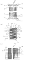
次に、図2及び図3を参照しながら、第1ポート3及び積層された第1伝熱管1の第1冷媒流路1aが連通する構造、並びに、第2ポート4及び積層された第2伝熱管2の第2冷媒流路2aが連通する構造について説明する。図2(a)は、本実施の形態に係る熱交換器10の平面図であり、図2(b)は、図2(a)におけるA-A断面図であり、そして、図2(c)は、同熱交換器10の側面図である。また、図3(a)は、同熱交換器10の蓋8の平面図であり、図3(b)は、同蓋8の正面図であり、そして、図3(c)は、同蓋8の側面図である。また、第1伝熱管1及び第2伝熱管2の積層構造の両側に設けられる蓋8の積層構造は、当該伝熱管の積層構造を中心として180度回転対称の構造を有し、図2(a)におけるA'-A'断面図もまた図2(b)のようになる。
図2(b)及び図3(b)で示されるように、最上段の第1伝熱管1に接合された蓋8の上面及び下面には、第1連通穴3aが貫通して形成されており、第1ポート3は、この蓋8の上面の第1連通穴3aを介して、第1冷媒流路1aに連通している。また、蓋8の下面に形成された第1連通穴3aは、その第1伝熱管1の直下の第2伝熱管2に接合された蓋8の上面に貫通して形成された第1連通穴3bに連通している。ここで、図3で示されるように、第1連通穴3bに連通する部分には封止材8aが存在しており、この封止材8aには第1連通穴3bと連通するように封止材連通穴8bが貫通して形成されている。この封止材連通穴8bは、さらに、蓋8の下面に貫通して形成された第1連通穴3bとも連通している。さらに、この第2伝熱管2の直下の第1伝熱管1には、最上段の第1伝熱管1と同様に、この第1伝熱管1に接合された蓋8の上面及び下面に第1連通穴3aが貫通されており、この第1伝熱管1の直上の第2伝熱管2に接合された蓋8の下面の第1連通穴3bは、このうち第1伝熱管1に接合された蓋8の上面の第1連通穴3aを介してその第1冷媒流路1aに連通している。
すなわち、第1ポート3は、最上段の第1伝熱管1の第1冷媒流路1aに連通しており、さらにこの第1冷媒流路1aは、その直下の第2伝熱管2を介して、さらにその下の第1伝熱管1の第1冷媒流路1aに連通している。以下、同様の構造を取り、第1ポート3及び各第1伝熱管1の第1冷媒流路1aは連通した構造を有し、第2伝熱管2の第2冷媒流路2aとは、蓋8の封止材8aによって遮断された構造を有している。ただし、第1伝熱管1及び第2伝熱管2の積層構造の最下段の第1伝熱管1(図2(b)における下から二番目の伝熱管)に接合された蓋8おいては、その上面のみ第1連通穴3aが形成されている。このような構造によって、2つの第1ポート3のうち一方から流入した冷媒(以下、第1冷媒という)は、積層構造のうち各第1伝熱管1の第1冷媒流路1aを流通して、他方の第1ポート3から流出する。
また、最上段の第1伝熱管1に接合された蓋8の上面には、第2連通穴4aが貫通して形成されており、第2ポート4は、この蓋8の上面の第2連通穴4aに連通している。ここで、図3で示されるように、第2連通穴4aに連通する部分には封止材8aが存在しており、この封止材8aには第2連通穴4aと連通するように封止材連通穴8bが貫通して形成されている。この封止材連通穴8bは、さらに、蓋8の下面に貫通して形成された第2連通穴4aとも連通している。また、この第1伝熱管1の直下の第2伝熱管2に接合された蓋8の上面及び下面には、第2連通穴4bが貫通して形成されており、この第2伝熱管2の直上の第1伝熱管1に接合された蓋8の下面の第2連通穴4aは、このうち第2伝熱管2に接合された蓋8の上面の第2連通穴4bを介して、第2冷媒流路2aに連通している。さらに、第2伝熱管2の下面に形成された第2連通穴4bは、その第2伝熱管2の直下の第1伝熱管1に接合された蓋8の上面に貫通して形成された第2連通穴4aに連通している。ここで、上記と同様に、この第2連通穴4aと連通する部分には封止材8aが存在しており、この封止材8aにはこの第2連通穴4aと連通するように封止材連通穴8bが貫通して形成されている。この封止材連通穴8bは、さらに、蓋8の下面に貫通して形成された第2連通穴4aとも連通している。また、この第1伝熱管1の直下の第2伝熱管2に接合された蓋8の上面及び下面には、第2連通穴4bが貫通して形成されており、この第2伝熱管2の直上の第1伝熱管1に接合された蓋8の下面の第2連通穴4aは、このうち第2伝熱管2に接合された蓋8の上面の第2連通穴4bを介して、第2冷媒流路2aに連通している。
すなわち、第2ポート4は、最上段の第1伝熱管1の直下の第2伝熱管2の第2冷媒流路2aに連通しており、さらにこの第2冷媒流路2aは、その直下の第1伝熱管1を介して、さらにその下の第2伝熱管2の第2冷媒流路2aに連通している。以下、同様の構造を取り、第2ポート4及び各第2伝熱管2の第2冷媒流路2aは連通した構造を有し、第1伝熱管1の第1冷媒流路1aとは、蓋8の封止材8aによって遮断された構造を有している。ただし、第1伝熱管1及び第2伝熱管2の積層構造の最下段の第2伝熱管2(図2(b)における最下段の伝熱管)に接合された蓋8においては、その上面のみ第2連通穴4bが形成されている。このような構造によって、2つの第2ポート4のうち一方から流入した冷媒(以下、第2冷媒という)は、積層構造のうち各第2伝熱管2の第2冷媒流路2aを流通して、他方の第2ポート4から流出する。
なお、図1で示されるように、それぞれ4つの第1伝熱管1及び第2伝熱管2が交互に積層される構造としているが、これに限定されるものではなく、それぞれ4つ以外の個数の第1伝熱管1及び第2伝熱管2が交互に積層される構造としてもよい。
また、積層される第1伝熱管1及び第2伝熱管2の個数は同数に限定されるものではなく、例えば、第1伝熱管1の個数が、第2伝熱管2の個数よりも1つ少なく、又は、1つ多い積層構造としてもよい。
また、図1及び図2で示されるように、第1伝熱管1及び第2伝熱管2が交互に積層される構造としているが、これに限定されるものではなく、必ずしも交互に積層されなくてもよい。
また、図2(b)で示されるように、第1伝熱管1及び第2伝熱管2それぞれに、断面が矩形状の第1冷媒流路1a及び第2冷媒流路2aを形成しているものとしているが、これに限定されるものではなく、例えば、楕円状等のその他の形状としてもよい。
また、図3で示されるように、封止材8aを矩形状としているが、これに限定されるものではなく、封止材連通穴8bを形成することができる範囲で、異なる形状としてもよい。
また、図1及び図2で示されるように、第1伝熱管1及び第2伝熱管2の平面形状は長方形としているが、これに限定されるものではなく、例えば、長方形の四隅をR形状としてもよく、平行四辺形等としてもよく、あるいは、ヒートポンプシステム等に搭載される位置によって形状を適宜変更するものとしてもよい。
また、図2で示されるように、第1伝熱管1に接合された蓋8に形成された第1連通穴3a、第2伝熱管2に接合された蓋8に形成された第1連通穴3b、及び、封止材8aの封止材連通穴8bは、同一径、かつ、積層方向に同心状に形成されているが、これに限定されるものではなく、同一径ではなく、あるいは、積層方向に同心状でないように形成されてもよく、各第1伝熱管1の第1冷媒流路1aが連通されるように形成されるものとすればよい。同様に、第1伝熱管1に接合された蓋8に形成された第2連通穴4a、第2伝熱管2に接合された蓋8に形成された第2連通穴4b、及び、封止材8aの封止材連通穴8bは、同一径、かつ、積層方向に同心状に形成されているが、これに限定されるものではなく、同一径ではなく、あるいは、積層方向に同心状でないように形成されてもよく、各第2伝熱管2の第2冷媒流路2aが連通されるように形成されるものとすればよい。また、上記の各穴は、円形状に限定されるものでもなく、矩形状等のその他の形状で形成されてもよい。
(熱交換器10の製造方法)
図4は、本発明の実施の形態1に係る積層型熱交換器である熱交換器10の要部断面図であり、図5は、同熱交換器10の製造方法を示す図である。
図1及び図2で示される本実施の形態の熱交換器10の第1伝熱管1及び第2伝熱管2は、熱伝導性の良い材質、例えば、アルミ合金、銅又はステンレス等によって構成され、平板をロール成形等で曲げた後、この平板の両端部である継ぎ目を電縫(溶接)して形成したり、円筒をロール成形若しくはプレス成形したり、又は、押し出し成形若しくは引き抜き成形したりすることによって製造される。この、第1伝熱管1及び第2伝熱管2は、図4で示されるように、交互に積層され、互いの当接面において、アルミ-シリコン系等のろう材21によってろう付けされて積層構造が形成される。
なお、第1伝熱管1及び第2伝熱管2は、交互に積層して、互いの当接面においてろう材21によってろう付けした積層構造である伝熱部の製造方法について説明したが、これに限定されるものではない。すなわち、一体押し出し成形、又は、一体引き抜き成形等により成形された一体型の伝熱部としてもよい。
また、蓋8は、熱伝導性の良い材質、例えば、アルミ合金、銅又はステンレス等によって構成され、蓋8と封止材8aとは別部品として構成、又は、鋳造等の一体成型品若しくは切削等の加工品として構成される。また、第1伝熱管1の両端である第1伝熱管端部5、及び、第2伝熱管2の両端である第2伝熱管端部6には、蓋8の蓋穴形状部8cに挿入できるように、第1伝熱管1又は第2伝熱管2の扁平管の断面面積よりも小さくなるように切削して凸形状となるように蓋装着部9aが形成されている。一方、蓋8には、第1伝熱管1又は第2伝熱管2の蓋装着部9aが挿入できるように、蓋装着部9aの断面面積と略同一となるように蓋穴形状部8cの内壁面を切削して凹形状となるように伝熱管装着部9bが形成されている。さらに、図2及び図3において前述した、第1ポート3及び積層された第1伝熱管1の第1冷媒流路1aが連通する構造、並びに、第2ポート4及び積層された第2伝熱管2の第2冷媒流路2aが連通する構造となるように、第1連通穴3a、3b、第2連通穴4a、4b、及び、封止材連通穴8bが貫通して形成される。具体的には、第1伝熱管1に接合される蓋8には、第1連通穴3a及び第2連通穴4a並びに封止材連通穴8bが形成され、第2伝熱管2に接合される蓋8には、第1連通穴3b及び第2連通穴4b並びに封止材連通穴8bが形成される。以上のように形成された蓋8の伝熱管装着部9bに、第1伝熱管1及び第2伝熱管2に形成された蓋装着部9aを挿入して嵌合し、蓋装着部9aと伝熱管装着部9bとの当接面、及び、蓋8と、第1伝熱管端部5及び第2伝熱管端部6との当接面をろう材21によってろう付けして、蓋8が第1伝熱管1及び第2伝熱管2に接合される。
これによって、第1伝熱管端部5及び第2伝熱管端部6から冷媒が漏洩することがない。また、封止材8aが蓋穴形状部8c内に設置されることによって、第1冷媒流路1aと第2冷媒流路2aとは、連通することがなく、第1冷媒流路1aを流通する第1冷媒と、第2冷媒流路2aを流通する第2冷媒とが混合されてしまうこともない。
また、図5(b)で示されるように、第1伝熱管1及び第2伝熱管2の積層構造の最上段の伝熱管である第1伝熱管1に接合された蓋8の上面には、管状の第1ポート3及び第2ポート4が、それぞれ2つずつ、ろう材(図示せず)によってろう付けされて設置される。そして、前述したように、第1ポート3は、すべての第1伝熱管1の第1冷媒流路1aに連通するように構成され、そして、第2ポート4は、すべての第2伝熱管2の第2冷媒流路2aに連通するように構成される。
以上のような方法によって、積層型熱交換器である熱交換器10が構成される。
なお、第1伝熱管1及び第2伝熱管2の蓋装着部9aを凸形状とし、蓋8の伝熱管装着部9bを凹形状としたが、これに限定されるものではない。すなわち、蓋装着部9aとして凹形状を形成し、伝熱管装着部9bとして凸形状として、蓋装着部9aに伝熱管装着部9bを挿入して嵌合させる構成としてもよい。
(熱交換器10の熱交換動作)
本実施の形態に係る積層型熱交換器である熱交換器10は、温熱又は冷熱を利用するヒートポンプシステムに搭載される。例えば、温熱を利用する動作の場合、冷媒回路から流れてきた高温の第1冷媒は、一方の第1ポート3から熱交換器10内に流入して、各第1伝熱管1の第1冷媒流路1aを流通し、他方の第1ポート3から流出する。また、利用側回路から流れてきた第2冷媒は、一方の第2ポート4から熱交換器10内に流入して、各第2伝熱管2の第2冷媒流路2aを流通し、他方の第2ポート4から流出する。このとき、第1冷媒及び第2冷媒は、それぞれ第1伝熱管1の第1冷媒流路1a、及び、第2伝熱管2の第2冷媒流路2aを対向流又は平行流となるように流れて、第1伝熱管1及び第2伝熱管2の壁面を介して、互いに熱交換が実施される。
本実施の形態に係る積層型熱交換器である熱交換器10は、温熱又は冷熱を利用するヒートポンプシステムに搭載される。例えば、温熱を利用する動作の場合、冷媒回路から流れてきた高温の第1冷媒は、一方の第1ポート3から熱交換器10内に流入して、各第1伝熱管1の第1冷媒流路1aを流通し、他方の第1ポート3から流出する。また、利用側回路から流れてきた第2冷媒は、一方の第2ポート4から熱交換器10内に流入して、各第2伝熱管2の第2冷媒流路2aを流通し、他方の第2ポート4から流出する。このとき、第1冷媒及び第2冷媒は、それぞれ第1伝熱管1の第1冷媒流路1a、及び、第2伝熱管2の第2冷媒流路2aを対向流又は平行流となるように流れて、第1伝熱管1及び第2伝熱管2の壁面を介して、互いに熱交換が実施される。
なお、本実施の形態に係る熱交換器10において、第1伝熱管1の第1冷媒流路1aの流路面積、及び、第2伝熱管2の第2冷媒流路2aの流路面積は、必ずしも同一である必要はない。第1冷媒と第2冷媒との間に、比熱若しくは密度等の熱物性値、流量、圧力条件、又は、流体の清浄度等について差がある場合には、第1冷媒流路1aと第2冷媒流路2aとで流路面積を異なるようにしてもよい。例えば、第1冷媒として二酸化炭素又はフロン系の冷媒を用いて、第2冷媒として十分には水質管理されていない水道水等を用いる場合には、熱交換性能を向上するために、あるいは、冷媒流路内面へのスケール付着による圧力損失の増大を抑制するために、冷媒流路面積は、第2冷媒流路2aの流路面積を第1冷媒流路1aの流路面積より大きくするとよい。
(実施の形態1の効果)
特許文献1に記載されている熱交換器は、各伝熱管へ冷媒を分配するヘッダー管によってデッドスペースを有しており、スペース効率を低下させていたが、上記の構成のように、第1ポート3から各第1伝熱管1の第1冷媒流路1aを連通させ、そして、第2ポート4から各第2伝熱管2の第2冷媒流路2aを連通させることによって、ヘッダー管を不要とすることができ、デッドスペースをなくすことができ、熱交換器10全体をコンパクトにすることができる。
特許文献1に記載されている熱交換器は、各伝熱管へ冷媒を分配するヘッダー管によってデッドスペースを有しており、スペース効率を低下させていたが、上記の構成のように、第1ポート3から各第1伝熱管1の第1冷媒流路1aを連通させ、そして、第2ポート4から各第2伝熱管2の第2冷媒流路2aを連通させることによって、ヘッダー管を不要とすることができ、デッドスペースをなくすことができ、熱交換器10全体をコンパクトにすることができる。
また、特許文献1に記載されている熱交換器は、ヘッダー管に接合された伝熱管を曲げ加工する必要があるが、本実施の形態に係る熱交換器10における伝熱管(第1伝熱管1及び第2伝熱管2)については、そのような曲げ加工を実施する必要がなく、蓋8に穴加工を施すのみでよいので、工作性に優れている。
また、第1伝熱管1及び第2伝熱管2を交互に積層することによって、第1冷媒と第2冷媒との熱交換効率を向上させることができる。さらに、第1伝熱管1及び第2伝熱管2を、その冷媒流路の冷媒の流通方向、及び、冷媒流路の幅方向において略同一の長さとすることによって、第1冷媒と第2冷媒との熱交換をさらに効果的に実施することができ、かつ、熱交換器10全体をコンパクトにすることができる。
また、熱交換器10の積層構造の最上段の伝熱管(図1及び図2においては、第1伝熱管1)に接合された蓋8の上面において、2つの第1ポート3及び第2ポート4をそれぞれ、対角となる位置、かつ、伝熱管における冷媒流路の端部である蓋8に備えているので、各第1冷媒流路1a及び各第2冷媒流路2aにおける冷媒が流れる流路長を略最長にすることができ、第1冷媒と第2冷媒との熱交換効率をさらに向上させることができる。
ただし、第1ポート3及び第2ポート4を上記の位置に設置することに限定するものではなく、ヒートポンプシステム等における熱交換器10の搭載位置によって、第1ポート3及び第2ポート4の位置を適宜変更するものとしてもよい。
さらに、図1及び図2で示されるように、それぞれ2つの第1ポート3及び第2ポート4は、熱交換器10の積層構造の最上段の伝熱管に接合された蓋8の上面に設置される構成としているが、これについても限定されるものではない。例えば、2つの第1ポート3のうち一方を積層構造の最上段の伝熱管に接合された蓋8の上面に設置し、他方を積層構造を最下段の伝熱管に接合された蓋8の下面に設置するものとしてもよい。これについては、2つの第2ポート4についても同様である。また、第1ポート3及び第2ポート4を同一面に設置するものとしなくてもよい。例えば、2つの第1ポート3を積層構造の最上段の伝熱管に接合された蓋8の上面に設置し、そして、2つの第2ポート4を積層構造の最下段の伝熱管に接合された蓋8の下面に設置するものとしてもよい。
また、蓋8の蓋穴形状部8c内部に封止材8aを設置し、前述のように、第1連通穴3a、3b、及び、第2連通穴4a、4bを形成することによって、第1冷媒流路1aと第2冷媒流路2aとは、遮断されて連通することがなく、第1冷媒流路1aを流通する第1冷媒と、第2冷媒流路2aを流通する第2冷媒とが混合されることを防止することができる。
さらに、第1伝熱管1及び第2伝熱管2側においては蓋装着部9aを形成し、蓋8側には伝熱管装着部9bを形成し、蓋装着部9aを伝熱管装着部9bに挿入させる構成としたので、蓋8を第1伝熱管1及び第2伝熱管2に接合させるために位置決めしやすくなるという利点がある。
実施の形態2.
図6は、本発明の実施の形態2に係る積層型熱交換器の伝熱管の断面図である。以下、図6を参照しながら、本実施の形態に係る積層型熱交換器の伝熱管の構成について説明する。
図6は、本発明の実施の形態2に係る積層型熱交換器の伝熱管の断面図である。以下、図6を参照しながら、本実施の形態に係る積層型熱交換器の伝熱管の構成について説明する。
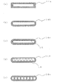
図6(a)~図6(e)で示される伝熱管は何れもその断面が扁平形状を呈している。図6(a)で示される伝熱管14aは、その断面を長方形状とし、その内部の冷媒流路の断面形状も長方形状となっている。また、図6(b)で示される伝熱管14bは、その断面が長手方向における両端部をR形状とし、その内部の冷媒流路の断面形状も同様の形状となっている。この伝熱管14a及び伝熱管14bはいずれも上面及び下面が平面となっており、積層構造とする場合に、互いに密着して接合することができるので、熱交換効率を向上させることができる。
また、図6(c)で示される伝熱管14cは、その断面が長手方向における両端部をR形状とし、その内部の冷媒流路の断面形状も同様の形状となっている。ただし、伝熱管14bとは異なり、その冷媒流路である内壁面には、伝熱管14cの一方の開口部から他方の開口部に向かう方向に、直線状の溝15が複数形成されている。この溝15が形成されることによって、伝熱管14cの内壁面の面積が増大し、隣接した伝熱管に流れる冷媒との熱交換効率を向上させることができる。また、前述したように、溝15の方向を伝熱管14cの一方の開口部から他方の開口部に向かう方向となるようにすることによって、冷媒の圧力損失を低減することができる。また、前述した、伝熱管14a及び伝熱管14bの効果も有することは言うまでもない。
なお、前述したように、伝熱管14cの冷媒流路の内壁面には、一方の開口部から他方の開口部に向かう方向に、溝15が形成されているものとしたが、これに限定されるものではなく、例えば、溝15は、波線状又は斜線状に形成されるものとしてもよい。これによって、伝熱管14cの内壁面の面積が増大し、隣接した伝熱管に流れる冷媒との熱交換効率を向上させることができると共に、冷媒の流れに乱流を発生させることができ、熱交換効率を向上させることができる。
また、図6(d)で示される伝熱管14dは、その断面が長手方向における両端部をR形状とし、その内部の冷媒流路の断面形状も同様の形状となっている。ただし、伝熱管14bとは異なり、その内部である冷媒流路に波形プレート16を挿入している。また、この波形プレート16の波形状における稜線方向が、伝熱管14dの一方の開口部から他方の開口部に向かう方向となるように、波形プレート16を設置している。また、波形プレート16の波形状における各凸部は、伝熱管14dの内壁面に当接している。この波形プレート16を挿入することによって、冷媒流路を流通する冷媒が内壁面に接することに加え、波形プレート16にも接することによって、その波形プレート16を介して内壁面に温熱又は冷熱が伝達するので、伝熱管14cのように内壁面の面積が増大したことによる効果と同様の効果、すなわち、隣接した伝熱管に流れる冷媒との熱交換効率が向上する効果を有する。また、前述した、伝熱管14a及び伝熱管14bの効果も有することは言うまでもない。
そして、図6(e)で示される伝熱管14eは、その断面が長手方向における両端部をR形状とし、その内部の冷媒流路を長手方向に分割した扁平多穴管形状となっている。このように、扁平多穴管形状とすることによって、冷媒の伝熱管の内壁面に接する面積が増大するので、隣接した伝熱管に流れる冷媒との熱交換効率を向上させることができる。また、前述した、伝熱管14a及び伝熱管14bの効果も有することは言うまでもない。
以上の図6で示される伝熱管14a~伝熱管14eのいずれかを、実施の形態1に係る熱交換器10における第1伝熱管1及び第2伝熱管2として適用するものとし、これによって、以下のような効果を得ることができる。
なお、実施の形態1に係る熱交換器10における第1伝熱管1及び第2伝熱管2として適用する場合に、伝熱管14a~伝熱管14eのいずれか一つを適用することに限定するものではなく、組み合わせて適用するものとしてもよい。
なお、実施の形態1に係る熱交換器10における第1伝熱管1及び第2伝熱管2として適用する場合に、伝熱管14a~伝熱管14eのいずれか一つを適用することに限定するものではなく、組み合わせて適用するものとしてもよい。
(実施の形態2の効果)
図6で示される伝熱管14a~伝熱管14eは、いずれも上面及び下面が平面となっており、積層構造とする場合に、互いに密着して接合することができるので、熱交換効率を向上させることができる。
図6で示される伝熱管14a~伝熱管14eは、いずれも上面及び下面が平面となっており、積層構造とする場合に、互いに密着して接合することができるので、熱交換効率を向上させることができる。
また、図6(c)で示されるように、伝熱管14cの冷媒流路の内壁面に溝15が形成されることによって、伝熱管14cの内壁面の面積が増大し、隣接した伝熱管に流れる冷媒との熱交換効率を向上させることができる。また、この溝15の方向を伝熱管14cの一方の開口部から他方の開口部に向かう方向となるようにすることによって、冷媒の圧力損失を低減することができる。また、溝15を波線状又は斜線状に形成されるものとした場合、伝熱管14cの内壁面の面積が増大し、隣接した伝熱管に流れる冷媒との熱交換効率を向上させることができると共に、冷媒の流れに乱流を発生させることができ、熱交換効率を向上させることができる。
また、図6(d)で示されるように、伝熱管14dの内部である冷媒流路に波形プレート16を挿入することによって、冷媒流路を流通する冷媒が内壁面に接することに加え、波形プレート16にも接することによって、その波形プレート16を介して内壁面に温熱又は冷熱が伝達するので、隣接した伝熱管に流れる冷媒との熱交換効率が向上する効果を有する。
さらに、図6(e)で示されるように、扁平多穴管形状とすることによって、冷媒の伝熱管の内壁面に接する面積が増大するので、隣接した伝熱管に流れる冷媒との熱交換効率を向上させることができる。
実施の形態3.
(ヒートポンプシステムの構成)
図7は、本発明の実施の形態3に係る熱交換器の温熱を利用したヒートポンプシステムの構成図である。以下、図7を参照しながら、第1冷媒と第2冷媒との熱交換を実施する積層型熱交換器としての実施の形態1に係る熱交換器10を搭載した構成について説明する。
(ヒートポンプシステムの構成)
図7は、本発明の実施の形態3に係る熱交換器の温熱を利用したヒートポンプシステムの構成図である。以下、図7を参照しながら、第1冷媒と第2冷媒との熱交換を実施する積層型熱交換器としての実施の形態1に係る熱交換器10を搭載した構成について説明する。
図7で示されるように、本実施の形態に係るヒートポンプシステムは、第1冷媒が流通する第1冷媒回路100、第2冷媒が流通する第2冷媒回路101、及び、第1冷媒と第2冷媒との熱交換を実施する熱交換器10を備えた構成となっている。
第1冷媒回路100は、圧縮機31、熱交換器10、膨張弁33及び室外熱交換器34が順に冷媒配管によって接続されて構成されている。また、室外熱交換器34の近傍には、室外熱交換器34に外気を送り、その外気と室外熱交換器34内を流通する第1冷媒との熱交換を実施させるためのファン39が設置されている。この第1冷媒回路100には、第1冷媒として、例えば、R410A、その他のフロン系冷媒、又は、二酸化炭素若しくは炭化水素等の自然冷媒等を用いるものとすればよい。
第2冷媒回路101は、ポンプ36、利用側熱交換器35及び熱交換器10が順に冷媒配管によって接続されて構成されている。このうち、利用側熱交換器35は、ラジエーター又は床暖房ヒーター等として用いられる。また、この第2冷媒回路101には、第2冷媒として、例えば、フロン系冷媒、二酸化炭素若しくは炭化水素等の自然冷媒、又は、水道水、蒸留水若しくはブライン等を用いるものとすればよい。
なお、室外熱交換器34は、本発明の「熱源側熱交換器」に相当する。
(ヒートポンプシステムの動作)
次に、図7を参照しながら、本実施の形態に係るヒートポンプシステムの動作について説明する。第1冷媒回路100において、圧縮機31によって圧縮され吐出された高温高圧状態の第1冷媒は、熱交換器10へ流入する。熱交換器10へ流入した第1冷媒は、熱交換器10内部において、この第1冷媒に対して対向流又は平行流となるように流れる第2冷媒と熱交換を実施し、第2冷媒に対して放熱して、熱交換器10から流出する。熱交換器10から流出した第1冷媒は、膨張弁33に流れ込み、この膨張弁33によって膨張及び減圧され、低温低圧の第1冷媒となる。この低温低圧の第1冷媒は、室外熱交換器34に流入し、ファン39の回転駆動によって送られてくる外気と熱交換を実施し、低温低圧のガス状態の第1冷媒となって、室外熱交換器34から流出する。この室外熱交換器34から流出したガス状態の第1冷媒は、圧縮機31に流入し、再び、圧縮される。
次に、図7を参照しながら、本実施の形態に係るヒートポンプシステムの動作について説明する。第1冷媒回路100において、圧縮機31によって圧縮され吐出された高温高圧状態の第1冷媒は、熱交換器10へ流入する。熱交換器10へ流入した第1冷媒は、熱交換器10内部において、この第1冷媒に対して対向流又は平行流となるように流れる第2冷媒と熱交換を実施し、第2冷媒に対して放熱して、熱交換器10から流出する。熱交換器10から流出した第1冷媒は、膨張弁33に流れ込み、この膨張弁33によって膨張及び減圧され、低温低圧の第1冷媒となる。この低温低圧の第1冷媒は、室外熱交換器34に流入し、ファン39の回転駆動によって送られてくる外気と熱交換を実施し、低温低圧のガス状態の第1冷媒となって、室外熱交換器34から流出する。この室外熱交換器34から流出したガス状態の第1冷媒は、圧縮機31に流入し、再び、圧縮される。
一方、第2冷媒回路101において、熱交換器10に流入した第2冷媒は、熱交換器10内部において、この第2冷媒に対して対向流又は平行流となるように流れる第1冷媒と熱交換を実施し、第1冷媒によって加熱され、熱交換器10から流出する。熱交換器10から流出した第2冷媒は、ポンプ36によって第2冷媒回路101を循環し、利用側熱交換器35へ流入する。利用側熱交換器35へ流入した第2冷媒は、外部に放熱し、利用側熱交換器35から流出する。利用側熱交換器35から流出した第2冷媒は、再び、熱交換器10に流入して加熱される。
ここで、第2冷媒回路101を流通する第2冷媒として、水を使用する場合、熱交換器10における第2伝熱管2、第2伝熱管2に接合された蓋8、及び、第2ポート4を耐食性材で形成する等、熱交換器10において水と接液する部分は水に対する耐食性を有するように構成するのが望ましい。
なお、熱交換器10の伝熱管として、実施の形態2における伝熱管14a~14eを適用したものを利用してもよいのは言うまでもない。
(実施の形態3の効果)
以上の構成のように、第1伝熱管1及び第2伝熱管2の積層構造を有する熱交換器10を搭載することによって、第1冷媒と第2冷媒との熱交換効率を向上させたヒートポンプシステムを得ることができる。
さらに、実施の形態1及び実施の形態2において説明した効果を有するのは言うまでもない。
以上の構成のように、第1伝熱管1及び第2伝熱管2の積層構造を有する熱交換器10を搭載することによって、第1冷媒と第2冷媒との熱交換効率を向上させたヒートポンプシステムを得ることができる。
さらに、実施の形態1及び実施の形態2において説明した効果を有するのは言うまでもない。
なお、本実施の形態に係るヒートポンプシステムは、図7で示される構成に限定されるものではなく、例えば、以下の図8~図10で示されるヒートポンプシステムの構成としてもよい。
まず、図8は、本実施の形態に係るヒートポンプシステムの別形態の構成図であり、図7で示されるヒートポンプシステムと同様に熱交換器の温熱を利用するものである。
図8で示されるヒートポンプシステムは、図7で示されるヒートポンプシステムにおける利用側熱交換器35をタンク38内に設置したものであり、その他の構成は、図7で示されるヒートポンプシステムと同様である。熱交換器10において加熱された第2冷媒が、利用側熱交換器35を流通することによって、タンク38内の水を加熱して取水することができる構成となっている。
図8で示されるヒートポンプシステムは、図7で示されるヒートポンプシステムにおける利用側熱交換器35をタンク38内に設置したものであり、その他の構成は、図7で示されるヒートポンプシステムと同様である。熱交換器10において加熱された第2冷媒が、利用側熱交換器35を流通することによって、タンク38内の水を加熱して取水することができる構成となっている。
この図8で示されるヒートポンプシステム、及び、前述した図7で示されるヒートポンプシステムのように、熱交換器10の温熱を利用して、利用側熱交換器35を暖房動作又は給湯動作に適用することによって、従来のボイラーを熱源とした暖房又は給湯システムと比較して省エネ効果を向上させることができる。
また、図9は、本実施の形態に係るヒートポンプシステムの別形態の構成図であり、熱交換器の冷熱を利用するものである。
図9で示されるヒートポンプシステムは、図7で示されるヒートポンプシステムにおいて、圧縮機31の吸入口と吐出口とを逆にし、第1冷媒回路100における冷媒の流通方向を逆方向となるように構成したものである。また、利用側熱交換器35は、冷房システムを構成するために、空気熱交換器又は冷水パネルとして用いられる。その他の構成は、図7で示されるヒートポンプシステムと同様である。
図9で示されるヒートポンプシステムは、図7で示されるヒートポンプシステムにおいて、圧縮機31の吸入口と吐出口とを逆にし、第1冷媒回路100における冷媒の流通方向を逆方向となるように構成したものである。また、利用側熱交換器35は、冷房システムを構成するために、空気熱交換器又は冷水パネルとして用いられる。その他の構成は、図7で示されるヒートポンプシステムと同様である。
この図9で示されるヒートポンプシステムにおいては、まず、第1冷媒回路100において、圧縮機31によって圧縮され吐出された高温高圧状態の第1冷媒が、室外熱交換器34へ流入する。室外熱交換器34へ流入した第1冷媒は、ファン39の回転駆動によって送られてくる外気と熱交換を実施し、外気に対して放熱し、室外熱交換器34から流出する。室外熱交換器34から流出した第1冷媒は、膨張弁33に流れ込み、この膨張弁33によって膨張及び減圧され、低温低圧の第1冷媒となる。この低温低圧の第1冷媒は、熱交換器10へ流入し、熱交換器10内部において、この第1冷媒に対して対向流又は平行流となるように流れる第2冷媒と熱交換を実施し、第2冷媒から吸熱して、低温低圧のガス状態の第1冷媒となって、熱交換器10から流出する。この熱交換器10から流出したガス状態の第1冷媒は、圧縮機31に流入し、再び、圧縮される。
そして、第2冷媒回路101において、熱交換器10に流入した第2冷媒は、熱交換器10内部において、この第2冷媒に対して対向流又は平行流となるように流れる第1冷媒と熱交換を実施し、第1冷媒によって冷却され、熱交換器10から流出する。熱交換器10から流出した第2冷媒は、ポンプ36によって第2冷媒回路101を循環し、利用側熱交換器35へ流入する。利用側熱交換器35へ流入した第2冷媒は、外気等を冷却し、利用側熱交換器35から流出する。利用側熱交換器35から流出した第2冷媒は、再び、熱交換器10に流入して冷却される。
なお、この図9で示されるヒートポンプシステムに対して、図8で示されるヒートポンプシステムと同様に、タンク38を設置し、このタンク38に利用側熱交換器35を設置する構成としてもよい。この場合、利用側熱交換器35によってタンク38内の水を冷却して取水する構成とすることができる。
そして、図10は、本実施の形態に係るヒートポンプシステムの別形態の構成図であり、熱交換器による温熱又は冷熱を利用するものである。
図10で示されるヒートポンプシステムは、図7で示されるヒートポンプシステムにおける第1冷媒回路100に四方弁32を追加したものである。具体的には、第1冷媒回路100は、圧縮機31、四方弁32、熱交換器10、膨張弁33、室外熱交換器34、四方弁32、そして、圧縮機31という順に冷媒配管によって接続されたものである。その他の構成は、図9で示されるヒートポンプシステムと同様である。このような構成において、四方弁32の流路を切り替えることによって、図7で示されるヒートポンプシステムのように熱交換器10の温熱を利用し、あるいは、図9で示されるヒートポンプシステムのように熱交換器10の冷熱を利用することができる。
図10で示されるヒートポンプシステムは、図7で示されるヒートポンプシステムにおける第1冷媒回路100に四方弁32を追加したものである。具体的には、第1冷媒回路100は、圧縮機31、四方弁32、熱交換器10、膨張弁33、室外熱交換器34、四方弁32、そして、圧縮機31という順に冷媒配管によって接続されたものである。その他の構成は、図9で示されるヒートポンプシステムと同様である。このような構成において、四方弁32の流路を切り替えることによって、図7で示されるヒートポンプシステムのように熱交換器10の温熱を利用し、あるいは、図9で示されるヒートポンプシステムのように熱交換器10の冷熱を利用することができる。
なお、この図10で示されるヒートポンプシステムに対して、図8で示されるヒートポンプシステムと同様に、タンク38を設置し、このタンク38に利用側熱交換器35を設置する構成としてもよい。この場合、四方弁32の流路を切り替えることによって、熱交換器10において加熱された第2冷媒を利用側熱交換器35に流通させてタンク38内の水を加熱して取水することができる構成とし、あるいは、熱交換器10において冷却された第2冷媒を利用側熱交換器35に流通させてタンク38内の水を冷却して取水することができる構成とすることができる。
1 第1伝熱管、1a 第1冷媒流路、2 第2伝熱管、2a 第2冷媒流路、3 第1ポート、3a、3b 第1連通穴、4 第2ポート、4a、4b 第2連通穴、5 第1伝熱管端部、6 第2伝熱管端部、8 蓋、8a 封止材、8b 封止材連通穴、8c 蓋穴形状部、9a 蓋装着部、9b 伝熱管装着部、10 熱交換器、14a~14e 伝熱管、15 溝、16 波形プレート、21 ろう材、31 圧縮機、32 四方弁、33 膨張弁、34 室外熱交換器、35 利用側熱交換器、36 ポンプ、38 タンク、39 ファン、100 第1冷媒回路、101 第2冷媒回路。
Claims (11)
- 扁平形状を有し、第1冷媒がその内部の第1冷媒流路を流通する複数の第1伝熱管と、 扁平形状を有し、前記第1伝熱管と共に積層され、前記第1冷媒と温度が異なる第2冷媒がその内部の第2冷媒流路を流通する複数の第2伝熱管と、
前記各第1伝熱管の前記第1冷媒流路、及び、前記各第2伝熱管の前記第2冷媒流路の冷媒の流通方向の両端部に形成された開口部をそれぞれ閉塞するように、前記各第1伝熱管及び前記各第2伝熱管に接合かつ積層された閉塞手段と、
前記各第1伝熱管に接合された前記閉塞手段及び前記各第2伝熱管に接合された前記閉塞手段において、前記各第1冷媒流路を互いに連通させ、かつ、前記各第1伝熱管及び前記各第2伝熱管の積層構造における積層方向の両端に位置する前記第1伝熱管又は前記第2伝熱管である2つの最外伝熱管のうちいずれか一方の該最外伝熱管に接合された前記閉塞手段において前記各第1冷媒流路と外部とを連通させるように、貫通して形成された第1連通穴と、
前記各第1伝熱管に接合された前記閉塞手段及び前記各第2伝熱管に接合された前記閉塞手段において、前記各第2冷媒流路を互いに連通させ、かつ、2つの前記最外伝熱管のうちいずれか一方の該最外伝熱管に接合された前記閉塞手段において前記各第2冷媒流路と外部とを連通させるように、貫通して形成された第2連通穴と、
前記各第2伝熱管に接合された前記閉塞手段に形成された前記第1連通穴が、前記第2冷媒流路に連通しないように遮断する第1遮断手段と、
前記各第1伝熱管に接合された前記閉塞手段に形成された前記第2連通穴が、前記第1冷媒流路に連通しないように遮断する第2遮断手段と、
を備え、
前記第1連通穴は、2組形成され、
前記第2連通穴は、2組形成され、
前記最外伝熱管に接合された前記閉塞手段に形成され、前記各第1冷媒流路と外部とを連通させる2つの前記第1連通穴は、それぞれ前記第1冷媒の流入口及び流出口として機能し、
前記最外伝熱管に接合された前記閉塞手段に形成され、前記各第2冷媒流路と外部とを連通させる2つの前記第2連通穴は、それぞれ前記第2冷媒の流入口及び流出口として機能する
ことを特徴とする積層型熱交換器。 - 前記各第1伝熱管及び前記各第2伝熱管は、交互に当接して積層されて、前記積層構造が構成された
ことを特徴とする請求項1記載の積層型熱交換器。 - 前記積層構造は、一体型に成形された
ことを特徴とする請求項1又は請求項2記載の積層型熱交換器。 - 前記閉塞手段は、前記第1冷媒流路又は前記第2冷媒流路と連通する穴形状部、及び、該穴形状部内に設けられ、連通穴が貫通して形成された封止材を有し、
前記第1遮断手段は、前記第2伝熱管に接合された前記閉塞手段の前記封止材によって構成され、該各封止材の前記連通穴は、前記第1連通穴と連通し、
前記第2遮断手段は、前記第1伝熱管に接合された前記閉塞手段の前記封止材によって構成され、該各封止材の前記連通穴は、前記第2連通穴と連通した
ことを特徴とする請求項1~請求項3のいずれか一項に記載の積層型熱交換器。 - 前記第1伝熱管及び前記第2伝熱管の両端部、又は、前記閉塞手段の前記穴形状部の開口部のいずれか一方を凸形状となるように形成し、他方を凹形状となるように形成し、前記凸形状部分を前記凹形状部分に挿入して嵌合させることによって、前記閉塞手段がそれぞれ前記第1伝熱管及び前記第2伝熱管に接合された
ことを特徴とする請求項4記載の積層型熱交換器。 - 2組の前記第1連通穴及び2組の前記第2連通穴は、前記積層構造の積層方向から見て、それぞれ、前記第1伝熱管又は前記第2伝熱管、及び、それに接合された前記閉塞手段で構成された平面の対角となる位置に形成された
ことを特徴とする請求項1~請求項5のいずれか一項に記載の積層型熱交換器。 - 前記各第1伝熱管及び前記各第2伝熱管の断面形状が、長方形状、扁平多穴管形状、又は、断面の長手方向における両端部をR形状としたもののうち少なくともいずれかである ことを特徴とする請求項1~請求項6のいずれか一項に記載の積層型熱交換器。
- 複数の前記第1伝熱管のうち少なくともいずれかの前記第1冷媒流路、及び/又は、複数の前記第2伝熱管のうち少なくともいずれかの前記第2冷媒流路は、その内壁面に複数の溝を有した
ことを特徴とする請求項1~請求項7のいずれか一項に記載の積層型熱交換器。 - 複数の前記第1伝熱管のうち少なくともいずれかの前記第1冷媒流路、及び/又は、複数の前記第2伝熱管のうち少なくともいずれかの前記第2冷媒流路には、波形プレートが設置され、
該波形プレートは、その波形状の稜線方向が前記第1冷媒流路又は前記第2冷媒流路の冷媒の流通方向と同一であり、前記波形状における各凸部が前記第1冷媒流路又は前記第2冷媒流路の内壁面に当接した
ことを特徴とする請求項1~請求項7のいずれか一項に記載の積層型熱交換器。 - 圧縮機、請求項1~請求項9のいずれか一項に記載の積層型熱交換器、膨張装置及び熱源側熱交換器が冷媒配管によって接続された冷媒回路によって構成され、前記第1冷媒が流通する第1冷媒回路と、
ポンプ、利用側熱交換器及び前記積層型熱交換器が冷媒配管によって接続された冷媒回路によって構成され、前記第2冷媒が流通する第2冷媒回路と、
を備えたヒートポンプシステム。 - 複数の前記第1伝熱管と複数の前記第2伝熱管を交互にろう付けして前記積層構造を形成する工程と、
前記各第1伝熱管の前記第1冷媒流路、及び、前記各第2伝熱管の前記第2冷媒流路の冷媒の流通方向の両端部に形成された前記開口部を閉塞する前記閉塞手段を接合する工程と、
前記閉塞手段に、2組の前記第1連通穴、及び、2組の前記第2連通穴を貫通して形成する工程と、
を有した
ことを特徴とする請求項1~請求項10のいずれか一項に記載の積層型熱交換器の製造方法。
Priority Applications (1)
| Application Number | Priority Date | Filing Date | Title |
|---|---|---|---|
| JP2013556041A JP5661205B2 (ja) | 2012-01-30 | 2012-06-15 | 積層型熱交換器及びそれを搭載したヒートポンプシステム、並びに積層型熱交換器の製造方法 |
Applications Claiming Priority (2)
| Application Number | Priority Date | Filing Date | Title |
|---|---|---|---|
| JP2012017126 | 2012-01-30 | ||
| JP2012-017126 | 2012-01-30 |
Publications (1)
| Publication Number | Publication Date |
|---|---|
| WO2013114474A1 true WO2013114474A1 (ja) | 2013-08-08 |
Family
ID=48904564
Family Applications (1)
| Application Number | Title | Priority Date | Filing Date |
|---|---|---|---|
| PCT/JP2012/003943 WO2013114474A1 (ja) | 2012-01-30 | 2012-06-15 | 積層型熱交換器及びそれを搭載したヒートポンプシステム、並びに積層型熱交換器の製造方法 |
Country Status (2)
| Country | Link |
|---|---|
| JP (1) | JP5661205B2 (ja) |
| WO (1) | WO2013114474A1 (ja) |
Cited By (5)
| Publication number | Priority date | Publication date | Assignee | Title |
|---|---|---|---|---|
| CN109751900A (zh) * | 2017-11-03 | 2019-05-14 | 斗山重工业建设有限公司 | 包括一体型结构的印刷电路板式热交换器 |
| KR102105026B1 (ko) * | 2019-12-09 | 2020-05-29 | 오충록 | 대형 공간용 열회수 환기장치 |
| WO2021171637A1 (ja) * | 2020-02-25 | 2021-09-02 | 日本軽金属株式会社 | 熱交換器の製造方法 |
| WO2021171635A1 (ja) * | 2020-02-25 | 2021-09-02 | 日本軽金属株式会社 | 熱交換器の製造方法 |
| WO2021171636A1 (ja) * | 2020-02-25 | 2021-09-02 | 日本軽金属株式会社 | 熱交換器の製造方法 |
Citations (7)
| Publication number | Priority date | Publication date | Assignee | Title |
|---|---|---|---|---|
| JP2004177006A (ja) * | 2002-11-27 | 2004-06-24 | Japan Climate Systems Corp | 内部熱交換器 |
| JP2004205056A (ja) * | 2002-12-20 | 2004-07-22 | Toyo Radiator Co Ltd | 熱併給兼放熱用熱交換器 |
| JP2006329537A (ja) * | 2005-05-26 | 2006-12-07 | Sanden Corp | 熱交換器 |
| WO2007122685A1 (ja) * | 2006-04-14 | 2007-11-01 | Mitsubishi Denki Kabushiki Kaisha | 熱交換器及び冷凍空調装置 |
| WO2007123041A1 (ja) * | 2006-04-19 | 2007-11-01 | Calsonic Kansei Corporation | 内部熱交換器 |
| JP2007333304A (ja) * | 2006-06-15 | 2007-12-27 | Valeo Thermal Systems Japan Corp | 熱交換器 |
| EP2273224A1 (fr) * | 2009-06-02 | 2011-01-12 | Valeo Systèmes Thermiques | Unité d'échange thermique et échangeur thermique correspondant, procédé de réalisation d'une unité d'échange thermique |
Family Cites Families (1)
| Publication number | Priority date | Publication date | Assignee | Title |
|---|---|---|---|---|
| DE202009015586U1 (de) * | 2009-11-12 | 2011-03-24 | Autokühler GmbH & Co. KG | Wärmeaustauschernetz |
-
2012
- 2012-06-15 WO PCT/JP2012/003943 patent/WO2013114474A1/ja active Application Filing
- 2012-06-15 JP JP2013556041A patent/JP5661205B2/ja active Active
Patent Citations (7)
| Publication number | Priority date | Publication date | Assignee | Title |
|---|---|---|---|---|
| JP2004177006A (ja) * | 2002-11-27 | 2004-06-24 | Japan Climate Systems Corp | 内部熱交換器 |
| JP2004205056A (ja) * | 2002-12-20 | 2004-07-22 | Toyo Radiator Co Ltd | 熱併給兼放熱用熱交換器 |
| JP2006329537A (ja) * | 2005-05-26 | 2006-12-07 | Sanden Corp | 熱交換器 |
| WO2007122685A1 (ja) * | 2006-04-14 | 2007-11-01 | Mitsubishi Denki Kabushiki Kaisha | 熱交換器及び冷凍空調装置 |
| WO2007123041A1 (ja) * | 2006-04-19 | 2007-11-01 | Calsonic Kansei Corporation | 内部熱交換器 |
| JP2007333304A (ja) * | 2006-06-15 | 2007-12-27 | Valeo Thermal Systems Japan Corp | 熱交換器 |
| EP2273224A1 (fr) * | 2009-06-02 | 2011-01-12 | Valeo Systèmes Thermiques | Unité d'échange thermique et échangeur thermique correspondant, procédé de réalisation d'une unité d'échange thermique |
Cited By (5)
| Publication number | Priority date | Publication date | Assignee | Title |
|---|---|---|---|---|
| CN109751900A (zh) * | 2017-11-03 | 2019-05-14 | 斗山重工业建设有限公司 | 包括一体型结构的印刷电路板式热交换器 |
| KR102105026B1 (ko) * | 2019-12-09 | 2020-05-29 | 오충록 | 대형 공간용 열회수 환기장치 |
| WO2021171637A1 (ja) * | 2020-02-25 | 2021-09-02 | 日本軽金属株式会社 | 熱交換器の製造方法 |
| WO2021171635A1 (ja) * | 2020-02-25 | 2021-09-02 | 日本軽金属株式会社 | 熱交換器の製造方法 |
| WO2021171636A1 (ja) * | 2020-02-25 | 2021-09-02 | 日本軽金属株式会社 | 熱交換器の製造方法 |
Also Published As
| Publication number | Publication date |
|---|---|
| JPWO2013114474A1 (ja) | 2015-05-11 |
| JP5661205B2 (ja) | 2015-01-28 |
Similar Documents
| Publication | Publication Date | Title |
|---|---|---|
| JP6641544B1 (ja) | プレート式熱交換器及びそれを備えたヒートポンプ装置 | |
| US10161687B2 (en) | Plate heat exchanger and heat pump outdoor unit | |
| JP6615423B1 (ja) | プレート式熱交換器、プレート式熱交換器を備えたヒートポンプ装置、及び、ヒートポンプ装置を備えたヒートポンプ式冷暖房給湯システム | |
| CN111837010B (zh) | 板式热交换器、热泵装置以及热泵式制冷制热供热水系统 | |
| WO2013183629A1 (ja) | プレート式熱交換器及びそれを備えた冷凍サイクル装置 | |
| JP5206830B2 (ja) | 熱交換器 | |
| JP5661205B2 (ja) | 積層型熱交換器及びそれを搭載したヒートポンプシステム、並びに積層型熱交換器の製造方法 | |
| WO2020100276A1 (ja) | プレート式熱交換器、ヒートポンプ装置およびヒートポンプ式冷暖房給湯システム | |
| JP5496369B2 (ja) | 積層型熱交換器及びそれを搭載したヒートポンプシステム | |
| JP4122670B2 (ja) | 熱交換器 | |
| JP2010121925A (ja) | 熱交換器 | |
| WO2014061105A1 (ja) | プレート式熱交換器及びこのプレート式熱交換器を備えた冷凍サイクル装置 | |
| JP5744316B2 (ja) | 熱交換器及びこの熱交換器を備えたヒートポンプシステム | |
| JP2016183811A (ja) | マイクロ流路熱交換器 | |
| JP5046748B2 (ja) | 給湯システムのガスクーラ | |
| WO2018088169A1 (ja) | 熱交換器 | |
| JP6601380B2 (ja) | 熱交換器および空気調和装置 | |
| KR100925097B1 (ko) | 수랭식 열교환기 | |
| JP5940152B2 (ja) | プレート式熱交換器及びそれを備えた冷凍サイクル装置 | |
| JP2007010299A (ja) | 熱交換器および給湯装置 | |
| JP6146966B2 (ja) | 冷温水熱源機 | |
| JP2007303762A (ja) | 冷暖房システム | |
| JP2015068621A (ja) | 水熱交換器 |
Legal Events
| Date | Code | Title | Description |
|---|---|---|---|
| 121 | Ep: the epo has been informed by wipo that ep was designated in this application |
Ref document number: 12867558 Country of ref document: EP Kind code of ref document: A1 |
|
| ENP | Entry into the national phase |
Ref document number: 2013556041 Country of ref document: JP Kind code of ref document: A |
|
| NENP | Non-entry into the national phase |
Ref country code: DE |
|
| 122 | Ep: pct application non-entry in european phase |
Ref document number: 12867558 Country of ref document: EP Kind code of ref document: A1 |