EP2017543A1 - Innenraumeinheit für klimaanlage - Google Patents
Innenraumeinheit für klimaanlage Download PDFInfo
- Publication number
- EP2017543A1 EP2017543A1 EP07742538A EP07742538A EP2017543A1 EP 2017543 A1 EP2017543 A1 EP 2017543A1 EP 07742538 A EP07742538 A EP 07742538A EP 07742538 A EP07742538 A EP 07742538A EP 2017543 A1 EP2017543 A1 EP 2017543A1
- Authority
- EP
- European Patent Office
- Prior art keywords
- panel
- corner
- swing member
- screw
- opening
- Prior art date
- Legal status (The legal status is an assumption and is not a legal conclusion. Google has not performed a legal analysis and makes no representation as to the accuracy of the status listed.)
- Granted
Links
- 230000007246 mechanism Effects 0.000 claims abstract description 25
- 230000033001 locomotion Effects 0.000 claims description 7
- 239000002184 metal Substances 0.000 description 27
- 239000000725 suspension Substances 0.000 description 12
- 238000013461 design Methods 0.000 description 6
- 238000003780 insertion Methods 0.000 description 6
- 230000037431 insertion Effects 0.000 description 6
- 210000002105 tongue Anatomy 0.000 description 4
- 238000007796 conventional method Methods 0.000 description 3
- 238000009434 installation Methods 0.000 description 3
- 239000012212 insulator Substances 0.000 description 3
- 238000012423 maintenance Methods 0.000 description 3
- NJPPVKZQTLUDBO-UHFFFAOYSA-N novaluron Chemical compound C1=C(Cl)C(OC(F)(F)C(OC(F)(F)F)F)=CC=C1NC(=O)NC(=O)C1=C(F)C=CC=C1F NJPPVKZQTLUDBO-UHFFFAOYSA-N 0.000 description 3
- 230000009471 action Effects 0.000 description 2
- 230000007423 decrease Effects 0.000 description 2
- 239000000463 material Substances 0.000 description 2
- 238000000034 method Methods 0.000 description 2
- 238000000926 separation method Methods 0.000 description 2
- 229920003002 synthetic resin Polymers 0.000 description 2
- 239000000057 synthetic resin Substances 0.000 description 2
- XLYOFNOQVPJJNP-UHFFFAOYSA-N water Substances O XLYOFNOQVPJJNP-UHFFFAOYSA-N 0.000 description 2
- 238000007664 blowing Methods 0.000 description 1
- 210000000078 claw Anatomy 0.000 description 1
- 238000010586 diagram Methods 0.000 description 1
- 239000000428 dust Substances 0.000 description 1
- 230000000694 effects Effects 0.000 description 1
- 239000006260 foam Substances 0.000 description 1
- 230000006872 improvement Effects 0.000 description 1
- 238000009413 insulation Methods 0.000 description 1
- 239000012774 insulation material Substances 0.000 description 1
- 230000008569 process Effects 0.000 description 1
- 230000002787 reinforcement Effects 0.000 description 1
- 239000000758 substrate Substances 0.000 description 1
- 238000003466 welding Methods 0.000 description 1
Images


Classifications
-
- F—MECHANICAL ENGINEERING; LIGHTING; HEATING; WEAPONS; BLASTING
- F24—HEATING; RANGES; VENTILATING
- F24F—AIR-CONDITIONING; AIR-HUMIDIFICATION; VENTILATION; USE OF AIR CURRENTS FOR SCREENING
- F24F13/00—Details common to, or for air-conditioning, air-humidification, ventilation or use of air currents for screening
- F24F13/20—Casings or covers
-
- F—MECHANICAL ENGINEERING; LIGHTING; HEATING; WEAPONS; BLASTING
- F24—HEATING; RANGES; VENTILATING
- F24F—AIR-CONDITIONING; AIR-HUMIDIFICATION; VENTILATION; USE OF AIR CURRENTS FOR SCREENING
- F24F1/00—Room units for air-conditioning, e.g. separate or self-contained units or units receiving primary air from a central station
- F24F1/0007—Indoor units, e.g. fan coil units
- F24F1/0011—Indoor units, e.g. fan coil units characterised by air outlets
- F24F1/0014—Indoor units, e.g. fan coil units characterised by air outlets having two or more outlet openings
-
- F—MECHANICAL ENGINEERING; LIGHTING; HEATING; WEAPONS; BLASTING
- F24—HEATING; RANGES; VENTILATING
- F24F—AIR-CONDITIONING; AIR-HUMIDIFICATION; VENTILATION; USE OF AIR CURRENTS FOR SCREENING
- F24F1/00—Room units for air-conditioning, e.g. separate or self-contained units or units receiving primary air from a central station
- F24F1/0007—Indoor units, e.g. fan coil units
- F24F1/0043—Indoor units, e.g. fan coil units characterised by mounting arrangements
- F24F1/0047—Indoor units, e.g. fan coil units characterised by mounting arrangements mounted in the ceiling or at the ceiling
-
- F—MECHANICAL ENGINEERING; LIGHTING; HEATING; WEAPONS; BLASTING
- F24—HEATING; RANGES; VENTILATING
- F24F—AIR-CONDITIONING; AIR-HUMIDIFICATION; VENTILATION; USE OF AIR CURRENTS FOR SCREENING
- F24F1/00—Room units for air-conditioning, e.g. separate or self-contained units or units receiving primary air from a central station
- F24F1/0007—Indoor units, e.g. fan coil units
- F24F1/0059—Indoor units, e.g. fan coil units characterised by heat exchangers
- F24F1/0063—Indoor units, e.g. fan coil units characterised by heat exchangers by the mounting or arrangement of the heat exchangers
-
- F—MECHANICAL ENGINEERING; LIGHTING; HEATING; WEAPONS; BLASTING
- F24—HEATING; RANGES; VENTILATING
- F24F—AIR-CONDITIONING; AIR-HUMIDIFICATION; VENTILATION; USE OF AIR CURRENTS FOR SCREENING
- F24F1/00—Room units for air-conditioning, e.g. separate or self-contained units or units receiving primary air from a central station
- F24F1/0007—Indoor units, e.g. fan coil units
- F24F1/0011—Indoor units, e.g. fan coil units characterised by air outlets
-
- F—MECHANICAL ENGINEERING; LIGHTING; HEATING; WEAPONS; BLASTING
- F24—HEATING; RANGES; VENTILATING
- F24F—AIR-CONDITIONING; AIR-HUMIDIFICATION; VENTILATION; USE OF AIR CURRENTS FOR SCREENING
- F24F13/00—Details common to, or for air-conditioning, air-humidification, ventilation or use of air currents for screening
- F24F13/02—Ducting arrangements
- F24F13/06—Outlets for directing or distributing air into rooms or spaces, e.g. ceiling air diffuser
- F24F2013/0616—Outlets that have intake openings
Definitions
- the present invention relates to an indoor unit for, for example, a ceiling-embedded type air conditioner, and more particularly to an improvement in a fitting/removal structure for corner panels that are provided in the four corners of a dress panel.
- an indoor unit body includes: a casing whose bottom is substantially completely open and whose top and sides are formed from sheet metal, and a heat insulation material fitted on the inner surface of the casing. Disposed in the main body of the indoor unit are a heat exchanger, a blower, a drain pan, an electronic component box, etc.
- An opening at the bottom of the indoor unit body is covered with a dress panel that has a blower opening and a suction opening.
- This dress panel has a rectangular panel body. Provided in the four corners of the panel body are openings, in which corner panels are fitted so that the openings are freely opened or closed. These openings allow the insertion of a tool required to adjust the height of the indoor unit body.
- suspension bolts are attached to a beam forming a space between the roof and the ceiling
- suspension metal fittings attached to the casing engage with nuts screwed on the suspension bolts, and thereby the indoor unit is suspended.
- a tool such as a socket wrench is inserted to access the suspension bolt through each of the openings, thereby allowing adjustment of the nuts, and hence adjustment of the indoor unit height without removing the dress panel.
- an indoor unit for an air conditioner disclosed in Jpn. Pat. Appln. KOKAI Publication No. 2004-85002 has proposed the technique described below.
- the corners of corner panels are provided with tongues with screw holes therein.
- Screw fixing parts are provided near a suction opening on a panel body.
- the corners of the corner panels and corresponding openings must be located to apposition closer to the corresponding corners of the suction opening. This increases the proportion of the areas of the corner panels to the area of the dress panel, leading to limit on design and insufficient area for blower openings formed between the corner panels.
- corner panels can be fitted or removed by their being slid, the fitting or removal of them may not be permitted where an obstacle such as a fluorescent fixture is located in the direction of sliding. Moreover, such an obstacle may not allow even installation of the indoor unit of air conditioner.
- the present invention has been made in view of the problems discussed above, and it is therefore an object of the present invention to provide an indoor unit for an air conditioner, designed so as to increase freedom of design and allow fitting or removal of corner panels irrespective of the installation location of the unit.
- an indoor unit for an air conditioner comprises: an indoor unit body which has an opening at its bottom surface and accommodates therein a heat exchanger, a drain pan, a blower, and the like; and a dress panel which covers the opening at the bottom of the indoor unit body and is exposed to the inside of a room, wherein the dress panel comprises: a rectangular panel body having a suction opening in its center and blower openings provided on all sides of the suction opening; an opening provided in each corner of the panel body; a corner panel fitted in the opening so as to be freely removable; and a corner panel fitting/removal mechanism which fits/removes the corner panel to/from the opening of the panel body, and the corner panel fitting/removal mechanism comprises: a swing member attached to the panel body so as to be freely swingable around its middle, and having a hooking pawl at one end and an operating screw hole at the other end; an operation screw screwed into the operating screw hole in the swing member, used to
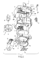
- FIG. 1 is a perspective view showing from below an indoor unit 1 for a ceiling-embedded type air conditioner according to an embodiment of the present invention.
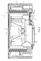
- FIGS. 2 and 3 are an exploded perspective view and a sectional view, respectively, of an indoor unit body 2.
- the indoor unit 1 for the air conditioner includes the indoor unit body 2 inserted in a mounting opening (which has been provided in a ceiling panel from the inside of a room, then suspended and fixed between the roof and the ceiling with suspension bolts or the like.
- the indoor unit 1 also includes a dress panel 3 attached to the under surface of the indoor unit body 2 and exposed to the inside of the room from the ceiling panel.
- the indoor unit body 2 has a casing 4 whose bottom is completely open and whose top and sides are formed from a sheet metal produced from a thin metal plate.
- a heat insulator 5 molded from styrene-foam or suchlike material is attached to the internal circumferential surface of the casing 4.
- the indoor unit body 2 has a heat insulation structure.
- An indoor heat exchanger 7 having a frame form that is quadrangular as viewed from above is mounted around the blower 6.
- a pair of heat exchanger parts in an L-shape as viewed from above may be used as the indoor heat exchanger 7.
- a drain pump 9 is attached to a corner of the indoor unit body 2.
- This dress panel is molded from, for example, a synthetic resin, and finished beautifully.
- the dress panel 3 is exposed to the inside of the room from the ceiling pane and seals a gap between the periphery of the indoor unit body 2 and the mounting opening of the ceiling plate.
- the blower 6 includes: a fan motor M fixed to the upper surface of the casing 4 by use of a suitable means, and a fan F attached to the rotating shaft of the fan motor M.
- the fan F is of a multi-vane type fan that draws air toward the rotating shaft as it rotates and sends out a current of air in a circumferential direction.
- the indoor heat exchanger 7 is disposed opposite the circumferential direction, i.e., blowing direction, of the fan F.
- the lower end of the indoor heat exchanger 7 is inserted in a quadrangular frame-shaped drain pan 10 in the casing 4, thus receiving drain water produced as a result of heat exchange by the indoor heat exchanger 7.
- the drain pump 9 is immersed in the drain water in the drain pan 10.
- the bell mouth 12 Disposed between the dress panel 3 and the blower fan F is a bell mouth 12 such that the drain pan 10 surrounds the sides of the bell mouth 12.
- the bell mouth 12 includes: a horn-shaped converging section 12a that has a small diameter on the blower fan F side and a large diameter on the dress panel 3 side; a flat part 12b formed integrally with the large-diameter side of the converging section 12a; and a sideways slit 12c adjacent to one side of the flat part 12b.
- This electronic component box 13 includes: a box body 14 that is opened at the bottom surface and accommodates a control substrate on which electronic components for control are mounted; and a lid plate 15 that closes the opening at the bottom surface of the box body 14 such that it may be freely opened or closed. Both of the box body 14 and lid plate 15 are made from sheet metal produced from a thin metal plate.
- a fan guard 16 is attached to the large-diameter side of the converging section 12a of the bell mouth 12.
- the fan guard 16 ensures the safety of maintenance workers by preventing hands from directly touching the fan F of the blower 6 even when the dress panel 3 is removed for maintenance.
- the dress panel 3 has a panel body 3A of a rectangular outer shape. Provided in a central part of the panel body 3A is a rectangular suction opening 17.
- the suction opening 17 is almost identical in shape and area to the inner surface of the drain pan 10.
- a freely-removable suction grill 18 supporting a filter is fitted in the suction opening 17.
- the suction grill 18 allows air in a room to circulate through the suction opening 17 and also protects the inside of the casing 4 from the suction opening 17.
- the filter can be removed together with the suction grill 18.
- the filter and suction grill 18 can be cleaned on the floor of the room.
- blower opening 19 Provided along each of the four sides of the suction opening 17 is a blower opening 19, which is very narrow lengthwise.
- the blower openings 19 are curved outward and disposed opposite corresponding gaps defined between the outer surface s of the drain pan 10 and the heat insulator 5 attached to the inner surfaces of the casing 4.
- Louvers R composing a louver mechanism are mounted in each blower opening 19 and guide heat exchanged air such that it is blown into a wide area toward the other three sides of the dress panel 3.
- Provided in the four corners of the panel body 3A are rectangular openings 3 for use in height adjustment. Fitted in these openings 20 are freely removable corner panels 21.
- the panel body 3A and the corner panels 21 are molded from identical synthetic resin material, with identical color and finish. Extending from the back of each corner panel 21 to the back of the panel body 3A is a corner panel fitting/removal mechanism K (described later), which allows the corner panel 21 to be freely fitted in or removed from the corresponding opening 20 for height adjustment.
- the casing 4 is suspended by four suspension bolts hanging from a beam forming a space between the roof and the ceiling. Specifically, a suspension metal fitting 22A is attached to each of the four corners of the casing 4 so as to project horizontally outward; the suspension bolt is passed through the long hole (d) of the metal fitting 22A and a nut is screwed onto the bolt up to the long hole (d).
- suspension metal fittings 22A project beyond the nuts, and the casing 4 is suspended by the suspension boles in four positions. Adjusting the screwed positions of the nuts on the corresponding bolts adjusts the height at which the casing 4 is suspended. Removing the corner panels 21 and inserting a tool through the openings 20 for height adjustment allows this adjustment.
- Each suspension metal fitting 22A is provided on the upper bent end of a substantially U-shaped metal fitting body 22 attached to the casing 4 by means of spot welding or the like.
- a mounting metal fitting 22B is provided on the lower bent end of the metal fitting body 22, and is used to mount and fix the dress panel 3 and drain pan 10 to the casing 4.
- the first metal fitting 24 and second metal fitting 25 are inserted into the drain pan 10 such that parts of them are exposed extend from the drain pan 10.
- the first metal fitting 24 is used for fixing the drain pan 10 to the casing 4, and the second metal fitting 25 is used to attach a bell mouth 12 and electric component box 13 to the drain pan 10.
- the air expelled in a circumferential direction is circulated through the indoor heat exchanger 7 and subjected to heat exchange. Consequently, the air is converted into cold air when the air conditioner is operating in order to cool a room and into warm air when operating in order to warm a room.
- the heat-exchanged air is guided along a gap between the indoor heat exchanger 7 and heat insulator 5, and then expelled from the room through the blower openings made in the dress panel 3.
- heat-exchanged air is evenly expelled into a room from the indoor unit 1 of the air conditioner attached to a ceiling panel and hence the room is efficiently air-conditioned.
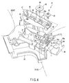
- FIG. 4 is an exploded perspective view of the panel fitting/removal mechanism K with part omitted
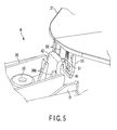
- FIG. 5 is a perspective view of part of the same mechanism K. Both FIGS. 4 and 5 show an inverted view of the indoor unit 1 suspended by the suspension bolts.
- the panel body 3A comprising the dress panel 21 includes an exposure surface (a) (shown in FIG. 1 ), which is exposed to the room.
- the exposure surface (a) has the height adjustment openings 20 provided in its corners, and the corner panels 21 fitted in the corresponding openings 20.
- the panel body 3A also includes a base surface disposed opposite the exposure surface (a) with a specific amount of space between the two faces and provided with the corner panel fitting/removal mechanism K mounted thereon.
- Each corner panel fitting/removal mechanism K includes a corner pedestal fixed to the base surface such that part of the support projects over the corresponding corner of the suction opening 17. Integrally provided on the corner pedestal is a swing member accommodating section 31. One end of the accommodating section 31 is located over the suction opening 17 while its other end faces the corner of the corresponding height adjustment opening 20.
- Each swing member accommodating section 31 is rectangular as viewed from above and has a recess formed by widthwise and lengthwise vertical walls.
- a screw fixing part 32 integrally projects from near the center of the bottom surface of the accommodating section 31.
- the screw fixing part 32 includes: a boss 32a with a screw hole (e) provided along its axis; and a semi-circular receiving portion 32b integrally projecting from the basal end of the boss 32a widthwise in the direction of the screw fixing part 32.
- a mounting boss 33 is provided at a given distance from the screw fixing part 32 of the swing member accommodating section 31 in the direction of the height adjustment opening 20.
- a screw for mounting each corner pedestal to the panel body 3A passes through this mounting boss 33.
- the mounting boss 33 has nothing to do with the action (described below) of the corner panel fitting/removal mechanism K.
- a screw operating part 35 is provided integrally with a suction opening 17 side vertical wall (f) comprising the swing member accommodating section 31.
- the screw operating part 35 is disposed in an area defined by both the vertical sidewalls and the suction opening 17 vertical side wall (f), which is one end of the accommodating section 31.
- the under surface of the screw operating part 35 is at a short distance from the bottom surface of the swing member accommodating part 31.
- a boss 35a with a screw insertion hole (g) provided along its axis.
- the hole (g) extends through the boss 35a from the upper to lower end.
- the other end of the swing member accommodating section 31, which end is opposite the screw operating part 35, accommodates no members.
- the upper end surface of the vertical wall (h) forming the end surface of the accommodating section 31 is low.
- a swing member 36 is accommodated in such a swing member accommodating section 31.
- the width and length of the swing member 36 is designed such that the swing member 36 may be accommodated in the accommodating section 31 with sufficient space left between them.
- the suction opening 17 side end may be inserted between the bottom surface of the accommodating section 31 and the under surface of the screw operating section 35.
- Substantially in the center of the swing member accommodating section 31 is an oblong circular fixing screw hole 37, which extends lengthwise in the direction of the accommodating section 31.
- Semi-circular support ribs 36a are provided on both sides of the fixing screw hole 37.
- the support ribs 36a are provided lengthwise in the direction of the swing member accommodating section 31, and correspond to the semi-circular direction of the receiving part 32b forming the fixing boss 32 of the swing member accommodating section 31.
- a predetermined distance from the fixing screw hole 37 in the direction of the height adjustment opening 20 is a boss escape hole 38 of oblong shape.
- an operating screw hole 40 Provided in one end of the swing member 36 is an operating screw hole 40. Inserting one end of the swing member 36 into a gap between the bottom surface of the swing member accommodating section 31 and the under surface of the operation part 35 and then adjusting the position of the swing member 36 allows the operating screw hole 40 to communicate with the insertion hole (g) of the screw operation part 35.
- a hooking piece 42 Integrally provided on the other end of the swing member 36 is a hooking piece 42 that has a hooking pawl 41.
- the hooking piece 42 projects upward from a vertical wall forming the end of the swing member 36, and a pair of reinforcement ribs 36b are provided on the inner surface of the hooking piece.
- the hooking pawl 41 is provided at the upper end of the hooking piece 42 and extends toward the height adjustment opening 20 located outside the end of the swing member 36.
- each of the corner panel fitting/removal mechanisms K requires an operation screw 44 passing through a washer 43 and screwed into the operating screw hole 40 of the swing member 36 via the screw insertion hole (g) of the screw operation part 35.
- the mechanism K also requires a fixing screw 46 passing through a washer 45 and screwed into the screw hole (e) of the screw fixing part 32 of the swing member accommodating part 31.
- the mechanism K requires a screw pressing metal fitting 48 bent into a substantially U-shape, which fits over the vertical wall (f) comprising the swing member 36 and screw operation part 35.
- the upper bent portion of the screw pressing metal fitting 48 functions as a pressing portion 48, which has a notch 49 extending from the leading edge of the pressing portion 48a into the vicinity of the bend in the metal fitting 48.
- the mechanism K requires a locking piece 50, which is provided integrally on the under surface of the corner panel 21 located opposite the corresponding corner of the suction opening 17.
- the locking piece 50 has an engagement hole 51, which is able to engage with the hooking pawl 41 of the swing member 36.
- a pair of ribs 52 extend from the upper end of the engagement hole 51 to the under surface of the corner panel 21.
- the corner panel fitting/removal mechanism K having the foregoing configuration is assembled in a manner as described below.
- the operating screw hole 40 side end of the swing member 36 is inserted into the gap between the swing member accommodating part 31 and the screw operation part 35. Consequently, the boss 32a of the screw fixing part 32 is passed through the fixing screw hole 37 and projects from the swing member 36; the swing member 36 is placed over the receiving part 32b and the mounting boss 33 is passed through the boss escape hole 38.
- the position of the swing member 36 is finely adjusted to exactly place the operating screw hole 40 in the screw insertion hole (g) in the operation part 35. Then, the operation screw 44 with the washer 43 fitted under the screw 44 is screwed into the operating screw hole 40 via the screw insertion hole (g). As a result, the washer 43 sits on the upper end of the boss 35a and the one end of the swing member 36 is raised.
- the one end of the swing member 36 comes into close contact with the under surface of the screw operation part 35.
- the operation screw 40 is loosely fastened. Accordingly one end of the swing member 36 is freely displaced vertically between the bottom surface of the swing member accommodating part 31 and the screw operating part 35.
- the screw pressing metal fitting 48 tightly holds therein the vertical wall (f) comprising both the swing member accommodating member 31 and screw operation part 35. Consequently, the operation screw 44 is compressed into recessed part 49 of the pressing portion 48a of the screw pressing metal fitting 48 from a horizontal direction so that the head of the operation screw 44 projects from the recessed part 49 and the pressing portion 48a rests on the washer 43. Accordingly, the screw pressing metal fitting 48 presses the operation screw 44 and vertical wall (f) together.
- the operation screw 44 is tightened, the one end of the swing member 36, in which the operating screw hole 40 is provided, goes up around the receiving portion 32b (which functions as a fulcrum), while the other end, at which the hooking piece 42 is provided, goes down. Conversely, if the operation screw 44 is loosened, one end of the swing member 36 goes down while the other end goes up. Thus, the swing member 36 moves in a seesaw manner.
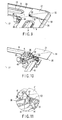
- FIG. 6 is a perspective view of part of the panel body 3A to which the corner panels 21 are fitted.
- FIG. 7 shows a condition in which the panel body 3A is removed from that shown in FIG. 6.
- FIG. 8 is an enlarged view of part of the view shown in FIG. 7 .
- FIG. 9 is a perspective view showing a condition in which part of the corner panel 21 juts out from the panel body.
- FIG. 10 shows a condition in which the panel body 3A is removed from that shown in FIG. 9.
- FIG. 11 is an enlarged view of part of the view shown in FIG. 10 .
- FIGS. 6 through 11 show the indoor unit 1 by turning the actual suspended position upside down.
- a description is given in the same direction as that in these drawings. Accordingly, in an actual situation, the directions of movements, motions, etc. will be opposite to those in the drawings.
- the screw operation part 35 which is part of the corner panel fitting/removal mechanism K, is exposed from the corresponding corner of the suction port 17.
- the pressing part 48a of the screw pressing metal fitting 48 and the head of the operation screw 44 compressed in the recessed part 49 from a horizontal direction are exposed.
- first corner a first projection 55 is provided at the corner (hereinafter referred to as the "first corner") located on the diagonal line extending from the opposite corner corresponding to the hooking piece 42; second projections 56 are provided at the two other corners thereof (hereinafter referred to as “second corners”), which will be located on the edges of the panel body 3A.
- Holes are made in a wall defining the corner of the corresponding height adjustment opening 20, which corner faces these first and second corners provided with the first and second projections 55 and 56 respectively.
- the corner panel 21 By engaging the first projection 55 and second projections 56 with the corresponding holes, the corner panel 21 completely covers the corresponding height adjustment opening 20, as shown in FIG. 6 .
- Corner panels 21 are fitted in the corresponding height adjustment openings 20 of the panel body 3A in the manner described below.
- the first projection 55 at the first corner of each corner panel 21 is inserted into the corresponding hole in the wall defining the height adjustment opening 20.
- the lower ends of the ribs 52 of the corner panel 21 abut against the upper end of the hooking piece 42, as shown in FIGS. 5 and 9 to 11 , and is restricted from being further pressed.
- the hooking pawl 41 lightly engages with the engagement hole 51.
- the corner panel 21 is inclined to the panel body 3A such that the second projections 56 floating from the panel body 3A are exposed. Also, an gap is created between the panel body 3A and corner panel 21 such that the ribs 52 of the corner panel 21, part of the locking piece 50, part of the hooking piece 42, and the hooking pawl 41 are exposed in the gap.
- the swing member 36 with the screw hole 40 screwable onto the operation screw 44 may be swung urgingly.
- the swing member 36 inclines such that the screw hole 40 side end of the swing member 36 lifts and comes into contact with the under surface of the screw operation part 35 while the hooking piece 42 comes close to the bottom surface of the swing member accommodating part 31.
- the hooking pawl 41 gradually engages with the engagement hole 51 and, at the same time, is pulled downward integrally with the hooking piece 42. Consequently, the locking piece 50 and the corner of corner panel 21 are pulled toward the height adjustment opening 20. By further fastening the operation screw 44, the hooking pawl 41 enters deeply into the engagement hole 51, thereby securely locking the corner panel 21 in position.
- the corner panels 21 completely fit in the corresponding height adjustment openings 20 such that the second projections 56 of the corner panels 21 engage with the holes of the wall defining the height adjustment openings 20. Consequently the corner panels 21 are securely fixed in the same plane as the panel body 3A such that the corner panels 21 cannot be removed from the surface of the panel body 3A.
- the suction opening 17 is opened as shown in FIG. 6 , thereby exposing the screw operating part 35 of the corner panel fitting/removal mechanism K fitted in each corner. Then, using a tool, each operation screw 44 is rotated in a loosening direction. Consequently, the corresponding swing member 36 swings such that the operating screw hole 40 side end is pulled down while the hooking piece 42 side end is pulled up toward the corresponding height adjustment opening 20.
- the hooking claw 41 lifts the locking piece 50 via the engagement hole 51, and the second corners of the corner panel 21 float from the surface of the panel body 3A in the direction of separation. Consequently, the corner panel 21 is inclined such that part of the corner panel 21 projects from the panel body 3A and the second projections 56 disengage from the holes. The first projection 55 at the first corner remains engaged with the hole.
- the corner panels 21 are only supported on the panel body 3A with a weak locking force. Accordingly, by pulling the corner panel 21 from the panel body 3A in the direction of separation, the engagement hole 51 disengages from the hooking pawl 41, the first projection 55 also disengages from the hole, and thus the corner panel 21 can be removed from the panel body 3A.
- a person undertaking the task described above must look up toward the dress panel 3 exposed from the ceiling. The person also tightens or loosens the operation screw 44 while looking upward. However, the screw pressing metal fitting 48 presses the operation screw 44, thus preventing the screw 44 from falling in the course of the task. In this way, the task can be efficiently performed.
- the swing member 36 and other components do not fall either.
- This corner panel fitting/removal mechanism K makes it possible to fit or remove the corner panels without sliding the corner panels diagonally as in conventional technique, thus improving efficiency in this task and increasing the freedom of design.
- FIG. 12 is a perspective sectional view of a section extending from the suction grill 18 of the dress panel 3 to each blower opening 19, and FIG. 13 is an enlarged view of part of the section. Both diagrams show the actual suspended position of the indoor unit 1.
- the surface of the panel body 3A with the suction opening 17 therein has a step 60 along the edges of the four sides of the panel body 3A.
- the step has an outward bend formed from the surface of the panel body 3A.
- the suction grill 18 has outward protruding part 18a formed integrally along the edges of the four sides of the surface of the suction grill 18. When the suction grill 18 is fitted in the suction opening 17, the protruding part 18a of the suction grill 18 is inserted in the step 60 of the panel body 3A.
- the protruding part 18a fills a gap between the suction opening 17 and the suction grill 18.
- the step 60 makes a joint between the suction grill 18 and the panel body 3A less conspicuous, contributing to the thin, improved design of the suction grill 18.
- the gap between the suction opening 17 and suction grill 18 narrows, allowing less air to enter. This decreases the quantity of air that does not pass through the filter attached to the suction grill 18, thus improving efficiency of the filter in trapping dust.
- the present invention increases freedom of design and allows the fitting or removal of corner panels irrespective of the installation location of an indoor unit.
Applications Claiming Priority (2)
| Application Number | Priority Date | Filing Date | Title |
|---|---|---|---|
| JP2006127072 | 2006-04-28 | ||
| PCT/JP2007/059103 WO2007126019A1 (ja) | 2006-04-28 | 2007-04-26 | 空気調和装置の室内ユニット |
Publications (3)
| Publication Number | Publication Date |
|---|---|
| EP2017543A1 true EP2017543A1 (de) | 2009-01-21 |
| EP2017543A4 EP2017543A4 (de) | 2013-12-11 |
| EP2017543B1 EP2017543B1 (de) | 2015-08-19 |
Family
ID=38655543
Family Applications (1)
| Application Number | Title | Priority Date | Filing Date |
|---|---|---|---|
| EP07742538.7A Active EP2017543B1 (de) | 2006-04-28 | 2007-04-26 | Innenraumeinheit für klimaanlage |
Country Status (4)
| Country | Link |
|---|---|
| EP (1) | EP2017543B1 (de) |
| JP (1) | JP4582817B2 (de) |
| CN (1) | CN101517328B (de) |
| WO (1) | WO2007126019A1 (de) |
Cited By (6)
| Publication number | Priority date | Publication date | Assignee | Title |
|---|---|---|---|---|
| EP2083224A3 (de) * | 2008-01-28 | 2011-04-13 | LG Electronics Inc. | Deckenklimaanlage mit Filterreinigungsmechanismus |
| JP2013217554A (ja) * | 2012-04-06 | 2013-10-24 | Daikin Industries Ltd | 空気調和機 |
| JPWO2012169110A1 (ja) * | 2011-06-09 | 2015-02-23 | 三菱電機株式会社 | 空気調和機の室内機 |
| EP3081876A3 (de) * | 2015-03-26 | 2017-01-11 | Fujitsu General Limited | Deckenintegrierte klimaanlage |
| EP3187794A1 (de) * | 2015-12-31 | 2017-07-05 | Lg Electronics Inc. | Klimaanlage |
| EP3587952A4 (de) * | 2017-02-27 | 2020-11-25 | Toshiba Carrier Corporation | Deckenplatte und klimaanlage |
Families Citing this family (3)
| Publication number | Priority date | Publication date | Assignee | Title |
|---|---|---|---|---|
| JP5234292B2 (ja) * | 2010-02-12 | 2013-07-10 | 株式会社富士通ゼネラル | 空気調和機 |
| JP6481818B2 (ja) * | 2015-03-31 | 2019-03-13 | 株式会社富士通ゼネラル | 天井埋込型空気調和機 |
| CN106016471A (zh) * | 2016-07-13 | 2016-10-12 | 海信(山东)空调有限公司 | 嵌入式空调 |
Citations (5)
| Publication number | Priority date | Publication date | Assignee | Title |
|---|---|---|---|---|
| JPH07324769A (ja) * | 1994-06-01 | 1995-12-12 | Daikin Ind Ltd | 空調機用化粧パネルの化粧蓋支持構造 |
| EP1139034A1 (de) * | 1999-01-25 | 2001-10-04 | Mitsubishi Denki Kabushiki Kaisha | In Raumdecke eingebaute Klimaanlage |
| US20020177400A1 (en) * | 1999-01-25 | 2002-11-28 | Mitsubishi Denki Kabushiki Kaisha | Ceiling embedded-type air conditioner |
| EP1327829A1 (de) * | 2002-01-10 | 2003-07-16 | Mitsubishi Denki Kabushiki Kaisha | In Raumdecke eingebaute Klimaanlage |
| JP2004085002A (ja) * | 2002-08-23 | 2004-03-18 | Advanced Kucho Kaihatsu Center Kk | 空気調和機の室内機 |
Family Cites Families (1)
| Publication number | Priority date | Publication date | Assignee | Title |
|---|---|---|---|---|
| CN2424405Y (zh) * | 2000-04-24 | 2001-03-21 | 大金工业株式会社 | 空调装置 |
-
2007
- 2007-04-26 CN CN2007800153217A patent/CN101517328B/zh active Active
- 2007-04-26 WO PCT/JP2007/059103 patent/WO2007126019A1/ja active Application Filing
- 2007-04-26 JP JP2008513270A patent/JP4582817B2/ja not_active Expired - Fee Related
- 2007-04-26 EP EP07742538.7A patent/EP2017543B1/de active Active
Patent Citations (5)
| Publication number | Priority date | Publication date | Assignee | Title |
|---|---|---|---|---|
| JPH07324769A (ja) * | 1994-06-01 | 1995-12-12 | Daikin Ind Ltd | 空調機用化粧パネルの化粧蓋支持構造 |
| EP1139034A1 (de) * | 1999-01-25 | 2001-10-04 | Mitsubishi Denki Kabushiki Kaisha | In Raumdecke eingebaute Klimaanlage |
| US20020177400A1 (en) * | 1999-01-25 | 2002-11-28 | Mitsubishi Denki Kabushiki Kaisha | Ceiling embedded-type air conditioner |
| EP1327829A1 (de) * | 2002-01-10 | 2003-07-16 | Mitsubishi Denki Kabushiki Kaisha | In Raumdecke eingebaute Klimaanlage |
| JP2004085002A (ja) * | 2002-08-23 | 2004-03-18 | Advanced Kucho Kaihatsu Center Kk | 空気調和機の室内機 |
Non-Patent Citations (1)
| Title |
|---|
| See also references of WO2007126019A1 * |
Cited By (12)
| Publication number | Priority date | Publication date | Assignee | Title |
|---|---|---|---|---|
| EP2083224A3 (de) * | 2008-01-28 | 2011-04-13 | LG Electronics Inc. | Deckenklimaanlage mit Filterreinigungsmechanismus |
| JPWO2012169110A1 (ja) * | 2011-06-09 | 2015-02-23 | 三菱電機株式会社 | 空気調和機の室内機 |
| JP2015180847A (ja) * | 2011-06-09 | 2015-10-15 | 三菱電機株式会社 | 空気調和機の室内機 |
| US9574815B2 (en) | 2011-06-09 | 2017-02-21 | Mitsubishi Electric Corporation | Air-conditioning-apparatus indoor unit |
| US10429088B2 (en) | 2011-06-09 | 2019-10-01 | Mitsubishi Electric Corporation | Air-conditioning-apparatus indoor unit |
| JP2013217554A (ja) * | 2012-04-06 | 2013-10-24 | Daikin Industries Ltd | 空気調和機 |
| EP3081876A3 (de) * | 2015-03-26 | 2017-01-11 | Fujitsu General Limited | Deckenintegrierte klimaanlage |
| EP3270074A1 (de) * | 2015-03-26 | 2018-01-17 | Fujitsu General Limited | In raumdecke eingebettete klimaanlage |
| AU2016201838B2 (en) * | 2015-03-26 | 2021-05-20 | Fujitsu General Limited | Ceiling-Embedded Air Conditioner |
| EP3187794A1 (de) * | 2015-12-31 | 2017-07-05 | Lg Electronics Inc. | Klimaanlage |
| US10544947B2 (en) | 2015-12-31 | 2020-01-28 | Lg Electronics Inc. | Air conditioner |
| EP3587952A4 (de) * | 2017-02-27 | 2020-11-25 | Toshiba Carrier Corporation | Deckenplatte und klimaanlage |
Also Published As
| Publication number | Publication date |
|---|---|
| CN101517328B (zh) | 2012-05-30 |
| EP2017543A4 (de) | 2013-12-11 |
| EP2017543B1 (de) | 2015-08-19 |
| WO2007126019A1 (ja) | 2007-11-08 |
| JP4582817B2 (ja) | 2010-11-17 |
| CN101517328A (zh) | 2009-08-26 |
| JPWO2007126019A1 (ja) | 2009-09-10 |
Similar Documents
| Publication | Publication Date | Title |
|---|---|---|
| EP2017543B1 (de) | Innenraumeinheit für klimaanlage | |
| EP1248048B1 (de) | Klimaanlage | |
| JP4582818B2 (ja) | 空気調和装置の室内ユニット | |
| JP5786123B2 (ja) | 天井埋込形換気扇 | |
| JPH03230030A (ja) | 一体形空気調和機 | |
| JP6439537B2 (ja) | 天井埋込型空気調和機 | |
| JP3284755B2 (ja) | 空調機用化粧パネルの化粧蓋支持構造及び空気調和装置 | |
| JP2003097821A (ja) | 空気調和機 | |
| JP2001116279A (ja) | 天井埋込形空気調和機 | |
| JP2001147042A (ja) | 天井埋込形空気調和機 | |
| JP2007205589A (ja) | 天井カセット形空気調和機 | |
| JP2004085002A (ja) | 空気調和機の室内機 | |
| JP2004084998A (ja) | 空気調和機の室内機 | |
| JP2001263714A (ja) | 天井埋込型空気調和機 | |
| JP2988408B2 (ja) | 高所設置用空気調和機 | |
| JP5033535B2 (ja) | 天井埋込型空気調和機 | |
| JP2664472B2 (ja) | 天井埋込型空気調和ユニット | |
| JP7233034B2 (ja) | 空気調和装置の室内機 | |
| JP2001099481A (ja) | 天井埋込型空気調和機 | |
| JP2023108473A (ja) | 室内機 | |
| JPH0742040Y2 (ja) | 空気調和機のファンの吹出口構造 | |
| JP4214621B2 (ja) | 天井埋込型空気調和機 | |
| JP2869305B2 (ja) | 空気調和機の取付け装置 | |
| JPH0620026Y2 (ja) | 天井埋込式空気調和機 | |
| WO2018154765A1 (ja) | 天井パネルおよび空気調和機 |
Legal Events
| Date | Code | Title | Description |
|---|---|---|---|
| PUAI | Public reference made under article 153(3) epc to a published international application that has entered the european phase |
Free format text: ORIGINAL CODE: 0009012 |
|
| 17P | Request for examination filed |
Effective date: 20081128 |
|
| AK | Designated contracting states |
Kind code of ref document: A1 Designated state(s): AT BE BG CH CY CZ DE DK EE ES FI FR GB GR HU IE IS IT LI LT LU LV MC MT NL PL PT RO SE SI SK TR |
|
| AX | Request for extension of the european patent |
Extension state: AL BA HR MK RS |
|
| DAX | Request for extension of the european patent (deleted) | ||
| A4 | Supplementary search report drawn up and despatched |
Effective date: 20131111 |
|
| RIC1 | Information provided on ipc code assigned before grant |
Ipc: F24F 1/00 20110101ALI20131105BHEP Ipc: F24F 13/20 20060101AFI20131105BHEP |
|
| GRAP | Despatch of communication of intention to grant a patent |
Free format text: ORIGINAL CODE: EPIDOSNIGR1 |
|
| RIC1 | Information provided on ipc code assigned before grant |
Ipc: F24F 13/20 20060101AFI20150217BHEP Ipc: F24F 13/06 20060101ALI20150217BHEP Ipc: F24F 1/00 20110101ALI20150217BHEP |
|
| INTG | Intention to grant announced |
Effective date: 20150317 |
|
| GRAS | Grant fee paid |
Free format text: ORIGINAL CODE: EPIDOSNIGR3 |
|
| GRAA | (expected) grant |
Free format text: ORIGINAL CODE: 0009210 |
|
| AK | Designated contracting states |
Kind code of ref document: B1 Designated state(s): AT BE BG CH CY CZ DE DK EE ES FI FR GB GR HU IE IS IT LI LT LU LV MC MT NL PL PT RO SE SI SK TR |
|
| REG | Reference to a national code |
Ref country code: GB Ref legal event code: FG4D |
|
| REG | Reference to a national code |
Ref country code: CH Ref legal event code: EP |
|
| REG | Reference to a national code |
Ref country code: IE Ref legal event code: FG4D |
|
| REG | Reference to a national code |
Ref country code: AT Ref legal event code: REF Ref document number: 744091 Country of ref document: AT Kind code of ref document: T Effective date: 20150915 |
|
| REG | Reference to a national code |
Ref country code: DE Ref legal event code: R096 Ref document number: 602007042665 Country of ref document: DE |
|
| REG | Reference to a national code |
Ref country code: AT Ref legal event code: MK05 Ref document number: 744091 Country of ref document: AT Kind code of ref document: T Effective date: 20150819 |
|
| REG | Reference to a national code |
Ref country code: LT Ref legal event code: MG4D |
|
| REG | Reference to a national code |
Ref country code: NL Ref legal event code: MP Effective date: 20150819 |
|
| PG25 | Lapsed in a contracting state [announced via postgrant information from national office to epo] |
Ref country code: FI Free format text: LAPSE BECAUSE OF FAILURE TO SUBMIT A TRANSLATION OF THE DESCRIPTION OR TO PAY THE FEE WITHIN THE PRESCRIBED TIME-LIMIT Effective date: 20150819 Ref country code: LV Free format text: LAPSE BECAUSE OF FAILURE TO SUBMIT A TRANSLATION OF THE DESCRIPTION OR TO PAY THE FEE WITHIN THE PRESCRIBED TIME-LIMIT Effective date: 20150819 Ref country code: GR Free format text: LAPSE BECAUSE OF FAILURE TO SUBMIT A TRANSLATION OF THE DESCRIPTION OR TO PAY THE FEE WITHIN THE PRESCRIBED TIME-LIMIT Effective date: 20151120 Ref country code: LT Free format text: LAPSE BECAUSE OF FAILURE TO SUBMIT A TRANSLATION OF THE DESCRIPTION OR TO PAY THE FEE WITHIN THE PRESCRIBED TIME-LIMIT Effective date: 20150819 |
|
| PG25 | Lapsed in a contracting state [announced via postgrant information from national office to epo] |
Ref country code: AT Free format text: LAPSE BECAUSE OF FAILURE TO SUBMIT A TRANSLATION OF THE DESCRIPTION OR TO PAY THE FEE WITHIN THE PRESCRIBED TIME-LIMIT Effective date: 20150819 Ref country code: SE Free format text: LAPSE BECAUSE OF FAILURE TO SUBMIT A TRANSLATION OF THE DESCRIPTION OR TO PAY THE FEE WITHIN THE PRESCRIBED TIME-LIMIT Effective date: 20150819 Ref country code: ES Free format text: LAPSE BECAUSE OF FAILURE TO SUBMIT A TRANSLATION OF THE DESCRIPTION OR TO PAY THE FEE WITHIN THE PRESCRIBED TIME-LIMIT Effective date: 20150819 Ref country code: PT Free format text: LAPSE BECAUSE OF FAILURE TO SUBMIT A TRANSLATION OF THE DESCRIPTION OR TO PAY THE FEE WITHIN THE PRESCRIBED TIME-LIMIT Effective date: 20151221 Ref country code: PL Free format text: LAPSE BECAUSE OF FAILURE TO SUBMIT A TRANSLATION OF THE DESCRIPTION OR TO PAY THE FEE WITHIN THE PRESCRIBED TIME-LIMIT Effective date: 20150819 Ref country code: IS Free format text: LAPSE BECAUSE OF FAILURE TO SUBMIT A TRANSLATION OF THE DESCRIPTION OR TO PAY THE FEE WITHIN THE PRESCRIBED TIME-LIMIT Effective date: 20151219 |
|
| REG | Reference to a national code |
Ref country code: FR Ref legal event code: PLFP Year of fee payment: 10 |
|
| PG25 | Lapsed in a contracting state [announced via postgrant information from national office to epo] |
Ref country code: NL Free format text: LAPSE BECAUSE OF FAILURE TO SUBMIT A TRANSLATION OF THE DESCRIPTION OR TO PAY THE FEE WITHIN THE PRESCRIBED TIME-LIMIT Effective date: 20150819 |
|
| PG25 | Lapsed in a contracting state [announced via postgrant information from national office to epo] |
Ref country code: DK Free format text: LAPSE BECAUSE OF FAILURE TO SUBMIT A TRANSLATION OF THE DESCRIPTION OR TO PAY THE FEE WITHIN THE PRESCRIBED TIME-LIMIT Effective date: 20150819 Ref country code: CZ Free format text: LAPSE BECAUSE OF FAILURE TO SUBMIT A TRANSLATION OF THE DESCRIPTION OR TO PAY THE FEE WITHIN THE PRESCRIBED TIME-LIMIT Effective date: 20150819 Ref country code: IT Free format text: LAPSE BECAUSE OF FAILURE TO SUBMIT A TRANSLATION OF THE DESCRIPTION OR TO PAY THE FEE WITHIN THE PRESCRIBED TIME-LIMIT Effective date: 20150819 Ref country code: EE Free format text: LAPSE BECAUSE OF FAILURE TO SUBMIT A TRANSLATION OF THE DESCRIPTION OR TO PAY THE FEE WITHIN THE PRESCRIBED TIME-LIMIT Effective date: 20150819 Ref country code: SK Free format text: LAPSE BECAUSE OF FAILURE TO SUBMIT A TRANSLATION OF THE DESCRIPTION OR TO PAY THE FEE WITHIN THE PRESCRIBED TIME-LIMIT Effective date: 20150819 |
|
| REG | Reference to a national code |
Ref country code: DE Ref legal event code: R097 Ref document number: 602007042665 Country of ref document: DE |
|
| PG25 | Lapsed in a contracting state [announced via postgrant information from national office to epo] |
Ref country code: RO Free format text: LAPSE BECAUSE OF FAILURE TO SUBMIT A TRANSLATION OF THE DESCRIPTION OR TO PAY THE FEE WITHIN THE PRESCRIBED TIME-LIMIT Effective date: 20150819 |
|
| PLBE | No opposition filed within time limit |
Free format text: ORIGINAL CODE: 0009261 |
|
| STAA | Information on the status of an ep patent application or granted ep patent |
Free format text: STATUS: NO OPPOSITION FILED WITHIN TIME LIMIT |
|
| 26N | No opposition filed |
Effective date: 20160520 |
|
| PG25 | Lapsed in a contracting state [announced via postgrant information from national office to epo] |
Ref country code: SI Free format text: LAPSE BECAUSE OF FAILURE TO SUBMIT A TRANSLATION OF THE DESCRIPTION OR TO PAY THE FEE WITHIN THE PRESCRIBED TIME-LIMIT Effective date: 20150819 Ref country code: BE Free format text: LAPSE BECAUSE OF NON-PAYMENT OF DUE FEES Effective date: 20160430 |
|
| REG | Reference to a national code |
Ref country code: CH Ref legal event code: PL |
|
| PG25 | Lapsed in a contracting state [announced via postgrant information from national office to epo] |
Ref country code: LU Free format text: LAPSE BECAUSE OF FAILURE TO SUBMIT A TRANSLATION OF THE DESCRIPTION OR TO PAY THE FEE WITHIN THE PRESCRIBED TIME-LIMIT Effective date: 20160426 Ref country code: BE Free format text: LAPSE BECAUSE OF FAILURE TO SUBMIT A TRANSLATION OF THE DESCRIPTION OR TO PAY THE FEE WITHIN THE PRESCRIBED TIME-LIMIT Effective date: 20150819 |
|
| REG | Reference to a national code |
Ref country code: IE Ref legal event code: MM4A |
|
| PG25 | Lapsed in a contracting state [announced via postgrant information from national office to epo] |
Ref country code: LI Free format text: LAPSE BECAUSE OF NON-PAYMENT OF DUE FEES Effective date: 20160430 Ref country code: CH Free format text: LAPSE BECAUSE OF NON-PAYMENT OF DUE FEES Effective date: 20160430 |
|
| REG | Reference to a national code |
Ref country code: FR Ref legal event code: PLFP Year of fee payment: 11 |
|
| PG25 | Lapsed in a contracting state [announced via postgrant information from national office to epo] |
Ref country code: IE Free format text: LAPSE BECAUSE OF NON-PAYMENT OF DUE FEES Effective date: 20160426 |
|
| REG | Reference to a national code |
Ref country code: FR Ref legal event code: PLFP Year of fee payment: 12 |
|
| PG25 | Lapsed in a contracting state [announced via postgrant information from national office to epo] |
Ref country code: HU Free format text: LAPSE BECAUSE OF FAILURE TO SUBMIT A TRANSLATION OF THE DESCRIPTION OR TO PAY THE FEE WITHIN THE PRESCRIBED TIME-LIMIT; INVALID AB INITIO Effective date: 20070426 Ref country code: CY Free format text: LAPSE BECAUSE OF FAILURE TO SUBMIT A TRANSLATION OF THE DESCRIPTION OR TO PAY THE FEE WITHIN THE PRESCRIBED TIME-LIMIT Effective date: 20150819 |
|
| PG25 | Lapsed in a contracting state [announced via postgrant information from national office to epo] |
Ref country code: MC Free format text: LAPSE BECAUSE OF FAILURE TO SUBMIT A TRANSLATION OF THE DESCRIPTION OR TO PAY THE FEE WITHIN THE PRESCRIBED TIME-LIMIT Effective date: 20150819 Ref country code: MT Free format text: LAPSE BECAUSE OF NON-PAYMENT OF DUE FEES Effective date: 20160430 Ref country code: TR Free format text: LAPSE BECAUSE OF FAILURE TO SUBMIT A TRANSLATION OF THE DESCRIPTION OR TO PAY THE FEE WITHIN THE PRESCRIBED TIME-LIMIT Effective date: 20150819 |
|
| PG25 | Lapsed in a contracting state [announced via postgrant information from national office to epo] |
Ref country code: BG Free format text: LAPSE BECAUSE OF FAILURE TO SUBMIT A TRANSLATION OF THE DESCRIPTION OR TO PAY THE FEE WITHIN THE PRESCRIBED TIME-LIMIT Effective date: 20150819 |
|
| PGFP | Annual fee paid to national office [announced via postgrant information from national office to epo] |
Ref country code: FR Payment date: 20230309 Year of fee payment: 17 |
|
| PGFP | Annual fee paid to national office [announced via postgrant information from national office to epo] |
Ref country code: DE Payment date: 20230228 Year of fee payment: 17 |
|
| PGFP | Annual fee paid to national office [announced via postgrant information from national office to epo] |
Ref country code: GB Payment date: 20240307 Year of fee payment: 18 |