EP2017403B1 - Système de plancher - Google Patents
Système de plancher Download PDFInfo
- Publication number
- EP2017403B1 EP2017403B1 EP08013108A EP08013108A EP2017403B1 EP 2017403 B1 EP2017403 B1 EP 2017403B1 EP 08013108 A EP08013108 A EP 08013108A EP 08013108 A EP08013108 A EP 08013108A EP 2017403 B1 EP2017403 B1 EP 2017403B1
- Authority
- EP
- European Patent Office
- Prior art keywords
- arm
- tongue
- groove
- locking member
- rotatable
- Prior art date
- Legal status (The legal status is an assumption and is not a legal conclusion. Google has not performed a legal analysis and makes no representation as to the accuracy of the status listed.)
- Active
Links
Images


Classifications
-
- E—FIXED CONSTRUCTIONS
- E04—BUILDING
- E04F—FINISHING WORK ON BUILDINGS, e.g. STAIRS, FLOORS
- E04F15/00—Flooring
- E04F15/02—Flooring or floor layers composed of a number of similar elements
-
- E—FIXED CONSTRUCTIONS
- E04—BUILDING
- E04F—FINISHING WORK ON BUILDINGS, e.g. STAIRS, FLOORS
- E04F15/00—Flooring
- E04F15/02—Flooring or floor layers composed of a number of similar elements
- E04F15/04—Flooring or floor layers composed of a number of similar elements only of wood or with a top layer of wood, e.g. with wooden or metal connecting members
-
- E—FIXED CONSTRUCTIONS
- E04—BUILDING
- E04F—FINISHING WORK ON BUILDINGS, e.g. STAIRS, FLOORS
- E04F2201/00—Joining sheets or plates or panels
- E04F2201/01—Joining sheets, plates or panels with edges in abutting relationship
- E04F2201/0138—Joining sheets, plates or panels with edges in abutting relationship by moving the sheets, plates or panels perpendicular to the main plane
-
- E—FIXED CONSTRUCTIONS
- E04—BUILDING
- E04F—FINISHING WORK ON BUILDINGS, e.g. STAIRS, FLOORS
- E04F2201/00—Joining sheets or plates or panels
- E04F2201/05—Separate connectors or inserts, e.g. pegs, pins, keys or strips
- E04F2201/0523—Separate tongues; Interlocking keys, e.g. joining mouldings of circular, square or rectangular shape
- E04F2201/0552—Separate tongues; Interlocking keys, e.g. joining mouldings of circular, square or rectangular shape adapted to be rotated around an axis parallel to the joint edge
-
- F—MECHANICAL ENGINEERING; LIGHTING; HEATING; WEAPONS; BLASTING
- F16—ENGINEERING ELEMENTS AND UNITS; GENERAL MEASURES FOR PRODUCING AND MAINTAINING EFFECTIVE FUNCTIONING OF MACHINES OR INSTALLATIONS; THERMAL INSULATION IN GENERAL
- F16B—DEVICES FOR FASTENING OR SECURING CONSTRUCTIONAL ELEMENTS OR MACHINE PARTS TOGETHER, e.g. NAILS, BOLTS, CIRCLIPS, CLAMPS, CLIPS OR WEDGES; JOINTS OR JOINTING
- F16B2200/00—Constructional details of connections not covered for in other groups of this subclass
- F16B2200/69—Redundant disconnection blocking means
- F16B2200/73—Cam locks or thread locks
-
- Y—GENERAL TAGGING OF NEW TECHNOLOGICAL DEVELOPMENTS; GENERAL TAGGING OF CROSS-SECTIONAL TECHNOLOGIES SPANNING OVER SEVERAL SECTIONS OF THE IPC; TECHNICAL SUBJECTS COVERED BY FORMER USPC CROSS-REFERENCE ART COLLECTIONS [XRACs] AND DIGESTS
- Y10—TECHNICAL SUBJECTS COVERED BY FORMER USPC
- Y10T—TECHNICAL SUBJECTS COVERED BY FORMER US CLASSIFICATION
- Y10T403/00—Joints and connections
- Y10T403/76—Joints and connections having a cam, wedge, or tapered portion
Definitions
- the present invention generally relates to flooring systems. More particularly, the present invention relates to mechanical locking joints for connecting flooring panels.
- Flooring systems are available in a variety of forms, such as fine wood, tile (e.g. granite, brick, slate, etc.), and concrete.
- Laminate flooring such as laminates and high-pressure laminate boards (HPL) may also be a popular substitute for traditional flooring materials as they tend to be generally less expensive to produce. Regardless of which type of flooring is desired, it is generally preferable to the user that installation be simple, such that it is not necessary to hire a professional to install the system.
- Some of the related art flooring systems do not require gluing or nailing the flooring system to the base floor during installation. These types of flooring systems are popularly known as "floating floors” as they do not generally rigidly connect to a base floor. Many floating floors may employ some type of interlocking joint system.
- tongue-and-groove-type connection One type of interlocking joint is known as a tongue-and-groove-type connection, where each board has a tongue extending along one edge and a mating groove extending along an opposite edge. Accordingly, when installing the flooring panels the tongue of one panel is fitted into the grove of an adjacent panel.
- tongue and groove connections for floor panels utilize a snap-together joint. With this type of connection generally the tongue or groove will have an additional protrusion or indentation that will serve to "snap" adjacent panels together when a force is exerted to push the adjacent panels together.
- laminate flooring offers several advantages, such as lower production cost. Further, most laminate flooring is of the "floating floor” type utilizing an interlocking joint system, which may be considered uncomplicated and easier to install. It is noted that most laminate flooring systems employ some type of decorative motif on a surface of the panels to mimic the look and feel of traditional flooring materials. In order to effectively create such a look, it may be very important to align the decorative motifs or graphics across the joints of adjacent panels. However, related joint systems in floor systems generally have the disadvantage of creating a visual disruption in the surface pattern of the laminate flooring. This significantly detracts from the visual and textural impression of system, resulting in an unattractive appearance of the flooring when it is installed.
- flooring system that is inexpensive, employing a joint connection that is easy to install, resulting in an aesthetically pleasing and durable appearance.
- a flooring panel according to the preamble of claim 1 is already known from WO 2007/008139 A .
- the rotating cam of the known interlocking joint is U-shaped. This form of the rotatable cam may cause problems when panels have to be interlocked.
- Problem of the present invention is to establish a locking engagement preventing horizontal and vertical movement of first and second panels with respect to each other.
- the present invention provides a mechanical locking joint connection for use with flooring systems.
- one advantage of the present invention is to provide a mechanical joint system that connects adjacent floor panels. Another advantage of the present invention is to prove a mechanical joint system that is easy to install. Yet another advantage of the present invention is to provide a reliable connection that results in a pleasant aesthetic appearance.
- the present invention involves an interlocking joint having a first side defining a first mating portion along a first side and a second side defining a second mating portion along a second side, said second side disposed opposite said first side; the first mating portion having a substantially arcuate groove formed therein and extending along at least a portion of the first side; a rotatable cam disposed in the groove extending in a longitudinal direction along at least a portion of the first side; the rotatable cam having a central portion, a first arm extending radially outward from the central portion along a first axis, a second arm extending radially outward from the central portion along a second axis, and a resilient arm extending radially outward from the central portion along a third axis and disposed a distance from the second arm defined by a predetermined angle; the first arm having a lever portion and a curved portion, the curved portion extending substantially perpendicular to the lever portion defining
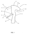
- FIG. 1 illustrates an exemplary rotatable locking member 10 according to the present invention, where the locking member 10 is in an unloaded state.
- Rotatable locking member 10 includes a central region 16 defined as the portion surrounding core aperture 20, and a first arm 18 extending radially from central region 16. Further, core aperture 20 has a predetermined radius R1, which may depend on the size of the rotatable locking member 10 and its particular application.
- First arm 18 defines a substantially hook-shaped member.
- the hook-shape of first arm 18 is created by the combination of lever portion 26 and curved portion 28.
- Lever portion 26 may gradually increase in width as it extends from central region 16.
- Curved portion 28 extends integrally from an end of lever portion 26, at a point farthest from central region 16 and at a substantially perpendicular or acute angle, to end in a substantially flat contact surface 30.
- First arm 18 further defines an arcuate hook groove 32 at an underside of thereof.
- a second arm 22 also extends radially from central region 16 in a direction substantially opposite and parallel to that of the first arm 20.
- Rotatable locking member further includes a resilient arm 24 extending radially from the central region 16. As illustrated in FIG. 1 , second arm 22 may increase in width as it extends from central region 16, and resilient arm 24 may decrease in width. Other shapes of the second arm 22 and the resilient arm 24 are envisioned, so long as they are enabled to provide a biasing force on the system, as discussed below.
- resilient arm 24 is radially offset from the first arm 18 by predetermined angle A1, and from the second arm 22 by predetermined angle A2.
- A1 is generally an obtuse angle
- A2 is generally an acute angle.
- the rotatable locking member 10 may be made of plastic, metal, or any suitable material that is resilient in nature such that it is capable of withstanding the forces imposed by the locking joint system while still exerting a biasing force as described below.
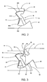
- FIG. 2 illustrates an exemplary embodiment where the locking member 10 is seated in a first panel 12.
- the panel 12 may be made from high-density fiber board (HDF), medium-density fiber board (MDF), particle board, composite, wood, or any other material used in flooring systems.
- First panel 12 has a first side 34 defining a first mating portion, which includes a partially arcuate groove 36, having a front, slot-like opening 38, an upper arc 36A and a lower arc 36B.
- Disposed between upper arc 36A and 36B is a angled back wall 40 having an upper wall 40A and a lower wall 40B.
- the angle between upper wall 40A and lower wall 40B is substantially the same as angle A1.
- Lower arc 36B ends at front side 34 to create a lower lip 42 that extends laterally in length beyond top edge 44.
- FIG. 3 illustrates the interlocking function as first panel 12, having rotatable locking member 10 seated therein, meets with second panel 14.
- Panel 14 may be constructed from substantially the same material as panel 12.
- Second panel 14 includes a second side 46 defining a second mating portion defined by tongue 48.
- Tongue 48 extends outwardly from second side 46 and continues along at least a portion of the length of second side 46. Further, the extension of tongue 48 from second side 46 creates a substantially concave groove 50 along an undersurface thereof and a receiving groove 52 along an upper surface thereof.
- first panel 12 may be in place on the floor and second panel 14 is oriented substantially parallel to the floor.
- Second panel 14 and tongue 48 are then lowered substantially vertically into the opening 38.
- a bottom edge 54 of tongue 48 contacts and presses against second arm 22 of the rotatable locking member 10.
- bottom edge 54 forces the rotational movement of second arm 22 toward resilient arm 24.
- Resilient arm remains stationary as it lies against lower wall 40B, which imposes a reactionary force maintaining the position of resilient arm 24. Accordingly, a bias force is created about core aperture 20, thus pushing first arm 18 forward such that surface 30 contacts top edge 56 of tongue 48.
- second panel 14 moves in a substantially vertical downward direction forcing tongue 48 to move second arm 22, thus decreasing angle A2.
- angle A1 increases respectively.
- Contact surface 30 of first arm 18 will continue to bear against top edge 56 due to the bias force as tongue 48 moves forward into opening 38.
- the first arm will move immediately a distance forward. This movement may be described as a "click" into a locking position, such that curved portion 28 mates with complimentarily shaped receiving groove 52.
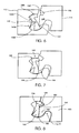
- FIG. 4 illustrates an exemplary view of the mechanical joint system in a connected or locked position.
- Tongue 48 is seated in a mating relationship with a groove created by the front surface of rotatable locking member 10, hook grove 32 and lip 42.
- Hook-shaped first arm 18 is biased forward and seated in receiving groove 52, thus preventing vertical movement of first 12 and second 14 panels with respect to one another.
- lower lip 42 is brought into mating alignment with concave groove 50, thus preventing horizontal movement of first 12 and second 14 panels with respect to one another.
- First arm 18 and second arm 22 maintain a vertical alignment in the locked position.
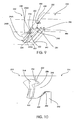
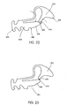
- FIG 5 a perspective view of the exemplary joint locking system is illustrated.
- Locking member 10 is inserted into first panel 12 at a side wall 60 thereof, and once inserted cannot be removed through slot-like groove 38.
- Rotatable locking member 10 may be constructed in various lengths in accordance with the scope of the invention. That is, locking member 10 may extend along the a portion of the length of first side 34 or second side 44 (sides), or it may extend along the entire length of the sides. Further, where the locking member 10 is of a size that it does not extend along the entire length of the sides, but only a portion thereof, it is envisioned that more than one locking member 10 may be employed.
- FIGs. 6 through 8 A further exemplary embodiment is illustrated in FIGs. 6 through 8 .
- the mechanical operation of the joint is similar to that described above with respect to FIGs. 2 though 4.
- second panel 114 is installed into first panel 112, and is held in place through rotatable locking member 110.
- the second panel 114 has a tongue 148 which mates with the rotatable locking member 110 seated in the opening 138.
- the second panel 114 is held horizontally so that the of the second panel 114 is oriented substantially parallel to the floor.
- the second panel 114 is lowered into the opening 138 of the first panel 112 substantially vertically, maintaining the second panel 114's substantially horizontal orientation with respect to the floor.
- the first arm 118 and the second arm 122 are not under tension with respect to each other, however the resilient arm 124 is compressed radially against the second arm 122 creating a force pressing the tongue 148 back against the lower lip 142, and also pressing the top edge 156 back against the curved portion 128 of the first arm 118, thereby establishing a locking engagement
- upper arc 136A and lower arc 136B of opening 138 are provided with slightly raised lip portions 162 and 164, respectively.
- the raised lip portion 162 and 164 engages a bump or raised tab 166 located at a top side of the first arm 118 opposite the curved portion 128 to prevent the first arm 118 from rotating out of the opening 138 causing the rotatable member 110 to fall out of the opening 138.
- the raised lip portion 164 on the lower arc 136B engages the front tip 166 of the second arm 122, preventing the second arm from rotating too far in the lower arc 136B, causing the rotatable member 110 to fall out of the opening.
- the raised lip portion 162 of the upper arc 136A is placed a sort distance back from the opening 138.
- the raised lip portion 164 of the lower arc 136B is placed near the base of the lower lip portion 142.
- the raised lip portion 162 may be placed in the upper arc 136A at a position such that when the second panel 114 is completely installed and the tongue 148 is seated entirely within the opening 138 and against the rotatable member 110, the raised tab 166 on the first arm 118 hits the raised lip portion 162 before the first arm 118 returns to its initial position. This would cause there to be some tension to remain between the first arm 118 and the second arm 122 during installation to establish a tighter locking between the tongue 148, the rotatable member 110, and the first panel 112.
- the angle separating the resilient arm 124 and the second arm 122 can be made large enough so that prior to installation, the front tip 166 of the second arm 122 is pressed slightly against the raised lip portion 164, maintaining the rotatable member 110 stationary in the opening 138, so that during manufacturing, shipping, and transport of the flooring panels, the rotatable member is not shaken loose of the opening 138.
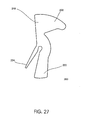
- FIGs. 5 , 9 , 10 and 27 A third embodiment of the present invention is illustrated in FIGs. 5 , 9 , 10 and 27 .
- the rotatable locking member 200 ( FIG.27 ) is provided with a head 202 at the end of first arm 218 having a substantially convex shape.
- the rotatable locking member 200 includes a second arm 222 and a resilient arm 224 having shapes similar to second arm 22 and resilient arm 24 in FIGs 1-4 . As illustrated in FIGs.
- the lower lip 242 is fully inserted into the concave groove 250. Because the top edge 256 of the tongue 248 passes below the convex shaped head 202 of the first arm 218, the tension generated by the bending back of the first arm 218 against the tope edge 256 of the tongue 248 is released, causing the first arm 218 to rotate forward such that the convex shaped head 202 fits into the groove 252. In this embodiment, the convex-shaped head 202 does not engage the groove 252, thus the lower lip 242 is provided with a substantially vertical surface 262 along some portion of its perimeter which is adjacent the rear surface 264 of the tongue 248. This prevents the adjacent flooring panels 212 and 214 from sliding completely apart.
- the tongue may be shaped such that space may be provided between the rotational locking member 200 and the front of the tongue 248. This space gives the rotational locking member 200 some flexibility to rotate or twist as the panels are installed or taken apart.
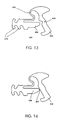
- FIGs.11 and 12 illustrate a second aspect of the third embodiment.
- the tongue 270 has substantially the same shape as tongue 248 of FIG.10 , with the difference that the rear surface 271 of the tongue 270 is a substantially smooth curve, lacking the vertical portion of rear surface 264 FIG.10 .
- the corresponding opening in the first panel 272 does not have a vertical surface on the lower lip 274. The absence of these two features allows the tongue 270 to slide more easily into the groove and to allow the flooring panels once installed to be removed or separated more easily.
- the angled back wall of the groove 276 has substantially the same shape as the angled back wall 240 of the first aspect illustrated in FIGs. 9 and 10 .
- the rotational member 278 has a curved resilient arm portion 280, in contrast to the substantially straight resilient arm member 224 of the previous aspect of the embodiment illustrated in FIG.9 .
- the curved arm portion 280 provides for greater flexibility and resiliency compared to the straight arm 224 illustrated in FIG.9 .
- the curved resilient arm portion 280 is pressed against the angled back wall of the groove 276, causing the curved resilient arm portion 280 to be flexed, or bent, into a substantially straight position.
- the force exerted by the tongue 270 against the rotational member 278 is spread more evenly across the length of the curve 280, instead of being concentrated at the core aperture 284 in the center of the rotatable locking member 278. This minimizes the risk of cracking or breaking at the point where the curved resilient arm portion meets the rotational member 278.
- FIG. 12 illustrates the closed position or the installed condition of two panels in this aspect of the embodiment.
- the curved resilient arm 280 has been bent straight and is under tension as the panels are joined.
- the convex shaped head 286 is in the closed position engaged into the hooked shaped groove 288 on the tongue.
- convex shape head 286 and the hooked shaped groove 288 are substantially similar to the corresponding shapes in the previous aspect of the embodiment illustrated in FIGs. 9 and 10 .
- the difference here is that by providing a curved shaped resilient arm 280 on the rotational member 278, the forces present and working against the resilient arm 280 are distributed more evenly across its length rather than being concentrated at the connection point of the resilient arm where it meets the rotatable locking member 278.
- the three embodiments discussed above all share a characteristic which is that the resilient arms are connected to a point substantially near the center of the rotatable locking member and that all of these resilient arms are substantially thinner than either arm of the rotatable locking member.
- the forces acting upon the resilient arm may exceed the tolerances of the material, causing the arm to crack at the point of connection when the arm is subject to those forces.
- the resilient arm of the rotatable locking member may crack.
- the curved resilient arm portion 280 of FIGs. 11 and 12 it is even possible in this context for the curved resilient arm portion 280 of FIGs. 11 and 12 to crack.
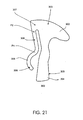
- FIG.21 illustrates a rotatable locking member 300 having a convex shaped head 302 at the end of a first arm 303, which is opposite a second arm 304 at the other end of the rotatable locking member 300.
- the rotatable locking member 300 does not have a core aperture as seen in previous embodiments of the invention.
- rotatable locking member 300 has a resilient arm 306 that is connected substantially near the top and back of the first arm 303. This point of connection 307 is substantially away from both the center of the rotatable locking member as well as the point on the resilient arm 306 where the rotatable locking member will be forced against the angled back wall of the groove.
- the groove into which the plastic rotatable locking member 300 is placed is substantially similar to the angled grooves seen in previous aspects of this embodiment in FIGs. 1 through 12 .
- rotatable locking member 300 with resilient arm 306 is initially in an open position in which the second arm 304 is projected out into the opening of a groove into which it sits, the tongue of the adjacent panel will press against the front face 305 of the second arm rotating the rotatable locking member so that the convex shaped head 302 swings forward to engage the corresponding hooked shaped groove in the tongue.
- the resilient arm 306 has a substantially straight portion 308 extending from the point of contact to some point along a portion of the length of the resilient arm and then a curved portion 309 from that point after the straight portion 308 to the end of the resilient arm.
- the curved portion presses against the rear surface of the angled groove and as the rotatable locking member is rotated towards the closed position, this curved portion 309 of the resilient arm 306 will be subject to forces and compress.
- P1 and connection point 307 may be the same point.
- a fourth embodiment of the invention is presented with reference to FIGs. 13 through 18 .
- the rotational member may be possible, given the material out of which the rotational members are made and the material out of which the flooring panel is made, for the rotational member to slide or fall out of the groove in the first panel.
- the rotational members may become dislodge or may fall out of the grooves in the panels entirely. It then becomes difficult for the installer to locate the rotational member in the product and re-insert it into the groove easily and without damaging it.
- This fourth embodiment addresses this problem, among others.
- a plastic insert member 400 is provided with a first slot portion 402 and a rotatable locking member portion 404.
- the slot portion 402 and the rotatable locking member portion 404 are connected by an S-shaped resilient coil 406.
- the entire plastic insert member 400 is a single unitary and integrated body.
- an axial extension portion 408 is complemented by an axial groove or notch 409 at the rear surface of the rotatable locking member 404.
- the slot member 402 and the rotatable locking member portion 404 are additionally connected to one another by a rib 407 located at the tip of an axial extension or portion 408 which meets the center portion of the rear surface of the rotatable locking portion 404.
- both aspects illustrated in FIGs. 13 and 14 include a number of teeth or flanges 410 at an end portion of the slot member 402 opposite the axial extension 408 which allow the slot insertion portion 402 to slide into a corresponding groove formed into the first panel but prevent the slot insertion portion 402 from sliding out, thus holding the slot member 402 firmly in place while allowing the rotatable locking member portion 404 to rotate freely.
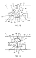
- FIG.15 illustrates the insertion member 400 of FIG.13 inserted within a primary groove 412 having a rear slot 411, a top arcuate surface 413 and a lower arcuate surface 414.
- the insertion member 400 is inserted into the groove 412 such that the slot member 402 is secured within the groove 413 via the flanges or teeth 410. This is accomplished by making the thickness of the slot insertion member 402 as measured from the tip of the teeth on opposite sides to be slightly greater than the width of the groove 413.
- the thickness of the slot insertion portion 402 may be 0.1mm thicker than the width of the opening of groove 413.
- the rotatable locking member portion 404 having a first arm 415 and a second arm 416 hangs freely via the S-shaped coil 406 which is in turn connected to the slot insertion portion 402 secured in the rear groove 413.
- the shape of the coil when it is formed determines its rest position. If the coil is formed in a wound-shape as in FIGs. 13-15 , then stretching the coil straight or in an unwound position will create tension in the coil, which tries to pull the coil back to its original shape. By contrast, if the coil is formed in a substantially straight or unwound shape (see FIG.22 below), then winding it or coiling the coil with create tension that urges it to be released to its original straightened position.
- the tongue portion 419 of the second panel 418 presses against the second arm 416 of the rotatable locking member portion 404 of the insertion member 400.
- the rotatable locking member portion 404 is pushed back against the slot member so that the axial extension 408 enters and pressed against the axial groove 409.
- the tip of the axial extension 408 pressed into the axial groove 409 becomes the point around which the rotatable locking member portion 404 rotates.
- the hooked shaped groove 421 is designed such that the leading edge 422 over the hook shaped groove 421 is slightly higher than the bottom surface 423 of the hook shaped groove 421. This allows the convex shaped head 420 to enter the hook shaped groove 421, touch the bottom surface 423 and be held in place in a horizontal direction by the slightly higher leading edge 422.
- the rotation of the rotatable locking member portion 404 occurs under tension provided by the resilient coil 406. Specifically, while the rotatable locking member rotates around the tip of the axial extension 408 pressed into the axial groove 409, the resilient coil 406 becomes uncoiled or straightened as the convex shaped head 420 rotates forward. The extension of resilient coil 406 occurs under tension, urges the rotatable locking member portion 404 to rotate back to its original open position. However, the rotatable locking member is forced to rotate towards the closed position by the force exerted by the tongue 419 against the second arm 416.
- FIG. 16 The closed position of the joint according to this aspect of this embodiment of the invention is illustrated in FIG. 16 .
- the resilient coil 406 is shown in its extended or unwound position exerting force opposing the rotation of the rotatable locking member portion 404 towards the closed position.
- the rotatable locking member portion 404 has a rear protrusion 424 whose outer surface 425 has an arcuate or curved shape. The purpose of this rear extension 424 with the arcuate outer surface 425 is to facilitate sliding of the rotatable locking member portion 404 against the surface 414 of the groove 412 as the rotatable locking member portion 404 rotates from the open position to the closed position.
- the arcuate shaped outer surface 425 provides for a smoother rotation of the rotatable locking member than would be present if the rear extension 424 were not present.
- FIGs. 15 and 16 illustrate a further aspect of the embodiment in which the rear groove 413 is not parallel to the upper surfaces of the panels 417 and 418 but is rather at an angle.
- the groove depth, angle and vertical position within the first panel 417 are selected to provide enough room above the slot member 402 and behind the rotatable locking member portion 404 into which the resilient coil member 406 can wind and unwind in the open and closed positions, respectively.
- the resilient coil 406 By allowing for greater space in this region where the resilient coil 406 will be present allows the coil to be made longer or with a variety of shapes, such as an S-shape, a zigzag or accordion shape, a bowed shape or the like. By allowing for a longer resilient coil 406, all the forces acting upon the rotatable locking member 404 are distributed along the length of the curve and not concentrated around a single point.
- the S-shape or a continuous curve is better than a zigzag shape, provided there is enough room for it in the groove, because the zigzag shape will suffer extremes of tension at the vertexes of the angles, where the portions of the accordion fold, whereas an S-shaped or other shaped continuous curve will have the forces distributed continuously along its length. This resists breakage and cracking better than a zigzag or accordion shape.
- the invention is not limited to any particular shape of coil connecting the rotatable locking member to the slotted insertion member. FIGs.
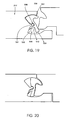
- 17 and 18 illustrate further aspects of the present embodiment in which the insertion member of a second aspect illustrated in FIG.14 is inserted into a rear groove 425 that is substantially parallel to the upper surface of the flooring and placed in substantially the center of the panel.
- the operation of the joint is substantially similar with a few notable exceptions.
- the upper groove 427 of the second panel 418 does not have a hook shape but is rather a convex shape that is substantially smooth or flat along the lower surface 429.
- the resilient coil 406 is substantially similar to that of the previous aspect illustrated in FIGs. 13 , 15 and 16 .
- the second arm 426 is not necessary for the second arm 426 to extend the entire radius of the lower half of groove from the axial extension 408 to the bottom surface 431 of the groove opening. Rather, it is sufficient that the second arm only be long enough to be engaged by the tongue 430 as it enters the groove.
- FIG.18 illustrates this aspect of this embodiment of the invention in which the insertion member is in a closed position.
- the rotatable locking member portion 404 is in the closed position with the convex shaped head 428 secured in the groove 427 and in which the tongue portion 430 is pressed against a rear arcuate surface 431 of the lower lip portion 432 of the groove.
- the tongue 430 and the second panel 418 are secured both vertically and horizontally within the groove. They are secured vertically by the presence of the convex shaped head 428 of the rotatable locking member which in turn presses against the upper arcuate surface 433 of the groove.
- the top of the rotatable locking member 404 is pressed against the upper arcuate surface 433 of the groove.
- the upper surface of the tongue 430 is pressed against the lower surface of the convex shaped head 428 and the lower arcuate surface 431 of the groove is pressed against a lower rear surface 434 of the tongue. This holds the tongue securely in place against the rotatable locking member portion 404.
- the placement of the slot portion of the slot groove 413 in the rear wall of the groove 412 is not critical provided that it provides enough room above the slot portion 402 for the resilient coil 406 to wind and unwind within that space.
- the greater the space provided the greater the length that coil may be which allows greater forces to be distributed along its length. This greater force will contribute to a more exaggerated or a more pronounced snap action when the rotatable locking member engages the groove above the tongue and enters the closed position.
- first point of contact 440 where the rear wall 441 of the tongue 419 touches or abuts the arcuate curve 414 of the groove 412. This point 440 will be referred to as the first point of contact.
- a second point of contact 443 is where the lower tip 442 of the tongue 419 presses against the second arm 416 of the rotatable locking member 404.
- a third point of contact 444 is present where the upper arcuate surface 413 touches the top of the first arm 415 of the convex shaped head 420.
- the fourth point of contact 445 is present where the raised tip 422 of the hook shaped groove 421 touches the under surface of the convex shaped head 420.
- first point of contact 440 the second point of contact 443, the third point of contact 444, and the fourth point of contact 445
- the second panel 418 is held in place in the vertical direction because any movement vertically will cause the tongue 419 to press against point 445 with greater force. That force will be transmitted through the body of the convex shaped head 420 to where the first arm 415 meets the first panel 417 at point 444. Because the points 440, 444 and 445 are in contact when the joint is in the closed position, there is no room for the second panel 418 to move in the vertical direction.
- the first point of contact 440 and the second point of contact 443 immobilize the tongue in a horizontal direction making it impossible for the tongue of the second panel to move out from the joint in a horizontal direction.
- the second panel 418 is rotate at an angle causing the rotatable locking member portion 404 to rotate back towards its original open position, thus allowing the tongue to escape from the now open groove.
- the two adjacent panels 417 and 418 may be locked so that their upper surfaces are at substantially the same plane so that they are locked relative to one another and so that there is no play in the joint, but also allowing the panels once joined to be easily separated.
- a gap 446 is provided between the convex shaped head 420 and the upper wall of the hook shaped groove 447. This gap is important because it facilitates smooth movement and rotation of the convex shaped head snapping forward into the hook shaped groove when the rotatable locking member passes from the open to the closed position. This reduces the friction, allows the joint to operate more smoothly and provides for a more audible and pronounced snapping action when the joint closes.
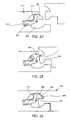
- FIGs. 19 and 20 A fifth embodiment of the present invention is illustrated in FIGs. 19 and 20 .
- this embodiment rather than an axial extension at the end of a slot member secured into a groove at the rear of a main groove in the first panel 417, this embodiment illustrates an insertion member 500 having a hooked shaped head 502, a second arm 504, a resilient arm 505 and a core aperture 506.
- the rotatable member 500 is secured in place through a protrusion 507 formed into and as part of the back wall of the groove 508. Because it is made from the core material of the first panel 517, this protrusion 507 acts as the axis of rotation around which the rotatable locking member 500 will rotate.
- the operation of the joint is substantially similar to the embodiments heretofore discussed, with the insertion member moving from an open to a closed position as the panels are joined.
- the resilient arm 505 engages the rear surface of the groove 508 underneath the protrusion 507.
- the closed position of this joint illustrated in FIG.20 is substantially similar to the closed position of the joint illustrated in FIG.4 with the exception that the rotatable locking member rotates not around the point of force of the resilient arm but rather rotates around the protrusion 507.
- FIGs. 22 through 26 A sixth embodiment is illustrated in FIGs. 22 through 26 , in which a insertion member having a rotatable portion provided a locking operation in which the rotatable member moves from a closed position, to a open position during locking, back to the closed position after locking .
- insertion member 600 is provided with a rotatable member 602 having a convex head 604.
- the insertion member 600 has a main body 605 with an arcuate groove 606 formed on an upper surface 607.
- the insertion member 600 also has a slot insertion portion 603 substantially similar to the slot portion 402 illustrated in FIG.13 .
- the slot insertion portion 603 may have one or more teeth or flanges 608 that facilitate securing the slot insertion portion 603 into a corresponding slot at the rear of a groove.
- rotatable member 602 has a single arm 609 with a rounded or blunt tip 610 shaped and sized to correspond to the arcuate groove 606 formed in the main body 605.
- the rotatable member 602 is connected to the slot member 603 via a resilient coil 611.
- the resilient coil is shown with an S-shape but it is well within the scope of the invention for the coil to have any of a variety of shapes which are flexible and able to distribute force along their length.
- the upper surface 607 is substantially flat with a rib 612 connecting the tip 610 of the rotatable member 602 to the main body 605.
- This rib provides additional support and also provide tension or resistance in addition to the tension supported by the coil 611.
- FIGs. 24 through 26 illustrate the operation of a joint according to this embodiment of the present invention using the insertion member 600 of the first aspect illustrated in FIG.22 .
- the insertion member 600 begins in the closed position in which the rotatable member 602 is rotated forward. In this position, the resilient coil 611 is at rest and the rotatable member 602 is swung forward to partially close the groove 620 formed in the first panel 617.
- the slot member 603 is secured within a slot 612 at the rear of the groove 620.
- the lower portion of the groove 620 is substantially empty; however, it is understood to be within the scope of the invention that the groove may be formed much smaller, providing only enough space as is necessary to accommodate tongue 621, rather than making the groove to have a shape substantially similar to that of FIG.15 . In addition, it is also understood to be within the scope of the invention to place the slot 612 into which the slot portion 603 will fit much lower or at a greater angle in the rear groove 620 to provide maximum space in which the coil portion 611 can move.
- the tip 622 of the tongue 621 presses against the tip of head 604 causing the rotatable member 602 to rotate around the arcuate surface 606 into which the tip 610 of the rotatable member sits.
- the coil 611 is compressed, wound or contracted to place it under greater tension.
- the tip 622 of tongue 621 is slighter higher than the lower surface of the hook shaped groove 623.
- the rotatable member 602 is able to secure the tongue and the second panel 618 in place in both a horizontal and vertical direction.
- the rotatable head will swing farther forward to close the groove providing for a deeper extension into the hook shaped groove 623 which provides greater strength and a more secure joint.
- the adjacent flooring panels are joined by lowering the panel having the tongue substantially vertically into the groove, with the adjacent panels coplanar relative to one another.
- the joints of the present invention do not require rotational installation or horizontal snap-action installation. Because of this, the use of these joints is not limited to the exterior side edges of the flooring panel.
- the rotatable locking members and insertion members can be made of any material including metal, glass, wood, plastic, composite or fiberglass, but that it is likely that they will be made of a type of plastic because plastic provides the greatest flexibility and the greatest ease of manufacturing, depending on the particular shape of rotatable locking member.
- the flooring panels may be made of medium or high density fiberboard (MDF or HDF) the flooring panels or their core material into which the tongue and grooves are formed maybe any of a variety of materials as well, including wood, particle board, chip board, or plastic.
Landscapes
- Engineering & Computer Science (AREA)
- Architecture (AREA)
- Civil Engineering (AREA)
- Structural Engineering (AREA)
- Floor Finish (AREA)
- Vehicle Body Suspensions (AREA)
- Noodles (AREA)
Claims (1)
- Panneau de sol comprenant :- un joint à enclenchement possédant un premier côté (34) définissant une première portion d'accouplement le long d'un premier côté (34), et un deuxième côté (46) définissant une deuxième portion d'accouplement le long d'un deuxième côté (46), ledit deuxième côté (46) étant opposé audit premier côté (34) ;- la première portion d'accouplement possédant une rainure substantiellement arquée (36, 276), formée dans celle-ci et s'étendant le long d'au moins une portion du premier côté (34) ;- une came rotative (10, 110, 200, 278, 300, 404, 500, 602) disposée dans la rainure (36, 276) s'étendant dans un sens longitudinal, le long d'au moins une portion du premier côté ;- la came rotative (10, 110, 200, 278, 300, 404, 500, 602) possédant une portion centrale, un premier bras (18, 118, 218, 303, 415) s'étendant radialement vers l'extérieur à partir de la portion centrale, le long d'un premier axe, un deuxième bras (22, 122, 222, 282, 304, 416, 426, 504) s'étendant radialement vers l'extérieur à partir de la portion centrale, le long d'un deuxième axe, ainsi qu'un bras résilient (24, 124, 224, 280, 306, 406, 505) ;- le premier bras (18, 118, 218, 303, 415) possédant une portion de levier (26) et une portion courbe (28, 128), la portion courbe (28, 128) s'étendant substantiellement perpendiculairement à la portion de levier (26) définissant une extrémité substantiellement en forme de crochet ;- une lèvre inférieure (42, 142, 242, 274) s'étendant vers l'extérieur à partir de la première portion d'accouplement, au-delà de la rainure (36, 276) ;- ladite deuxième portion d'accouplement possédant une langue (48, 148, 248, 270, 419, 430) s'étendant perpendiculairement à partir dudit deuxième côté (46) et s'étendant le long d'au moins une portion du deuxième côté, et définissant une rainure substantiellement concave (50, 150, 250) le long d'une surface inférieure, destinée à recevoir ladite lèvre inférieure (42, 142, 242, 274) ;- ladite langue (48, 148, 248, 270, 419, 430, 621) possédant une face substantiellement verticale, au moins aussi longue que la distance entre l'extrémité en forme de crochet du premier bras (18, 118, 218, 303, 415) et l'extrémité du deuxième bras (22, 122, 222, 282, 304, 416, 426, 504) ;- ladite deuxième portion d'accouplement définissant en outre une rainure de verrouillage (52, 152, 252, 288, 427, 623) formée dans celle-ci, au-dessus de la langue (48, 148, 248, 270, 419, 430, 621), pour recevoir l'extrémité en forme de crochet du premier bras (18, 118, 218, 303, 415) de la came rotative (10, 110, 200, 278, 300, 404, 500, 602) ;caractérisé en ce que- le bras résilient (24, 124, 224, 280, 306, 406, 505) s'étend radialement vers l'extérieur à partir de la portion centrale, le long d'un troisième axe, tout en étant disposé à une certaine distance du deuxième bras (22, 122, 222, 282, 304, 416, 426, 504), définie par un angle prédéterminé ;- le deuxième bras (22, 122, 222, 282, 304, 416, 426, 504) et le bras résilient (24, 124, 224, 280, 306, 406, 505) peuvent être courbés l'un vers l'autre, pour créer une force d'activation,- dans lequel la force d'activation pousse le deuxième bras (22, 122, 222, 282, 304, 416, 426, 504) vers la langue (48, 148, 248, 270, 419, 430, 621), de manière à ce que la langue (48, 148, 248, 270, 419, 430, 621) avance dans une direction, vers la première portion d'accouplement, et la portion courbe (28, 128) du premier bras (18, 118, 303, 415) se déplace dans une position d'accouplement avec la rainure de verrouillage (52, 152, 252), fournissant ainsi une connexion de verrouillage serrée.
Applications Claiming Priority (1)
| Application Number | Priority Date | Filing Date | Title |
|---|---|---|---|
| US11/878,153 US7726088B2 (en) | 2007-07-20 | 2007-07-20 | Flooring system |
Publications (3)
| Publication Number | Publication Date |
|---|---|
| EP2017403A2 EP2017403A2 (fr) | 2009-01-21 |
| EP2017403A3 EP2017403A3 (fr) | 2009-04-08 |
| EP2017403B1 true EP2017403B1 (fr) | 2011-03-23 |
Family
ID=39926554
Family Applications (1)
| Application Number | Title | Priority Date | Filing Date |
|---|---|---|---|
| EP08013108A Active EP2017403B1 (fr) | 2007-07-20 | 2008-07-21 | Système de plancher |
Country Status (7)
| Country | Link |
|---|---|
| US (1) | US7726088B2 (fr) |
| EP (1) | EP2017403B1 (fr) |
| CN (1) | CN101368440B (fr) |
| AT (1) | ATE503060T1 (fr) |
| CA (1) | CA2638088C (fr) |
| DE (1) | DE602008005674D1 (fr) |
| WO (1) | WO2009013590A2 (fr) |
Cited By (1)
| Publication number | Priority date | Publication date | Assignee | Title |
|---|---|---|---|---|
| US8997430B1 (en) | 2010-04-15 | 2015-04-07 | Spanolux N.V.-Div. Balterio | Floor panel assembly |
Families Citing this family (125)
| Publication number | Priority date | Publication date | Assignee | Title |
|---|---|---|---|---|
| SE9500810D0 (sv) | 1995-03-07 | 1995-03-07 | Perstorp Flooring Ab | Golvplatta |
| US7131242B2 (en) | 1995-03-07 | 2006-11-07 | Pergo (Europe) Ab | Flooring panel or wall panel and use thereof |
| US7992358B2 (en) | 1998-02-04 | 2011-08-09 | Pergo AG | Guiding means at a joint |
| SE514645C2 (sv) | 1998-10-06 | 2001-03-26 | Perstorp Flooring Ab | Golvbeläggningsmaterial innefattande skivformiga golvelement avsedda att sammanfogas av separata sammanfogningsprofiler |
| SE518184C2 (sv) * | 2000-03-31 | 2002-09-03 | Perstorp Flooring Ab | Golvbeläggningsmaterial innefattande skivformiga golvelement vilka sammanfogas med hjälp av sammankopplingsorgan |
| CA2481329C (fr) | 2002-04-03 | 2012-01-10 | Darko Pervan | Systeme de blocage mecanique pour plancher flottant |
| US7454875B2 (en) | 2004-10-22 | 2008-11-25 | Valinge Aluminium Ab | Mechanical locking system for floor panels |
| DE602004010914T3 (de) | 2004-10-22 | 2011-07-07 | Välinge Innovation AB | Satz von Fussbodenpaneelen |
| US7841144B2 (en) | 2005-03-30 | 2010-11-30 | Valinge Innovation Ab | Mechanical locking system for panels and method of installing same |
| US8061104B2 (en) | 2005-05-20 | 2011-11-22 | Valinge Innovation Ab | Mechanical locking system for floor panels |
| SE530653C2 (sv) | 2006-01-12 | 2008-07-29 | Vaelinge Innovation Ab | Fuktsäker golvskiva samt golv med ett elastiskt ytskikt omfattande ett dekorativt spår |
| TR201812068T4 (tr) * | 2006-04-14 | 2018-09-21 | Yekalon Ind Inc | Zemin paneli ve zemin kaplama sistemi. |
| US8689512B2 (en) | 2006-11-15 | 2014-04-08 | Valinge Innovation Ab | Mechanical locking of floor panels with vertical folding |
| US11725394B2 (en) | 2006-11-15 | 2023-08-15 | Välinge Innovation AB | Mechanical locking of floor panels with vertical folding |
| SE531111C2 (sv) | 2006-12-08 | 2008-12-23 | Vaelinge Innovation Ab | Mekanisk låsning av golvpaneler |
| US8220217B2 (en) | 2007-07-20 | 2012-07-17 | Innovaris Ag | Flooring system |
| DE102007042250B4 (de) * | 2007-09-06 | 2010-04-22 | Flooring Technologies Ltd. | Einrichtung zur Verbindung und Verriegelung zweier Bauplatten, insbesondere Fussbodenpaneele |
| DE102007043308B4 (de) * | 2007-09-11 | 2009-12-03 | Flooring Technologies Ltd. | Einrichtung zur Verbindung und Verriegelung zweier Bauplatten, insbesondere Fussbodenpaneele |
| CN101910528B (zh) | 2007-11-07 | 2012-07-25 | 瓦林格创新股份有限公司 | 通过竖直卡合折叠实现的地板镶板的机械锁定和连接这种镶板的安装方法 |
| US8353140B2 (en) | 2007-11-07 | 2013-01-15 | Valinge Innovation Ab | Mechanical locking of floor panels with vertical snap folding |
| BE1018600A5 (nl) | 2007-11-23 | 2011-04-05 | Flooring Ind Ltd Sarl | Vloerpaneel. |
| RU2485265C2 (ru) | 2008-01-31 | 2013-06-20 | Велинге Инновейшн Белджиум Бвба | Механический фиксатор панелей пола, способы установки и разборки панелей, способ и оборудование для создания запирающего устройства, способ соединения смещаемого шипа с панелью и заготовка шипа |
| US8505257B2 (en) | 2008-01-31 | 2013-08-13 | Valinge Innovation Ab | Mechanical locking of floor panels |
| US20090223144A1 (en) * | 2008-02-02 | 2009-09-10 | Leahy Charles H | Methods & systems for modular buildings |
| US8112967B2 (en) | 2008-05-15 | 2012-02-14 | Valinge Innovation Ab | Mechanical locking of floor panels |
| DE102008047098B3 (de) * | 2008-09-12 | 2010-04-08 | Guido Schulte | Fußbodenbelag |
| DE102008047099B4 (de) * | 2008-09-12 | 2010-05-12 | Guido Schulte | Fußbodenbelag |
| BE1018389A3 (nl) * | 2008-12-17 | 2010-10-05 | Unilin Bvba | Samengesteld element, meerlagige plaat en paneelvormig element voor het vormen van zulk samengesteld element. |
| BE1018627A5 (nl) * | 2009-01-16 | 2011-05-03 | Flooring Ind Ltd Sarl | Vloerpaneel. |
| UA103515C2 (ru) | 2009-01-30 | 2013-10-25 | Велинге Инновейшн Аб | Механическая блокировка панелей пола и заготовка шпунтов |
| CH700513A2 (de) * | 2009-03-10 | 2010-09-15 | Innovaris Ag | Paneele. |
| EP2236694A1 (fr) * | 2009-03-25 | 2010-10-06 | Spanolux N.V.- DIV. Balterio | Système de fixation et panneau |
| BE1018712A3 (nl) * | 2009-04-09 | 2011-07-05 | Flooring Ind Ltd Sarl | Vloerpanelen. |
| US8205407B2 (en) * | 2009-04-15 | 2012-06-26 | Genova Michael C | Modular decking system |
| BE1018728A3 (nl) * | 2009-04-22 | 2011-07-05 | Flooring Ind Ltd Sarl | Vloerpaneel. |
| DE102009022483A1 (de) * | 2009-05-25 | 2010-12-02 | Pergo (Europe) Ab | Set von Paneelen, insbesondere von Fußbodenpaneelen |
| DE102009034902B4 (de) * | 2009-07-27 | 2015-10-01 | Guido Schulte | Belag aus mechanisch miteinander verbindbaren Paneelen |
| DE102009048050B3 (de) * | 2009-10-02 | 2011-01-20 | Guido Schulte | Belag aus mechanischen miteinander verbindbaren Elementen |
| EP3561197B1 (fr) * | 2009-12-22 | 2023-03-15 | Flooring Industries Limited, SARL | Panneau |
| EP3702549B1 (fr) * | 2010-01-12 | 2023-05-10 | Välinge Innovation AB | Jeu de panneaux de sol |
| WO2011085825A1 (fr) * | 2010-01-14 | 2011-07-21 | Spanolux N.V.- Div. Balterio | Ensemble de panneaux de plancher et panneau de plancher destiné à être utilisé dans celui-ci |
| DE102010004717A1 (de) | 2010-01-15 | 2011-07-21 | Pergo (Europe) Ab | Set aus Paneelen umfassend Halteprofile mit einem separaten Clip sowie Verfahren zum Einbringen des Clips |
| EP2531667B1 (fr) * | 2010-02-04 | 2020-08-26 | Välinge Innovation AB | Système de verrouillage mécanique pour panneaux de plancher et languette pour celui-ci |
| KR101245963B1 (ko) * | 2010-03-02 | 2013-03-21 | 오광석 | 바닥재 및 이에 이용되는 회전체 |
| BE1019331A5 (nl) | 2010-05-10 | 2012-06-05 | Flooring Ind Ltd Sarl | Vloerpaneel en werkwijzen voor het vervaardigen van vloerpanelen. |
| WO2011141043A1 (fr) | 2010-05-10 | 2011-11-17 | Pergo AG | Ensemble de panneaux |
| PL2575542T3 (pl) | 2010-06-03 | 2021-09-06 | Unilin, Bv | Element złożony i połączenie narożne zastosowane w nim |
| US8591696B2 (en) | 2010-11-17 | 2013-11-26 | Pergo (Europe) Ab | Method for manufacturing a surface element |
| CN102619323A (zh) * | 2011-01-27 | 2012-08-01 | 张国平 | 塑性材料的倒钩型锁扣地板 |
| US8806832B2 (en) | 2011-03-18 | 2014-08-19 | Inotec Global Limited | Vertical joint system and associated surface covering system |
| EP2520737B1 (fr) * | 2011-05-03 | 2017-03-22 | Barlinek S.A. | Panneau de construction doté d'un dispositif de liaison avec au moins un autre panneau de construction sur un sous-sol |
| UA109938C2 (uk) | 2011-05-06 | 2015-10-26 | Механічна фіксуюча система для будівельних панелей | |
| BE1020044A5 (nl) | 2011-06-29 | 2013-04-02 | Unilin Bvba | Lade, ladeconstructie en werkwijze voor het vervaardigen van een lade. |
| UA114715C2 (uk) | 2011-07-05 | 2017-07-25 | Сералок Інновейшн Аб | Механічна фіксація панелей настилу підлоги до язичка з нанесеним шаром клею |
| US9725912B2 (en) | 2011-07-11 | 2017-08-08 | Ceraloc Innovation Ab | Mechanical locking system for floor panels |
| US8650826B2 (en) | 2011-07-19 | 2014-02-18 | Valinge Flooring Technology Ab | Mechanical locking system for floor panels |
| DE102012102339A1 (de) * | 2011-07-29 | 2013-01-31 | Hamberger Industriewerke Gmbh | Verbindung für elastische oder plattenförmige Bauelemente, Profilschieber und Fußbodenbelag |
| JP6184953B2 (ja) * | 2011-08-15 | 2017-08-23 | セラロック、イノベーション、アクチボラグ | フロアパネルの機械的固定システム |
| US8763340B2 (en) | 2011-08-15 | 2014-07-01 | Valinge Flooring Technology Ab | Mechanical locking system for floor panels |
| US8769905B2 (en) | 2011-08-15 | 2014-07-08 | Valinge Flooring Technology Ab | Mechanical locking system for floor panels |
| US8857126B2 (en) | 2011-08-15 | 2014-10-14 | Valinge Flooring Technology Ab | Mechanical locking system for floor panels |
| DE102011119889A1 (de) * | 2011-11-28 | 2013-05-29 | Falquon Gmbh | System bestehend aus zwei miteinander verbundenen und verriegelten Bauplatten mit einem Verriegelungselement |
| DE102011056494A1 (de) * | 2011-12-15 | 2013-06-20 | Pergo (Europe) Ab | Set aus Paneelen mit Clip |
| BE1020433A3 (nl) * | 2012-01-05 | 2013-10-01 | Flooring Ind Ltd Sarl | Paneel. |
| US8596013B2 (en) | 2012-04-04 | 2013-12-03 | Valinge Innovation Ab | Building panel with a mechanical locking system |
| US9216541B2 (en) | 2012-04-04 | 2015-12-22 | Valinge Innovation Ab | Method for producing a mechanical locking system for building panels |
| CN103541554B (zh) * | 2012-07-17 | 2016-04-06 | 上海汽车改装厂有限公司 | 用于工作机械的作业杆及具有该作业杆的工作机械 |
| EP2923012B1 (fr) | 2012-11-22 | 2019-10-16 | Ceraloc Innovation AB | Système de verrouillage mécanique pour panneaux de plancher |
| DE102013101756A1 (de) * | 2012-11-30 | 2014-06-05 | Hamberger Industriewerke Gmbh | Verbindung und Verriegelungselement |
| EP2946047B1 (fr) * | 2013-01-11 | 2019-03-13 | Flooring Industries Limited, SARL | Panneau de plancher permettant de former un revêtement de sol |
| US9194134B2 (en) | 2013-03-08 | 2015-11-24 | Valinge Innovation Ab | Building panels provided with a mechanical locking system |
| BE1021833B1 (nl) * | 2013-05-30 | 2016-01-21 | Flooring Industries Limited Sarl | Paneel |
| EA032211B1 (ru) | 2013-06-27 | 2019-04-30 | Велинге Инновейшн Аб | Комплект строительных панелей с механической запирающей системой |
| CN105358777B (zh) | 2013-07-09 | 2018-03-02 | 塞拉洛克创新股份有限公司 | 用于地板镶板的机械锁定系统 |
| WO2015038059A1 (fr) | 2013-09-16 | 2015-03-19 | Välinge Innovation AB | Produit assemblé et procédé d'assemblage du produit assemblé |
| US9726210B2 (en) | 2013-09-16 | 2017-08-08 | Valinge Innovation Ab | Assembled product and a method of assembling the product |
| CA2926336C (fr) | 2013-10-25 | 2022-07-05 | Floor Iptech Ab | Systeme de verrouillage mecanique pour lattes de plancher |
| AU2014376416B2 (en) | 2014-01-10 | 2019-08-29 | Valinge Innovation Ab | A furniture panel |
| US9714672B2 (en) | 2014-01-10 | 2017-07-25 | Valinge Innovation Ab | Panels comprising a mechanical locking device and an assembled product comprising the panels |
| US9260870B2 (en) | 2014-03-24 | 2016-02-16 | Ivc N.V. | Set of mutually lockable panels |
| US10280627B2 (en) | 2014-03-24 | 2019-05-07 | Flooring Industries Limited, Sarl | Set of mutually lockable panels |
| EP3851684A1 (fr) | 2014-05-09 | 2021-07-21 | Välinge Innovation AB | Système de verrouillage mécanique pour panneaux de construction |
| US10246883B2 (en) | 2014-05-14 | 2019-04-02 | Valinge Innovation Ab | Building panel with a mechanical locking system |
| WO2015174914A1 (fr) | 2014-05-14 | 2015-11-19 | Välinge Innovation AB | Panneau de construction a systeme de verrouillage mecanique |
| BE1021929B1 (nl) | 2014-07-04 | 2016-01-27 | Unilin Bvba | Vloerpaneel |
| DE102014112527A1 (de) * | 2014-09-01 | 2016-03-03 | Guido Schulte | Mechanische Verbindung für Paneele und Verfahren zur Montage einer Verriegelungsfeder in einem Paneel |
| DE102014112529A1 (de) * | 2014-09-01 | 2016-03-03 | Guido Schulte | Mechanische Verbindung für Paneele und Verfahren zur Montage einer Verriegelungsfeder in einem Paneel |
| EP3224427B1 (fr) | 2014-11-27 | 2019-09-11 | Välinge Innovation AB | Jeu de panneaux de plancher avec système de verrouillage mécanique |
| BR112017012422B1 (pt) | 2014-12-19 | 2022-11-08 | Vãlinge Innovation Ab | Conjunto de painéis compreendendo um dispositivo de travamento mecânico |
| WO2016171607A1 (fr) | 2015-04-21 | 2016-10-27 | Välinge Innovation AB | Panneau à coulisse |
| BR112017021806A2 (pt) | 2015-04-30 | 2018-07-10 | Välinge Innovation AB | painel com um dispositivo de fixação |
| US10448739B2 (en) | 2015-09-22 | 2019-10-22 | Valinge Innovation Ab | Panels comprising a mechanical locking device and an assembled product comprising the panels |
| CN108368866B (zh) | 2015-12-03 | 2020-09-25 | 瓦林格创新股份有限公司 | 包括机械锁定装置的镶板和包括所述镶板的组装产品 |
| DE102015121761A1 (de) * | 2015-12-14 | 2017-06-14 | Guido Schulte | Mechanische Verbindung für Paneele |
| CA3011561A1 (fr) | 2016-01-26 | 2017-08-03 | Valinge Innovation Ab | Panneaux comprenant un dispositif de verrouillage mecanique et produit assemble comportant les panneaux |
| KR20180109957A (ko) | 2016-02-04 | 2018-10-08 | 뵈린게 이노베이션 에이비이 | 조립된 제품을 위한 패널들의 세트 |
| CN108603523B (zh) | 2016-02-09 | 2020-05-26 | 瓦林格创新股份有限公司 | 用于提供拆卸凹槽的元件和方法 |
| KR20180113546A (ko) | 2016-02-09 | 2018-10-16 | 뵈린게 이노베이션 에이비이 | 3개의 패널-형상 요소들의 세트 |
| CA3011421C (fr) | 2016-02-15 | 2024-01-16 | Valinge Innovation Ab | Procede pour former un panneau pour un produit de mobilier |
| BE1024157B1 (nl) * | 2016-04-25 | 2017-11-24 | Flooring Industries Limited, Sarl | Set van vloerpanelen en werkwijze voor het installeren van deze set van vloerpanelen. |
| BR112019007619B1 (pt) | 2016-10-27 | 2023-02-14 | Välinge Innovation AB | Conjunto de painéis com um dispositivo de travamento mecânico |
| BE1024734B1 (nl) * | 2016-11-10 | 2018-06-19 | Ivc Bvba | Vloerpaneel en werkwijze voor het vervaardigen van een vloerpaneel |
| WO2018172955A2 (fr) * | 2017-03-21 | 2018-09-27 | Flooring Industries Limited, Sarl | Panneau de plancher pour la formation d'un revêtement de sol |
| MY196739A (en) | 2017-05-15 | 2023-05-03 | Valinge Innovation Ab | Elements and a locking device for an assembled product |
| HUE071513T2 (hu) * | 2017-07-18 | 2025-09-28 | Lignum Tech Ag | Panelek eltávolítható kiálló peremmel fal-mennyezet- vagy padló-burkolatokhoz |
| CN107558691A (zh) * | 2017-10-25 | 2018-01-09 | 浙江新远见材料科技股份有限公司 | 一种稳定插接地板 |
| CN111630281B (zh) | 2017-12-22 | 2022-08-16 | 瓦林格创新股份有限公司 | 用于家具产品的镶板组、镶板组的组装方法和锁定装置 |
| WO2019125292A1 (fr) | 2017-12-22 | 2019-06-27 | Välinge Innovation AB | Ensemble de panneaux, leur procédé d'assemblage et dispositif de verrouillage pour un produit de mobilier |
| CN111629889B (zh) * | 2018-01-22 | 2023-06-13 | 伊诺瓦默公司 | 用于制造塑料制覆盖面板的方法和以此方式生产的面板 |
| MY204146A (en) | 2018-03-23 | 2024-08-09 | Vlinge Innovation Ab | Panels comprising a mechanical locking device and an assembled product comprising the panels |
| CA3096995A1 (fr) | 2018-04-18 | 2019-10-24 | Valinge Innovation Ab | Ensemble de panneaux comprenant un dispositif de verrouillage mecanique |
| CN112262265B (zh) | 2018-04-18 | 2022-12-20 | 瓦林格创新股份有限公司 | 对称榫舌和t形交叉组件 |
| PL3781823T3 (pl) | 2018-04-18 | 2024-06-10 | Välinge Innovation AB | Zestaw paneli z mechanicznym urządzeniem blokującym |
| EP3781824B1 (fr) | 2018-04-18 | 2024-04-10 | Välinge Innovation AB | Ensemble de panneaux avec un dispositif de verrouillage mécanique |
| US11614114B2 (en) | 2018-04-19 | 2023-03-28 | Valinge Innovation Ab | Panels for an assembled product |
| CN112424432B (zh) | 2018-06-13 | 2022-11-22 | 塞拉洛克创新股份有限公司 | 具有连接系统的地板系统和相关连接装置 |
| EP4410151A3 (fr) | 2018-08-30 | 2024-09-04 | Välinge Innovation AB | Ensemble de panneaux avec un dispositif de verrouillage mécanique |
| AU2019421529B2 (en) | 2019-01-10 | 2025-05-22 | Välinge Innovation AB | Set of panels that can be vertically unlocked, a method and a device therefore |
| BE1027032B1 (nl) * | 2019-02-07 | 2020-09-07 | Flooring Ind Ltd Sarl | Paneel en bekleding gevormd met dergelijke panelen |
| US10704267B1 (en) | 2019-03-29 | 2020-07-07 | G-Con Manufacturing, Inc. | One leg floorboard |
| CN114616377B (zh) | 2019-11-07 | 2024-07-05 | 利格朗木业技术公司 | 具有可拆卸的突出唇部的用于墙体覆盖物、天花板覆盖物或地板覆盖物的面板 |
| CN111042477A (zh) * | 2019-11-25 | 2020-04-21 | 董烈群 | 一种地板固定组件 |
| DE102019134858A1 (de) * | 2019-12-18 | 2021-06-24 | Windmöller Gmbh | Fußbodenpaneel mit separatem Clip für die vertikale Verriegelung |
| GB2599732B (en) * | 2020-10-12 | 2023-05-17 | Cap Trac Ltd | Flooring element |
| GB2617817B (en) * | 2022-03-08 | 2025-01-01 | Jonathan Ardern Fergus | Releasable connection means |
Family Cites Families (25)
| Publication number | Priority date | Publication date | Assignee | Title |
|---|---|---|---|---|
| US3309115A (en) * | 1964-03-16 | 1967-03-14 | Alfred C Langer | Mechanism for removably securing panels |
| US3392497A (en) * | 1966-10-21 | 1968-07-16 | Delron Company Inc | Modular enclosure with clamp joined panels |
| US3572224A (en) * | 1968-10-14 | 1971-03-23 | Kaiser Aluminium Chem Corp | Load supporting plank system |
| US3528690A (en) * | 1969-08-06 | 1970-09-15 | Alfred C Langer | Fastener |
| FR2079914A5 (fr) * | 1970-02-17 | 1971-11-12 | Cegebat Gp | |
| US3712653A (en) * | 1971-05-10 | 1973-01-23 | Norco Inc | Eccentric-actuated hook-type fastening device |
| US3859000A (en) * | 1972-03-30 | 1975-01-07 | Reynolds Metals Co | Road construction and panel for making same |
| US4020613A (en) * | 1975-07-02 | 1977-05-03 | Reynolds Frank L | Fastener |
| US4223500A (en) * | 1978-05-10 | 1980-09-23 | Clark Howard K | Insulation molded, load bearing, prefabricated panels |
| US4417430A (en) * | 1981-03-13 | 1983-11-29 | Standard Keil Hardware Manufacturing Co. | Direct drive positive locking panel fastener |
| US4512122A (en) * | 1982-05-03 | 1985-04-23 | Kason Industries Inc. | Panel fastener system |
| US4655013A (en) * | 1985-01-30 | 1987-04-07 | Ritland Norman A | Prefabricated modular building and method of assembly |
| US5155960A (en) * | 1988-03-29 | 1992-10-20 | Indal Furniture Systems A Division Of Indal Limited | Cam action connector for joining furniture panels |
| US5424118A (en) * | 1994-01-25 | 1995-06-13 | Mid-South Industries, Inc. | Interlocking insulative panel construction |
| US6299224B1 (en) * | 1999-09-01 | 2001-10-09 | Kason Industries, Inc. | Panel fastener |
| SE518184C2 (sv) * | 2000-03-31 | 2002-09-03 | Perstorp Flooring Ab | Golvbeläggningsmaterial innefattande skivformiga golvelement vilka sammanfogas med hjälp av sammankopplingsorgan |
| DE20304761U1 (de) * | 2003-03-24 | 2004-04-08 | Kronotec Ag | Einrichtung zum Verbinden von Bauplatten, insbesondere Bodenpaneele |
| US7841144B2 (en) * | 2005-03-30 | 2010-11-30 | Valinge Innovation Ab | Mechanical locking system for panels and method of installing same |
| US20070044411A1 (en) * | 2005-05-09 | 2007-03-01 | Meredith Walter D | Panel structures |
| SE529076C2 (sv) * | 2005-07-11 | 2007-04-24 | Pergo Europ Ab | En fog till paneler |
| CN1757856A (zh) * | 2005-11-11 | 2006-04-12 | 圣象实业(深圳)有限公司 | 一种具条状扣件的可相互锁合的板材 |
| US8689512B2 (en) * | 2006-11-15 | 2014-04-08 | Valinge Innovation Ab | Mechanical locking of floor panels with vertical folding |
| SE531111C2 (sv) * | 2006-12-08 | 2008-12-23 | Vaelinge Innovation Ab | Mekanisk låsning av golvpaneler |
| DE102007042250B4 (de) * | 2007-09-06 | 2010-04-22 | Flooring Technologies Ltd. | Einrichtung zur Verbindung und Verriegelung zweier Bauplatten, insbesondere Fussbodenpaneele |
| BE1018600A5 (nl) * | 2007-11-23 | 2011-04-05 | Flooring Ind Ltd Sarl | Vloerpaneel. |
-
2007
- 2007-07-20 US US11/878,153 patent/US7726088B2/en active Active
-
2008
- 2008-07-18 WO PCT/IB2008/001886 patent/WO2009013590A2/fr not_active Ceased
- 2008-07-18 CA CA2638088A patent/CA2638088C/fr active Active
- 2008-07-21 CN CN2008102154102A patent/CN101368440B/zh active Active
- 2008-07-21 DE DE602008005674T patent/DE602008005674D1/de active Active
- 2008-07-21 AT AT08013108T patent/ATE503060T1/de not_active IP Right Cessation
- 2008-07-21 EP EP08013108A patent/EP2017403B1/fr active Active
Cited By (2)
| Publication number | Priority date | Publication date | Assignee | Title |
|---|---|---|---|---|
| US8997430B1 (en) | 2010-04-15 | 2015-04-07 | Spanolux N.V.-Div. Balterio | Floor panel assembly |
| US9476208B2 (en) | 2010-04-15 | 2016-10-25 | Spanolux N.V.—Div. Balterio | Floor panel assembly |
Also Published As
| Publication number | Publication date |
|---|---|
| CN101368440B (zh) | 2012-01-11 |
| EP2017403A2 (fr) | 2009-01-21 |
| WO2009013590A3 (fr) | 2009-05-07 |
| CA2638088A1 (fr) | 2009-01-20 |
| CA2638088C (fr) | 2011-03-29 |
| ATE503060T1 (de) | 2011-04-15 |
| CN101368440A (zh) | 2009-02-18 |
| WO2009013590A2 (fr) | 2009-01-29 |
| EP2017403A3 (fr) | 2009-04-08 |
| US7726088B2 (en) | 2010-06-01 |
| DE602008005674D1 (de) | 2011-05-05 |
| US20090019806A1 (en) | 2009-01-22 |
Similar Documents
| Publication | Publication Date | Title |
|---|---|---|
| EP2017403B1 (fr) | Système de plancher | |
| EP2230365B1 (fr) | Système de plancher | |
| JP5399261B2 (ja) | フロアパネルの機械的係止 | |
| US10233653B2 (en) | Flooring material | |
| CN101684685B (zh) | 具有柔性舌榫的地板镶板的机械锁定 | |
| EP2524091B1 (fr) | Ensemble de panneaux de plancher | |
| US8857126B2 (en) | Mechanical locking system for floor panels | |
| CZ304981B6 (cs) | Podlahový systém a podlahové prkno pro provedení podlahového systému | |
| CN103703197B (zh) | 建筑镶板 | |
| US20100058702A1 (en) | Floor panel with coupling devices | |
| WO2008008016A1 (fr) | système de verrouillage coMPRenant un verrou à combinaison pour panneaux | |
| US8082717B2 (en) | Panel, in particular floor panel | |
| EP3655598B1 (fr) | Panneaux dotés d'une lèvre saillante détachable pour des revêtements destinés à être posés sur des murs, des plafonds ou des sols | |
| EP4055236B1 (fr) | Panneaux pourvus d'une lèvre saillante détachable pour revêtements muraux, de plafond ou de sol | |
| EP2813639B1 (fr) | Matériau de plancher comprenant des éléments de plancher joints par des éléments de liaison | |
| EA043364B1 (ru) | Панели с выполненной с возможностью отделения выступающей закраиной для настенных, потолочных или напольных покрытий |
Legal Events
| Date | Code | Title | Description |
|---|---|---|---|
| PUAI | Public reference made under article 153(3) epc to a published international application that has entered the european phase |
Free format text: ORIGINAL CODE: 0009012 |
|
| AK | Designated contracting states |
Kind code of ref document: A2 Designated state(s): AT BE BG CH CY CZ DE DK EE ES FI FR GB GR HR HU IE IS IT LI LT LU LV MC MT NL NO PL PT RO SE SI SK TR |
|
| AX | Request for extension of the european patent |
Extension state: AL BA MK RS |
|
| PUAL | Search report despatched |
Free format text: ORIGINAL CODE: 0009013 |
|
| AK | Designated contracting states |
Kind code of ref document: A3 Designated state(s): AT BE BG CH CY CZ DE DK EE ES FI FR GB GR HR HU IE IS IT LI LT LU LV MC MT NL NO PL PT RO SE SI SK TR |
|
| AX | Request for extension of the european patent |
Extension state: AL BA MK RS |
|
| 17P | Request for examination filed |
Effective date: 20091001 |
|
| 17Q | First examination report despatched |
Effective date: 20091028 |
|
| AKX | Designation fees paid |
Designated state(s): AT BE BG CH CY CZ DE DK EE ES FI FR GB GR HR HU IE IS IT LI LT LU LV MC MT NL NO PL PT RO SE SI SK TR |
|
| GRAP | Despatch of communication of intention to grant a patent |
Free format text: ORIGINAL CODE: EPIDOSNIGR1 |
|
| GRAS | Grant fee paid |
Free format text: ORIGINAL CODE: EPIDOSNIGR3 |
|
| GRAA | (expected) grant |
Free format text: ORIGINAL CODE: 0009210 |
|
| AK | Designated contracting states |
Kind code of ref document: B1 Designated state(s): AT BE BG CH CY CZ DE DK EE ES FI FR GB GR HR HU IE IS IT LI LT LU LV MC MT NL NO PL PT RO SE SI SK TR |
|
| REG | Reference to a national code |
Ref country code: GB Ref legal event code: FG4D |
|
| REG | Reference to a national code |
Ref country code: CH Ref legal event code: EP |
|
| REG | Reference to a national code |
Ref country code: IE Ref legal event code: FG4D |
|
| REF | Corresponds to: |
Ref document number: 602008005674 Country of ref document: DE Date of ref document: 20110505 Kind code of ref document: P |
|
| REG | Reference to a national code |
Ref country code: DE Ref legal event code: R096 Ref document number: 602008005674 Country of ref document: DE Effective date: 20110505 |
|
| REG | Reference to a national code |
Ref country code: NL Ref legal event code: VDEP Effective date: 20110323 |
|
| PG25 | Lapsed in a contracting state [announced via postgrant information from national office to epo] |
Ref country code: HR Free format text: LAPSE BECAUSE OF FAILURE TO SUBMIT A TRANSLATION OF THE DESCRIPTION OR TO PAY THE FEE WITHIN THE PRESCRIBED TIME-LIMIT Effective date: 20110323 Ref country code: GR Free format text: LAPSE BECAUSE OF FAILURE TO SUBMIT A TRANSLATION OF THE DESCRIPTION OR TO PAY THE FEE WITHIN THE PRESCRIBED TIME-LIMIT Effective date: 20110624 Ref country code: SE Free format text: LAPSE BECAUSE OF FAILURE TO SUBMIT A TRANSLATION OF THE DESCRIPTION OR TO PAY THE FEE WITHIN THE PRESCRIBED TIME-LIMIT Effective date: 20110323 Ref country code: LV Free format text: LAPSE BECAUSE OF FAILURE TO SUBMIT A TRANSLATION OF THE DESCRIPTION OR TO PAY THE FEE WITHIN THE PRESCRIBED TIME-LIMIT Effective date: 20110323 Ref country code: LT Free format text: LAPSE BECAUSE OF FAILURE TO SUBMIT A TRANSLATION OF THE DESCRIPTION OR TO PAY THE FEE WITHIN THE PRESCRIBED TIME-LIMIT Effective date: 20110323 |
|
| LTIE | Lt: invalidation of european patent or patent extension |
Effective date: 20110323 |
|
| PG25 | Lapsed in a contracting state [announced via postgrant information from national office to epo] |
Ref country code: NO Free format text: LAPSE BECAUSE OF FAILURE TO SUBMIT A TRANSLATION OF THE DESCRIPTION OR TO PAY THE FEE WITHIN THE PRESCRIBED TIME-LIMIT Effective date: 20110623 Ref country code: CY Free format text: LAPSE BECAUSE OF FAILURE TO SUBMIT A TRANSLATION OF THE DESCRIPTION OR TO PAY THE FEE WITHIN THE PRESCRIBED TIME-LIMIT Effective date: 20110323 Ref country code: FI Free format text: LAPSE BECAUSE OF FAILURE TO SUBMIT A TRANSLATION OF THE DESCRIPTION OR TO PAY THE FEE WITHIN THE PRESCRIBED TIME-LIMIT Effective date: 20110323 Ref country code: SI Free format text: LAPSE BECAUSE OF FAILURE TO SUBMIT A TRANSLATION OF THE DESCRIPTION OR TO PAY THE FEE WITHIN THE PRESCRIBED TIME-LIMIT Effective date: 20110323 Ref country code: AT Free format text: LAPSE BECAUSE OF FAILURE TO SUBMIT A TRANSLATION OF THE DESCRIPTION OR TO PAY THE FEE WITHIN THE PRESCRIBED TIME-LIMIT Effective date: 20110323 Ref country code: BG Free format text: LAPSE BECAUSE OF FAILURE TO SUBMIT A TRANSLATION OF THE DESCRIPTION OR TO PAY THE FEE WITHIN THE PRESCRIBED TIME-LIMIT Effective date: 20110623 |
|
| PG25 | Lapsed in a contracting state [announced via postgrant information from national office to epo] |
Ref country code: BE Free format text: LAPSE BECAUSE OF FAILURE TO SUBMIT A TRANSLATION OF THE DESCRIPTION OR TO PAY THE FEE WITHIN THE PRESCRIBED TIME-LIMIT Effective date: 20110323 |
|
| PG25 | Lapsed in a contracting state [announced via postgrant information from national office to epo] |
Ref country code: PT Free format text: LAPSE BECAUSE OF FAILURE TO SUBMIT A TRANSLATION OF THE DESCRIPTION OR TO PAY THE FEE WITHIN THE PRESCRIBED TIME-LIMIT Effective date: 20110725 Ref country code: EE Free format text: LAPSE BECAUSE OF FAILURE TO SUBMIT A TRANSLATION OF THE DESCRIPTION OR TO PAY THE FEE WITHIN THE PRESCRIBED TIME-LIMIT Effective date: 20110323 |
|
| PG25 | Lapsed in a contracting state [announced via postgrant information from national office to epo] |
Ref country code: RO Free format text: LAPSE BECAUSE OF FAILURE TO SUBMIT A TRANSLATION OF THE DESCRIPTION OR TO PAY THE FEE WITHIN THE PRESCRIBED TIME-LIMIT Effective date: 20110323 Ref country code: ES Free format text: LAPSE BECAUSE OF FAILURE TO SUBMIT A TRANSLATION OF THE DESCRIPTION OR TO PAY THE FEE WITHIN THE PRESCRIBED TIME-LIMIT Effective date: 20110704 Ref country code: SK Free format text: LAPSE BECAUSE OF FAILURE TO SUBMIT A TRANSLATION OF THE DESCRIPTION OR TO PAY THE FEE WITHIN THE PRESCRIBED TIME-LIMIT Effective date: 20110323 Ref country code: CZ Free format text: LAPSE BECAUSE OF FAILURE TO SUBMIT A TRANSLATION OF THE DESCRIPTION OR TO PAY THE FEE WITHIN THE PRESCRIBED TIME-LIMIT Effective date: 20110323 Ref country code: IS Free format text: LAPSE BECAUSE OF FAILURE TO SUBMIT A TRANSLATION OF THE DESCRIPTION OR TO PAY THE FEE WITHIN THE PRESCRIBED TIME-LIMIT Effective date: 20110723 |
|
| PG25 | Lapsed in a contracting state [announced via postgrant information from national office to epo] |
Ref country code: MT Free format text: LAPSE BECAUSE OF FAILURE TO SUBMIT A TRANSLATION OF THE DESCRIPTION OR TO PAY THE FEE WITHIN THE PRESCRIBED TIME-LIMIT Effective date: 20110323 Ref country code: NL Free format text: LAPSE BECAUSE OF FAILURE TO SUBMIT A TRANSLATION OF THE DESCRIPTION OR TO PAY THE FEE WITHIN THE PRESCRIBED TIME-LIMIT Effective date: 20110323 |
|
| PLBE | No opposition filed within time limit |
Free format text: ORIGINAL CODE: 0009261 |
|
| STAA | Information on the status of an ep patent application or granted ep patent |
Free format text: STATUS: NO OPPOSITION FILED WITHIN TIME LIMIT |
|
| 26N | No opposition filed |
Effective date: 20111227 |
|
| PG25 | Lapsed in a contracting state [announced via postgrant information from national office to epo] |
Ref country code: DK Free format text: LAPSE BECAUSE OF FAILURE TO SUBMIT A TRANSLATION OF THE DESCRIPTION OR TO PAY THE FEE WITHIN THE PRESCRIBED TIME-LIMIT Effective date: 20110323 Ref country code: MC Free format text: LAPSE BECAUSE OF NON-PAYMENT OF DUE FEES Effective date: 20110731 Ref country code: PL Free format text: LAPSE BECAUSE OF FAILURE TO SUBMIT A TRANSLATION OF THE DESCRIPTION OR TO PAY THE FEE WITHIN THE PRESCRIBED TIME-LIMIT Effective date: 20110323 |
|
| REG | Reference to a national code |
Ref country code: DE Ref legal event code: R097 Ref document number: 602008005674 Country of ref document: DE Effective date: 20111227 |
|
| REG | Reference to a national code |
Ref country code: FR Ref legal event code: ST Effective date: 20120330 |
|
| REG | Reference to a national code |
Ref country code: IE Ref legal event code: MM4A |
|
| PG25 | Lapsed in a contracting state [announced via postgrant information from national office to epo] |
Ref country code: FR Free format text: LAPSE BECAUSE OF NON-PAYMENT OF DUE FEES Effective date: 20110801 |
|
| PG25 | Lapsed in a contracting state [announced via postgrant information from national office to epo] |
Ref country code: IT Free format text: LAPSE BECAUSE OF FAILURE TO SUBMIT A TRANSLATION OF THE DESCRIPTION OR TO PAY THE FEE WITHIN THE PRESCRIBED TIME-LIMIT Effective date: 20110323 |
|
| PG25 | Lapsed in a contracting state [announced via postgrant information from national office to epo] |
Ref country code: IE Free format text: LAPSE BECAUSE OF NON-PAYMENT OF DUE FEES Effective date: 20110721 |
|
| REG | Reference to a national code |
Ref country code: DE Ref legal event code: R082 Ref document number: 602008005674 Country of ref document: DE Representative=s name: VON ROHR PATENTANWAELTE PARTNERSCHAFT MBB, DE |
|
| GBPC | Gb: european patent ceased through non-payment of renewal fee |
Effective date: 20120721 |
|
| PG25 | Lapsed in a contracting state [announced via postgrant information from national office to epo] |
Ref country code: GB Free format text: LAPSE BECAUSE OF NON-PAYMENT OF DUE FEES Effective date: 20120721 |
|
| PG25 | Lapsed in a contracting state [announced via postgrant information from national office to epo] |
Ref country code: LU Free format text: LAPSE BECAUSE OF NON-PAYMENT OF DUE FEES Effective date: 20110721 |
|
| PG25 | Lapsed in a contracting state [announced via postgrant information from national office to epo] |
Ref country code: TR Free format text: LAPSE BECAUSE OF FAILURE TO SUBMIT A TRANSLATION OF THE DESCRIPTION OR TO PAY THE FEE WITHIN THE PRESCRIBED TIME-LIMIT Effective date: 20110323 |
|
| PG25 | Lapsed in a contracting state [announced via postgrant information from national office to epo] |
Ref country code: HU Free format text: LAPSE BECAUSE OF FAILURE TO SUBMIT A TRANSLATION OF THE DESCRIPTION OR TO PAY THE FEE WITHIN THE PRESCRIBED TIME-LIMIT Effective date: 20110323 |
|
| P01 | Opt-out of the competence of the unified patent court (upc) registered |
Effective date: 20230602 |
|
| PGFP | Annual fee paid to national office [announced via postgrant information from national office to epo] |
Ref country code: DE Payment date: 20240719 Year of fee payment: 17 |
|
| PGFP | Annual fee paid to national office [announced via postgrant information from national office to epo] |
Ref country code: CH Payment date: 20250801 Year of fee payment: 18 |