EP2016309B1 - Radiateur pour boite de vitesses, boite de vitesses avec un dispositif de refroidissement, groupe de dispositifs de refroidissement de boites de vitesses et serie de boites de vitesses - Google Patents
Radiateur pour boite de vitesses, boite de vitesses avec un dispositif de refroidissement, groupe de dispositifs de refroidissement de boites de vitesses et serie de boites de vitesses Download PDFInfo
- Publication number
- EP2016309B1 EP2016309B1 EP07724490A EP07724490A EP2016309B1 EP 2016309 B1 EP2016309 B1 EP 2016309B1 EP 07724490 A EP07724490 A EP 07724490A EP 07724490 A EP07724490 A EP 07724490A EP 2016309 B1 EP2016309 B1 EP 2016309B1
- Authority
- EP
- European Patent Office
- Prior art keywords
- cooling
- cooling module
- transmission
- module
- housing
- Prior art date
- Legal status (The legal status is an assumption and is not a legal conclusion. Google has not performed a legal analysis and makes no representation as to the accuracy of the status listed.)
- Active
Links
- 238000001816 cooling Methods 0.000 title claims abstract description 215
- 230000005540 biological transmission Effects 0.000 title abstract description 110
- XLYOFNOQVPJJNP-UHFFFAOYSA-N water Substances O XLYOFNOQVPJJNP-UHFFFAOYSA-N 0.000 claims abstract description 11
- 239000002826 coolant Substances 0.000 claims description 87
- 238000005266 casting Methods 0.000 claims description 21
- 238000007493 shaping process Methods 0.000 claims description 8
- 239000000110 cooling liquid Substances 0.000 claims 1
- 238000010276 construction Methods 0.000 abstract description 9
- 239000003921 oil Substances 0.000 description 78
- 230000008901 benefit Effects 0.000 description 27
- 230000015572 biosynthetic process Effects 0.000 description 16
- 238000005755 formation reaction Methods 0.000 description 16
- 239000003570 air Substances 0.000 description 14
- 238000007789 sealing Methods 0.000 description 14
- 238000004519 manufacturing process Methods 0.000 description 12
- 238000000465 moulding Methods 0.000 description 12
- 230000008878 coupling Effects 0.000 description 10
- 238000010168 coupling process Methods 0.000 description 10
- 238000005859 coupling reaction Methods 0.000 description 10
- 238000013461 design Methods 0.000 description 10
- 230000017525 heat dissipation Effects 0.000 description 9
- 238000007373 indentation Methods 0.000 description 8
- 238000005461 lubrication Methods 0.000 description 8
- 229910052782 aluminium Inorganic materials 0.000 description 7
- XAGFODPZIPBFFR-UHFFFAOYSA-N aluminium Chemical compound [Al] XAGFODPZIPBFFR-UHFFFAOYSA-N 0.000 description 7
- 229910000831 Steel Inorganic materials 0.000 description 5
- 239000011248 coating agent Substances 0.000 description 5
- 238000000576 coating method Methods 0.000 description 5
- 239000000314 lubricant Substances 0.000 description 5
- 239000010959 steel Substances 0.000 description 5
- 238000004512 die casting Methods 0.000 description 4
- 230000000694 effects Effects 0.000 description 4
- 238000009434 installation Methods 0.000 description 4
- 239000010687 lubricating oil Substances 0.000 description 4
- 229910001092 metal group alloy Inorganic materials 0.000 description 4
- 238000007528 sand casting Methods 0.000 description 4
- 238000005260 corrosion Methods 0.000 description 3
- 230000007797 corrosion Effects 0.000 description 3
- 239000007788 liquid Substances 0.000 description 3
- 229910052751 metal Inorganic materials 0.000 description 3
- 239000002184 metal Substances 0.000 description 3
- 239000000565 sealant Substances 0.000 description 3
- 238000000926 separation method Methods 0.000 description 3
- 239000010935 stainless steel Substances 0.000 description 3
- 229910001220 stainless steel Inorganic materials 0.000 description 3
- 238000012546 transfer Methods 0.000 description 3
- 238000003466 welding Methods 0.000 description 3
- 241001136792 Alle Species 0.000 description 2
- RYGMFSIKBFXOCR-UHFFFAOYSA-N Copper Chemical compound [Cu] RYGMFSIKBFXOCR-UHFFFAOYSA-N 0.000 description 2
- 238000010521 absorption reaction Methods 0.000 description 2
- 239000000853 adhesive Substances 0.000 description 2
- 238000004026 adhesive bonding Methods 0.000 description 2
- 230000001070 adhesive effect Effects 0.000 description 2
- 230000008859 change Effects 0.000 description 2
- 229910052802 copper Inorganic materials 0.000 description 2
- 239000010949 copper Substances 0.000 description 2
- 238000009826 distribution Methods 0.000 description 2
- 238000005553 drilling Methods 0.000 description 2
- 239000004519 grease Substances 0.000 description 2
- 230000001788 irregular Effects 0.000 description 2
- 238000005304 joining Methods 0.000 description 2
- 238000012423 maintenance Methods 0.000 description 2
- 239000000463 material Substances 0.000 description 2
- 239000003129 oil well Substances 0.000 description 2
- 239000006223 plastic coating Substances 0.000 description 2
- 238000009420 retrofitting Methods 0.000 description 2
- 239000007787 solid Substances 0.000 description 2
- 229910045601 alloy Inorganic materials 0.000 description 1
- 239000000956 alloy Substances 0.000 description 1
- 239000012080 ambient air Substances 0.000 description 1
- 238000006243 chemical reaction Methods 0.000 description 1
- 150000001875 compounds Chemical class 0.000 description 1
- 239000012809 cooling fluid Substances 0.000 description 1
- 238000005520 cutting process Methods 0.000 description 1
- 239000000428 dust Substances 0.000 description 1
- 229920001971 elastomer Polymers 0.000 description 1
- 239000000806 elastomer Substances 0.000 description 1
- 230000002349 favourable effect Effects 0.000 description 1
- 230000005484 gravity Effects 0.000 description 1
- 230000006872 improvement Effects 0.000 description 1
- 239000012535 impurity Substances 0.000 description 1
- 238000007689 inspection Methods 0.000 description 1
- 239000004922 lacquer Substances 0.000 description 1
- 230000013011 mating Effects 0.000 description 1
- 230000007246 mechanism Effects 0.000 description 1
- 238000000034 method Methods 0.000 description 1
- 238000003801 milling Methods 0.000 description 1
- 239000003973 paint Substances 0.000 description 1
- 238000012545 processing Methods 0.000 description 1
- 238000005507 spraying Methods 0.000 description 1
- 238000003860 storage Methods 0.000 description 1
- 239000000126 substance Substances 0.000 description 1
- 238000013519 translation Methods 0.000 description 1
Images


Classifications
-
- F—MECHANICAL ENGINEERING; LIGHTING; HEATING; WEAPONS; BLASTING
- F16—ENGINEERING ELEMENTS AND UNITS; GENERAL MEASURES FOR PRODUCING AND MAINTAINING EFFECTIVE FUNCTIONING OF MACHINES OR INSTALLATIONS; THERMAL INSULATION IN GENERAL
- F16H—GEARING
- F16H57/00—General details of gearing
- F16H57/04—Features relating to lubrication or cooling or heating
- F16H57/0412—Cooling or heating; Control of temperature
- F16H57/0415—Air cooling or ventilation; Heat exchangers; Thermal insulations
- F16H57/0417—Heat exchangers adapted or integrated in the gearing
-
- F—MECHANICAL ENGINEERING; LIGHTING; HEATING; WEAPONS; BLASTING
- F16—ENGINEERING ELEMENTS AND UNITS; GENERAL MEASURES FOR PRODUCING AND MAINTAINING EFFECTIVE FUNCTIONING OF MACHINES OR INSTALLATIONS; THERMAL INSULATION IN GENERAL
- F16H—GEARING
- F16H57/00—General details of gearing
- F16H57/02—Gearboxes; Mounting gearing therein
- F16H2057/02039—Gearboxes for particular applications
- F16H2057/02069—Gearboxes for particular applications for industrial applications
- F16H2057/02073—Reduction gearboxes for industry
-
- F—MECHANICAL ENGINEERING; LIGHTING; HEATING; WEAPONS; BLASTING
- F16—ENGINEERING ELEMENTS AND UNITS; GENERAL MEASURES FOR PRODUCING AND MAINTAINING EFFECTIVE FUNCTIONING OF MACHINES OR INSTALLATIONS; THERMAL INSULATION IN GENERAL
- F16H—GEARING
- F16H57/00—General details of gearing
- F16H57/02—Gearboxes; Mounting gearing therein
- F16H57/033—Series gearboxes, e.g. gearboxes based on the same design being available in different sizes or gearboxes using a combination of several standardised units
Definitions
- the invention relates to a radiator for transmission, a transmission with cooling device, a kit of transmission cooling devices and a series of gearboxes.
- a cooler for the oil in the housing of a transmission in which the housing is a heat exchanger used as a cover in an opening of the transmission housing, wherein the interior of the transmission housing facing wall of the heat exchanger housing forms the heat exchanger plate.
- a transmission and a kit of transmissions is known, in which.
- a cover of the transmission housing has outwardly projecting cold fingers, which are referred to there as a cooling device.
- a transmission is known in which a closure member has inwardly and outwardly directed cooling fins.
- a passive radiator which is designed as a housing part of a transmission.
- the invention has the object of developing a transmission so that the transmission cooling is improved.
- the object is achieved in the cooling module for a transmission according to the features specified in claim 1.
- the advantage here is that an improvement in the heat dissipation from the inside of the gearbox by means of an enlarged surface in the space region of the oil flow between the part or parts and the housing is providable.
- the interior of the transmission of adevorricht is better exploitable. Because the flow of oil within the transmission can be scholarleitbar on that surface of the cooling module, which by means of the ins Geared inside projecting shape is increased. As a result, a smaller distance between the heat source and the cooling module surface can be achieved, and the heat transfer is improved.
- the oil flow is better utilized. Because the essential part of the oil flow is now so conductive that it comes into contact with the surface for heat dissipation.
- the shape is advantageously so close to the gear teeth approachable that only negligible parts of the oil flow lost for the heat dissipation to the cooling module.
- a lubricant having higher viscosity than oil such as grease or grease, is usable. Such a lubricant at least partially adheres to the gear portion, as long as the temperature of the transmission is low. By means of the invention, the closely approached formations can still come into contact with this lubricant portion.
- the cooling module comprises a casting, wherein in the casting a space area for flowing coolant, in particular oil or air or water, is provided, and wherein the casting gear inside the cooling fin and / or cooling fingers are mounted, in particular integrally with the casting molded or welded to the casting.
- the cooling module thus has a variable thickness in the longitudinal direction of the casting.
- the advantage here is that two separate space areas are providable, a first for a flowing coolant, such as air, water or oil, and a second, located inside the gear, for the contact of cooling fins or cooling fingers with flowing in the gearbox oil, so lubricating oil.
- a thick metal part is providable as a casting, whereby the cooling module is robust against mechanical stresses.
- Another advantage is that the separation of the two spatial areas redundant security can be achieved against mixing of coolant and lubricating oil. Because even if a seal of the space area for the coolant should be leaking, the coolant would not be able to enter the gearbox interior but would flow outside of the geared interior enclosed by the casting.
- the formation of the cooling module facing the inside of the gear unit follows the shape of a rotating part or several rotating parts of the gear unit in such a way that heat from the space area, in particular substantially from the entire space area, of the oil flow between the part or parts and the housing can be transported away.
- it is advantageous for improving the heat dissipation from the oil to the transmission environment in space regions of the oil flow heat absorbable by the shaping.
- a tracking of the shape of a rotating part of the transmission is achieved if around the rotating part a concentric circle or a concentric ellipse with small eccentricity can be drawn, which or has common points with the mathematically idealized surface of the molding, the or but the mathematical interior of the formation does not intersect.
- the shape of the molding and thus also the consequences of the shape of the rotating part, is advantageously provided such that the lubricant flow or oil flow generated by the rotating part for heat dissipation as completely as possible is brought into contact with the surface of the molding.
- the flow resistance for the stream should be kept small.
- the shape of the shape is selected so that on the one hand, the gears or toothed parts, such as cyclo discs or eccentric, the transmission for the various gear ratios with which the gear is equipped, are not inhibited in their intended movement by the formation, on the other hand, the formation as closely as possible at least partially followed by the rotating parts, in particular the gears, swept area to be able to absorb from the rotating parts, in particular the gears, flung oil well.
- the advantage here is that the distance of the molding to a rotating part or more rotating parts is as small as possible. The minimum distance of the molding to the rotating parts is mainly determined by the manufacturing tolerances of the gear housing and the cooling module.
- the interface for tightly sealing connection of the cooling module with the gearbox comprises a seal, wherein in particular the formation protrudes through the surface bounded by the seal into the interior of the transmission.
- the bordered by the seal minimal surface serves to separate the inside and outside of the gear housing with respect to the interface belonging opening.
- the minimum area is obtained by reducing the seal to an idealized closed line which circumscribes and thus describes the opening, and by inserting into the line a portion of a bubble whose edge is formed by the closed line and which otherwise leave itself becomes.
- the cooling module is thus generally a recess, in particular opening, closable in the gear housing, the border defines a minimum surface through which the molding projects into the interior of the transmission through.
- the formation comprises ribs, which in particular have slot-shaped interruptions, wherein the outer edge of the ribs follows the shape of a rotating part or a plurality of rotating parts of the transmission.
- the ribs advantageously form surfaces which, on the one hand, carry the oil flow and, on the other hand, absorb heat from the oil flow.
- the distance of the ribs from each other is advantageously selected in accordance with the viscosity of the lubricating oil minimally such that a flow of the oil takes place in the spaces between the ribs with low flow resistance.
- the distance of the ribs and the thickness of the ribs is particularly advantageously determined by the intended manufacturing process.
- the molding comprises a plurality of fingers, wherein the ends of the fingers lie on an imaginary mathematical line or surface which follows the shape of a rotating part or a plurality of rotating parts of the transmission. Due to the configuration of the shape as fingers, which preferably have a round cross section transverse to their longitudinal direction, it is advantageously achieved with respect to the embodiment as ribs that flowing or spraying or spun oil can be received from more than one direction. Thus, the heat transfer from the oil to the cooling module is further improved, especially when the transmission is used in a less favorable position, in which the oil flow is due to the position not along the Rippenverlaufsraum.
- the distance of the fingers from each other is advantageously selected according to the viscosity of the lubricating oil so that a flow of the oil takes place in the spaces between the ribs with low flow resistance.
- the ribs and / or fingers are hollow for receiving a coolant, in particular water. It is advantageous that by placing a suitably shaped cover, the ribs form channels in which a coolant, such as water, flows particularly close to the oil flow and thus the heat dissipation to the environment is further improved.
- the shaping of the shape of a rotating part of the transmission follows at least one imaginary arcuate line, wherein in particular the radius of the circular arc is determined by the radius of the rotating part, and / or the formation in areas adjacent to the side surfaces of gears of the transmission extends.
- the cooling module made of aluminum or steel or copper or a metallic alloy, in particular die casting or sand casting method, and / or it is provided that the molding with the cooling module is materially bonded, in particular by gluing or welding ,
- the cooling module is advantageously achievable.
- the shape of the cross-sectional area of the fingers ie the cross-sectional area transverse to the longitudinal direction of the fingers, based on the symmetry of the arrangement of the fingers on the cooling module, the fingers are made in particular by a cutting process, in particular milling.
- a low-cost, simple production of the ribs is advantageously achievable with little effort.
- the degree of discrete rotational symmetry which, in the case of an idealized, hypothetical infinite extent, overcomes the arrangement grid for the fingers in itself, it is advantageous to provide triangular, quadrangular or polygonal cross sections.
- the formation extends along an imaginary plane which extends transversely, in particular at right angles, to a shaft axis of the transmission, in particular a shaft axis of the rotating part.
- the cooling module for a transmission as a cover for closing an opening of the transmission housing can be placed on the transmission housing, wherein the cooling module is designed as a casting and has on its outer side a groove.
- the cooling module for closing the mounting hole is providable, through which the gear teeth in the gearbox installation in the interior of the transmission can be introduced.
- the casting has connection devices for a cooling circuit, and the ends of the groove are connected to the connection devices.
- the groove is advantageously meandering executable.
- an external cooling circuit for water or other coolant is providable, which is safely separable from the transmission interior.
- the safe separation is based on the fact that the completion of the cooling circuit to the outside with means that are different and spatially separated from the means for completing the transmission interior. This is particularly advantageous since the entry of water into the transmission interior and mixing with oil must be avoided at all costs.
- connection devices for a cooling circuit with the casting are made in one piece.
- the connection devices are thus particularly preferably designed as connecting pieces or as bores in a connection body.
- a particularly simple production allows, and a cooling circuit is easy and quick to connect. The risk of leakage is also prevented or at least reduced.
- connection devices extend approximately tangentially to the surface of the transmission housing in the region of the opening.
- the connection devices are particularly preferably arranged so that they do not constitute an additional elevation in comparison to the constructional dimensions of the cooling module above the opening of the transmission housing.
- the connecting devices particularly preferably comprise tubular connecting pieces into which or to which the cooling lines of a cooling circuit can be plugged, and the axes of these tubular connecting pieces follow in the vicinity of the opening of the gearbox housing, which closes the cooling module, approximately tangentially to the outer surface of the gearbox housing.
- the advantage here is that one laterally arranged connection possibility for cooling lines is created, which is protected by their arrangement from damage.
- connection device for the supply line and a connection device for the outflow of the cooling circuit is provided.
- Both connection devices are arranged in an advantageous embodiment on the same side of the cooling module.
- the advantage here is that only one side, particularly preferably only one point is particularly protected against leakage by damage.
- connection devices are mounted on opposite sides or on adjacent sides.
- the advantage here is that further possibilities for the installation of the cooling lines are provided on the housing.
- the leadership of the cooling lines is flexible designable.
- the cooling module can be placed on a housing flange surface of the opening of the cooling module, the module flange surface and the housing flange surface having the same shape, in particular having the same design.
- the advantage here is that the cover for closing the opening of the transmission housing is reusable to cover the cooling module and in particular the grooves in the cooling module.
- a coolant channel is formed in a simple manner and with low parts costs by placing the lid.
- the bottom of the groove elevations in particular pillow-shaped and / or wavy and / or arranged at regular intervals surveys on.
- the elevations cause a change in the groove depth in Nutverlaufsraum, ie along the groove.
- the advantage here is that by the surveys a turbulent flow of the coolant is enforced even at relatively low flow velocities at which the coolant would flow in particular without elevations laminar. As a result, the coolant flow has a more uniform temperature distribution than would be the case with laminar flow. Thus, with the same coolant flow rate, improved heat dissipation can be achieved. This saves coolant and energy and therefore costs.
- the transmission housing comprises a housing interface for closing an opening with a cover, wherein the cooling module on its side facing away from the transmission has an external connection interface, wherein the external connection interface and the housing interface similar, in particular identical, are executed, in particular, have the same shape.
- interfaces for mechanical connection a plurality of cooling devices can be composed of a small number of individual parts. This advantageously saves storage and construction costs.
- the term "interface” as used herein generally refers to a list of features and / or means provided correspondingly on two parts and / or between two parts to cause the joining and / or joining of these parts to take place in a defined manner.
- the housing interface and the outer connection interface each comprise sealing means.
- the sealant here have the task to seal the interior of the gear housing against dust, dirt and water and possibly air to shield the environment of the transmission from oil and possibly to prevent the escape of coolant, in particular the mixing of coolant with oil in the gear housing interior.
- These sealing means are preferably designed as O-rings or Elastomertlächen or adhesive joints.
- the cooling module on its side facing the transmission on an inner connection interface wherein the inner connection interface and the outer connection interface are similar, in particular identical, executed, in particular have the same shape.
- the cooling module made of aluminum or steel or a metallic alloy, for example stainless steel, manufactured, in particular in die casting or sand casting and / or is the formation of the Cooling module cohesively, in particular by gluing or welding, connected.
- the advantage here is that materials are used with which a production is simple and inexpensive according to the requirements carried out.
- the requirements include, in particular, mechanical stability against the stresses to which the gearbox is exposed during operation, weight, thermal capacity at temperatures of 100 ° C and higher, and chemical resistance to the coolant.
- the transmission housing has an opening which is closable with a lid, wherein the cooling device comprises a cooling module, and wherein the cooling module is arranged spatially between the housing and the lid and closes the opening.
- the kit includes modules and covers, each of which can be placed on a housing interface of a gear housing for closing an opening, in particular, the modules and covers have an inner connection interface, which on the Housing interface of the opening of the gear housing fits, and the modules have an outer connection interface, wherein the outer connection interface and the housing interface are made similar, in particular identical, in particular have the same shape.
- the described design of the parts of the kit with mating interfaces advantageously causes a large combination option and thus a large variety of variants of cooling devices with low number of individual parts.
- a simple and flexible retrofitting of a transmission without a cooler or with an insufficiently sized radiator is simple and inexpensive.
- transmission housings can be used in monobloc design, which are thus made of a cast, since such housing having an opening for inserting the gears or gear parts inside.
- the size of the opening is determined at least by the size of the largest Vernierteils provided for installation.
- the outer and inner connection interface in each case comprises at least one drilling pattern and / or sealing means and / or formations for sealing and / or centering means.
- the advantage is thus that the connection of the interfaces by means of screws and / or clamping elements and / or latching connecting elements is providable and / or that the connection of all selected for a transmission cooling module modules and covers with the same set of fasteners, such as screws, rivets or clamping elements , can be produced.
- the use of screws and / or clamping elements advantageously causes rapid solubility of the compounds.
- About the drilling patterns and / or the formations for sealing, such as tongue and groove systems, and / or the centering a quick and error-free placement is advantageous feasible.
- the outer and inner connection interface are similar, in particular identical executed.
- the number of different manufacturing steps can be reduced.
- a high variance within the series can be achieved with a small number of parts.
- At least one cover made of steel or a metallic alloy, for example made of stainless steel, and / or provided with a corrosion-resistant and / or coolant-resistant coating.
- a cost-manufacturable lid is provided in the kit, for example, for use on the transmission housing without cooling device.
- the corrosion-resistant and / or coolant-resistant coating also advantageously has the effect that the cover can be brought into contact with a coolant circuit without being damaged by chemical reactions.
- the lid is coated with a corrosion-protective lacquer or an elastomer.
- the corrosion- and / or coolant-resistant coating has sealing means on at least one of the connection interfaces.
- the advantage here is that coating and sealant can be applied in one operation.
- the sealing means advantageously comprise linear or surface-formed seals and / or tongue and groove systems.
- At least one module has on its outwardly directed side a groove, in particular means for connecting the groove to a cooling circuit are provided, wherein the cooling circuit is arranged in the transmission housing or outside of the transmission housing, and wherein the coolant oil or Water or another coolant.
- the cooling device is easily connectable to a cooling circuit, in particular while maintaining the tight completion of the transmission housing. It is advantageous in particular that a connection for the cooling circuit can already be provided in the module, that is, a modified cover with such connection devices can be dispensed with.
- At least one module on its inwardly directed side on a shape that follows the shape of a rotating part or more rotating parts of the transmission is available for cooling; and that from the rotating parts thrown or wegströmendes oil from the cooling device, in particular the molding, is collected, whereby the oil heat is withdrawn.
- the Geretekohlvorairesen are used in a series of transmissions that differ by selecting the intended gears in terms of their respective translation number.
- the advantages of a modular system for transmission cooling devices with the advantages of a kit for transmission - in particular parts of the gear housing, here, for example, the housing interface are the same design in all variants, the Verniermaschine used to achieve different gear ratios and / or Drehmomentumlenkwinkel itself on the other hand distinguish - combine advantageously:
- At least one cover has on its outwardly directed side a shaping, in particular ribs and / or fingers. Consequently is advantageous within the kit, a cooling device can be formed, which works passively, which is therefore operable in particular without coolant circuit. Alternatively, however, it is also possible to provide air cooling, in which air driven by a fan flows past the outward-pointing formation.
- kit comprises at least one inventive cooling module.
- the advantage here is that the benefits of the cooling modules according to the invention can be used in the cooling devices that can be formed with the kit.
- At least one module has on its inwardly directed side a hollow shape, and at least one lid on its inwardly directed side corresponding to the hollow profile molding, so that the shape of the lid at least partially in the hollow shape of the module fits.
- the kit comprises a spoiler device, with the air from a fan via the transmission cooling device is conductive.
- a fan for example, a arranged on a driving shaft passive fan, with parts of the kit for the cooling device is available.
- At least one passive cooling module with ribs and / or ribs is integral with the inside and outside, that is to say produced from a single casting.
- the series includes variants that differ by different gears and / or gear parts used, in particular with regard to the gear ratio, wherein a transmission cooling device is provided, the cooling module in a first variant in the series of the form a Veryakteils follows, in particular in the context of manufacturing tolerances and in a second variant in the series of the shape of a spline approximately follows.
- the gears provided for the gear ratios to a gear ratio are collectively referred to as a gear set.
- the series of transmissions is advantageously characterized by the fact that different gear sets for the formation of transmission variants with different transmission numbers can be provided for a transmission housing.
- the series is advantageously designed so that the parts of the cooling device to different gear sets fit, with a cooling module in the form of a gear set is better than the shape of another gear set.
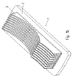
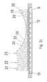
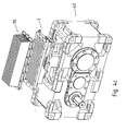
- FIG. 1a shows an inventive embodiment of a first cooling module.
- the first cooling module 1 consists of a module plate 2, on the underside of a molding is provided, which is formed as a plurality of parallel extending catch ribs 3.
- FIG. 1b is the first cooling module shown from below.
- the parallel locking ribs 3 have a tapering away from the module plate 2 thickness.
- the catch ribs 3 are designed congruent to each other and are made with the module cover 2 in one piece, in particular by sand casting or die casting, in aluminum.
- the catch ribs 3 are made of aluminum flat material separately and then connected by welding with the module plate 2 also made of aluminum.
- the catch ribs 3 and the module plate 2 are made of a metallic alloy, for example steel or copper or alloys of both.
- connection openings 10 are provided, which each open into a groove end 11 of the coolant groove 9.
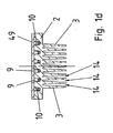
- Figure 1c shows a longitudinal section through the first cooling module 1.
- the sectional plane intersects the side surface of a gutter 3 approximately at mid-height.
- the Fangrippe 3 has three circular indentations 4, 5 and 6, which are separated by the circular intersection points 7 and 8.
- the radii of the circular indentations 4, 5 and 6 and the depth of their arching into the catching rib 3 are determined by the constructional and geometric conditions at the place of use of the first cooling module on a transmission, in particular by the radius and the position of the gears of the transmission.
- the three-part design shown advantageously has the effect that the cooling module can be used for different gear sets in the same gear housing.
- two or fewer or more than three circular bulges are provided, which are subdivided by circular intersections.
- slot-shaped interruptions running away from the module plate 2 are carried out on the catch ribs 3.
- Figure 1c also shows a portion of the coolant groove 9 with the groove bottom elevations 12.
- These groove bottom elevations 12 are designed as a rounded steps pillow-shaped, wherein the steps are arranged at equal intervals on the groove bottom.
- the groove bottom is wave-shaped, and / or the elevations are arranged at regular or irregular intervals, or the groove bottom is flat and thus designed without elevations.
- the groove bottom elevations have the effect that a liquid flowing in the coolant groove 9, for example a coolant, assumes a turbulent flow behavior, and thus has a good mixing, in particular with regard to the temperature distribution in the liquid.
- An aperture 17 connects the in Figure 1c shown portion of the coolant groove 9 with the adjacent portion of the coolant groove. 9
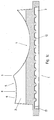
- Figure 1d shows a cross section through the first cooling module 1, on which a gear cover 49 is mounted.
- the coolant groove 9 forms a closed meandering channel through which coolant can flow, and which is connected to the outside only via the connection openings 10.
- the catch ribs 3 delimit collecting spaces 14, by means of which oil can be absorbed by the gear stages or the gear wheels when the cooling module is used according to the invention on a gear mechanism.
- the distance between the catch ribs is advantageously chosen so that the collecting spaces 14 formed by the catch ribs 3 each have a cross-section which is about as large as the Cross section of a catch rib 3.
- the inclination of the side surfaces of the catch ribs 3 relative to the module plate 2, the thickness of the catch ribs and the distance between the catch ribs are advantageously selected according to the specifications of the manufacturing process, such as sand casting or die casting.
- the distance between the ribs to each other is smaller or larger than the thickness of the catch ribs.
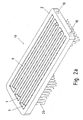
- FIG. 2a shows a further embodiment of a second cooling module according to the invention.
- the second cooling module 19 consists of a module plate 2, which on its underside have a shape in the form of catching fingers 20.
- the module plate 2 has a coolant groove 9 and connection openings 10 and is identical to the module plate of FIGS. 1a to 1d , thus, a cheap production of cooling modules in different variants, with catch ribs and / or catching fingers, allows.
- the second cooling module 19 is produced by the aluminum casting process.
- FIG. 2b shows the underside of the second cooling module 19.
- the catching fingers 20 are arranged in parallel longitudinal and transverse rows, so that continuous, parallel streets are formed in at least two directions.
- the catching fingers are arranged according to other regular or irregular patterns.
- the catching fingers 20 define catchment areas 21, by means of which, when the second cooling module is used according to the invention, oil can be taken up on a gear of its gear stages or its gear wheels in different directions, in particular obliquely or mutually perpendicular directions. This is advantageous over the embodiment according to FIG. 1a in which the catchment areas 14 mark a single direction.
- the catching fingers 20 have a round cross section with respect to their length, and they taper towards their end.
- the catching fingers in cross-section the shape of a polygon, in particular a three- or quadrilateral on.
- the shape of the cross-sectional area is oriented advantageously on the symmetry of the arrangement of the catching fingers on the module plate.
- the catch fingers can be manufactured together with the module plate with simple, inexpensive separation processes from a block.
- Figure 2c shows a longitudinal section through the in FIG. 2a shown second cooling module.
- the ends of the catching fingers 20 form an envelope in the longitudinal direction of the second cooling module 19, which describes three circular indentations. These circular indentations merge into conceptual circular intersections 22, 23.
- the radii of the circular indentations and the depth of their arching into the plane spanned by the catching fingers become due to the structural and geometric conditions at the place of use of the second cooling module on a transmission, in particular by the radius and the position of the rotating parts, such as gears, cyclo discs, eccentric discs or the like, of the transmission.
- two or fewer or more than three circular bulges are provided, which are subdivided by circular intersections.
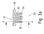
- FIG. 3a shows a cross section and FIG. 3b a longitudinal section along the section AA through a further inventive embodiment of a third cooling module.
- the third cooling module 29 consists of a module base 30 and a module top 31.
- the module base 30 comprises a plate and mutually parallel hollow ribs 32, in which corresponding solid ribs 33 of the module body 31 are arranged when the module top 31 on the module base 30 in the manner shown is attached.
- the longitudinal profile of the hollow ribs 32 after FIG. 3b describes an envelope, that of the catch ribs of the first cooling module 1 from Figure 1c like.
- the hollow ribs 32 and the solid ribs 33 form in the assembled position, as in FIG. 3b shown, in each case a coolant channel 34.
- These coolant channels 34 are connected via passages 35 so that a total of a meandering in two directions coolant channel is formed.
- the ends of the meandering coolant channel open out via two connection openings 36.
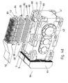
- FIG. 4a shows a use according to the invention of a first cooling module FIG. 1 a to 1 in a transmission 40, which comprises a housing 41 in monobloc construction, that is made of a single casting, with an opening 47.
- gears 45 are arranged on shafts. These gears 45 are accessible via the opening 47 for the purpose of assembly, inspection, maintenance or oil replacement.
- the opening is thus dimensioned such that the largest intended gear or Veriereteil is passed through them.
- the transmission in which the cooling module 1 is used, advantageously determines the structural dimensions of the cover 47 and thus of the cooling module 1.
- the length of the cover is approximately 30 cm in the exemplary embodiment described here. In other embodiments, this length is between 5 cm and 2 m.
- a shaft is mounted as a driving shaft 42 via a bearing in the housing 41, a cover 43 covers the end of the driven shaft of the transmission, which is led out of the housing 41 on the rear side, not shown.
- the opening 47 is closable with a housing cover 49, which is fastened by screws 52, which are screwed into threaded bores 57.
- the housing cover 49 is in a fixed position flat on the housing flange 51.
- sealing means between the housing flange 51 and housing cover 49 are provided which seal the interior of the housing 41 inwardly and outwardly, so that no oil can escape and no impurities can pass from the outside into the oil.
- the seal is effected by means of a metal adhesive, for example Loctite, which is applied to the flange surfaces.
- the seal is effected by an O-ring or paper seal circulating on the flange surface.
- Such a seal can be improved by a provided on the flange surfaces spring-groove system.
- a first cooling module 1 between housing flange 51 and housing cover 49 providable for this purpose, the underside of the module plate 2 of the cooling module 1 is placed on the housing flange 51.
- the module plate 2 has boreholes 58 which fit in arrangement and diameter to the threaded holes 57.
- the housing cover 49 can be fastened together with the first cooling module 1 via the screws 52 on the gear housing 41 by the screws 52 are inserted through the holes 58 and screwed into the threaded holes 57.
- a module flange surface 53 is provided, which forms a sealed closure of the interior of the transmission housing 41 with the housing cover 49.
- the necessary sealing means are not shown for the sake of simplicity.
- the underside of the module plate 2 with the housing flange 51 forms a tight seal of the interior.
- the coolant groove 9 is sealed in the module plate 2 to the outside so tightly that coolant, such as a cooling fluid such as water or oil, can flow in the channel thus formed without leaking.
- the necessary sealing means are not shown for the sake of simplicity. They are preferably provided on the surface of the module plate 2, but are also at least partially providable on the underside of the housing cover 49.
- On a side wall of the cooling module connecting devices in the form of two connection couplings 55 are provided. These connection couplings 55 run in the mounted position of the cooling module 1 tangentially to the outer surface of the transmission housing 41. Thus, the connection couplings 55 and connected thereto lines are protected by the cooling module 1 from damage. Coolant flows from a coolant circuit into the coolant groove 9 through a first connection coupling 55, and coolant flows from the coolant groove 9 back into the coolant circuit through a second connection coupling 55.
- the housing cover 49 is advantageously made of aluminum.
- the housing cover is made of steel or stainless steel and / or has at least on its side facing the coolant groove side corrosion-resistant and / or coolant-resistant coating, for example a paint or a plastic coating on.
- the plastic coating additionally causes the sealing of the connection of housing cover with cooling module.
- the catch ribs 3 of the first cooling module 1 protrude into the interior of the housing 41 through the imaginary boundary surface of the housing interior spanned by the opening 47, that is to say in particular by the housing flange surface 51.
- the longitudinal profile of the catch ribs 3 follows in the mounted position of the first cooling module 1 the shape of the gears 45, for which circular indentations are formed in the catch ribs 3.
- the number and shape of these circular indentations is chosen.
- the gears for the various gear ratios with which the housing 41 can be equipped are not inhibited in their intended movement by the catch ribs 3, on the other hand, the catch ribs 3 as closely as possible at least partially follow the swept by the gears area to the wheels to be able to absorb thrown off oil well.
- the distance between the catch ribs is chosen with particular regard to the viscosity of the oil so that the gears are not noticeably slowed down in their intended movement by located between catch ribs and gears oil.
- catch ribs 3 As advantageous, a three-part design of the catch ribs 3 in the illustrated manner Figure 1c Other embodiments of the catch ribs 3 are also included in the invention. For example, it is possible to project the catch ribs 3 laterally into the region of the housing interior to the left of the opening 47, as a result of which, in particular, the gearwheel on the driving shaft 42 is better covered.
- cooling fins are uneven and partially extend in areas adjacent gear 45th
- FIG. 4b shows the inventive use of another embodiment of a passive cooling module.
- a passive cooling module 60 is tightly mounted on the housing flange 51 of the transmission 40.
- the passive cooling module 60 has on its underside parallel extending Fangrippen 3, as in FIG. 4a protrude described in the interior of the transmission case 41. On its upper side, the passive cooling module 60 has parallel cooling fins 62.
- the cooling fins 62 are advantageously designed to be congruent to each other.
- the passive cooling module 60 is made in two parts, consisting of an upper part with cooling fins 62 and a lower part with catch ribs 3.
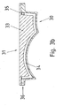
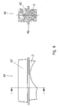
- Such an embodiment shows FIG. 6 , left side view and right side cross section.
- Upper and lower parts are connected to one another at a contact surface 110.
- the contact surface is additionally coated with a thermal paste.
- the passive cooling module 60 is produced in one piece, that is to say in particular from a single cast.
- the catching ribs 3 receive oil spun off the gearwheels 45, whereby heat is transported from the gearbox 40 to the catching ribs 3.
- the latter pass the heat via the body of the passive cooling module 60 to the cooling fins 62, which finally release the heat to the environment, for example air.
- FIG. 4c shows a further example of use of a cooling module according to the invention.
- a first module cover 70 having on its upper side parallel cooling fins 62.
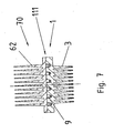
- Such a cooling module with module cover shows FIG. 7 in cross section.
- the contact surface 111 which connects the first module cover 70 with the first cooling module 1, has sealing means, not shown, in order to close off the coolant groove 9 to the outside.
- the intended use of the first cooling module 1 is carried out as in FIG. 4a described.
- the cooling capacity is additionally increased by the cooling ribs 62 provided on the module cover, via which heat can be emitted to the environment.
- the safety is increased, because even in case of failure of the coolant circuit emergency cooling can be done via the cooling fins 62.
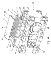
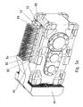
- FIG. 4d shows a further inventive use of a cooling module on a bevel gear.
- Oil module 80 is placed on this a coolant module 82 and on this a second module cover 84.
- Oil module 80, coolant module 82 and second module cover 84 each have corresponding holes 58 through which screws 52 are feasible to connect the modules (80, 82) and the lid 84 with the housing 41.
- the screws engage in threaded holes 57.
- Each Screw 52 advantageously causes the connection of all modules (80, 82) and the lid 84 with the housing 41 alike.
- the oil module 80 differs from the first cooling module 1 FIG. 1 a and 4a in that instead of the connection couplings 55 dummy plugs 86 are provided which close the connection openings 10, and that in addition to the underside of the module plate 2 holes are provided, which open via the closed connection openings 10 in the groove ends 11.
- the piping is formed from extending in the housing and outside of the housing tubes through which, for example, as a pressure circulation lubrication, in particular for gear or bearing lubrication, oil is pumped.
- the pump can be provided as a wave pump or as an electrically driven pump, which is preferably fastened to the outside of the transmission housing 41.
- the piping and / or the pump additionally have oil filters.
- the piping comprises a nozzle through which oil is passed or injected by the pressure circulation lubrication on the catch ribs 3.
- fittings 88 are formed as bores having additional sealing means.
- the coolant module 82 in FIG. 4d differs from the first cooling module 1 after FIG. 1a and 4a in that catch ribs 3 are not provided.
- a cooling medium circuit can be connected via connection couplings, via which heat can be removed from the oil module 80.
- the second module cover 84 in FIG. 4d has on its upper side on cooling fingers 89, which are arranged in longitudinal and transverse rows. Heat can be released from the coolant module 82 to the environment, in particular in air, via the cooling fingers 89.
- the bevel gear in FIG. 4d has on a front side, the Eintriebsseite 90 a driving shaft on which a fan 91 is mounted.
- the air moved by the fan 91 is partially directed by an air guiding device 92 onto the cooling fingers 89 of the second module cover 84, as a result of which a further increased cooling power can be achieved at the transmission.
- no fan is provided. Opposite the first module cover 70 of FIG. 6 In this case, cooling fingers 69 cause air to convectively flow in more than one direction. Thus, depending on the orientation of the transmission in the room - the design - improved heat dissipation achievable, even without a fan.
- FIG. 5a shows the device after FIG. 4d in assembled form.
- FIG. 5b shows a longitudinal section through a section of in FIG. 5a illustrated device.
- the longitudinal profile of the catch ribs 3 follows with its circular concavity 4 of the shape of the gear 45.
- the circular indentations 5, 6 are formed so that with a longitudinal profile enough space for different gears 46, but still thrown off oil is well received.
- a distance of the catch ribs of the gears of about 5mm has been found to be particularly advantageous for receiving the oil, but within the scope of manufacturing tolerances and smaller clearances conceivable
- Oil module 80, coolant module 82 and second module cover 84 form an oil passage 100 and a coolant passage 102.
- oil is pumped through the oil passage 100 via the pump of pressure circulation lubrication.
- Coolant is pumped through the coolant channel 102 via connection couplings 55 from a cooling circuit.
- a fan 91 guides air over the cooling fingers 89 via an air guiding device 92.
- the device after FIG. 4d . 5a and 5b thus forms a variety of ways in which heat from the transmission to the environment can be transported, From gears 45, 46 on thrown-off oil to catch ribs 3 and on to the oil module 80; from the oil sump via pipes 95 to the oil module 80; from the oil module 80 to the coolant module 82; from the coolant module 82 via the coolant in the coolant channel 102 to the coolant circuit; from the coolant module 82 via the second module cover 84 to the ambient air.
- a first module cover 70 is provided instead of the second module cover 84.
- the housing cover 49 is provided instead of the second module cover 84. In this case, at least the spoiler 92 can be omitted.
- FIGS. 4a to 4d show exemplary embodiments of cooling devices, which can be composed particularly advantageous from a kit.
- the opening 47 is designed as an interface for connecting to the various cooling modules or modules or covers.
- the housing cover which is mounted on the opening of a transmission without cooling device according to the invention, can be used to cover the coolant groove in a module additionally used for improving the cooling.
Landscapes
- Engineering & Computer Science (AREA)
- General Engineering & Computer Science (AREA)
- Mechanical Engineering (AREA)
- General Details Of Gearings (AREA)
Claims (8)
- Module de refroidissement destiné à une transmission,
la zone déformée, en saillie sur ledit module de refroidissement et tournée vers l'espace interne de la transmission, épousant le profil d'un élément rotatif ou de plusieurs éléments rotatifs de ladite transmission en vue d'améliorer la dissipation de chaleur, depuis ledit espace interne de la transmission, à l'aide d'une superficie agrandie dans la région spatiale de l'écoulement d'huile entre le carter et ledit ou lesdits élément(s),
ledit module de refroidissement comprenant une pièce venue de fonderie,
sachant qu'il est prévu, dans ladite pièce venue de fonderie, une région spatiale dédiée à un fluide de refroidissement en circulation, et délimitée par ladite pièce venue de fonderie et par une platine (49) de carter reliée, de manière étanche, à ladite pièce venue de fonderie, caractérisé par le fait
que des ailettes de refroidissement, pointant dans l'espace interne de la transmission et ménagées sur la pièce venue de fonderie, sont façonnées d'un seul tenant avec ladite pièce venue de fonderie ou sont rapportées par soudage sur ladite pièce venue de fonderie,
les extrémités desdites ailettes de refroidissement épousant le profil de l'élément rotatif de la transmission et étant disposées sur un arc de cercle, le rayon dudit arc de cercle étant déterminé par le rayon dudit élément rotatif,
sachant que la région spatiale, dévolue au fluide de refroidissement en circulation, se présente comme une rainure en forme de méandres. - Module de refroidissement selon la revendication 1,
caractérisé par le fait
que le fluide de refroidissement en circulation est de l'air, ou un liquide de refroidissement tel que de l'huile ou de l'eau. - Module de refroidissement selon au moins l'une des revendications précédentes,
caractérisé par le fait
qu'une première partie des extrémités des ailettes de refroidissement épouse le profil du premier élément rotatif de la transmission et est disposée sur un premier arc de cercle, le rayon dudit premier arc de cercle étant déterminé par le rayon dudit premier élément rotatif,
une autre partie des extrémités desdites ailettes de refroidissement épousant le profil d'un second élément rotatif de la transmission et étant disposée sur un second arc de cercle, le rayon dudit second arc de cercle étant déterminé par le rayon dudit second élément rotatif, sachant que lesdites première et seconde parties sont séparées l'une de l'autre par les points d'intersection des deux arcs de cercle. - Module de refroidissement selon au moins l'une des revendications précédentes,
caractérisé par le fait
que ledit module de refroidissement permet d'obturer un évidement ou orifice pratiqué dans le carter de la transmission, et dont la bordure périphérique délimite une surface minimale par laquelle la zone déformée en saillie pointe dans l'espace interne de ladite transmission. - Module de refroidissement selon au moins l'une des revendications précédentes,
caractérisé par le fait
que la zone déformée en saillie comprend des protubérances,
le bord extérieur des extrémités desdites protubérances épousant le profil de l'élément rotatif ou de plusieurs éléments rotatifs de la transmission. - Module de refroidissement selon au moins l'une des revendications précédentes,
caractérisé par le fait
que les protubérances sont de réalisation creuse, en vue de recevoir un fluide de refroidissement. - Module de refroidissement selon au moins l'une des revendications précédentes,
caractérisé par le fait
que la zone déformée en saillie pénètre dans des régions jouxtant les faces latérales de roues dentées de la transmission. - Module de refroidissement selon au moins l'une des revendications précédentes,
caractérisé par le fait
que la zone déformée en saillie s'étend le long d'un plan imaginaire, dont le tracé est transversal et perpendiculaire à l'axe de l'arbre de l'élément rotatif.
Priority Applications (2)
| Application Number | Priority Date | Filing Date | Title |
|---|---|---|---|
| EP10007209.9A EP2241787B1 (fr) | 2006-05-03 | 2007-04-24 | Radiateur pour boîte de vitesses, boîte de vitesses avec un dispositif de refroidissement, groupe de dispositifs de refroidissementde boîtes de vitesses et serie de boîte de vitesses |
| EP13004945.5A EP2687757B1 (fr) | 2006-05-03 | 2007-04-24 | Radiateur pour boite de vitesses, boite de vitesses avec un dispositif de refroidissement, groupe de dispositifs de refroidissementde boites de vitesses et serie de boite de vitesses |
Applications Claiming Priority (2)
| Application Number | Priority Date | Filing Date | Title |
|---|---|---|---|
| DE102006020801A DE102006020801A1 (de) | 2006-05-03 | 2006-05-03 | Kühler für Getriebe, Getriebe mit Kühlvorrichtung, Baukasten von Getriebekühlvorrichtungen und Baureihe von Getrieben |
| PCT/EP2007/003560 WO2007124885A2 (fr) | 2006-05-03 | 2007-04-24 | Radiateur pour boite de vitesses, boite de vitesses avec un dispositif de refroidissement, groupe de dispositifs de refroidissement de boites de vitesses et serie de boites de vitesses |
Related Child Applications (2)
| Application Number | Title | Priority Date | Filing Date |
|---|---|---|---|
| EP10007209.9A Division EP2241787B1 (fr) | 2006-05-03 | 2007-04-24 | Radiateur pour boîte de vitesses, boîte de vitesses avec un dispositif de refroidissement, groupe de dispositifs de refroidissementde boîtes de vitesses et serie de boîte de vitesses |
| EP13004945.5A Division EP2687757B1 (fr) | 2006-05-03 | 2007-04-24 | Radiateur pour boite de vitesses, boite de vitesses avec un dispositif de refroidissement, groupe de dispositifs de refroidissementde boites de vitesses et serie de boite de vitesses |
Publications (2)
| Publication Number | Publication Date |
|---|---|
| EP2016309A2 EP2016309A2 (fr) | 2009-01-21 |
| EP2016309B1 true EP2016309B1 (fr) | 2010-08-18 |
Family
ID=38198561
Family Applications (3)
| Application Number | Title | Priority Date | Filing Date |
|---|---|---|---|
| EP07724490A Active EP2016309B1 (fr) | 2006-05-03 | 2007-04-24 | Radiateur pour boite de vitesses, boite de vitesses avec un dispositif de refroidissement, groupe de dispositifs de refroidissement de boites de vitesses et serie de boites de vitesses |
| EP10007209.9A Active EP2241787B1 (fr) | 2006-05-03 | 2007-04-24 | Radiateur pour boîte de vitesses, boîte de vitesses avec un dispositif de refroidissement, groupe de dispositifs de refroidissementde boîtes de vitesses et serie de boîte de vitesses |
| EP13004945.5A Active EP2687757B1 (fr) | 2006-05-03 | 2007-04-24 | Radiateur pour boite de vitesses, boite de vitesses avec un dispositif de refroidissement, groupe de dispositifs de refroidissementde boites de vitesses et serie de boite de vitesses |
Family Applications After (2)
| Application Number | Title | Priority Date | Filing Date |
|---|---|---|---|
| EP10007209.9A Active EP2241787B1 (fr) | 2006-05-03 | 2007-04-24 | Radiateur pour boîte de vitesses, boîte de vitesses avec un dispositif de refroidissement, groupe de dispositifs de refroidissementde boîtes de vitesses et serie de boîte de vitesses |
| EP13004945.5A Active EP2687757B1 (fr) | 2006-05-03 | 2007-04-24 | Radiateur pour boite de vitesses, boite de vitesses avec un dispositif de refroidissement, groupe de dispositifs de refroidissementde boites de vitesses et serie de boite de vitesses |
Country Status (5)
| Country | Link |
|---|---|
| EP (3) | EP2016309B1 (fr) |
| CN (2) | CN102305286B (fr) |
| AT (1) | ATE478286T1 (fr) |
| DE (3) | DE102006062729B4 (fr) |
| WO (1) | WO2007124885A2 (fr) |
Families Citing this family (32)
| Publication number | Priority date | Publication date | Assignee | Title |
|---|---|---|---|---|
| DE102008017643B4 (de) | 2008-04-04 | 2016-09-15 | Sew-Eurodrive Gmbh & Co Kg | Adapter, Getriebe und Antrieb |
| DE102008017755A1 (de) * | 2008-04-07 | 2009-10-15 | Sew-Eurodrive Gmbh & Co. Kg | Kühlanordnung für ein Getriebe, Getriebe und Antrieb |
| DE102009014317A1 (de) * | 2009-03-25 | 2010-10-07 | Sew-Eurodrive Gmbh & Co. Kg | Getriebe |
| DE102009014316B4 (de) | 2009-03-25 | 2019-03-14 | Sew-Eurodrive Gmbh & Co Kg | Getriebe |
| DE102009014315B4 (de) | 2009-03-25 | 2018-01-25 | Sew-Eurodrive Gmbh & Co Kg | Getriebe |
| DE102009061042A1 (de) | 2009-03-25 | 2011-01-05 | Sew-Eurodrive Gmbh & Co. Kg | Zumindest teilweise mit Öl befülltes Getriebe |
| DE102009015380A1 (de) | 2009-03-27 | 2010-09-30 | Sms Siemag Aktiengesellschaft | Stranggussgetriebe mit Hitzeabschirmung |
| DE102009025027B3 (de) | 2009-06-10 | 2011-02-10 | Siemens Aktiengesellschaft | Industriegetriebe |
| DE102009037548A1 (de) | 2009-08-17 | 2011-04-07 | Sew-Eurodrive Gmbh & Co. Kg | Gehäuseteil für ein Getriebe und Verfahren zur Herstellung |
| DE102010010816A1 (de) | 2010-03-09 | 2011-09-15 | Sew-Eurodrive Gmbh & Co. Kg | Getriebe |
| EP2410210B1 (fr) | 2010-07-22 | 2013-03-27 | Siemens Aktiengesellschaft | Engrenage pour applications industrielles |
| PL2410209T3 (pl) | 2010-07-22 | 2013-08-30 | Siemens Ag | Urządzenie chłodzące dla przekładni |
| CN102330809A (zh) * | 2011-07-12 | 2012-01-25 | 许晓华 | 一种减速箱 |
| CN102330811A (zh) * | 2011-07-29 | 2012-01-25 | 浙江伟博包装印刷品有限公司 | 一种变速箱 |
| CN102328488A (zh) * | 2011-07-29 | 2012-01-25 | 浙江伟博包装印刷品有限公司 | 一种变速器 |
| DE102012012840A1 (de) * | 2012-06-19 | 2013-12-19 | Getrag Getriebe- Und Zahnradfabrik Hermann Hagenmeyer Gmbh & Cie Kg | Gehäuseanordnung für eine Kupplungs-/Getriebeanordnung |
| DE102013009527A1 (de) * | 2013-06-07 | 2014-12-11 | Sew-Eurodrive Gmbh & Co Kg | Verwendung einer Befestigungsschraube eines Getriebes zur Adaptierung eines Sensors und Getreibe mit einem mittels einer Schraube an einem Getriebegehäuseteil schraubverbundenem Deckelteil |
| CN103825404B (zh) * | 2014-03-25 | 2016-07-06 | 北汽大洋电机科技有限公司 | 电机与变速器集成冷却系统 |
| DE102014113496A1 (de) * | 2014-09-18 | 2016-03-24 | Getrag Getriebe- Und Zahnradfabrik Hermann Hagenmeyer Gmbh & Cie Kg | Gehäuseanordnung |
| US9777824B2 (en) * | 2014-11-07 | 2017-10-03 | Modine Manufacturing Company | Cooled gear housing assembly |
| DE102017206598A1 (de) * | 2017-04-19 | 2018-10-25 | Zf Friedrichshafen Ag | Getriebegehäuse mit integrierten Ölkanälen |
| CN107185818A (zh) * | 2017-07-13 | 2017-09-22 | 唐山冀东装备工程股份有限公司 | 履带移动式水平筛分站 |
| FR3071029A1 (fr) * | 2017-09-13 | 2019-03-15 | Redex | Bati pour organe moteur ou dispositif de transmission, organe moteur et/ou dispositif de transmission associe |
| DE102017221321A1 (de) * | 2017-11-28 | 2019-05-29 | Mahle International Gmbh | Ölkühler für ein Getriebe und ein Getriebe |
| US10458534B1 (en) * | 2018-05-31 | 2019-10-29 | Abb Schweiz Ag | Gearbox system with add-on cooling fin panels |
| EP3627002B1 (fr) * | 2018-09-20 | 2021-06-30 | Flender GmbH | Boîte de vitesse et procédé de fabrication d'une telle boîte de vitesse |
| FR3109799B1 (fr) * | 2020-04-30 | 2022-07-29 | Renault | Procede et dispositif de controle thermique de boite de vitesses |
| DE102021002053A1 (de) | 2020-05-20 | 2021-11-25 | Sew-Eurodrive Gmbh & Co Kg | Kühlplatte und Getriebe mit einer Kühlplatte |
| US11261956B2 (en) * | 2020-07-02 | 2022-03-01 | Rivian Ip Holdings, Llc | Gearbox having internal cooling pins |
| CN112377597A (zh) * | 2020-10-30 | 2021-02-19 | 张荣兵 | 一种蜗轮蜗杆减速器 |
| CN113864435B (zh) * | 2021-10-25 | 2023-03-03 | 智新科技股份有限公司 | 减速器润滑油冷却系统及方法 |
| WO2024050792A1 (fr) * | 2022-09-08 | 2024-03-14 | 广东逸动科技有限公司 | Dispositif d'alimentation, propulseur et appareil mobile sur un plan d'eau |
Family Cites Families (15)
| Publication number | Priority date | Publication date | Assignee | Title |
|---|---|---|---|---|
| US2325647A (en) | 1942-09-15 | 1943-08-03 | Twin Disc Clutch Co | Air-cooled transmission |
| DE8212219U1 (de) * | 1982-04-28 | 1982-09-16 | Kupka, Dieter, 6570 Kirn | Stufenlos regelbares grundgetriebe fuer getriebebausaetze |
| SE455716B (sv) * | 1987-02-24 | 1988-08-01 | Hypeco Ab | Vermevexlingsanordning for kylning av en maskin |
| WO1991004427A1 (fr) | 1989-09-23 | 1991-04-04 | Zahnradfabrik Friedrichshafen Ag | Carter de boite de vitesses |
| AT404298B (de) | 1997-01-10 | 1998-10-27 | Ktm Kuehler Gmbh | Kühler für das öl im gehäuse eines getriebes |
| DE19704226B4 (de) | 1997-02-05 | 2004-09-30 | Sew-Eurodrive Gmbh & Co. Kg | Klemmdeckelumrichter |
| US6155135A (en) * | 1998-11-23 | 2000-12-05 | American Axle & Manufacturing, Inc. | Drive unit with lubricant cooling cover |
| US6202736B1 (en) * | 1999-08-19 | 2001-03-20 | Verlyn R. Fast | Vehicle transmission fluid cooler |
| JP3757765B2 (ja) * | 2000-06-23 | 2006-03-22 | いすゞ自動車株式会社 | 変速機のケース構造 |
| US6997238B1 (en) * | 2001-02-27 | 2006-02-14 | W.S. Darley & Co. | Cooler plate and gearbox assembly |
| GB2387206B (en) * | 2002-04-04 | 2005-08-10 | Ford Global Tech Inc | A transmission housing with cooling passageways |
| DE10245791A1 (de) * | 2002-10-01 | 2004-04-15 | Daimlerchrysler Ag | Getriebegehäuse |
| DE102004022863B4 (de) * | 2004-05-06 | 2010-08-05 | Sew-Eurodrive Gmbh & Co. Kg | Getriebe |
| DE102005026657B4 (de) * | 2004-08-17 | 2012-04-12 | Sew-Eurodrive Gmbh & Co. Kg | Gehäuse, Getriebe und Getriebebaukasten |
| DE202005005452U1 (de) * | 2005-04-06 | 2006-08-17 | Getriebebau Nord Gmbh & Co. Kg | Kühler für ein Getriebe |
-
2006
- 2006-05-03 DE DE102006062729.6A patent/DE102006062729B4/de active Active
- 2006-05-03 DE DE102006020801A patent/DE102006020801A1/de active Pending
-
2007
- 2007-04-24 CN CN201110217748.3A patent/CN102305286B/zh active Active
- 2007-04-24 CN CN200780015647XA patent/CN101432552B/zh active Active
- 2007-04-24 EP EP07724490A patent/EP2016309B1/fr active Active
- 2007-04-24 WO PCT/EP2007/003560 patent/WO2007124885A2/fr active Application Filing
- 2007-04-24 DE DE502007004791T patent/DE502007004791D1/de active Active
- 2007-04-24 AT AT07724490T patent/ATE478286T1/de active
- 2007-04-24 EP EP10007209.9A patent/EP2241787B1/fr active Active
- 2007-04-24 EP EP13004945.5A patent/EP2687757B1/fr active Active
Also Published As
| Publication number | Publication date |
|---|---|
| ATE478286T1 (de) | 2010-09-15 |
| EP2241787A2 (fr) | 2010-10-20 |
| WO2007124885A2 (fr) | 2007-11-08 |
| CN102305286A (zh) | 2012-01-04 |
| EP2241787B1 (fr) | 2014-07-02 |
| CN101432552A (zh) | 2009-05-13 |
| DE102006020801A1 (de) | 2007-11-15 |
| CN101432552B (zh) | 2012-03-28 |
| EP2687757A1 (fr) | 2014-01-22 |
| EP2241787A3 (fr) | 2011-03-16 |
| DE502007004791D1 (de) | 2010-09-30 |
| WO2007124885A3 (fr) | 2008-02-07 |
| DE102006062729A1 (de) | 2007-11-15 |
| DE102006062729B4 (de) | 2020-06-10 |
| EP2687757B1 (fr) | 2015-09-16 |
| EP2016309A2 (fr) | 2009-01-21 |
| CN102305286B (zh) | 2014-11-05 |
Similar Documents
| Publication | Publication Date | Title |
|---|---|---|
| EP2016309B1 (fr) | Radiateur pour boite de vitesses, boite de vitesses avec un dispositif de refroidissement, groupe de dispositifs de refroidissement de boites de vitesses et serie de boites de vitesses | |
| EP2162645B1 (fr) | Reducteur comprenant un module echangeur thermique et serie de reducteur | |
| DE19519740B4 (de) | Wärmetauscher | |
| DE19812677B4 (de) | Verteilergetriebe für ein vierradgetriebenes Kraftfahrzeug | |
| DE112008003585T5 (de) | Achsanordnung mit Achsgehäuseanordnung mit Lufteinlässen zum Kühlen | |
| DE102007020453A1 (de) | Getriebe, Schmiermittel-Kreislaufsystem und Getriebebaureihe | |
| EP0466746B1 (fr) | Essieu moteur | |
| DE60023992T2 (de) | Plattenwärmetauscher, insbesondere Ölkühler für Kraftfahrzeuge | |
| DE3739084A1 (de) | Platte fuer den durchfluss eines kuehlmittels sowie mit derartiger kuehlplatte ausgestattete gegenstaende | |
| EP0961095B1 (fr) | Refroidisseur | |
| DE102015221234A1 (de) | Stirnradgetriebe | |
| DE4011022A1 (de) | Triebachse | |
| DE602006000990T2 (de) | Schmiervorrichtung mindestens eines Zahnrades eines Getriebes | |
| DE19533140C1 (de) | Gehäuse für ein Getriebe eines Kraftfahrzeuges mit einer Entlüftungskammer | |
| DE112018006046T5 (de) | Dualfunktionelles achsenwärmemanagementsystem | |
| EP3614022B1 (fr) | Transmission hybride | |
| WO2006005328A1 (fr) | Module huile avec pompe a eau et echangeur de chaleur | |
| DE2013940A1 (de) | Wärmeübertrager für flüssige und gasförmige Medien | |
| DE10132120A1 (de) | Ölkühler | |
| DE3902786C2 (de) | Ölkühler | |
| EP3926215A1 (fr) | Dispositif d'amélioration du refroidissement d'une boîte de vitesses | |
| EP3670965B1 (fr) | Dispositif de transmission pour un multicopter | |
| EP1989500B1 (fr) | BOÎTIER AVEC ÉLÉMENT DE MACHINE ROTATIf ET ÉCHANGEUR DE CHALEUR ET PROCÉDÉ DE PRODUCTION | |
| WO2017182308A1 (fr) | Système de refroidissement pour robot | |
| DE19847206A1 (de) | Wellenlagerung |
Legal Events
| Date | Code | Title | Description |
|---|---|---|---|
| PUAI | Public reference made under article 153(3) epc to a published international application that has entered the european phase |
Free format text: ORIGINAL CODE: 0009012 |
|
| 17P | Request for examination filed |
Effective date: 20081203 |
|
| AK | Designated contracting states |
Kind code of ref document: A2 Designated state(s): AT BE BG CH CY CZ DE DK EE ES FI FR GB GR HU IE IS IT LI LT LU LV MC MT NL PL PT RO SE SI SK TR |
|
| AX | Request for extension of the european patent |
Extension state: AL BA HR MK RS |
|
| 17Q | First examination report despatched |
Effective date: 20090204 |
|
| RIN1 | Information on inventor provided before grant (corrected) |
Inventor name: LEONHARD, STEFFEN Inventor name: SAAR, STEFFEN Inventor name: MULLER, MANFRED |
|
| DAX | Request for extension of the european patent (deleted) | ||
| GRAP | Despatch of communication of intention to grant a patent |
Free format text: ORIGINAL CODE: EPIDOSNIGR1 |
|
| GRAS | Grant fee paid |
Free format text: ORIGINAL CODE: EPIDOSNIGR3 |
|
| GRAA | (expected) grant |
Free format text: ORIGINAL CODE: 0009210 |
|
| AK | Designated contracting states |
Kind code of ref document: B1 Designated state(s): AT BE BG CH CY CZ DE DK EE ES FI FR GB GR HU IE IS IT LI LT LU LV MC MT NL PL PT RO SE SI SK TR |
|
| REG | Reference to a national code |
Ref country code: GB Ref legal event code: FG4D Free format text: NOT ENGLISH |
|
| REG | Reference to a national code |
Ref country code: CH Ref legal event code: EP |
|
| REG | Reference to a national code |
Ref country code: IE Ref legal event code: FG4D Free format text: LANGUAGE OF EP DOCUMENT: GERMAN |
|
| REF | Corresponds to: |
Ref document number: 502007004791 Country of ref document: DE Date of ref document: 20100930 Kind code of ref document: P |
|
| REG | Reference to a national code |
Ref country code: NL Ref legal event code: VDEP Effective date: 20100818 |
|
| LTIE | Lt: invalidation of european patent or patent extension |
Effective date: 20100818 |
|
| PG25 | Lapsed in a contracting state [announced via postgrant information from national office to epo] |
Ref country code: LT Free format text: LAPSE BECAUSE OF FAILURE TO SUBMIT A TRANSLATION OF THE DESCRIPTION OR TO PAY THE FEE WITHIN THE PRESCRIBED TIME-LIMIT Effective date: 20100818 Ref country code: FI Free format text: LAPSE BECAUSE OF FAILURE TO SUBMIT A TRANSLATION OF THE DESCRIPTION OR TO PAY THE FEE WITHIN THE PRESCRIBED TIME-LIMIT Effective date: 20100818 |
|
| PG25 | Lapsed in a contracting state [announced via postgrant information from national office to epo] |
Ref country code: PL Free format text: LAPSE BECAUSE OF FAILURE TO SUBMIT A TRANSLATION OF THE DESCRIPTION OR TO PAY THE FEE WITHIN THE PRESCRIBED TIME-LIMIT Effective date: 20100818 Ref country code: IS Free format text: LAPSE BECAUSE OF FAILURE TO SUBMIT A TRANSLATION OF THE DESCRIPTION OR TO PAY THE FEE WITHIN THE PRESCRIBED TIME-LIMIT Effective date: 20101218 Ref country code: SI Free format text: LAPSE BECAUSE OF FAILURE TO SUBMIT A TRANSLATION OF THE DESCRIPTION OR TO PAY THE FEE WITHIN THE PRESCRIBED TIME-LIMIT Effective date: 20100818 Ref country code: PT Free format text: LAPSE BECAUSE OF FAILURE TO SUBMIT A TRANSLATION OF THE DESCRIPTION OR TO PAY THE FEE WITHIN THE PRESCRIBED TIME-LIMIT Effective date: 20101220 Ref country code: CY Free format text: LAPSE BECAUSE OF FAILURE TO SUBMIT A TRANSLATION OF THE DESCRIPTION OR TO PAY THE FEE WITHIN THE PRESCRIBED TIME-LIMIT Effective date: 20100818 Ref country code: BG Free format text: LAPSE BECAUSE OF FAILURE TO SUBMIT A TRANSLATION OF THE DESCRIPTION OR TO PAY THE FEE WITHIN THE PRESCRIBED TIME-LIMIT Effective date: 20101118 |
|
| REG | Reference to a national code |
Ref country code: IE Ref legal event code: FD4D |
|
| PG25 | Lapsed in a contracting state [announced via postgrant information from national office to epo] |
Ref country code: LV Free format text: LAPSE BECAUSE OF FAILURE TO SUBMIT A TRANSLATION OF THE DESCRIPTION OR TO PAY THE FEE WITHIN THE PRESCRIBED TIME-LIMIT Effective date: 20100818 Ref country code: NL Free format text: LAPSE BECAUSE OF FAILURE TO SUBMIT A TRANSLATION OF THE DESCRIPTION OR TO PAY THE FEE WITHIN THE PRESCRIBED TIME-LIMIT Effective date: 20100818 Ref country code: GR Free format text: LAPSE BECAUSE OF FAILURE TO SUBMIT A TRANSLATION OF THE DESCRIPTION OR TO PAY THE FEE WITHIN THE PRESCRIBED TIME-LIMIT Effective date: 20101119 Ref country code: SE Free format text: LAPSE BECAUSE OF FAILURE TO SUBMIT A TRANSLATION OF THE DESCRIPTION OR TO PAY THE FEE WITHIN THE PRESCRIBED TIME-LIMIT Effective date: 20100818 |
|
| PG25 | Lapsed in a contracting state [announced via postgrant information from national office to epo] |
Ref country code: IE Free format text: LAPSE BECAUSE OF FAILURE TO SUBMIT A TRANSLATION OF THE DESCRIPTION OR TO PAY THE FEE WITHIN THE PRESCRIBED TIME-LIMIT Effective date: 20100818 Ref country code: DK Free format text: LAPSE BECAUSE OF FAILURE TO SUBMIT A TRANSLATION OF THE DESCRIPTION OR TO PAY THE FEE WITHIN THE PRESCRIBED TIME-LIMIT Effective date: 20100818 |
|
| PG25 | Lapsed in a contracting state [announced via postgrant information from national office to epo] |
Ref country code: IT Free format text: LAPSE BECAUSE OF FAILURE TO SUBMIT A TRANSLATION OF THE DESCRIPTION OR TO PAY THE FEE WITHIN THE PRESCRIBED TIME-LIMIT Effective date: 20100818 Ref country code: RO Free format text: LAPSE BECAUSE OF FAILURE TO SUBMIT A TRANSLATION OF THE DESCRIPTION OR TO PAY THE FEE WITHIN THE PRESCRIBED TIME-LIMIT Effective date: 20100818 Ref country code: CZ Free format text: LAPSE BECAUSE OF FAILURE TO SUBMIT A TRANSLATION OF THE DESCRIPTION OR TO PAY THE FEE WITHIN THE PRESCRIBED TIME-LIMIT Effective date: 20100818 Ref country code: EE Free format text: LAPSE BECAUSE OF FAILURE TO SUBMIT A TRANSLATION OF THE DESCRIPTION OR TO PAY THE FEE WITHIN THE PRESCRIBED TIME-LIMIT Effective date: 20100818 Ref country code: SK Free format text: LAPSE BECAUSE OF FAILURE TO SUBMIT A TRANSLATION OF THE DESCRIPTION OR TO PAY THE FEE WITHIN THE PRESCRIBED TIME-LIMIT Effective date: 20100818 |
|
| PLBE | No opposition filed within time limit |
Free format text: ORIGINAL CODE: 0009261 |
|
| STAA | Information on the status of an ep patent application or granted ep patent |
Free format text: STATUS: NO OPPOSITION FILED WITHIN TIME LIMIT |
|
| PG25 | Lapsed in a contracting state [announced via postgrant information from national office to epo] |
Ref country code: ES Free format text: LAPSE BECAUSE OF FAILURE TO SUBMIT A TRANSLATION OF THE DESCRIPTION OR TO PAY THE FEE WITHIN THE PRESCRIBED TIME-LIMIT Effective date: 20101129 |
|
| 26N | No opposition filed |
Effective date: 20110519 |
|
| REG | Reference to a national code |
Ref country code: DE Ref legal event code: R097 Ref document number: 502007004791 Country of ref document: DE Effective date: 20110519 |
|
| BERE | Be: lapsed |
Owner name: SEW-EURODRIVE G.M.B.H. & CO. KG Effective date: 20110430 |
|
| PG25 | Lapsed in a contracting state [announced via postgrant information from national office to epo] |
Ref country code: MC Free format text: LAPSE BECAUSE OF NON-PAYMENT OF DUE FEES Effective date: 20110430 |
|
| REG | Reference to a national code |
Ref country code: CH Ref legal event code: PL |
|
| PG25 | Lapsed in a contracting state [announced via postgrant information from national office to epo] |
Ref country code: MT Free format text: LAPSE BECAUSE OF FAILURE TO SUBMIT A TRANSLATION OF THE DESCRIPTION OR TO PAY THE FEE WITHIN THE PRESCRIBED TIME-LIMIT Effective date: 20100818 |
|
| PG25 | Lapsed in a contracting state [announced via postgrant information from national office to epo] |
Ref country code: LI Free format text: LAPSE BECAUSE OF NON-PAYMENT OF DUE FEES Effective date: 20110430 Ref country code: BE Free format text: LAPSE BECAUSE OF NON-PAYMENT OF DUE FEES Effective date: 20110430 Ref country code: CH Free format text: LAPSE BECAUSE OF NON-PAYMENT OF DUE FEES Effective date: 20110430 |
|
| PG25 | Lapsed in a contracting state [announced via postgrant information from national office to epo] |
Ref country code: LU Free format text: LAPSE BECAUSE OF NON-PAYMENT OF DUE FEES Effective date: 20110424 |
|
| REG | Reference to a national code |
Ref country code: AT Ref legal event code: MM01 Ref document number: 478286 Country of ref document: AT Kind code of ref document: T Effective date: 20120424 |
|
| PG25 | Lapsed in a contracting state [announced via postgrant information from national office to epo] |
Ref country code: AT Free format text: LAPSE BECAUSE OF NON-PAYMENT OF DUE FEES Effective date: 20120424 |
|
| PG25 | Lapsed in a contracting state [announced via postgrant information from national office to epo] |
Ref country code: TR Free format text: LAPSE BECAUSE OF FAILURE TO SUBMIT A TRANSLATION OF THE DESCRIPTION OR TO PAY THE FEE WITHIN THE PRESCRIBED TIME-LIMIT Effective date: 20100818 |
|
| PG25 | Lapsed in a contracting state [announced via postgrant information from national office to epo] |
Ref country code: HU Free format text: LAPSE BECAUSE OF FAILURE TO SUBMIT A TRANSLATION OF THE DESCRIPTION OR TO PAY THE FEE WITHIN THE PRESCRIBED TIME-LIMIT Effective date: 20100818 |
|
| REG | Reference to a national code |
Ref country code: FR Ref legal event code: PLFP Year of fee payment: 10 |
|
| REG | Reference to a national code |
Ref country code: FR Ref legal event code: PLFP Year of fee payment: 11 |
|
| REG | Reference to a national code |
Ref country code: FR Ref legal event code: PLFP Year of fee payment: 12 |
|
| PGFP | Annual fee paid to national office [announced via postgrant information from national office to epo] |
Ref country code: FR Payment date: 20230309 Year of fee payment: 17 |
|
| PGFP | Annual fee paid to national office [announced via postgrant information from national office to epo] |
Ref country code: DE Payment date: 20230430 Year of fee payment: 17 |
|
| PGFP | Annual fee paid to national office [announced via postgrant information from national office to epo] |
Ref country code: GB Payment date: 20240229 Year of fee payment: 18 |