EP2016309B1 - Cooler for transmission, transmission with cooling device, modular system of transmission cooling devices, and type series of transmissions - Google Patents
Cooler for transmission, transmission with cooling device, modular system of transmission cooling devices, and type series of transmissions Download PDFInfo
- Publication number
- EP2016309B1 EP2016309B1 EP07724490A EP07724490A EP2016309B1 EP 2016309 B1 EP2016309 B1 EP 2016309B1 EP 07724490 A EP07724490 A EP 07724490A EP 07724490 A EP07724490 A EP 07724490A EP 2016309 B1 EP2016309 B1 EP 2016309B1
- Authority
- EP
- European Patent Office
- Prior art keywords
- cooling
- cooling module
- transmission
- module
- housing
- Prior art date
- Legal status (The legal status is an assumption and is not a legal conclusion. Google has not performed a legal analysis and makes no representation as to the accuracy of the status listed.)
- Active
Links
Images


Classifications
-
- F—MECHANICAL ENGINEERING; LIGHTING; HEATING; WEAPONS; BLASTING
- F16—ENGINEERING ELEMENTS AND UNITS; GENERAL MEASURES FOR PRODUCING AND MAINTAINING EFFECTIVE FUNCTIONING OF MACHINES OR INSTALLATIONS; THERMAL INSULATION IN GENERAL
- F16H—GEARING
- F16H57/00—General details of gearing
- F16H57/04—Features relating to lubrication or cooling or heating
- F16H57/0412—Cooling or heating; Control of temperature
- F16H57/0415—Air cooling or ventilation; Heat exchangers; Thermal insulations
- F16H57/0417—Heat exchangers adapted or integrated in the gearing
-
- F—MECHANICAL ENGINEERING; LIGHTING; HEATING; WEAPONS; BLASTING
- F16—ENGINEERING ELEMENTS AND UNITS; GENERAL MEASURES FOR PRODUCING AND MAINTAINING EFFECTIVE FUNCTIONING OF MACHINES OR INSTALLATIONS; THERMAL INSULATION IN GENERAL
- F16H—GEARING
- F16H57/00—General details of gearing
- F16H57/02—Gearboxes; Mounting gearing therein
- F16H2057/02039—Gearboxes for particular applications
- F16H2057/02069—Gearboxes for particular applications for industrial applications
- F16H2057/02073—Reduction gearboxes for industry
-
- F—MECHANICAL ENGINEERING; LIGHTING; HEATING; WEAPONS; BLASTING
- F16—ENGINEERING ELEMENTS AND UNITS; GENERAL MEASURES FOR PRODUCING AND MAINTAINING EFFECTIVE FUNCTIONING OF MACHINES OR INSTALLATIONS; THERMAL INSULATION IN GENERAL
- F16H—GEARING
- F16H57/00—General details of gearing
- F16H57/02—Gearboxes; Mounting gearing therein
- F16H57/033—Series gearboxes, e.g. gearboxes based on the same design being available in different sizes or gearboxes using a combination of several standardised units
Definitions
- the invention relates to a radiator for transmission, a transmission with cooling device, a kit of transmission cooling devices and a series of gearboxes.
- a cooler for the oil in the housing of a transmission in which the housing is a heat exchanger used as a cover in an opening of the transmission housing, wherein the interior of the transmission housing facing wall of the heat exchanger housing forms the heat exchanger plate.
- a transmission and a kit of transmissions is known, in which.
- a cover of the transmission housing has outwardly projecting cold fingers, which are referred to there as a cooling device.
- a transmission is known in which a closure member has inwardly and outwardly directed cooling fins.
- a passive radiator which is designed as a housing part of a transmission.
- the invention has the object of developing a transmission so that the transmission cooling is improved.
- the object is achieved in the cooling module for a transmission according to the features specified in claim 1.
- the advantage here is that an improvement in the heat dissipation from the inside of the gearbox by means of an enlarged surface in the space region of the oil flow between the part or parts and the housing is providable.
- the interior of the transmission of adevorricht is better exploitable. Because the flow of oil within the transmission can be scholarleitbar on that surface of the cooling module, which by means of the ins Geared inside projecting shape is increased. As a result, a smaller distance between the heat source and the cooling module surface can be achieved, and the heat transfer is improved.
- the oil flow is better utilized. Because the essential part of the oil flow is now so conductive that it comes into contact with the surface for heat dissipation.
- the shape is advantageously so close to the gear teeth approachable that only negligible parts of the oil flow lost for the heat dissipation to the cooling module.
- a lubricant having higher viscosity than oil such as grease or grease, is usable. Such a lubricant at least partially adheres to the gear portion, as long as the temperature of the transmission is low. By means of the invention, the closely approached formations can still come into contact with this lubricant portion.
- the cooling module comprises a casting, wherein in the casting a space area for flowing coolant, in particular oil or air or water, is provided, and wherein the casting gear inside the cooling fin and / or cooling fingers are mounted, in particular integrally with the casting molded or welded to the casting.
- the cooling module thus has a variable thickness in the longitudinal direction of the casting.
- the advantage here is that two separate space areas are providable, a first for a flowing coolant, such as air, water or oil, and a second, located inside the gear, for the contact of cooling fins or cooling fingers with flowing in the gearbox oil, so lubricating oil.
- a thick metal part is providable as a casting, whereby the cooling module is robust against mechanical stresses.
- Another advantage is that the separation of the two spatial areas redundant security can be achieved against mixing of coolant and lubricating oil. Because even if a seal of the space area for the coolant should be leaking, the coolant would not be able to enter the gearbox interior but would flow outside of the geared interior enclosed by the casting.
- the formation of the cooling module facing the inside of the gear unit follows the shape of a rotating part or several rotating parts of the gear unit in such a way that heat from the space area, in particular substantially from the entire space area, of the oil flow between the part or parts and the housing can be transported away.
- it is advantageous for improving the heat dissipation from the oil to the transmission environment in space regions of the oil flow heat absorbable by the shaping.
- a tracking of the shape of a rotating part of the transmission is achieved if around the rotating part a concentric circle or a concentric ellipse with small eccentricity can be drawn, which or has common points with the mathematically idealized surface of the molding, the or but the mathematical interior of the formation does not intersect.
- the shape of the molding and thus also the consequences of the shape of the rotating part, is advantageously provided such that the lubricant flow or oil flow generated by the rotating part for heat dissipation as completely as possible is brought into contact with the surface of the molding.
- the flow resistance for the stream should be kept small.
- the shape of the shape is selected so that on the one hand, the gears or toothed parts, such as cyclo discs or eccentric, the transmission for the various gear ratios with which the gear is equipped, are not inhibited in their intended movement by the formation, on the other hand, the formation as closely as possible at least partially followed by the rotating parts, in particular the gears, swept area to be able to absorb from the rotating parts, in particular the gears, flung oil well.
- the advantage here is that the distance of the molding to a rotating part or more rotating parts is as small as possible. The minimum distance of the molding to the rotating parts is mainly determined by the manufacturing tolerances of the gear housing and the cooling module.
- the interface for tightly sealing connection of the cooling module with the gearbox comprises a seal, wherein in particular the formation protrudes through the surface bounded by the seal into the interior of the transmission.
- the bordered by the seal minimal surface serves to separate the inside and outside of the gear housing with respect to the interface belonging opening.
- the minimum area is obtained by reducing the seal to an idealized closed line which circumscribes and thus describes the opening, and by inserting into the line a portion of a bubble whose edge is formed by the closed line and which otherwise leave itself becomes.
- the cooling module is thus generally a recess, in particular opening, closable in the gear housing, the border defines a minimum surface through which the molding projects into the interior of the transmission through.
- the formation comprises ribs, which in particular have slot-shaped interruptions, wherein the outer edge of the ribs follows the shape of a rotating part or a plurality of rotating parts of the transmission.
- the ribs advantageously form surfaces which, on the one hand, carry the oil flow and, on the other hand, absorb heat from the oil flow.
- the distance of the ribs from each other is advantageously selected in accordance with the viscosity of the lubricating oil minimally such that a flow of the oil takes place in the spaces between the ribs with low flow resistance.
- the distance of the ribs and the thickness of the ribs is particularly advantageously determined by the intended manufacturing process.
- the molding comprises a plurality of fingers, wherein the ends of the fingers lie on an imaginary mathematical line or surface which follows the shape of a rotating part or a plurality of rotating parts of the transmission. Due to the configuration of the shape as fingers, which preferably have a round cross section transverse to their longitudinal direction, it is advantageously achieved with respect to the embodiment as ribs that flowing or spraying or spun oil can be received from more than one direction. Thus, the heat transfer from the oil to the cooling module is further improved, especially when the transmission is used in a less favorable position, in which the oil flow is due to the position not along the Rippenverlaufsraum.
- the distance of the fingers from each other is advantageously selected according to the viscosity of the lubricating oil so that a flow of the oil takes place in the spaces between the ribs with low flow resistance.
- the ribs and / or fingers are hollow for receiving a coolant, in particular water. It is advantageous that by placing a suitably shaped cover, the ribs form channels in which a coolant, such as water, flows particularly close to the oil flow and thus the heat dissipation to the environment is further improved.
- the shaping of the shape of a rotating part of the transmission follows at least one imaginary arcuate line, wherein in particular the radius of the circular arc is determined by the radius of the rotating part, and / or the formation in areas adjacent to the side surfaces of gears of the transmission extends.
- the cooling module made of aluminum or steel or copper or a metallic alloy, in particular die casting or sand casting method, and / or it is provided that the molding with the cooling module is materially bonded, in particular by gluing or welding ,
- the cooling module is advantageously achievable.
- the shape of the cross-sectional area of the fingers ie the cross-sectional area transverse to the longitudinal direction of the fingers, based on the symmetry of the arrangement of the fingers on the cooling module, the fingers are made in particular by a cutting process, in particular milling.
- a low-cost, simple production of the ribs is advantageously achievable with little effort.
- the degree of discrete rotational symmetry which, in the case of an idealized, hypothetical infinite extent, overcomes the arrangement grid for the fingers in itself, it is advantageous to provide triangular, quadrangular or polygonal cross sections.
- the formation extends along an imaginary plane which extends transversely, in particular at right angles, to a shaft axis of the transmission, in particular a shaft axis of the rotating part.
- the cooling module for a transmission as a cover for closing an opening of the transmission housing can be placed on the transmission housing, wherein the cooling module is designed as a casting and has on its outer side a groove.
- the cooling module for closing the mounting hole is providable, through which the gear teeth in the gearbox installation in the interior of the transmission can be introduced.
- the casting has connection devices for a cooling circuit, and the ends of the groove are connected to the connection devices.
- the groove is advantageously meandering executable.
- an external cooling circuit for water or other coolant is providable, which is safely separable from the transmission interior.
- the safe separation is based on the fact that the completion of the cooling circuit to the outside with means that are different and spatially separated from the means for completing the transmission interior. This is particularly advantageous since the entry of water into the transmission interior and mixing with oil must be avoided at all costs.
- connection devices for a cooling circuit with the casting are made in one piece.
- the connection devices are thus particularly preferably designed as connecting pieces or as bores in a connection body.
- a particularly simple production allows, and a cooling circuit is easy and quick to connect. The risk of leakage is also prevented or at least reduced.
- connection devices extend approximately tangentially to the surface of the transmission housing in the region of the opening.
- the connection devices are particularly preferably arranged so that they do not constitute an additional elevation in comparison to the constructional dimensions of the cooling module above the opening of the transmission housing.
- the connecting devices particularly preferably comprise tubular connecting pieces into which or to which the cooling lines of a cooling circuit can be plugged, and the axes of these tubular connecting pieces follow in the vicinity of the opening of the gearbox housing, which closes the cooling module, approximately tangentially to the outer surface of the gearbox housing.
- the advantage here is that one laterally arranged connection possibility for cooling lines is created, which is protected by their arrangement from damage.
- connection device for the supply line and a connection device for the outflow of the cooling circuit is provided.
- Both connection devices are arranged in an advantageous embodiment on the same side of the cooling module.
- the advantage here is that only one side, particularly preferably only one point is particularly protected against leakage by damage.
- connection devices are mounted on opposite sides or on adjacent sides.
- the advantage here is that further possibilities for the installation of the cooling lines are provided on the housing.
- the leadership of the cooling lines is flexible designable.
- the cooling module can be placed on a housing flange surface of the opening of the cooling module, the module flange surface and the housing flange surface having the same shape, in particular having the same design.
- the advantage here is that the cover for closing the opening of the transmission housing is reusable to cover the cooling module and in particular the grooves in the cooling module.
- a coolant channel is formed in a simple manner and with low parts costs by placing the lid.
- the bottom of the groove elevations in particular pillow-shaped and / or wavy and / or arranged at regular intervals surveys on.
- the elevations cause a change in the groove depth in Nutverlaufsraum, ie along the groove.
- the advantage here is that by the surveys a turbulent flow of the coolant is enforced even at relatively low flow velocities at which the coolant would flow in particular without elevations laminar. As a result, the coolant flow has a more uniform temperature distribution than would be the case with laminar flow. Thus, with the same coolant flow rate, improved heat dissipation can be achieved. This saves coolant and energy and therefore costs.
- the transmission housing comprises a housing interface for closing an opening with a cover, wherein the cooling module on its side facing away from the transmission has an external connection interface, wherein the external connection interface and the housing interface similar, in particular identical, are executed, in particular, have the same shape.
- interfaces for mechanical connection a plurality of cooling devices can be composed of a small number of individual parts. This advantageously saves storage and construction costs.
- the term "interface” as used herein generally refers to a list of features and / or means provided correspondingly on two parts and / or between two parts to cause the joining and / or joining of these parts to take place in a defined manner.
- the housing interface and the outer connection interface each comprise sealing means.
- the sealant here have the task to seal the interior of the gear housing against dust, dirt and water and possibly air to shield the environment of the transmission from oil and possibly to prevent the escape of coolant, in particular the mixing of coolant with oil in the gear housing interior.
- These sealing means are preferably designed as O-rings or Elastomertlächen or adhesive joints.
- the cooling module on its side facing the transmission on an inner connection interface wherein the inner connection interface and the outer connection interface are similar, in particular identical, executed, in particular have the same shape.
- the cooling module made of aluminum or steel or a metallic alloy, for example stainless steel, manufactured, in particular in die casting or sand casting and / or is the formation of the Cooling module cohesively, in particular by gluing or welding, connected.
- the advantage here is that materials are used with which a production is simple and inexpensive according to the requirements carried out.
- the requirements include, in particular, mechanical stability against the stresses to which the gearbox is exposed during operation, weight, thermal capacity at temperatures of 100 ° C and higher, and chemical resistance to the coolant.
- the transmission housing has an opening which is closable with a lid, wherein the cooling device comprises a cooling module, and wherein the cooling module is arranged spatially between the housing and the lid and closes the opening.
- the kit includes modules and covers, each of which can be placed on a housing interface of a gear housing for closing an opening, in particular, the modules and covers have an inner connection interface, which on the Housing interface of the opening of the gear housing fits, and the modules have an outer connection interface, wherein the outer connection interface and the housing interface are made similar, in particular identical, in particular have the same shape.
- the described design of the parts of the kit with mating interfaces advantageously causes a large combination option and thus a large variety of variants of cooling devices with low number of individual parts.
- a simple and flexible retrofitting of a transmission without a cooler or with an insufficiently sized radiator is simple and inexpensive.
- transmission housings can be used in monobloc design, which are thus made of a cast, since such housing having an opening for inserting the gears or gear parts inside.
- the size of the opening is determined at least by the size of the largest Vernierteils provided for installation.
- the outer and inner connection interface in each case comprises at least one drilling pattern and / or sealing means and / or formations for sealing and / or centering means.
- the advantage is thus that the connection of the interfaces by means of screws and / or clamping elements and / or latching connecting elements is providable and / or that the connection of all selected for a transmission cooling module modules and covers with the same set of fasteners, such as screws, rivets or clamping elements , can be produced.
- the use of screws and / or clamping elements advantageously causes rapid solubility of the compounds.
- About the drilling patterns and / or the formations for sealing, such as tongue and groove systems, and / or the centering a quick and error-free placement is advantageous feasible.
- the outer and inner connection interface are similar, in particular identical executed.
- the number of different manufacturing steps can be reduced.
- a high variance within the series can be achieved with a small number of parts.
- At least one cover made of steel or a metallic alloy, for example made of stainless steel, and / or provided with a corrosion-resistant and / or coolant-resistant coating.
- a cost-manufacturable lid is provided in the kit, for example, for use on the transmission housing without cooling device.
- the corrosion-resistant and / or coolant-resistant coating also advantageously has the effect that the cover can be brought into contact with a coolant circuit without being damaged by chemical reactions.
- the lid is coated with a corrosion-protective lacquer or an elastomer.
- the corrosion- and / or coolant-resistant coating has sealing means on at least one of the connection interfaces.
- the advantage here is that coating and sealant can be applied in one operation.
- the sealing means advantageously comprise linear or surface-formed seals and / or tongue and groove systems.
- At least one module has on its outwardly directed side a groove, in particular means for connecting the groove to a cooling circuit are provided, wherein the cooling circuit is arranged in the transmission housing or outside of the transmission housing, and wherein the coolant oil or Water or another coolant.
- the cooling device is easily connectable to a cooling circuit, in particular while maintaining the tight completion of the transmission housing. It is advantageous in particular that a connection for the cooling circuit can already be provided in the module, that is, a modified cover with such connection devices can be dispensed with.
- At least one module on its inwardly directed side on a shape that follows the shape of a rotating part or more rotating parts of the transmission is available for cooling; and that from the rotating parts thrown or wegströmendes oil from the cooling device, in particular the molding, is collected, whereby the oil heat is withdrawn.
- the Geretekohlvorairesen are used in a series of transmissions that differ by selecting the intended gears in terms of their respective translation number.
- the advantages of a modular system for transmission cooling devices with the advantages of a kit for transmission - in particular parts of the gear housing, here, for example, the housing interface are the same design in all variants, the Verniermaschine used to achieve different gear ratios and / or Drehmomentumlenkwinkel itself on the other hand distinguish - combine advantageously:
- At least one cover has on its outwardly directed side a shaping, in particular ribs and / or fingers. Consequently is advantageous within the kit, a cooling device can be formed, which works passively, which is therefore operable in particular without coolant circuit. Alternatively, however, it is also possible to provide air cooling, in which air driven by a fan flows past the outward-pointing formation.
- kit comprises at least one inventive cooling module.
- the advantage here is that the benefits of the cooling modules according to the invention can be used in the cooling devices that can be formed with the kit.
- At least one module has on its inwardly directed side a hollow shape, and at least one lid on its inwardly directed side corresponding to the hollow profile molding, so that the shape of the lid at least partially in the hollow shape of the module fits.
- the kit comprises a spoiler device, with the air from a fan via the transmission cooling device is conductive.
- a fan for example, a arranged on a driving shaft passive fan, with parts of the kit for the cooling device is available.
- At least one passive cooling module with ribs and / or ribs is integral with the inside and outside, that is to say produced from a single casting.
- the series includes variants that differ by different gears and / or gear parts used, in particular with regard to the gear ratio, wherein a transmission cooling device is provided, the cooling module in a first variant in the series of the form a Veryakteils follows, in particular in the context of manufacturing tolerances and in a second variant in the series of the shape of a spline approximately follows.
- the gears provided for the gear ratios to a gear ratio are collectively referred to as a gear set.
- the series of transmissions is advantageously characterized by the fact that different gear sets for the formation of transmission variants with different transmission numbers can be provided for a transmission housing.
- the series is advantageously designed so that the parts of the cooling device to different gear sets fit, with a cooling module in the form of a gear set is better than the shape of another gear set.
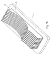
- FIG. 1a shows an inventive embodiment of a first cooling module.
- the first cooling module 1 consists of a module plate 2, on the underside of a molding is provided, which is formed as a plurality of parallel extending catch ribs 3.
- FIG. 1b is the first cooling module shown from below.
- the parallel locking ribs 3 have a tapering away from the module plate 2 thickness.
- the catch ribs 3 are designed congruent to each other and are made with the module cover 2 in one piece, in particular by sand casting or die casting, in aluminum.
- the catch ribs 3 are made of aluminum flat material separately and then connected by welding with the module plate 2 also made of aluminum.
- the catch ribs 3 and the module plate 2 are made of a metallic alloy, for example steel or copper or alloys of both.
- connection openings 10 are provided, which each open into a groove end 11 of the coolant groove 9.
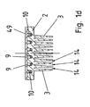
- Figure 1c shows a longitudinal section through the first cooling module 1.
- the sectional plane intersects the side surface of a gutter 3 approximately at mid-height.
- the Fangrippe 3 has three circular indentations 4, 5 and 6, which are separated by the circular intersection points 7 and 8.
- the radii of the circular indentations 4, 5 and 6 and the depth of their arching into the catching rib 3 are determined by the constructional and geometric conditions at the place of use of the first cooling module on a transmission, in particular by the radius and the position of the gears of the transmission.
- the three-part design shown advantageously has the effect that the cooling module can be used for different gear sets in the same gear housing.
- two or fewer or more than three circular bulges are provided, which are subdivided by circular intersections.
- slot-shaped interruptions running away from the module plate 2 are carried out on the catch ribs 3.
- Figure 1c also shows a portion of the coolant groove 9 with the groove bottom elevations 12.
- These groove bottom elevations 12 are designed as a rounded steps pillow-shaped, wherein the steps are arranged at equal intervals on the groove bottom.
- the groove bottom is wave-shaped, and / or the elevations are arranged at regular or irregular intervals, or the groove bottom is flat and thus designed without elevations.
- the groove bottom elevations have the effect that a liquid flowing in the coolant groove 9, for example a coolant, assumes a turbulent flow behavior, and thus has a good mixing, in particular with regard to the temperature distribution in the liquid.
- An aperture 17 connects the in Figure 1c shown portion of the coolant groove 9 with the adjacent portion of the coolant groove. 9
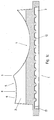
- Figure 1d shows a cross section through the first cooling module 1, on which a gear cover 49 is mounted.
- the coolant groove 9 forms a closed meandering channel through which coolant can flow, and which is connected to the outside only via the connection openings 10.
- the catch ribs 3 delimit collecting spaces 14, by means of which oil can be absorbed by the gear stages or the gear wheels when the cooling module is used according to the invention on a gear mechanism.
- the distance between the catch ribs is advantageously chosen so that the collecting spaces 14 formed by the catch ribs 3 each have a cross-section which is about as large as the Cross section of a catch rib 3.
- the inclination of the side surfaces of the catch ribs 3 relative to the module plate 2, the thickness of the catch ribs and the distance between the catch ribs are advantageously selected according to the specifications of the manufacturing process, such as sand casting or die casting.
- the distance between the ribs to each other is smaller or larger than the thickness of the catch ribs.
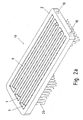
- FIG. 2a shows a further embodiment of a second cooling module according to the invention.
- the second cooling module 19 consists of a module plate 2, which on its underside have a shape in the form of catching fingers 20.
- the module plate 2 has a coolant groove 9 and connection openings 10 and is identical to the module plate of FIGS. 1a to 1d , thus, a cheap production of cooling modules in different variants, with catch ribs and / or catching fingers, allows.
- the second cooling module 19 is produced by the aluminum casting process.
- FIG. 2b shows the underside of the second cooling module 19.
- the catching fingers 20 are arranged in parallel longitudinal and transverse rows, so that continuous, parallel streets are formed in at least two directions.
- the catching fingers are arranged according to other regular or irregular patterns.
- the catching fingers 20 define catchment areas 21, by means of which, when the second cooling module is used according to the invention, oil can be taken up on a gear of its gear stages or its gear wheels in different directions, in particular obliquely or mutually perpendicular directions. This is advantageous over the embodiment according to FIG. 1a in which the catchment areas 14 mark a single direction.
- the catching fingers 20 have a round cross section with respect to their length, and they taper towards their end.
- the catching fingers in cross-section the shape of a polygon, in particular a three- or quadrilateral on.
- the shape of the cross-sectional area is oriented advantageously on the symmetry of the arrangement of the catching fingers on the module plate.
- the catch fingers can be manufactured together with the module plate with simple, inexpensive separation processes from a block.
- Figure 2c shows a longitudinal section through the in FIG. 2a shown second cooling module.
- the ends of the catching fingers 20 form an envelope in the longitudinal direction of the second cooling module 19, which describes three circular indentations. These circular indentations merge into conceptual circular intersections 22, 23.
- the radii of the circular indentations and the depth of their arching into the plane spanned by the catching fingers become due to the structural and geometric conditions at the place of use of the second cooling module on a transmission, in particular by the radius and the position of the rotating parts, such as gears, cyclo discs, eccentric discs or the like, of the transmission.
- two or fewer or more than three circular bulges are provided, which are subdivided by circular intersections.
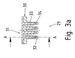
- FIG. 3a shows a cross section and FIG. 3b a longitudinal section along the section AA through a further inventive embodiment of a third cooling module.
- the third cooling module 29 consists of a module base 30 and a module top 31.
- the module base 30 comprises a plate and mutually parallel hollow ribs 32, in which corresponding solid ribs 33 of the module body 31 are arranged when the module top 31 on the module base 30 in the manner shown is attached.
- the longitudinal profile of the hollow ribs 32 after FIG. 3b describes an envelope, that of the catch ribs of the first cooling module 1 from Figure 1c like.
- the hollow ribs 32 and the solid ribs 33 form in the assembled position, as in FIG. 3b shown, in each case a coolant channel 34.
- These coolant channels 34 are connected via passages 35 so that a total of a meandering in two directions coolant channel is formed.
- the ends of the meandering coolant channel open out via two connection openings 36.
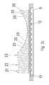
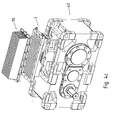
- FIG. 4a shows a use according to the invention of a first cooling module FIG. 1 a to 1 in a transmission 40, which comprises a housing 41 in monobloc construction, that is made of a single casting, with an opening 47.
- gears 45 are arranged on shafts. These gears 45 are accessible via the opening 47 for the purpose of assembly, inspection, maintenance or oil replacement.
- the opening is thus dimensioned such that the largest intended gear or Veriereteil is passed through them.
- the transmission in which the cooling module 1 is used, advantageously determines the structural dimensions of the cover 47 and thus of the cooling module 1.
- the length of the cover is approximately 30 cm in the exemplary embodiment described here. In other embodiments, this length is between 5 cm and 2 m.
- a shaft is mounted as a driving shaft 42 via a bearing in the housing 41, a cover 43 covers the end of the driven shaft of the transmission, which is led out of the housing 41 on the rear side, not shown.
- the opening 47 is closable with a housing cover 49, which is fastened by screws 52, which are screwed into threaded bores 57.
- the housing cover 49 is in a fixed position flat on the housing flange 51.
- sealing means between the housing flange 51 and housing cover 49 are provided which seal the interior of the housing 41 inwardly and outwardly, so that no oil can escape and no impurities can pass from the outside into the oil.
- the seal is effected by means of a metal adhesive, for example Loctite, which is applied to the flange surfaces.
- the seal is effected by an O-ring or paper seal circulating on the flange surface.
- Such a seal can be improved by a provided on the flange surfaces spring-groove system.
- a first cooling module 1 between housing flange 51 and housing cover 49 providable for this purpose, the underside of the module plate 2 of the cooling module 1 is placed on the housing flange 51.
- the module plate 2 has boreholes 58 which fit in arrangement and diameter to the threaded holes 57.
- the housing cover 49 can be fastened together with the first cooling module 1 via the screws 52 on the gear housing 41 by the screws 52 are inserted through the holes 58 and screwed into the threaded holes 57.
- a module flange surface 53 is provided, which forms a sealed closure of the interior of the transmission housing 41 with the housing cover 49.
- the necessary sealing means are not shown for the sake of simplicity.
- the underside of the module plate 2 with the housing flange 51 forms a tight seal of the interior.
- the coolant groove 9 is sealed in the module plate 2 to the outside so tightly that coolant, such as a cooling fluid such as water or oil, can flow in the channel thus formed without leaking.
- the necessary sealing means are not shown for the sake of simplicity. They are preferably provided on the surface of the module plate 2, but are also at least partially providable on the underside of the housing cover 49.
- On a side wall of the cooling module connecting devices in the form of two connection couplings 55 are provided. These connection couplings 55 run in the mounted position of the cooling module 1 tangentially to the outer surface of the transmission housing 41. Thus, the connection couplings 55 and connected thereto lines are protected by the cooling module 1 from damage. Coolant flows from a coolant circuit into the coolant groove 9 through a first connection coupling 55, and coolant flows from the coolant groove 9 back into the coolant circuit through a second connection coupling 55.
- the housing cover 49 is advantageously made of aluminum.
- the housing cover is made of steel or stainless steel and / or has at least on its side facing the coolant groove side corrosion-resistant and / or coolant-resistant coating, for example a paint or a plastic coating on.
- the plastic coating additionally causes the sealing of the connection of housing cover with cooling module.
- the catch ribs 3 of the first cooling module 1 protrude into the interior of the housing 41 through the imaginary boundary surface of the housing interior spanned by the opening 47, that is to say in particular by the housing flange surface 51.
- the longitudinal profile of the catch ribs 3 follows in the mounted position of the first cooling module 1 the shape of the gears 45, for which circular indentations are formed in the catch ribs 3.
- the number and shape of these circular indentations is chosen.
- the gears for the various gear ratios with which the housing 41 can be equipped are not inhibited in their intended movement by the catch ribs 3, on the other hand, the catch ribs 3 as closely as possible at least partially follow the swept by the gears area to the wheels to be able to absorb thrown off oil well.
- the distance between the catch ribs is chosen with particular regard to the viscosity of the oil so that the gears are not noticeably slowed down in their intended movement by located between catch ribs and gears oil.
- catch ribs 3 As advantageous, a three-part design of the catch ribs 3 in the illustrated manner Figure 1c Other embodiments of the catch ribs 3 are also included in the invention. For example, it is possible to project the catch ribs 3 laterally into the region of the housing interior to the left of the opening 47, as a result of which, in particular, the gearwheel on the driving shaft 42 is better covered.
- cooling fins are uneven and partially extend in areas adjacent gear 45th
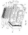
- FIG. 4b shows the inventive use of another embodiment of a passive cooling module.
- a passive cooling module 60 is tightly mounted on the housing flange 51 of the transmission 40.
- the passive cooling module 60 has on its underside parallel extending Fangrippen 3, as in FIG. 4a protrude described in the interior of the transmission case 41. On its upper side, the passive cooling module 60 has parallel cooling fins 62.
- the cooling fins 62 are advantageously designed to be congruent to each other.
- the passive cooling module 60 is made in two parts, consisting of an upper part with cooling fins 62 and a lower part with catch ribs 3.
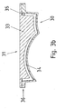
- Such an embodiment shows FIG. 6 , left side view and right side cross section.
- Upper and lower parts are connected to one another at a contact surface 110.
- the contact surface is additionally coated with a thermal paste.
- the passive cooling module 60 is produced in one piece, that is to say in particular from a single cast.
- the catching ribs 3 receive oil spun off the gearwheels 45, whereby heat is transported from the gearbox 40 to the catching ribs 3.
- the latter pass the heat via the body of the passive cooling module 60 to the cooling fins 62, which finally release the heat to the environment, for example air.
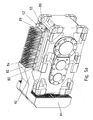
- FIG. 4c shows a further example of use of a cooling module according to the invention.
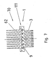
- a first module cover 70 having on its upper side parallel cooling fins 62.
- Such a cooling module with module cover shows FIG. 7 in cross section.
- the contact surface 111 which connects the first module cover 70 with the first cooling module 1, has sealing means, not shown, in order to close off the coolant groove 9 to the outside.
- the intended use of the first cooling module 1 is carried out as in FIG. 4a described.
- the cooling capacity is additionally increased by the cooling ribs 62 provided on the module cover, via which heat can be emitted to the environment.
- the safety is increased, because even in case of failure of the coolant circuit emergency cooling can be done via the cooling fins 62.
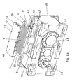
- FIG. 4d shows a further inventive use of a cooling module on a bevel gear.
- Oil module 80 is placed on this a coolant module 82 and on this a second module cover 84.
- Oil module 80, coolant module 82 and second module cover 84 each have corresponding holes 58 through which screws 52 are feasible to connect the modules (80, 82) and the lid 84 with the housing 41.
- the screws engage in threaded holes 57.
- Each Screw 52 advantageously causes the connection of all modules (80, 82) and the lid 84 with the housing 41 alike.
- the oil module 80 differs from the first cooling module 1 FIG. 1 a and 4a in that instead of the connection couplings 55 dummy plugs 86 are provided which close the connection openings 10, and that in addition to the underside of the module plate 2 holes are provided, which open via the closed connection openings 10 in the groove ends 11.
- the piping is formed from extending in the housing and outside of the housing tubes through which, for example, as a pressure circulation lubrication, in particular for gear or bearing lubrication, oil is pumped.
- the pump can be provided as a wave pump or as an electrically driven pump, which is preferably fastened to the outside of the transmission housing 41.
- the piping and / or the pump additionally have oil filters.
- the piping comprises a nozzle through which oil is passed or injected by the pressure circulation lubrication on the catch ribs 3.
- fittings 88 are formed as bores having additional sealing means.
- the coolant module 82 in FIG. 4d differs from the first cooling module 1 after FIG. 1a and 4a in that catch ribs 3 are not provided.
- a cooling medium circuit can be connected via connection couplings, via which heat can be removed from the oil module 80.
- the second module cover 84 in FIG. 4d has on its upper side on cooling fingers 89, which are arranged in longitudinal and transverse rows. Heat can be released from the coolant module 82 to the environment, in particular in air, via the cooling fingers 89.
- the bevel gear in FIG. 4d has on a front side, the Eintriebsseite 90 a driving shaft on which a fan 91 is mounted.
- the air moved by the fan 91 is partially directed by an air guiding device 92 onto the cooling fingers 89 of the second module cover 84, as a result of which a further increased cooling power can be achieved at the transmission.
- no fan is provided. Opposite the first module cover 70 of FIG. 6 In this case, cooling fingers 69 cause air to convectively flow in more than one direction. Thus, depending on the orientation of the transmission in the room - the design - improved heat dissipation achievable, even without a fan.
- FIG. 5a shows the device after FIG. 4d in assembled form.
- FIG. 5b shows a longitudinal section through a section of in FIG. 5a illustrated device.
- the longitudinal profile of the catch ribs 3 follows with its circular concavity 4 of the shape of the gear 45.
- the circular indentations 5, 6 are formed so that with a longitudinal profile enough space for different gears 46, but still thrown off oil is well received.
- a distance of the catch ribs of the gears of about 5mm has been found to be particularly advantageous for receiving the oil, but within the scope of manufacturing tolerances and smaller clearances conceivable
- Oil module 80, coolant module 82 and second module cover 84 form an oil passage 100 and a coolant passage 102.
- oil is pumped through the oil passage 100 via the pump of pressure circulation lubrication.
- Coolant is pumped through the coolant channel 102 via connection couplings 55 from a cooling circuit.
- a fan 91 guides air over the cooling fingers 89 via an air guiding device 92.
- the device after FIG. 4d . 5a and 5b thus forms a variety of ways in which heat from the transmission to the environment can be transported, From gears 45, 46 on thrown-off oil to catch ribs 3 and on to the oil module 80; from the oil sump via pipes 95 to the oil module 80; from the oil module 80 to the coolant module 82; from the coolant module 82 via the coolant in the coolant channel 102 to the coolant circuit; from the coolant module 82 via the second module cover 84 to the ambient air.
- a first module cover 70 is provided instead of the second module cover 84.
- the housing cover 49 is provided instead of the second module cover 84. In this case, at least the spoiler 92 can be omitted.
- FIGS. 4a to 4d show exemplary embodiments of cooling devices, which can be composed particularly advantageous from a kit.
- the opening 47 is designed as an interface for connecting to the various cooling modules or modules or covers.
- the housing cover which is mounted on the opening of a transmission without cooling device according to the invention, can be used to cover the coolant groove in a module additionally used for improving the cooling.
Abstract
Description
Die Erfindung betrifft einen Kühler für Getriebe, ein Getriebe mit Kühlvorrichtung, einen Baukasten von Getriebekühlvorrichtungen und eine Baureihe von Getrieben.The invention relates to a radiator for transmission, a transmission with cooling device, a kit of transmission cooling devices and a series of gearboxes.
Aus der
Aus der
Aus der
Aus der
Aus der gattungsgemässen
Aus der
Aus der
Der Erfindung liegt die Aufgabe zugrunde, ein Getriebe so weiterzubilden, dass die Getriebekühlung verbessert ist.The invention has the object of developing a transmission so that the transmission cooling is improved.
Erfindungsgemäß wird die Aufgabe bei dem Kühlmodul für ein Getriebe nach den in Anspruch 1 angegebenen Merkmalen gelöst.According to the invention, the object is achieved in the cooling module for a transmission according to the features specified in claim 1.
Von Vorteil ist dabei, dass eine Verbesserung des Wärmeabtransportes aus dem Getriebeinneren mittels einer vergrößerten Oberfläche im Raumbereich des Ölstroms zwischen dem Teil oder den Teilen und dem Gehäuse vorsehbar ist. Somit ist der Innenraum des Getriebes von einer Kühlvorricht,ung besser ausnutzbar. Denn der Ölstrom innerhalb des Getriebes ist an derjenigen Oberfläche des Kühlmoduls vorbeileitbar, welche mittels der ins Getriebeinnere hineinragenden Ausformung vergrößert ist. Dadurch ist ein geringerer Abstand zwischen Wärmequelle und Kühlmodul-Oberfläche erreichbar, und der Wärmeübergang ist verbessert. Außerdem ist der Ölstrom besser ausgenutzt. Denn der wesentliche Anteil des Ölstromes ist nun derart leitbar, dass er in Kontakt kommt mit der Oberfläche zum Wärmeableiten. Insbesondere ist die Ausformung vorteilhaft derart nahe an die Verzahnteile heranführbar, dass nur unwesentliche Teile des Ölstroms verloren gehen für die Wärmeableitung ans Kühlmodul. Außerdem ist ein Schmiermittel verwendbar, das höhere Viskosität aufweist als Öl, beispielsweise Schmierfett oder Fett. Ein solcher Schmierstoff klebt zumindest teilweise am Verzahnteil, solange die Temperatur des Getriebes niedrig ist. Mittels der Erfindung können die nahe herangeführten Ausformungen dennoch mit diesem Schmierstoffanteil in Kontakt kommen.The advantage here is that an improvement in the heat dissipation from the inside of the gearbox by means of an enlarged surface in the space region of the oil flow between the part or parts and the housing is providable. Thus, the interior of the transmission of a Kühlvorricht, is better exploitable. Because the flow of oil within the transmission can be vorbeileitbar on that surface of the cooling module, which by means of the ins Geared inside projecting shape is increased. As a result, a smaller distance between the heat source and the cooling module surface can be achieved, and the heat transfer is improved. In addition, the oil flow is better utilized. Because the essential part of the oil flow is now so conductive that it comes into contact with the surface for heat dissipation. In particular, the shape is advantageously so close to the gear teeth approachable that only negligible parts of the oil flow lost for the heat dissipation to the cooling module. In addition, a lubricant having higher viscosity than oil, such as grease or grease, is usable. Such a lubricant at least partially adheres to the gear portion, as long as the temperature of the transmission is low. By means of the invention, the closely approached formations can still come into contact with this lubricant portion.
Bei einer weiteren vorteilhaften Ausgestaltung umfasst das Kühlmodul ein Gussteil, wobei im Gussteil ein Raumbereich für strömendes Kühlmittel, insbesondere Öl oder Luft oder Wasser, vorgesehen ist, und wobei am Gussteil ins Getriebeinnere gerichtete Kühlrippen und/oder Kühlfinger angebracht sind, insbesondere mit dem Gussteil einstückig ausgeformte oder an das Gussteil angeschweißte. Das Kühlmodul weist somit eine in Längsrichtung des Gussteils variable Dicke auf. Von Vorteil ist dabei, dass zwei getrennte Raumbereiche vorsehbar sind, ein erster für ein strömendes Kühlmittel, beispielsweise Luft, Wasser oder Öl, und ein zweiter, im Getriebeinneren gelegener, für den Kontakt von Kühlrippen oder Kühlfingern mit im Getriebegehäuse strömendes Öl, also Schmieröl. Somit ist vorteilhaft ein dickes Metallteil als Gussteil vorsehbar, wodurch das Kühlmodul robust ist gegenüber mechanischen Beanspruchungen. Von Vorteil ist weiterhin, dass durch die Trennung der zwei Raumbereiche redundante Sicherheit erreichbar ist gegen Vermischung von Kühlmittel und Schmieröl. Denn selbst wenn eine Dichtung des Raumbereichs für das Kühlmittel undicht werden sollte, so würde das Kühlmittel nicht in das Getriebeinnere eintreten können sondern außerhalb des durch das Gussteil abgeschlossenen Getriebeinneren fließen.In a further advantageous embodiment, the cooling module comprises a casting, wherein in the casting a space area for flowing coolant, in particular oil or air or water, is provided, and wherein the casting gear inside the cooling fin and / or cooling fingers are mounted, in particular integrally with the casting molded or welded to the casting. The cooling module thus has a variable thickness in the longitudinal direction of the casting. The advantage here is that two separate space areas are providable, a first for a flowing coolant, such as air, water or oil, and a second, located inside the gear, for the contact of cooling fins or cooling fingers with flowing in the gearbox oil, so lubricating oil. Thus, advantageously, a thick metal part is providable as a casting, whereby the cooling module is robust against mechanical stresses. Another advantage is that the separation of the two spatial areas redundant security can be achieved against mixing of coolant and lubricating oil. Because even if a seal of the space area for the coolant should be leaking, the coolant would not be able to enter the gearbox interior but would flow outside of the geared interior enclosed by the casting.
Bei einer weiteren vorteilhaften Ausgestaltung folgt die dem Getriebeinneren zugewandte Ausformung des Kühlmoduls der Form eines rotierenden Teils oder mehrerer rotierender Teile des Getriebes derart, dass Wärme aus dem Raumbereich, insbesondere im Wesentlichen aus dem gesamten Raumbereich, des Ölstroms zwischen dem oder den Teilen und dem Gehäuse abtransportierbar ist. Somit ist vorteilhaft zur Verbesserung der Wärmeabfuhr vom Öl an die Getriebeumgebung in Raumbereichen des Ölstroms Wärme durch die Ausformung aufnehmbar. Besonders vorteilhaft wird ein Folgen der Form eines rotierenden Teils des Getriebes erreicht, wenn um das rotierende Teil ein konzentrischer Kreis oder eine konzentrische Ellipse mit kleiner Exzentrizität gezeichnet werden kann, der oder die mit der mathematisch idealisierten Oberfläche der Ausformung gemeinsame Punkte hat, der oder die aber das mathematisch Innere der Ausformung nicht schneidet. Die Form der Ausformung, und also auch das Folgen der Form des rotierenden Teils, ist vorteilhaft derart vorgesehen, dass der durch das rotierende Teil erzeugte Schmierstoffstrom oder Ölstrom zur Wärmeableitung möglichst vollständig in Kontakt bringbar ist mit der Oberfläche der Ausformung. Dabei soll der Strömungswiderstand für den Strom klein gehalten sein.In a further advantageous embodiment, the formation of the cooling module facing the inside of the gear unit follows the shape of a rotating part or several rotating parts of the gear unit in such a way that heat from the space area, in particular substantially from the entire space area, of the oil flow between the part or parts and the housing can be transported away. Thus, it is advantageous for improving the heat dissipation from the oil to the transmission environment in space regions of the oil flow heat absorbable by the shaping. Particularly advantageously, a tracking of the shape of a rotating part of the transmission is achieved if around the rotating part a concentric circle or a concentric ellipse with small eccentricity can be drawn, which or has common points with the mathematically idealized surface of the molding, the or but the mathematical interior of the formation does not intersect. The shape of the molding, and thus also the consequences of the shape of the rotating part, is advantageously provided such that the lubricant flow or oil flow generated by the rotating part for heat dissipation as completely as possible is brought into contact with the surface of the molding. In this case, the flow resistance for the stream should be kept small.
Bei einer weiteren vorteilhaften Ausgestaltung ist die Form der Ausformung so gewählt, dass einerseits die Zahnräder oder Verzahnteile, beispielsweise Zykloscheiben oder Exzenterscheiben, des Getriebes für die verschiedenen Übersetzungszahlen, mit denen das Getriebe ausrüstbar ist, in ihrer bestimmungsgemäßen Bewegung nicht durch die Ausformung gehemmt werden, andererseits die Ausformung möglichst dicht zumindest teilweise dem von den rotierenden Teilen, insbesondere den Zahnrädern, überstrichenen Bereich folgt, um von den rotierenden Teilen, insbesondere den Zahnrädern, weggeschleudertes Öl gut aufnehmen zu können. Von Vorteil ist dabei, dass der Abstand der Ausformung zu einem rotierenden Teil oder mehreren rotierenden Teilen so klein wie möglich ist. Der minimale Abstand der Ausformung zu den rotierenden Teilen ist dabei hauptsächlich durch die Fertigungstoleranzen des Getriebegehäuses und des Kühlmoduls bestimmt. Bei Getrieben mit kleiner durchgeleiteter Leistung ist zusätzlich vorteilhaft durch Wahl des Abstandes zu den rotierenden Teilen erreichbar, dass der Wirkungsgrad des Getriebes nicht wesentlich durch Reibung des Öls zwischen Ausformung und rotierenden Teilen vermindert wird, bedingt insbesondere beim Anlaufen bei niedrigen Temperaturen durch Verkleben des Öls. Von Vorteil ist dabei, dass eine Baureihe von Getrieben, deren Getriebe-Varianten sich lediglich durch die Auswahl von Zahnrädern in ihrer Übersetzungszahl unterscheiden, mit einem einheitlichen Kühlmodul ausrüstbar ist.In a further advantageous embodiment, the shape of the shape is selected so that on the one hand, the gears or toothed parts, such as cyclo discs or eccentric, the transmission for the various gear ratios with which the gear is equipped, are not inhibited in their intended movement by the formation, on the other hand, the formation as closely as possible at least partially followed by the rotating parts, in particular the gears, swept area to be able to absorb from the rotating parts, in particular the gears, flung oil well. The advantage here is that the distance of the molding to a rotating part or more rotating parts is as small as possible. The minimum distance of the molding to the rotating parts is mainly determined by the manufacturing tolerances of the gear housing and the cooling module. In transmissions with small transmitted power is additionally advantageous by selecting the distance to the rotating parts achievable that the efficiency of the transmission is not significantly reduced by friction of the oil between molding and rotating parts, especially when starting at low temperatures by sticking of the oil. The advantage here is that a series of gearboxes whose transmission variants differ only by the selection of gears in their gear ratio, can be equipped with a single cooling module.
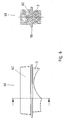
Bei einer weiteren vorteilhaften Ausgestaltung umfasst die Schnittstelle zur dicht abschließenden Verbindung des Kühlmoduls mit dem Getriebe eine Dichtung, wobei insbesondere die Ausformung durch die von der Dichtung berandete Minimalfläche ins Innere des Getriebes ragt. Die von der Dichtung berandete Minimalfläche dient dabei zur Trennung von Innerem und Äußerem des Getriebegehäuses bezüglich der zur Schnittstelle gehörenden Öffnung. Die Minimalfläche ergibt sich, indem die Dichtung auf eine idealisierte geschlossene Linie reduziert wird, die die Öffnung umläuft und somit beschreibt, und indem in die Linie ein Teilstück einer Seifenblase eingesetzt wird, deren Rand durch die geschlossene Linie gebildet wird und die ansonsten sich selbst überlassen wird. Mit dem Kühlmodul ist also allgemein eine Ausnehmung, insbesondere Öffnung, im Getriebegehäuse verschließbar, deren Umrandung eine Minimalfläche begrenzt, durch welche die Ausformung ins Innere des Getriebes hindurch ragt. Somit wird vorteilhaft der Innenraum des Getriebes, der sich an die Schnittstelle anschließt, von dem Kühlmodul zur Wärmeaufnahme genutzt.In a further advantageous embodiment, the interface for tightly sealing connection of the cooling module with the gearbox comprises a seal, wherein in particular the formation protrudes through the surface bounded by the seal into the interior of the transmission. The bordered by the seal minimal surface serves to separate the inside and outside of the gear housing with respect to the interface belonging opening. The minimum area is obtained by reducing the seal to an idealized closed line which circumscribes and thus describes the opening, and by inserting into the line a portion of a bubble whose edge is formed by the closed line and which otherwise leave itself becomes. With the cooling module is thus generally a recess, in particular opening, closable in the gear housing, the border defines a minimum surface through which the molding projects into the interior of the transmission through. Thus, advantageously, the interior of the transmission, which adjoins the interface, used by the cooling module for heat absorption.
Bei einer weiteren vorteilhaften Ausgestaltung umfasst die Ausformung Rippen, die insbesondere schlitzförmige Unterbrechungen aufweisen, wobei der äußere Rand der Rippen der Form eines rotierenden Teils oder mehrerer rotierender Teile des Getriebes folgt. Somit bilden die Rippen vorteilhaft Oberflächen aus, die einerseits den Ölstrom führen und andererseits aus dem Ölstrom Wärme aufnehmen. Der Abstand der Rippen untereinander ist vorteilhaft gemäß der Viskosität des Schmieröls minimal derart wählbar, dass ein Strömen des Öls in den Zwischenräumen zwischen den Rippen mit geringem Strömungswiderstand erfolgt. Der Abstand der Rippen und die Dicke der Rippen wird insbesondere vorteilhaft durch das vorgesehene Fertigungsverfahren bestimmt.In a further advantageous embodiment, the formation comprises ribs, which in particular have slot-shaped interruptions, wherein the outer edge of the ribs follows the shape of a rotating part or a plurality of rotating parts of the transmission. Thus, the ribs advantageously form surfaces which, on the one hand, carry the oil flow and, on the other hand, absorb heat from the oil flow. The distance of the ribs from each other is advantageously selected in accordance with the viscosity of the lubricating oil minimally such that a flow of the oil takes place in the spaces between the ribs with low flow resistance. The distance of the ribs and the thickness of the ribs is particularly advantageously determined by the intended manufacturing process.
Bei einer weiteren vorteilhaften Ausgestaltung umfasst die Ausformung mehrere Finger, wobei die Enden der Finger auf einer gedachten, mathematischen Linie oder Oberfläche liegen, die der Form eines rotierenden Teils oder mehrerer rotierender Teile des Getriebes folgt. Durch die Ausgestaltung der Ausformung als Finger, die vorzugsweise quer zu ihrer Längsrichtung einen runden Querschnitt aufweisen, wird gegenüber der Ausgestaltung als Rippen vorteilhaft erreicht, dass strömendes oder spritzendes oder geschleudertes Öl aus mehr als einer Richtung aufnehmbar ist. Somit ist der Wärmeübergang vom Öl an das Kühlmodul weiter verbessert, insbesondere wenn das Getriebe in einer weniger günstigen Lage eingesetzt wird, in der die Ölströmung lagebedingt nicht entlang der Rippenverlaufsrichtung erfolgt. Der Abstand der Finger untereinander ist vorteilhaft gemäß der Viskosität des Schmieröls so wählbar, dass ein Strömen des Öls in den Zwischenräumen zwischen den Rippen mit geringem Strömungswiderstand erfolgt.In a further advantageous embodiment, the molding comprises a plurality of fingers, wherein the ends of the fingers lie on an imaginary mathematical line or surface which follows the shape of a rotating part or a plurality of rotating parts of the transmission. Due to the configuration of the shape as fingers, which preferably have a round cross section transverse to their longitudinal direction, it is advantageously achieved with respect to the embodiment as ribs that flowing or spraying or spun oil can be received from more than one direction. Thus, the heat transfer from the oil to the cooling module is further improved, especially when the transmission is used in a less favorable position, in which the oil flow is due to the position not along the Rippenverlaufsrichtung. The distance of the fingers from each other is advantageously selected according to the viscosity of the lubricating oil so that a flow of the oil takes place in the spaces between the ribs with low flow resistance.
Bei einer weiteren vorteilhaften Ausgestaltung sind die Rippen und/oder Finger hohl ausgebildet zur Aufnahme eines Kühlmittels, insbesondere Wasser. Von Vorteil ist dabei, dass durch Aufsetzen eines geeignet geformten Deckels die Rippen Kanäle ausbilden, in denen ein Kühlmittel, beispielsweise Wasser, besonders nahe am Ölstrom fließt und somit der Wärmeabtransport an die Umgebung weiter verbessert ist.In a further advantageous embodiment, the ribs and / or fingers are hollow for receiving a coolant, in particular water. It is advantageous that by placing a suitably shaped cover, the ribs form channels in which a coolant, such as water, flows particularly close to the oil flow and thus the heat dissipation to the environment is further improved.
Bei einer weiteren vorteilhaften Ausgestaltung folgt die Ausformung der Form eines rotierenden Teils des Getriebes auf mindestens einer gedachten kreisbogenförmigen Linie, wobei insbesondere der Radius des Kreisbogens durch den Radius des rotierenden Teils bestimmt ist, und/oder die Ausformung sich in Bereiche neben den Seitenflächen von Zahnrädern des Getriebes erstreckt. Somit ist vorteilhaft ein besonders wirkungsvolles Aufnehmen der Ölstroms und eine besonders gute Ausnutzung des Getriebeinnenraums erreichbar.In a further advantageous embodiment, the shaping of the shape of a rotating part of the transmission follows at least one imaginary arcuate line, wherein in particular the radius of the circular arc is determined by the radius of the rotating part, and / or the formation in areas adjacent to the side surfaces of gears of the transmission extends. Thus, a particularly effective absorption of the oil flow and a particularly good utilization of the transmission interior is advantageously achievable.
Bei einer weiteren vorteilhaften Ausgestaltung ist das Kühlmodul aus Aluminium oder Stahl oder Kupfer oder einer metallischen Legierung hergestellt, insbesondere im Druckguss- oder Sandgussverfahren, und/oder es ist vorgesehen, dass die Ausformung mit dem Kühlmodul stoffschlüssig, insbesondere durch Kleben oder Schweißen, verbunden ist. Somit ist vorteilhaft eine kostengünstige, unaufwendige Fertigung des Kühlmoduls erreichbar.In a further advantageous embodiment, the cooling module made of aluminum or steel or copper or a metallic alloy, in particular die casting or sand casting method, and / or it is provided that the molding with the cooling module is materially bonded, in particular by gluing or welding , Thus, an inexpensive, inexpensive production of the cooling module is advantageously achievable.
Bei einer weiteren vorteilhaften Ausgestaltung orientiert sich die Gestalt der Querschnittsfläche der Finger, also der Schnittfläche quer zu Längsrichtung der Finger, an der Symmetrie der Anordnung der Finger auf dem Kühlmodul, wobei die Finger insbesondere durch ein spanendes Verfahren, insbesondere Fräsen, hergestellt sind. Somit ist vorteilhaft eine kostengünstige, einfache Fertigung der Rippen mit wenig Aufwand erreichbar. Es sind vorteilhaft je nach Symmetrietyp, also der Zähligkeit der diskreten Drehsymmetrie, die bei idealisierter, hypothetischer unendlicher Ausdehnung das Anordnungsgitter für die Finger in sich selbst überfährt, dreieckige, viereckige oder vieleckige Querschnitte vorsehbar.In a further advantageous embodiment, the shape of the cross-sectional area of the fingers, ie the cross-sectional area transverse to the longitudinal direction of the fingers, based on the symmetry of the arrangement of the fingers on the cooling module, the fingers are made in particular by a cutting process, in particular milling. Thus, a low-cost, simple production of the ribs is advantageously achievable with little effort. Depending on the type of symmetry, that is to say the degree of discrete rotational symmetry which, in the case of an idealized, hypothetical infinite extent, overcomes the arrangement grid for the fingers in itself, it is advantageous to provide triangular, quadrangular or polygonal cross sections.
Vorzugsweise erstreckt sich die Ausformung entlang einer gedachten Ebene, die transversal, insbesondere rechtwinklig, zu einer Wellenachse des Getriebes, insbesondere einer Wellenachse des rotierenden Teils, verläuft. Von Vorteil ist dabei, dass die Strömung des von dem rotierenden Teil weggeschleuderten Öls nicht wesentlich behindert wird und dass gleichzeitig eine große Oberfläche zum Wärmeübergang von strömendem Öl auf das Kühlmodul bereitgestellt wird.Preferably, the formation extends along an imaginary plane which extends transversely, in particular at right angles, to a shaft axis of the transmission, in particular a shaft axis of the rotating part. The advantage here is that the flow of the ejected from the rotating part oil is not significantly hindered and that at the same time a large surface for the heat transfer of flowing oil is provided to the cooling module.
Bei einer weiteren vorteilhaften Ausgestaltung ist das Kühlmodul für ein Getriebe als Deckel zum Verschließen einer Öffnung des Getriebegehäuses auf das Getriebegehäuse aufsetzbar, wobei das Kühlmodul als Gussteil ausgeführt ist und auf seiner Außenseite eine Nut aufweist. Besonders vorteilhaft ist das Kühlmodul zum Verschließen der Montageöffnung vorsehbar, durch die bei der Getriebemontage die Verzahnteile ins Innere des Getriebes einbringbar sind. Das Gussteil weist Anschlussvorrichtungen für einen Kühlkreislauf auf, und die Enden der Nut sind mit den Anschlussvorrichtungen verbunden. Die Nut ist vorteilhaft mäandrierend ausführbar. Somit ist ein externer Kühlkreislauf für Wasser oder ein anderes Kühlmittel vorsehbar, der sicher trennbar ist vom Getriebeinnenraum. Die sichere Trennung beruht darauf, dass der Abschluss des Kühlkreislaufs nach außen mit Mitteln erfolgt, die verschieden und räumlich getrennt sind von den Mitteln zum Abschluss des Getriebeinnenraums. Dies ist besonders vorteilhaft, da das Eintreten von Wasser in den Getriebeinnenraum und ein Vermischen mit Öl unbedingt zu vermeiden ist.In a further advantageous embodiment, the cooling module for a transmission as a cover for closing an opening of the transmission housing can be placed on the transmission housing, wherein the cooling module is designed as a casting and has on its outer side a groove. Particularly advantageously, the cooling module for closing the mounting hole is providable, through which the gear teeth in the gearbox installation in the interior of the transmission can be introduced. The casting has connection devices for a cooling circuit, and the ends of the groove are connected to the connection devices. The groove is advantageously meandering executable. Thus, an external cooling circuit for water or other coolant is providable, which is safely separable from the transmission interior. The safe separation is based on the fact that the completion of the cooling circuit to the outside with means that are different and spatially separated from the means for completing the transmission interior. This is particularly advantageous since the entry of water into the transmission interior and mixing with oil must be avoided at all costs.
Vorzugsweise ist die Anschlussvorrichtungen für einen Kühlkreislauf mit dem Gussteil einstückig ausgeführt sind. Die Anschlussvorrichtungen sind somit besonders vorzugsweise als Anschlussstutzen oder als Bohrungen in einem Anschlusskörper ausgebildet. Hierdurch ist eine besonders einfache Fertigung ermöglicht, und ein Kühlkreislauf ist einfach und schnell anschließbar. Die Gefahr von Leckagen ist zudem verhindert oder zumindest vermindert.Preferably, the connection devices for a cooling circuit with the casting are made in one piece. The connection devices are thus particularly preferably designed as connecting pieces or as bores in a connection body. As a result, a particularly simple production allows, and a cooling circuit is easy and quick to connect. The risk of leakage is also prevented or at least reduced.
Vorzugsweise verlaufen die Anschlussvorrichtungen in etwa tangential zur Oberfläche des Getriebegehäuses im Bereich der Öffnung. Von Vorteil ist bei der tangentialen Anordnung der Anschlussvorrichtungen, dass diese in der montierten Position des Kühlmoduls keine zusätzlich überstehenden Bauteile darstellen und von dem Kühlmodul geschützt werden. Somit ist die Gefahr einer Beschädigung des Kühlkreislaufs vermindert. Die Anschlussvorrichtungen sind besonders vorzugsweise so angeordnet, dass sie im Vergleich zu den baulichen Abmaßen des Kühlmoduls über der Öffnung des Getriebegehäuses keine zusätzliche Erhebung darstellen. Die Anschlussvorrichtungen umfassen ganz besonders vorzugsweise röhrenförmige Anschlussstücke, in welche oder auf welche die Kühlleitungen eines Kühlkreislaufs steckbar sind, und die Achsen dieser röhrenförmigen Anschlussstücke folgen in der Umgebung der Öffnung des Getriebegehäuses, die das Kühlmodul verschließt, in etwa tangential der Außenfläche des Getriebegehäuses. Von Vorteil ist dabei, dass eine seitlich angeordnete Anschlussmöglichkeit für Kühlleitungen geschaffen ist, die durch ihre Anordnung vor Beschädigungen geschützt ist.Preferably, the connection devices extend approximately tangentially to the surface of the transmission housing in the region of the opening. An advantage of the tangential arrangement of the connection devices that they do not represent additional protruding components in the mounted position of the cooling module and are protected by the cooling module. Thus, the risk of damage to the cooling circuit is reduced. The connection devices are particularly preferably arranged so that they do not constitute an additional elevation in comparison to the constructional dimensions of the cooling module above the opening of the transmission housing. The connecting devices particularly preferably comprise tubular connecting pieces into which or to which the cooling lines of a cooling circuit can be plugged, and the axes of these tubular connecting pieces follow in the vicinity of the opening of the gearbox housing, which closes the cooling module, approximately tangentially to the outer surface of the gearbox housing. The advantage here is that one laterally arranged connection possibility for cooling lines is created, which is protected by their arrangement from damage.
Vorzugsweise ist eine Anschlussvorrichtung für die Zuleitung und eine Anschlussvorrichtung für den Abfluss des Kühlkreislaufs vorgesehen. Beide Anschlussvorrichtungen sind in einer vorteilhaften Ausgestaltung an derselben Seite des Kühlmoduls angeordnet. Von Vorteil ist dabei, dass nur eine Seite, besonders vorzugsweise nur eine Stelle besonders vor Leckage durch Beschädigungen zu schützen ist.Preferably, a connection device for the supply line and a connection device for the outflow of the cooling circuit is provided. Both connection devices are arranged in an advantageous embodiment on the same side of the cooling module. The advantage here is that only one side, particularly preferably only one point is particularly protected against leakage by damage.
Bei einer alternativen Ausgestaltung sind die Anschlussvorrichtungen an gegenüberliegenden Seiten oder an benachbarten Seiten angebracht. Von Vorteil ist dabei, dass weitere Möglichkeiten für die Verlegung der Kühlleitungen am Gehäuse bereitgestellt sind. Somit ist die Führung der Kühlleitungen flexibler gestaltbar.In an alternative embodiment, the connection devices are mounted on opposite sides or on adjacent sides. The advantage here is that further possibilities for the installation of the cooling lines are provided on the housing. Thus, the leadership of the cooling lines is flexible designable.
Bei einer vorteilhaften Ausgestaltung ist das Kühlmodul auf eine Gehäuseflanschfläche der Öffnung des Kühlmoduls aufsetzbar, wobei die Modulflanschfläche und die Gehäuseflanschfläche dieselbe Gestalt aufweisen, insbesondere identisch ausgebildet sind. Von Vorteil ist dabei, dass der Deckel zum Verschließen der Öffnung des Getriebegehäuses wiederverwendbar ist zur Abdeckung des Kühlmoduls und insbesondere der Nuten im Kühlmodul. Somit wird auf einfache Weise und mit geringem Teileaufwand durch das Aufsetzen des Deckels ein Kühlmittelkanal gebildet.In an advantageous embodiment, the cooling module can be placed on a housing flange surface of the opening of the cooling module, the module flange surface and the housing flange surface having the same shape, in particular having the same design. The advantage here is that the cover for closing the opening of the transmission housing is reusable to cover the cooling module and in particular the grooves in the cooling module. Thus, a coolant channel is formed in a simple manner and with low parts costs by placing the lid.
Bei einer weiteren vorteilhaften Ausgestaltung weist der Boden der Nut Erhebungen, insbesondere kissenförmige und/oder wellenförmige und/oder in regelmäßigen Abständen angeordnete Erhebungen, auf. Die Erhebungen bewirken eine Veränderung der Nuttiefe in Nutverlaufsrichtung, also längs der Nut. Von Vorteil ist dabei, dass durch die Erhebungen ein turbulentes Strömen des Kühlmittels selbst bei verhältnismäßig geringen Strömungsgeschwindigkeiten, bei denen das Kühlmittel insbesondere ohne Erhebungen laminar fließen würde, erzwungen wird. Infolgedessen weist der Kühlmittelstrom eine gleichförmigere Temperaturverteilung auf, als dies bei laminarer Strömung der Fall wäre. Somit ist bei gleicher Kühlmittel-Durchsatzmenge ein verbesserter Wärmeabtransport erreichbar. Dies spart Kühlmittel und Energie und folglich Kosten.In a further advantageous embodiment, the bottom of the groove elevations, in particular pillow-shaped and / or wavy and / or arranged at regular intervals surveys on. The elevations cause a change in the groove depth in Nutverlaufsrichtung, ie along the groove. The advantage here is that by the surveys a turbulent flow of the coolant is enforced even at relatively low flow velocities at which the coolant would flow in particular without elevations laminar. As a result, the coolant flow has a more uniform temperature distribution than would be the case with laminar flow. Thus, with the same coolant flow rate, improved heat dissipation can be achieved. This saves coolant and energy and therefore costs.
Bei einer weiteren vorteilhaften Ausgestaltung umfasst das Getriebegehäuse eine Gehäuse-Schnittstelle zum Verschließen einer Öffnung mit einem Deckel, wobei das Kühlmodul auf seiner dem Getriebe abgewandten Seite eine äußere Verbindungs-Schnittstelle aufweist, wobei die äußere Verbindungs-Schnittstelle und die Gehäuse-Schnittstelle gleichartig, insbesondere identisch, ausgeführt sind, insbesondere dieselbe Gestalt aufweisen. Durch die Ausbildung und Verwendung von Schnittstellen zum mechanischen Verbinden lassen sich eine Vielzahl von Kühlvorrichtungen aus einer geringen Zahl von Einzelteilen zusammensetzen. Dies spart vorteilhaft Lagerhaltungs- und Konstruktionskosten. Unter Schnittstelle wird hier allgemein eine Liste von Merkmalen und/oder Mitteln verstanden, die einander entsprechend an zwei Teilen und/oder zwischen zwei Teilen vorgesehen sind, um zu bewirken, dass ein Zusammenfügen und/oder Verbinden dieser Teile auf definierte Weise erfolgt.In a further advantageous embodiment, the transmission housing comprises a housing interface for closing an opening with a cover, wherein the cooling module on its side facing away from the transmission has an external connection interface, wherein the external connection interface and the housing interface similar, in particular identical, are executed, in particular, have the same shape. Through the design and use of interfaces for mechanical connection, a plurality of cooling devices can be composed of a small number of individual parts. This advantageously saves storage and construction costs. The term "interface" as used herein generally refers to a list of features and / or means provided correspondingly on two parts and / or between two parts to cause the joining and / or joining of these parts to take place in a defined manner.
Bei einer weiteren vorteilhaften Ausgestaltung umfasst die Gehäuse-Schnittstelle und die äußere Verbindungs-Schnittstelle jeweils Dichtungsmittel. Somit wird vorteilhaft die Funktion des dichten Verbindens in die Verbindungs-Schnittstelle integriert. Die Dichtungsmittel haben hierbei die Aufgabe, das Innere des Getriebegehäuses gegen Staub, Schmutz und Wasser und gegebenenfalls Luft abzudichten, die Umgebung des Getriebes vor Öl abzuschirmen und gegebenenfalls das Austreten von Kühlmittel zu verhindern, insbesondere das Vermischen von Kühlmittel mit Öl im Getriebegehäuseinneren. Diese Dichtmittel sind vorzugsweise als O-Ringe oder Elastomertlächen oder Klebeverbindungen ausgebildet.In a further advantageous embodiment, the housing interface and the outer connection interface each comprise sealing means. Thus, advantageously the function of the tight connection is integrated into the connection interface. The sealant here have the task to seal the interior of the gear housing against dust, dirt and water and possibly air to shield the environment of the transmission from oil and possibly to prevent the escape of coolant, in particular the mixing of coolant with oil in the gear housing interior. These sealing means are preferably designed as O-rings or Elastomertlächen or adhesive joints.
Bei einer weiteren vorteilhaften Ausgestaltung weist das Kühlmodul auf seiner dem Getriebe zugewandten Seite eine innere Verbindungs-Schnittstelle auf, wobei die innere Verbindungs-Schnittstelle und die äußere Verbindungs-Schnittstelle gleichartig, insbesondere identisch, ausgeführt sind, insbesondere dieselbe Gestalt aufweisen. Somit lassen sich vorteilhaft Bearbeitungsschritte bei der Fertigung der Kühlmodule vereinfachen.In a further advantageous embodiment, the cooling module on its side facing the transmission on an inner connection interface, wherein the inner connection interface and the outer connection interface are similar, in particular identical, executed, in particular have the same shape. Thus, advantageous processing steps in the manufacture of the cooling modules can be simplified.
Bei einer weiteren vorteilhaften Ausgestaltung ist das Kühlmodul aus Aluminium oder Stahl oder einer metallischen Legierung, beispielsweise nichtrostender Stahl, gefertigt, insbesondere im Druckguss- oder Sandgussverfahren und/oder ist die Ausformung mit dem Kühlmodul stoffschlüssig, insbesondere durch Kleben oder Schweißen, verbunden. Von Vorteil ist dabei, dass Materialien verwendet werden, mit denen eine Fertigung einfach und kostengünstig entsprechend den Anforderungen durchführbar ist. Die Anforderungen umfassen insbesondere mechanische Stabilität gegenüber den Belastungen, denen das Getriebe beim Betrieb ausgesetzt ist, Gewicht, thermische Belastbarkeit bei Temperaturen von 100°C und höher und chemische Beständigkeit gegenüber dem Kühlmittel.In a further advantageous embodiment, the cooling module made of aluminum or steel or a metallic alloy, for example stainless steel, manufactured, in particular in die casting or sand casting and / or is the formation of the Cooling module cohesively, in particular by gluing or welding, connected. The advantage here is that materials are used with which a production is simple and inexpensive according to the requirements carried out. The requirements include, in particular, mechanical stability against the stresses to which the gearbox is exposed during operation, weight, thermal capacity at temperatures of 100 ° C and higher, and chemical resistance to the coolant.
Merkmale der Erfindung bei dem Getriebe mit Kühlvorrichtung sind, dass das Getriebegehäuse eine Öffnung aufweist, die mit einem Deckel verschließbar ist, wobei die Kühlvorrichtung ein Kühlmodul umfasst, und wobei das Kühlmodul räumlich zwischen dem Gehäuse und dem Deckel angeordnet ist und die Öffnung verschließt. Von Vorteil ist dabei, dass eine Kühlvorrichtung bei einem Getriebe einfach, flexibel und kostengünstig nachrüstbar ist, wobei insbesondere der Deckel der Öffnung an der die Kühlvorrichtung angebracht wird, an der Kühlvorrichtung wiederverwendet wird. Das spart Kosten bei der Nachrüstung. Insbesondere ist vorteilhaft ein separater Bereich am Getriebegehäuse zum Anbau einer Kühlvorrichtung verzichtbar, da eine mit einem Deckel verschließbare Öffnung ohnehin, beispielsweise zu Montage- oder Wartungszwecken, am Getriebegehäuse vorgesehen ist und erfindungsgemäß verwendbar ist.Features of the invention in the transmission with cooling device are that the transmission housing has an opening which is closable with a lid, wherein the cooling device comprises a cooling module, and wherein the cooling module is arranged spatially between the housing and the lid and closes the opening. The advantage here is that a cooling device in a transmission is simple, flexible and inexpensive to retrofit, in particular, the lid of the opening at which the cooling device is mounted, is reused to the cooling device. This saves costs for retrofitting. In particular, a separate area on the gear housing for mounting a cooling device is advantageously dispensable, since a closable with a lid opening anyway, for example for assembly or maintenance purposes, is provided on the gear housing and is used in the invention.
Merkmale der Erfindung bei dem Baukasten für Gätriebekühlvorrichtungen sind, dass der Baukasten Module und Deckel umfasst, die jeweils auf eine Gehäuse-Schnittstelle eines Getriebegehäuses zum Verschließen einer Öffnung aufsetzbar sind, wobei insbesondere die Module und Deckel eine innere Verbindungs-Schnittstelle aufweisen, die auf die Gehäuse-Schnittstelle der Öffnung des Getriebegehäuses passt, und die Module eine äußere Verbindungs-Schnittstelle aufweisen, wobei die äußere Verbindungs-Schnittstelle und die Gehäuse-Schnittstelle gleichartig, insbesondere identisch, ausgeführt sind, insbesondere dieselbe Gestalt aufweisen. Die beschriebene Ausgestaltung der Teile des Baukastens mit zueinander passenden Schnittstellen bewirkt vorteilhaft eine große Kombinationsmöglichkeit und damit eine große Variantenvielfalt von Kühlvorrichtungen bei gleichzeitig geringer Einzelteilezahl. Darüber hinaus ist eine einfache und flexible Nachrüstung eines Getriebes ohne Kühler oder mit unzureichend dimensioniertem Kühler einfach und kostengünstig möglich.Features of the invention in the construction for Gätriebekühlvorrichtungen are that the kit includes modules and covers, each of which can be placed on a housing interface of a gear housing for closing an opening, in particular, the modules and covers have an inner connection interface, which on the Housing interface of the opening of the gear housing fits, and the modules have an outer connection interface, wherein the outer connection interface and the housing interface are made similar, in particular identical, in particular have the same shape. The described design of the parts of the kit with mating interfaces advantageously causes a large combination option and thus a large variety of variants of cooling devices with low number of individual parts. In addition, a simple and flexible retrofitting of a transmission without a cooler or with an insufficiently sized radiator is simple and inexpensive.
Von Vorteil ist weiterhin, dass eine am Getriebegehäuse ohnehin vorgesehene Öffnung nutzbar ist. Insbesondere sind Getriebegehäuse in monobloc-Bauweise einsetzbar, die also aus einem Guss gefertigt sind, da derartige Gehäuse eine Öffnung zum Einsetzen der Zahnräder oder Verzahnteile ins Innere aufweisen. Die Größe der Öffnung wird wenigstens durch die Größe des größten Verzahnteils bestimmt, das zum Einbau vorgesehen ist.Another advantage is that an opening provided on the transmission housing anyway can be used. In particular, transmission housings can be used in monobloc design, which are thus made of a cast, since such housing having an opening for inserting the gears or gear parts inside. The size of the opening is determined at least by the size of the largest Verzahnteils provided for installation.
Bei einer vorteilhaften Ausgestaltung umfasst die äußere und innere Verbindungs-Schnittstelle jeweils mindestens ein Bohrbild und/oder Dichtungsmittel und/oder Ausformungen zum Dichten und/oder Zentriermittel. Von Vorteil ist somit, dass die Verbindung der Schnittstellen mittels Schrauben und/oder Klemmelementen und/oder rastenden Verbindungselementen vorsehbar ist und/oder dass die Verbindung aller für eine Getriebekühlvorrichtung ausgewählten Module und Deckel mit demselben Satz von Befestigungsmitteln, wie beispielsweise Schrauben, Niete oder Klemmelemente, herstellbar ist. Die Verwendung von Schrauben und/oder Klemmelementen bewirkt vorteilhaft eine schnelle Lösbarkeit der Verbindungen. Über die Bohrbilder und/oder die Ausformungen zum Dichten, wie beispielsweise Feder-Nut-Systeme, und/oder die Zentriermittel ist vorteilhaft ein schnelles und fehlerfreies Aufsetzen durchführbar.In an advantageous embodiment, the outer and inner connection interface in each case comprises at least one drilling pattern and / or sealing means and / or formations for sealing and / or centering means. The advantage is thus that the connection of the interfaces by means of screws and / or clamping elements and / or latching connecting elements is providable and / or that the connection of all selected for a transmission cooling module modules and covers with the same set of fasteners, such as screws, rivets or clamping elements , can be produced. The use of screws and / or clamping elements advantageously causes rapid solubility of the compounds. About the drilling patterns and / or the formations for sealing, such as tongue and groove systems, and / or the centering a quick and error-free placement is advantageous feasible.
Bei einer weiteren vorteilhaften Ausgestaltung sind die äußere und innere Verbindungs-Schnittstelle gleichartig, insbesondere identisch, ausgeführt. Somit ist vorteilhaft die Zahl der verschiedenen Fertigungsschritte reduzierbar. Außerdem ist eine hohe Varianz innerhalb der Baureihe mit geringer Teilezahl erreichbar.In a further advantageous embodiment, the outer and inner connection interface are similar, in particular identical executed. Thus, advantageously, the number of different manufacturing steps can be reduced. In addition, a high variance within the series can be achieved with a small number of parts.
Bei einer weiteren vorteilhaften Ausgestaltung ist mindestens ein Deckel aus Stahl oder einer metallischen Legierung, beispielsweise aus nichtrostendem Stahl, gefertigt und/oder mit einer karrosionsbeständigen und/oder kühlmittelbeständigen Beschichtung versehen. Von Vorteil ist dabei, dass im Baukasten ein kostengünstig fertigbarer Deckel bereitgestellt wird, beispielsweise zur Verwendung am Getriebegehäuse ohne Kühlvorrichtung. Die korrosionsbeständige und/oder kühlmittelbeständige Beschichtung bewirkt zudem vorteilhaft, dass der Deckel mit einem Kühlmittelkreislauf in Kontakt bringbar ist, ohne durch chemische Reaktionen Schaden zu nehmen. Vorteilhaft wird der Deckel mit einem korrosionsschützendem Lack oder einem Elastomer beschichtet.In a further advantageous embodiment, at least one cover made of steel or a metallic alloy, for example made of stainless steel, and / or provided with a corrosion-resistant and / or coolant-resistant coating. The advantage here is that a cost-manufacturable lid is provided in the kit, for example, for use on the transmission housing without cooling device. The corrosion-resistant and / or coolant-resistant coating also advantageously has the effect that the cover can be brought into contact with a coolant circuit without being damaged by chemical reactions. Advantageously, the lid is coated with a corrosion-protective lacquer or an elastomer.
Bei einer weiteren vorteilhaften Ausgestaltung weist die korrosions- und/oder kühlmittelbeständige Beschichtung Dichtmittel an mindestens einer der Verbindungs-Schnittstellen auf. Von Vorteil ist dabei, dass Beschichtung und Dichtmittel in einem Arbeitsgang aufbringbar sind. Die Dichtmittel umfassen vorteilhaft linien- oder flächenhaft ausgebildete Dichtungen und/oder Feder-Nut-Systeme.In a further advantageous embodiment, the corrosion- and / or coolant-resistant coating has sealing means on at least one of the connection interfaces. The advantage here is that coating and sealant can be applied in one operation. The sealing means advantageously comprise linear or surface-formed seals and / or tongue and groove systems.
Bei einer weiteren vorteilhaften Ausgestaltung weist mindestens ein Modul an seiner nach außen gerichteten Seite eine Nut auf, wobei insbesondere Mittel zum Anschließen der Nut an einen Kühlkreislauf vorgesehen sind, wobei der Kühlkreislauf im Getriebegehäuse oder außerhalb des Getriebegehäuses angeordnet ist, und wobei das Kühlmittel Öl oder Wasser oder ein anderes Kühlmittel ist. Somit ist die Kühlvorrichtung einfach an einen Kühlkreislauf anschließbar, insbesondere bei Beibehaltung des dichten Abschlusses des Getriebegehäuses. Von Vorteil ist dabei insbesondere, dass bereits im Modul ein Anschluss für den Kühlkreislauf vorsehbar ist, dass also ein abgeänderter Deckel mit derartigen Anschlussvorrichtungen verzichtbar ist.In a further advantageous embodiment, at least one module has on its outwardly directed side a groove, in particular means for connecting the groove to a cooling circuit are provided, wherein the cooling circuit is arranged in the transmission housing or outside of the transmission housing, and wherein the coolant oil or Water or another coolant. Thus, the cooling device is easily connectable to a cooling circuit, in particular while maintaining the tight completion of the transmission housing. It is advantageous in particular that a connection for the cooling circuit can already be provided in the module, that is, a modified cover with such connection devices can be dispensed with.
Bei einer weiteren vorteilhaften Ausgestaltung weist mindestens ein Modul an seiner nach innen gerichteten Seite eine Ausformung auf, die der Form eines rotierenden Teils oder mehrerer rotierender Teile des Getriebes folgt. Von Vorteil ist dabei, dass der Innenraum des Getriebegehäuses zur Kühlung nutzbar ist; und dass von rotierenden Teilen weggeschleudertes oder wegströmendes Öl von der Kühlvorrichtung, insbesondere der Ausformung, aufgefangen wird, wodurch dem Öl Wärme entziehbar ist.In a further advantageous embodiment, at least one module on its inwardly directed side on a shape that follows the shape of a rotating part or more rotating parts of the transmission. The advantage here is that the interior of the transmission housing is available for cooling; and that from the rotating parts thrown or wegströmendes oil from the cooling device, in particular the molding, is collected, whereby the oil heat is withdrawn.
Bei einer weiteren vorteilhaften Ausgestaltung sind die Getriebekohlvorrichtungen bei einer Baureihe von Getrieben einsetzbar, die sich durch Auswahl der vorgesehenen Zahnräder hinsichtlich ihrer jeweiligen Übersetzungszahl unterscheiden. Somit lassen sich die Vorteile eines Baukastens für Getriebekühlvorrichtungen mit den Vorteilen eines Baukastens für Getriebe - bei dem insbesondere Teile des Getriebegehäuses, hier beispielsweise die Gehäuse-Schnittstelle, bei allen Varianten gleich ausgebildet sind, die verwendeten Verzahnteile zur Erreichung unterschiedlicher Übersetzungsstufen und/oder Drehmomentumlenkwinkel sich dagegen unterscheiden - vorteilhaft kombinieren:In a further advantageous embodiment, the Getriebekohlvorrichtungen are used in a series of transmissions that differ by selecting the intended gears in terms of their respective translation number. Thus, the advantages of a modular system for transmission cooling devices with the advantages of a kit for transmission - in particular parts of the gear housing, here, for example, the housing interface, are the same design in all variants, the Verzahnteile used to achieve different gear ratios and / or Drehmomentumlenkwinkel itself on the other hand distinguish - combine advantageously:
Bei einer weiteren vorteilhaften Ausgestaltung weist mindestens ein Deckel an seiner nach außen gerichteten Seite eine Ausformung, insbesondere Rippen und/oder Finger, auf. Somit ist vorteilhaft innerhalb des Baukastens eine Kühlvorrichtung bildbar, die passiv arbeitet, die also insbesondere ohne Kühlmittelkreislauf betreibbar ist. Alternativ ist aber auch eine Luftkühlung vorsehbar, bei der von einem Lüfter angetriebene Luft an der nach außen gerichteten Ausformung vorbeiströmt.In a further advantageous embodiment, at least one cover has on its outwardly directed side a shaping, in particular ribs and / or fingers. Consequently is advantageous within the kit, a cooling device can be formed, which works passively, which is therefore operable in particular without coolant circuit. Alternatively, however, it is also possible to provide air cooling, in which air driven by a fan flows past the outward-pointing formation.
Bei einer weiteren vorteilhaften Ausgestaltung umfasst der Baukasten mindestens ein erfindungsgemäßes Kühlmodul. Von Vorteil ist dabei, dass sich die Vorteile der erfindungsgemäßen Kühlmodule in den Kühlvorrichtungen nutzen lassen, die mit dem Baukasten bildbar sind.In a further advantageous embodiment of the kit comprises at least one inventive cooling module. The advantage here is that the benefits of the cooling modules according to the invention can be used in the cooling devices that can be formed with the kit.
Bei einer weiteren vorteilhaften Ausgestaltung weist mindestens ein Modul auf seiner nach innen gerichteten Seite eine hohle Ausformung auf, und mindestens ein Deckel auf seiner nach innen gerichteten Seite eine dem Hohlprofil entsprechende Ausformung, so dass die Ausformung des Deckels mindestens teilweise in die hohle Ausformung des Moduls passt. Von Vorteil ist dabei, dass mit der hohlen Ausformung des Moduls und der Ausformung des Deckels ein Kanal bildbar ist, durch den Kühlmittel leitbar ist, wodurch das Kühlmittel besonders nahe an die Raumbereiche bringbar ist, in denen das zu kühlende Öl strömt.In a further advantageous embodiment, at least one module has on its inwardly directed side a hollow shape, and at least one lid on its inwardly directed side corresponding to the hollow profile molding, so that the shape of the lid at least partially in the hollow shape of the module fits. The advantage here is that with the hollow shape of the module and the shape of the lid, a channel is formed, can be conducted through the coolant, whereby the coolant is particularly close to the space areas can be brought, in which the oil to be cooled flows.
Bei einer weiteren vorteilhaften Ausgestaltung umfasst der Baukasten eine Luftleitvorrichtung, mit der Luft von einem Lüfter über die Getriebekühlvorrichtung leitbar ist. Von Vorteil ist dabei, dass ein Lüfter, beispielsweise ein auf einer eintreibenden Welle angeordneter passiver Lüfter, mit Teilen des Baukastens für die Kühlvorrichtung nutzbar ist.In a further advantageous embodiment of the kit comprises a spoiler device, with the air from a fan via the transmission cooling device is conductive. The advantage here is that a fan, for example, a arranged on a driving shaft passive fan, with parts of the kit for the cooling device is available.
Bei einer weiteren erfindungsgemäßen Ausgestaltung der Baureihe ist mindestens ein passives Kühlmodul mit Rippen und/oder Rippen nach innen und außen einstückig, dass heißt aus einem Guss gefertigt.In a further embodiment of the series according to the invention, at least one passive cooling module with ribs and / or ribs is integral with the inside and outside, that is to say produced from a single casting.
Merkmale der Erfindung bei der Baureihe von Getrieben sind, dass die Baureihe Varianten umfasst, die sich durch verschiedene verwendete Zahnräder und/oder Verzahnteile unterscheiden, insbesondere hinsichtlich der Übersetzungszahl, wobei eine Getriebekühlvorrichtung vorgesehen ist, deren Kühlmodul bei einer ersten Variante in der Baureihe der Form eines Verzahnteils folgt, insbesondere im Rahmen der Fertigungstoleranzen und bei einer zweiten Variante in der Baureihe der Form eines Verzahnteils in etwa folgt. Von Vorteil ist dabei, dass die Teilevielfalt im die Baureihe von Getrieben definierenden Baukasten reduzierbar ist, da Kühlmodule, die für eine Variante der Baureihe konstruiert sind, deren bauliche Abmaße, insbesondere bezüglich der ins Getriebeinnere ragenden Rippen oder Finger, bei anderen Varianten, bei denen sie nicht optimal passen, vorsehbar sind, da auch für diese somit erhebliche Kühleffekte bewirkbar sind, obwohl die Ausformungen der Form rotierender Teile bei diesen anderen Varianten aufgrund der andersartigen Verzahnteile nur ungefähr und mit Abweichungen folgen. Unter einem Getriebe der Baureihe wird allgemein eine Vorrichtung zum Umlenken oder Übersetzen von Drehmomenten verstanden. In einem Getriebe sind Zahnräder angeordnet, wobei miteinander kämmende Zahnräder eine Getriebestufe bilden. Die verwendeten Getriebestufen ergeben die Gesamtübersetzungszahl. Die für die Getriebestufen zu einer Übersetzungszahl vorgesehenen Zahnräder werden insgesamt als Zahnradsatz bezeichnet. Die Baureihe von Getrieben zeichnet sich vorteilhaft dadurch aus, dass für ein Getriebegehäuse verschiedene Zahnradsätze zur Bildung von Getriebevarianten mit unterschiedlichen Übersetzungszahlen vorsehbar sind. Die Baureihe ist vorteilhaft so ausgebildet, dass die Teile der Kühlvorrichtung zu verschiedenen Zahnradsätzen passen, wobei ein Kühlmodul der Form eines Zahnradsatzes besser folgt als der Form eines weiteren Zahnradsatzes.Features of the invention in the series of transmissions are that the series includes variants that differ by different gears and / or gear parts used, in particular with regard to the gear ratio, wherein a transmission cooling device is provided, the cooling module in a first variant in the series of the form a Verzahnteils follows, in particular in the context of manufacturing tolerances and in a second variant in the series of the shape of a spline approximately follows. The advantage here is that the variety of parts in the series of Driven defined modular system can be reduced, since cooling modules that are designed for a variant of the series whose structural dimensions, especially with respect to the gear inside protruding ribs or fingers, in other variants in which they do not fit optimally, are predictable, as well as for this Thus, considerable cooling effects can be effected, although the formations of the shape of rotating parts follow only approximately and with deviations in these other variants due to the different types of splines. Under a transmission of the series is generally understood a device for redirecting or translating torques. In a gear wheels are arranged, with meshing gears form a gear stage. The gear stages used give the total gear ratio. The gears provided for the gear ratios to a gear ratio are collectively referred to as a gear set. The series of transmissions is advantageously characterized by the fact that different gear sets for the formation of transmission variants with different transmission numbers can be provided for a transmission housing. The series is advantageously designed so that the parts of the cooling device to different gear sets fit, with a cooling module in the form of a gear set is better than the shape of another gear set.
Weitere Vorteile ergeben sich aus den Unteransprüchen.Further advantages emerge from the subclaims.
Die Erfindung ist nicht auf die Merkmalskombination der Ansprüche beschränkt. Für den Fachmann ergeben sich weitere sinnvolle Kombinationsmöglichkeiten von Ansprüchen und einzelnen Anspruchsmerkmalen aus der Aufgabenstellung.The invention is not limited to the combination of features of the claims. For the skilled person, further meaningful combination possibilities of claims and individual claim features arise from the task.
- 11
- erstes Kühlmodulfirst cooling module
- 22
- Modulplattemodule plate
- 33
- Fangrippecatching ridge
- 4, 5, 64, 5, 6
- kreisförmige Einwölbungcircular curvature
- 7, 87, 8
- KreisschnittpunktCircular intersection
- 99
- Kühlmittelnutcoolant groove
- 1010
- Anschlussöffnungport opening
- 1111
- Nutendegroove end
- 1212
- NutbodenerhebungNutbodenerhebung
- 1414
- Auffangbereichcatch area
- 1717
- Durchlasspassage
- 1919
- zweites Kühlmodulsecond cooling module
- 2020
- FangfingerFang fingers
- 2121
- Auffangbereichcatch area
- 22, 2322, 23
- KreisschnittpunktCircular intersection
- 2929
- drittes Kühlmodulthird cooling module
- 3030
- ModulunterteilModule lower part
- 3131
- ModuloberteilModule upper part
- 3232
- Hohlrippehollow rib
- 3333
- Vollrippefull rib
- 3434
- KühlmittelkanalCoolant channel
- 3535
- Durchlasspassage
- 3636
- Anschlussöffnungport opening
- 4040
- Getriebetransmission
- 4141
- Getriebegehäusegearbox
- 4242
- eintreibende Welledriving wave
- 4343
- Abdeckungcover
- 45, 4645, 46
- Zahnradgear
- 4747
- Öffnungopening
- 4949
- Gehäusedeckelhousing cover
- 5151
- GehäuseflanschflächeGehäuseflanschfläche
- 5252
- Schraubescrew
- 5353
- ModulflanschflächeModulflanschfläche
- 5555
- Anschlusskupplungconnection coupling
- 5757
- Gewindebohrungthreaded hole
- 6060
- passives Kühlmodulpassive cooling module
- 6262
- Kühlrippecooling fin
- 7070
- erster Moduldeckelfirst module cover
- 8080
- Ölmoduloil module
- 8282
- KühlmittelmodulCoolant module
- 8484
- zweiter Moduldeckelsecond module cover
- 8686
- Blindstopfenblind plug
- 8888
- Anschlussstückconnector
- 8989
- Kühlfingercold finger
- 9090
- EintriebsseiteInput Configurations
- 9191
- LüfterFan
- 9292
- Luftleitvorrichtungspoiler device
- 9595
- Rohrpipe
- 100100
- Ölkanaloil passage
- 102102
- KühlmittelkanalCoolant channel
- 110, 111110, 111
- Kontaktflächecontact area
Die Erfindung wird nun anhand von Abbildungen näher erläutert:The invention will now be explained in more detail with reference to figures:
Es zeigt
-
Figur 1a ein erfindungsgemäßes Ausführungsbeispiel eines Kühlmoduls, -
Figur 1b das Ausführungsbeispiel vonFig. 1a , von unten gesehen, -
Figur 1c einen Längsschnitt durch das Ausführungsbeispiel vonFig. 1a , -
Figur 1d einen Querschnitt durch das Ausführungsbeispiel vonFig. 1a , -
Figur 2a ein zweites erfindungsgemäßes Ausführungsbeispiel eines Kühlmoduls, -
Figur 2b das Ausführungsbeispiel vonFig. 2a , von unten gesehen, -
Figur 2c einen Längsschnitt durch das Ausführungsbeispiel vonFig. 2a , -
Figur 3a einen Querschnitt undFig. 3b einen Längsschnitt durch ein drittes erfindungsgemäßes Ausführungsbeispiel eines Kühlmoduls; -
Figur 4a die erfindungsgemäße Verwendung an einem Getriebe eines Kühlmoduls aus dem erfindungsgemäßen Baukasten, -
Figur 4b die erfindungsgemäße Verwendung eines weiteren Kühlmoduls aus dem erfindungsgemäßen Baukasten, -
Figur 4c die erfindungsgemäße Verwendung eines weiteren Kühlmoduls aus dem erfindungsgemäßen Baukasten, -
Figur 4d die erfindungsgemäße Verwendung eines weiteren Kühlmoduls aus dem erfindungsgemäßen Baukasten, -
Figur 5a das Getriebe mit Kühlmodul ausFigur 4d in zusammengebauter Form, -
Figur 5b einen Längsschnitt durch das Getriebe mit Kühlmodul ausFigur 5a , -
Figur 6Figur 4b in zusammengebauter Form, -
Figur 7Figur 4c in zusammengebauter Form.
-
FIG. 1a an inventive embodiment of a cooling module, -
FIG. 1b the embodiment ofFig. 1a , seen from below, -
Figure 1c a longitudinal section through the embodiment ofFig. 1a . -
Figure 1d a cross section through the embodiment ofFig. 1a . -
FIG. 2a A second embodiment of a cooling module according to the invention, -
FIG. 2b the embodiment ofFig. 2a , seen from below, -
Figure 2c a longitudinal section through the embodiment ofFig. 2a . -
FIG. 3a a cross section andFig. 3b a longitudinal section through a third embodiment of a cooling module according to the invention; -
FIG. 4a the use according to the invention on a transmission of a cooling module from the construction kit according to the invention, -
FIG. 4b the use according to the invention of a further cooling module from the construction kit according to the invention, -
Figure 4c the use according to the invention of a further cooling module from the construction kit according to the invention, -
FIG. 4d the use according to the invention of a further cooling module from the construction kit according to the invention, -
FIG. 5a the gearbox with cooling module offFIG. 4d in assembled form, -
FIG. 5b a longitudinal section through the transmission with cooling moduleFIG. 5a . -
FIG. 6 a side view and a cross section of the cooling moduleFIG. 4b in assembled form, -
FIG. 7 a cross section of the cooling moduleFigure 4c in assembled form.
In
In einem anderen erfindungsgemäßen Ausführungsbeispiel sind die Fangrippen 3 aus Aluminium-Flachmaterial separat gefertigt und anschließend durch Schweißen mit der ebenfalls aus Aluminium gefertigten Modulplatte 2 verbunden.In another embodiment of the invention, the
In einem weiteren erfindungsgemäßen Ausführungsbeispiel sind die Fangrippen 3 und die Modulplatte 2 aus einer metallischen Legierung gefertigt, beispielsweise aus Stahl oder aus Kupfer oder aus Legierungen von beiden.In a further embodiment of the invention, the
In die in
An einer kurzen Seite der Modulplatte 2 sind zwei Anschlussöffnungen 10 vorgesehen, die jeweils in ein Nutende 11 der Kühlmittelnut 9 münden.On a short side of the
In anderen Ausführungsformen sind zwei oder weniger oder mehr als drei kreisförmige Auswölbungen vorgesehen, die durch Kreisschnittpunkte unterteilt werden.In other embodiments, two or fewer or more than three circular bulges are provided, which are subdivided by circular intersections.
In anderen Ausführungsformen sind an den Fangrippen 3 von der Modulplatte 2 weg verlaufende schlitzförmige Unterbrechungen ausgeführt.In other embodiments, slot-shaped interruptions running away from the
In anderen Ausführungsbeispielen ist der Nutboden wellenförmig ausgebildet, und/oder die Erhebungen sind in regelmäßigen oder unregelmäßigen Abständen angeordnet, oder der Nutboden ist eben und also ohne Erhebungen ausgeführt.In other embodiments, the groove bottom is wave-shaped, and / or the elevations are arranged at regular or irregular intervals, or the groove bottom is flat and thus designed without elevations.
Die Nutbodenerhebungen bewirken, dass eine in der Kühlmittelnut 9 fließende Flüssigkeit, etwa ein Kühlmittel, ein turbulentes Strömungsverhalten annimmt, und somit eine gute Durchmischung insbesondere hinsichtlich der Temperaturverteilung in der Flüssigkeit aufweist.The groove bottom elevations have the effect that a liquid flowing in the
Ein Durchlass 17 verbindet den in
Die Fangrippen 3 begrenzen Auffangräume 14, durch die bei erfindungsgemäßer Verwendung des Kühlmoduls an einem Getriebe von den Getriebestufen oder den Zahnrädern weggeschleudertes Öl aufnehmbar ist. Der Abstand der Fangrippen untereinander ist vorteilhaft so gewählt, dass die durch die Fangrippen 3 gebildeten Auffangräume 14 jeweils einen Querschnitt aufweisen, der ungefähr so groß ist wie der Querschnitt einer Fangrippe 3. Die Neigung der Seitenflächen der Fangrippen 3 gegenüber der Modulplatte 2, die Dicke der Fangrippen und der Abstand zwischen den Fangrippen werden vorteilhaft gemäß der Vorgaben des Fertigungsverfahren, wie beispielsweise Sandguss oder Duckguss, gewählt.The
Bei weiteren erfindungsgemäßen Ausgestaltungen ist der Abstand der Rippen zueinander kleiner oder größer als die Dicke der Fangrippen.In further embodiments of the invention, the distance between the ribs to each other is smaller or larger than the thickness of the catch ribs.
Die Modulplatte 2 weist eine Kühlmittelnut 9 und Anschlussöffnungen 10 auf und ist baugleich mit der Modulplatte von
Das zweite Kühlmodul 19 wird im Aluminiumgussverfahren hergestellt.The
In anderen Ausführungsbeispielen sind die Fangfinger nach anderen regelmäßigen oder unregelmäßigen Mustern angeordnet.In other embodiments, the catching fingers are arranged according to other regular or irregular patterns.
Die Fangfinger 20 begrenzen Auffangbereiche 21, durch die bei erfindungsgemäßer Verwendung des zweiten Kühlmoduls an einem Getriebe von dessen Getriebestufen oder dessen Zahnräder in verschiedene, insbesondere schräg oder senkrecht zueinander verlaufende Richtungen weggeschleudertes Öl aufnehmbar ist. Dies ist vorteilhaft gegenüber dem Ausführungsbeispiel nach
Die Fangfinger 20 weisen einen runden Querschnitt in Bezug auf ihre Länge auf, und sie verlaufen auf ihr Ende hin verjüngt.The catching
In anderen Ausführungsbeispielen weisen die Fangfinger im Querschnitt die Gestalt eines Vielecks, insbesondere eines Drei- oder Vierecks, auf. Die Gestalt der Querschnittsfläche orientiert sich dabei vorteilhaft an der Symmetrie der Anordnung der Fangfinger auf der Modulplatte. Somit sind die Fangfinger gemeinsam mit der Modulplatte mit einfachen unaufwendigen Trennverfahren aus einem Block fertigbar.In other embodiments, the catching fingers in cross-section the shape of a polygon, in particular a three- or quadrilateral on. The shape of the cross-sectional area is oriented advantageously on the symmetry of the arrangement of the catching fingers on the module plate. Thus, the catch fingers can be manufactured together with the module plate with simple, inexpensive separation processes from a block.
In anderen Ausführungsformen sind zwei oder weniger oder mehr als drei kreisförmige Auswölbungen vorgesehen, die durch Kreisschnittpunkte unterteilt werden.In other embodiments, two or fewer or more than three circular bulges are provided, which are subdivided by circular intersections.
Das dritte Kühlmodul 29 besteht aus einem Modulunterteil 30 und einem Moduloberteil 31. Das Modulunterteil 30 umfasst eine Platte und zueinander parallel verlaufende Hohlrippen 32, in denen entsprechende Vollrippen 33 des Modüloberteils 31 angeordnet sind, wenn das Moduloberteil 31 auf dem Modulunterteil 30 in der gezeigten Weise aufgesetzt ist.The
Das Längsprofil der Hohlrippen 32 nach
Die Hohlrippen 32 und die Vollrippen 33 bilden in zusammengesetzter Position, wie in
Weitere erfindungsgemäße Ausführungsbeispiele eines Kühlmoduls ergeben sich aus den Beschreibungen der Verwendung der Kühlmodule und aus den Kombinationsmöglichkeiten der weiter unten beschriebenen Baureihe.Further embodiments of a cooling module according to the invention will become apparent from the descriptions of the use of the cooling modules and from the combination options of the series described below.
In
In einer ersten Variante ist die Öffnung 47 verschließbar mit einem Gehäusedeckel 49, der über Schrauben 52 befestigt wird, die in Gewindebohrungen 57 eingeschraubt werden. Der Gehäusedeckel 49 liegt in befestigter Position eben auf der Gehäuseflanschfläche 51 auf. Dabei sind nicht gezeigte Dichtungsmittel zwischen Gehäuseflanschfläche 51 und Gehäusedeckel 49 vorgesehen, die den Innenraum des Gehäuses 41 nach innen und außen abdichten, so dass kein Öl austreten kann und keine Verunreinigungen von außen in das Öl gelangen können. Vorteilhaft wird die Dichtung mittels eines Metallklebstoffs, beispielsweise Loctite, der auf die Flanschflächen aufgetragen wird, bewirkt.In a first variant, the
Bei anderen Ausführungsbeispielen wird die Dichtung durch einen auf der Flanschfläche umlaufenden O-Ring oder eine Papierdichtung bewirkt. Eine derartige Dichtung ist durch ein an den Flanschflächen vorgesehenes Feder-Nut-System verbesserbar.In other embodiments, the seal is effected by an O-ring or paper seal circulating on the flange surface. Such a seal can be improved by a provided on the flange surfaces spring-groove system.
In einer zweiten Variante ist - wie beispielhaft in
Durch das Aufsetzen des Gehäusedeckels 49 wird die Kühlmittelnut 9 in der Modulplatte 2 nach außen derart dicht abgeschlossen, dass Kühlmittel, beispielsweise eine Kühlflüssigkeit wie Wasser oder Öl, in dem so gebildeten Kanal fließen kann, ohne auszutreten. Die dazu erforderlichen Dichtungsmittel sind der Einfachheit halber nicht gezeigt. Sie sind vorzugsweise auf der Oberfläche der Modulplatte 2 vorgesehen, sind aber auch zumindest teilweise an der Unterseite des Gehäusedeckels 49 vorsehbar. An einer Seitenwand des Kühlmoduls sind Anschlussvorrichtungen in Form von zwei Anschlusskupplungen 55 vorgesehen. Diese Anschlusskupplungen 55 verlaufen in montierter Position des Kühlmoduls 1 tangential zur äußeren Oberfläche des Getriebegehäuses 41. Somit sind die Anschlusskupplungen 55 und daran angeschlossene Leitungen durch das Kühlmodul 1 vor Beschädigung geschützt. Durch eine erste Anschlusskupplung 55 fließt Kühlmittel aus einem Kühlmittelkreislauf in die Kühlmittelnut 9 hinein, durch eine zweite Anschlusskupplung 55 fließt Kühlmittel aus der Kühlmittelnut 9 in den Kühlmittelkreislauf zurück.By placing the
DerGehäusedeckel 49 ist vorteilhaft aus Aluminium gefertigt. Bei weiteren erfindungsgemäßen Ausführungsbeispielen ist der Gehäusedeckel aus Stahl oder rostfreiem Stahl gefertigt und/oder weist zumindest an seiner der Kühlmittelnut zugewandten Seite eine korrosionsbeständige und/oder kühlmittelbeständige Beschichtung, beispielsweise eine Lackierung oder eine Kunststoffbeschichtung, auf. Bei einem weiteren erfindungsgemäßen Ausführungsbeispiel bewirkt die Kunststoffbeschichtung zusätzlich die Abdichtung der Verbindung von Gehäusedeckel mit Kühlmodul.The
Besonders vorteilhaft ist bei der in
In montierter Lage ragen die Fangrippen 3 des ersten Kühlmoduls 1 durch die von der Öffnung 47, also insbesondere von der Gehäuseflanschfläche 51 aufgespannte gedachte Begrenzungsfläche des Gehäuseinnenraums hindurch in den Innenraum des Gehäuses 41 hinein.In the mounted position, the
Das Längsprofil der Fangrippen 3 folgt in montierter Lage des ersten Kühlmoduls 1 der Form der Zahnräder 45, wofür kreisförmige Einwölbungen in den Fangrippen 3 ausgebildet werden. Die Anzahl und die Form dieser kreisförmigen Einwölbungen ist dabei so gewählt. dass einerseits die Zahnräder für die verschiedenen Übersetzungszahlen, mit denen das Gehäuse 41 ausgerüstet werden kann, in ihrer bestimmungsgemäßen Bewegung nicht durch die Fangrippen 3 gehemmt werden, andererseits die Fangrippen 3 möglichst dicht zumindest teilweise dem von den Zahnrädern überstrichenen Bereich folgen, um von den Zahnrädern weggeschleudertes Öl gut aufnehmen zu können. Der Abstand der Fangrippen ist dabei unter besonderer Berücksichtigung der Viskosität des Öls so gewählt, dass die Zahnräder in ihrer bestimmungsgemäßen Bewegung nicht merklich durch zwischen Fangrippen und Zahnrädern befindliches Öl abgebremst werden.The longitudinal profile of the
Als vorteilhaft hat sich eine dreiteilige Ausgestaltung der Fangrippen 3 in der abgebildeten Art nach
Bei einem weiteren Ausführungsbeispiel sind die Kühlrippen ungleich ausgebildet und erstrecken sich teilweise in Bereiche neben Zahnrad 45.In a further embodiment, the cooling fins are uneven and partially extend in areas adjacent gear 45th
In montierter Lage, wie in
Bei Badschmierung im Getriebe wird durch Rotation der Verzahnung und Reibung eine Ölströmung erzeugt, die durch die Auffangbereiche 14 geleitet wird. Dabei wird Wärme an die Fangrippen 3 abgegeben.With bath lubrication in the gearbox an oil flow is generated by rotation of the teeth and friction, which is passed through the collecting
Bei Tauchschmierung im Getriebe wird durch die Rotation der Verzahnteile Öl in die Auffangbereiche 14 geschleudert. Bei Druckumlaufschmierung ist Öl in die Auffangbereiche 14 leitbar. Die verwendete Schmierung richtet sich nach der Bauform des Getriebes, d.h. nach der Orientierung des Getriebegehäuses relativ zur Richtung der Schwerkraft in montierter Form. Das Kühlmodul ist bei allen Bauformen vorteilhaft einsetzbar.In the case of splash lubrication in the gearbox, oil is thrown into
Auf diese Weise ist die Kühlung des Getriebes 40 durch den nachträglichen Einbau eines ersten Kühlmoduls 1 vorteilhaft verbesserbar.In this way, the cooling of the
Das passive Kühlmodul 60 weist an seiner Unterseite parallel verlaufende Fangrippen 3 auf, die wie bei
Vorteilhaft ist das passive Kühlmodul 60 zweiteilig ausgeführt, bestehend aus einem Oberteil mit Kühlrippen 62 und einem Unterteil mit Fangrippen 3. Eine solche Ausführung zeigt
Bei weiteren Ausführungsbeispielen ist das passive Kühlmodul 60 einstückig, also insbesondere aus einem Guss, gefertigt.In further exemplary embodiments, the
Bei bestimmungsgemäßem Gebrauch des Getriebes 40 nehmen die Fangrippen 3 von den Zahnrädern 45 weggeschleudertes Öl auf, wodurch Wärme vom Getriebe 40 an die Fangrippen 3 transportiert wird. Letztere leiten die Wärme über den Körper des passiven Kühlmoduls 60 an die Kühlrippen 62 weiter, die die Wärme schließlich an die Umgebung, beispielsweise Luft, abgeben.When the
Vorteilhaft ist bei diesem Ausführungsbeispiel, dass ein Kühlmittelkreislauf verzichtbar und trotzdem die Kühlung des Getriebes 40 verbesserbar ist.It is advantageous in this embodiment that a coolant circuit dispensable and still the cooling of the
Ein solches Kühlmodul mit Moduldeckel zeigt
Die bestimmungsgemäße Verwendung des ersten Kühlmoduls 1 erfolgt wie bei
Im Unterschied zu
Das Ölmodul 80 unterscheidet sich von dem ersten Kühlmodul 1 nach
Diese zusätzlichen Bohrungen passen beim Aufsetzen des Ölmoduls 80 auf an der Gehäuseflanschfläche 51 vorgesehene Anschlussstücke 88. Diese Anschlussstücke 88 sind jeweils als eingerolltes Rohr im Deckelflansch ausgeführt. Somit ist Öl, das durch eine Verrohrung mittels einer Pumpe im Inneren des Gehäuses 41 umgewälzt wird, durch das Ölmodul 80, insbesondere durch dessen Kühlmittelnut, leitbar. Somit ist Wärme vom Öl an die Kühlvorrichtung besonders vorteilhaft abgebbar, insbesondere bei abgesenktem Ölstand im Getriebegehäuse 41 oder bei - durch eine große Gesamtübersetzung bedingtem - langsamem Umlauf des abtriebsseitigen Zahnrads 45.These additional holes fit when mounting the
Die Verrohrung wird gebildet aus im Gehäuse und außerhalb des Gehäuses verlaufenden Rohren, durch die beispielsweise als Druckumlaufschmierung, insbesondere zur Zahnrad- oder Lagerschmierung, Öl gepumpt wird.The piping is formed from extending in the housing and outside of the housing tubes through which, for example, as a pressure circulation lubrication, in particular for gear or bearing lubrication, oil is pumped.
Die Pumpe ist als Wellenpumpe oder als elektrisch angetriebene Pumpe vorsehbar, die vorzugsweise an der Außenseite des Getriebegehäuses 41 befestigt ist.The pump can be provided as a wave pump or as an electrically driven pump, which is preferably fastened to the outside of the
Die Verrohrung und/oder die Pumpe weisen zusätzlich Ölfilter auf.The piping and / or the pump additionally have oil filters.
Bei einem weiteren Ausführungsbeispiel umfasst die Verrohrung eine Düse, über die Öl durch die Druckumlaufschmierung auf die Fangrippen 3 geleitet oder gespritzt wird.In a further embodiment, the piping comprises a nozzle through which oil is passed or injected by the pressure circulation lubrication on the
Bei einem weiteren Ausführungsbeispiel sind die Anschlussstücke 88 als Bohrlöcher ausgebildet, die zusätzliche Dichtmittel aufweisen.In another embodiment, the
Das Kühlmittelmodul 82 in
Der zweite Moduldeckel 84 in
Das Kegelradgetriebe in
Bei einem weiteren Ausführungsbeispiel ist kein Lüfter vorgesehen. Gegenüber dem ersten Moduldeckel 70 von
Ölmodul 80, Kühlmittelmodul 82 und zweiter Moduldeckel 84 bilden einen Ölkanal 100 und einen Kühlmittelkanal 102. Durch Rohre 95 wird über die Pumpe der Druckumlaufschmierung Öl durch den ölkanal 100 gepumpt. Über Anschlusskupplungen 55 wird aus einem Kühlkreislauf Kühlmittel durch den Kühlmittelkanal 102 gepumpt. Ein Lüfter 91 führt über eine Luftleitvorrichtung 92 Luft über die Kühlfinger 89.
Die Vorrichtung nach
Somit ist eine besonders hohe Kühlleistung für das Getriebe erreichbar.Thus, a particularly high cooling capacity for the transmission can be achieved.
Bei einem weiteren Ausführungsbeispiel ist statt des zweiten Moduldeckels 84 ein erster Moduldeckel 70 vorgesehen.In a further embodiment, a
Bei einem weiteren Ausführungsbeispiel ist statt des zweiten Moduldeckels 84 der Gehäusedeckel 49 vorgesehen. In diesem Fall kann zumindest die Luftleitvorrichtung 92 entfallen.In a further embodiment, the
Die
Insbesondere ist die Öffnung 47 als Schnittstelle ausgeführt zum Verbinden mit den verschiedenen Kühlmodulen oder Modulen oder Deckeln.In particular, the
Somit sind eine Vielzahl von Abstufungen in der zusätzlichen Kühlleistung ermöglicht unter Einsatz einer geringen Teilevielfalt. Durch Kombination der verschiedenen Einzelmerkmale der beschriebenen Ausführungsbeispiele ergeben sich weitere Ausführungsbeispiele, die von der Erfindung mit umfasst sind.Thus, a variety of gradations in the additional cooling capacity allows using a small variety of parts. By combining the various individual features of the exemplary embodiments described, further exemplary embodiments result, which are included in the invention.
Vorteilhaft sind hierzu die folgenden Eigenschaften:
- i) Eine Mehrzahl von Getrieben weist eine identisch gestaltete Öffnung 47 auf.
- ii) Die Grundplatten der Module mit mäanderförmiger Nut sind identisch gestaltet.
- iii) Die Grundplatten der Module ohne Nut beziehungsweise Deckel, umfassend insbesondere den Gehäusedeckel der Öffnung, sind identisch gestaltet.
- iv) Alle Grundplatten weisen ein gleiches Bohrbild, also Bohrlochmuster, auf, so dass sie über diese miteinander und mit dem Getriebegehäuse verbindbar sind.
- v) Alle Grundplatten weisen zueinander passende Dichtungsmittel auf.
- vi) Die Oberflächen der Grundplatten bilden jeweils eine Schnittstelle, umfassend zumindest Bohrbild, Ausformungen zum Dichten und Zentriermittel. Die Schnittstellen sind zueinander passend ausgebildet, wodurch die verschiedenen Module und Deckel sinnvoll miteinander kombinierbar sind.
- i) A plurality of gears has an identically designed
opening 47. - ii) The base plates of the modules with meandering groove are designed identically.
- iii) The base plates of the modules without a groove or cover, comprising in particular the housing cover of the opening, are designed identically.
- iv) All base plates have the same hole pattern, so borehole pattern, so that they can be connected via these with each other and with the transmission housing.
- v) All base plates have matching sealants.
- vi) The surfaces of the base plates each form an interface, comprising at least hole pattern, densities for forming and centering. The interfaces are designed to match one another, as a result of which the various modules and covers can be meaningfully combined with one another.
Die Ausbildung der Schnittstelle ermöglicht somit vorteilhaft die Vielzahl von Kombinationsmöglichkeiten.The formation of the interface thus advantageously allows the multiplicity of possible combinations.
Insbesondere ist also der Gehäusedeckel, der auf der Öffnung eines Getriebes ohne erfindungsgemäße Kühlvorrichtung montiert ist, zur Abdeckung der Kühlmittelnut in einem zur Verbesserung der Kühlung zusätzlich eingesetzten Moduls verwendbar.In particular, therefore, the housing cover, which is mounted on the opening of a transmission without cooling device according to the invention, can be used to cover the coolant groove in a module additionally used for improving the cooling.
Durch den beschriebenen Baukasten für Kühlvorrichtungen an Getriebe wird besonders vorteilhaft erreicht, dass ein Getriebe einfach und kostengünstig nachrüstbar ist mit einer Kühlvorrichtung, wobei die zusätzliche Kühlleistung in Stufen steigerbar und somit besonders geeignet anpassbar ist.Due to the described construction kit for cooling devices to gearbox is achieved particularly advantageous that a transmission can be easily and inexpensively retrofitted with a cooling device, the additional cooling capacity in stages steigerbar and thus is particularly suitable adaptable.
Claims (8)
- Cooling module for a gearing,
in which the shaping, facing the gearing interior, of the cooling module follows the shape of a rotating part or a plurality of rotating parts of the gearing in order to improve the removal of heat from the gearing interior by means of an increased surface in the spatial region of the oil flow between the part or parts and the housing,
in which the cooling module comprises a casting,
in which a spatial region for flowing coolant is provided in the casting, which region is delimited by means of the casting and a housing plate (49) connected in a sealed manner to the casting, characterised in that
cooling fingers directed into the gearing interior are attached to the casting, which fingers are formed in one piece with the casting or welded to the casting,
the ends of the cooling fingers following the shape of the rotating part of the gearing and being arranged on a circular arc, the radius of the circular arc being defined by the radius of the rotating part,
the spatial region for the flowing coolant being configured as a meander-shaped groove. - Cooling module according to Claim 1,
characterised in that
the flowing coolant is air or a cooling liquid such as oil or water. - Cooling module according to at least one of the preceding claims,
characterised in that
a first proportion of the ends of the cooling fingers follow the shape of the first rotating part of the gearing and are arranged on a first circular arc, the radius of the first circular arc being defined by the radius of the first rotating part,
a further proportion of the ends of the cooling fingers follow the shape of a second rotating part of the gearing and are arranged on a second circular arc, the radius of the second circular arc being defined by the radius of the second rotating part,
the first and the second proportion being separated from one another by the points of intersection of the two circular arcs. - Cooling module according to at least one of the preceding claims,
characterised in that
an opening in the gearing housing can be closed by the cooling module, the border of which opening delimits a minimal area through which the shaping projects into the interior of the gearing. - Cooling module according to at least one of the preceding claims,
characterised in that
the shaping comprises fingers,
the outer edge of the ends of the fingers following the shape of the rotating part or plurality of rotating parts of the gearing. - Cooling module according to at least one of the preceding claims,
characterised in that
the fingers are of hollow form in order to receive a coolant. - Cooling module according to at least one of the preceding claims,
characterised in that
the shaping extends in regions beside the lateral surfaces of gear wheels of the gearing. - Cooling module according to at least one of the preceding claims,
characterised in that
the shaping extends along an imaginary plane running transversely and at right angles to the shaft axis of the rotating part.
Priority Applications (2)
| Application Number | Priority Date | Filing Date | Title |
|---|---|---|---|
| EP10007209.9A EP2241787B1 (en) | 2006-05-03 | 2007-04-24 | Cooper for transmission, transmission with cooling device, modular system of transmission cooling devices, and type series of transmissions |
| EP13004945.5A EP2687757B1 (en) | 2006-05-03 | 2007-04-24 | Cooler for transmission, transmission with cooling device, modular system of transmission cooling devices, and type series of transmissions |
Applications Claiming Priority (2)
| Application Number | Priority Date | Filing Date | Title |
|---|---|---|---|
| DE102006020801A DE102006020801A1 (en) | 2006-05-03 | 2006-05-03 | Cooling module for a transmission follows the shape of the rotating part or rotating parts of a transmission to improve the removal of heat from the inside of the transmission |
| PCT/EP2007/003560 WO2007124885A2 (en) | 2006-05-03 | 2007-04-24 | Cooler for transmission, transmission with cooling device, modular system of transmission cooling devices, and type series of transmissions |
Related Child Applications (2)
| Application Number | Title | Priority Date | Filing Date |
|---|---|---|---|
| EP10007209.9A Division EP2241787B1 (en) | 2006-05-03 | 2007-04-24 | Cooper for transmission, transmission with cooling device, modular system of transmission cooling devices, and type series of transmissions |
| EP13004945.5A Division EP2687757B1 (en) | 2006-05-03 | 2007-04-24 | Cooler for transmission, transmission with cooling device, modular system of transmission cooling devices, and type series of transmissions |
Publications (2)
| Publication Number | Publication Date |
|---|---|
| EP2016309A2 EP2016309A2 (en) | 2009-01-21 |
| EP2016309B1 true EP2016309B1 (en) | 2010-08-18 |
Family
ID=38198561
Family Applications (3)
| Application Number | Title | Priority Date | Filing Date |
|---|---|---|---|
| EP13004945.5A Active EP2687757B1 (en) | 2006-05-03 | 2007-04-24 | Cooler for transmission, transmission with cooling device, modular system of transmission cooling devices, and type series of transmissions |
| EP07724490A Active EP2016309B1 (en) | 2006-05-03 | 2007-04-24 | Cooler for transmission, transmission with cooling device, modular system of transmission cooling devices, and type series of transmissions |
| EP10007209.9A Active EP2241787B1 (en) | 2006-05-03 | 2007-04-24 | Cooper for transmission, transmission with cooling device, modular system of transmission cooling devices, and type series of transmissions |
Family Applications Before (1)
| Application Number | Title | Priority Date | Filing Date |
|---|---|---|---|
| EP13004945.5A Active EP2687757B1 (en) | 2006-05-03 | 2007-04-24 | Cooler for transmission, transmission with cooling device, modular system of transmission cooling devices, and type series of transmissions |
Family Applications After (1)
| Application Number | Title | Priority Date | Filing Date |
|---|---|---|---|
| EP10007209.9A Active EP2241787B1 (en) | 2006-05-03 | 2007-04-24 | Cooper for transmission, transmission with cooling device, modular system of transmission cooling devices, and type series of transmissions |
Country Status (5)
| Country | Link |
|---|---|
| EP (3) | EP2687757B1 (en) |
| CN (2) | CN101432552B (en) |
| AT (1) | ATE478286T1 (en) |
| DE (3) | DE102006062729B4 (en) |
| WO (1) | WO2007124885A2 (en) |
Families Citing this family (32)
| Publication number | Priority date | Publication date | Assignee | Title |
|---|---|---|---|---|
| DE102008017643B4 (en) | 2008-04-04 | 2016-09-15 | Sew-Eurodrive Gmbh & Co Kg | Adapter, gearbox and drive |
| DE102008017755A1 (en) * | 2008-04-07 | 2009-10-15 | Sew-Eurodrive Gmbh & Co. Kg | Cooling arrangement for a transmission, transmission and drive |
| DE102009014317A1 (en) * | 2009-03-25 | 2010-10-07 | Sew-Eurodrive Gmbh & Co. Kg | transmission |
| DE102009014316B4 (en) | 2009-03-25 | 2019-03-14 | Sew-Eurodrive Gmbh & Co Kg | transmission |
| DE102009061042A1 (en) | 2009-03-25 | 2011-01-05 | Sew-Eurodrive Gmbh & Co. Kg | At least partially filled with oil gear |
| DE102009014315B4 (en) | 2009-03-25 | 2018-01-25 | Sew-Eurodrive Gmbh & Co Kg | transmission |
| DE102009015380A1 (en) | 2009-03-27 | 2010-09-30 | Sms Siemag Aktiengesellschaft | Continuous casting with heat shield |
| DE102009025027B3 (en) | 2009-06-10 | 2011-02-10 | Siemens Aktiengesellschaft | industrial gear |
| DE102009037548A1 (en) | 2009-08-17 | 2011-04-07 | Sew-Eurodrive Gmbh & Co. Kg | Housing part for a gear, comprises a coolant line, which is connected into the housing part, which is made of a first material such as aluminum, and the coolant line is made of a second material such as steel or stainless steel |
| DE102010010816A1 (en) | 2010-03-09 | 2011-09-15 | Sew-Eurodrive Gmbh & Co. Kg | Gear box, has displacement body arranged between functional parts and gear housing and formed as hollow body, where lubrication oil is provided between displacement body and functional parts |
| EP2410209B1 (en) | 2010-07-22 | 2013-03-27 | Siemens Aktiengesellschaft | Transmission for industrial applications |
| ES2402879T3 (en) | 2010-07-22 | 2013-05-10 | Siemens Aktiengesellschaft | Transmission for industrial applications |
| CN102330809A (en) * | 2011-07-12 | 2012-01-25 | 许晓华 | Speed reduction box |
| CN102328488A (en) * | 2011-07-29 | 2012-01-25 | 浙江伟博包装印刷品有限公司 | Speed changer |
| CN102330811A (en) * | 2011-07-29 | 2012-01-25 | 浙江伟博包装印刷品有限公司 | Gearbox |
| DE102012012840A1 (en) * | 2012-06-19 | 2013-12-19 | Getrag Getriebe- Und Zahnradfabrik Hermann Hagenmeyer Gmbh & Cie Kg | Housing structure for coupling assembly and/or gear assembly of power train of passenger car, has cooling channel that is formed by one-piece open channel arranged with the housing section, which is covered by cover device |
| DE102013009527A1 (en) * | 2013-06-07 | 2014-12-11 | Sew-Eurodrive Gmbh & Co Kg | Use of a fastening screw of a transmission for adapting a sensor and drift with a screw-connected by means of a screw to a transmission housing part cover part |
| CN103825404B (en) * | 2014-03-25 | 2016-07-06 | 北汽大洋电机科技有限公司 | Motor and variator integrated cooling system |
| DE102014113496A1 (en) * | 2014-09-18 | 2016-03-24 | Getrag Getriebe- Und Zahnradfabrik Hermann Hagenmeyer Gmbh & Cie Kg | housing arrangement |
| US9777824B2 (en) * | 2014-11-07 | 2017-10-03 | Modine Manufacturing Company | Cooled gear housing assembly |
| DE102017206598A1 (en) * | 2017-04-19 | 2018-10-25 | Zf Friedrichshafen Ag | Gearbox housing with integrated oil channels |
| CN107185818A (en) * | 2017-07-13 | 2017-09-22 | 唐山冀东装备工程股份有限公司 | Caterpillar band mobile horizontal screen substation |
| FR3071029A1 (en) * | 2017-09-13 | 2019-03-15 | Redex | BATI FOR MOTOR OR TRANSMISSION DEVICE, MOTOR ORGAN AND / OR TRANSMISSION DEVICE THEREFOR |
| DE102017221321A1 (en) * | 2017-11-28 | 2019-05-29 | Mahle International Gmbh | Oil cooler for a gearbox and a gearbox |
| US10458534B1 (en) * | 2018-05-31 | 2019-10-29 | Abb Schweiz Ag | Gearbox system with add-on cooling fin panels |
| EP3627002B1 (en) * | 2018-09-20 | 2021-06-30 | Flender GmbH | Transmission and method for manufacturing such a transmission |
| FR3109799B1 (en) * | 2020-04-30 | 2022-07-29 | Renault | GEARBOX THERMAL CONTROL METHOD AND DEVICE |
| DE102021002053A1 (en) | 2020-05-20 | 2021-11-25 | Sew-Eurodrive Gmbh & Co Kg | Cooling plate and gearbox with a cooling plate |
| US11261956B2 (en) * | 2020-07-02 | 2022-03-01 | Rivian Ip Holdings, Llc | Gearbox having internal cooling pins |
| CN112377597A (en) * | 2020-10-30 | 2021-02-19 | 张荣兵 | Worm gear reducer |
| CN113864435B (en) * | 2021-10-25 | 2023-03-03 | 智新科技股份有限公司 | Speed reducer lubricating oil cooling system and method |
| WO2024050792A1 (en) * | 2022-09-08 | 2024-03-14 | 广东逸动科技有限公司 | Power device, thruster and water-area movable apparatus |
Family Cites Families (15)
| Publication number | Priority date | Publication date | Assignee | Title |
|---|---|---|---|---|
| US2325647A (en) * | 1942-09-15 | 1943-08-03 | Twin Disc Clutch Co | Air-cooled transmission |
| DE8212219U1 (en) * | 1982-04-28 | 1982-09-16 | Kupka, Dieter, 6570 Kirn | CONTINUOUSLY ADJUSTABLE BASIC GEARBOX FOR GEARBOX KIT |
| SE455716B (en) * | 1987-02-24 | 1988-08-01 | Hypeco Ab | REVOLUTION DEVICE FOR COOLING A MACHINE |
| WO1991004427A1 (en) * | 1989-09-23 | 1991-04-04 | Zahnradfabrik Friedrichshafen Ag | Housing for a gearbox |
| AT404298B (en) | 1997-01-10 | 1998-10-27 | Ktm Kuehler Gmbh | COOLER FOR THE OIL IN A GEARBOX |
| DE19704226B4 (en) | 1997-02-05 | 2004-09-30 | Sew-Eurodrive Gmbh & Co. Kg | Klemmdeckelumrichter |
| US6155135A (en) * | 1998-11-23 | 2000-12-05 | American Axle & Manufacturing, Inc. | Drive unit with lubricant cooling cover |
| US6202736B1 (en) * | 1999-08-19 | 2001-03-20 | Verlyn R. Fast | Vehicle transmission fluid cooler |
| JP3757765B2 (en) | 2000-06-23 | 2006-03-22 | いすゞ自動車株式会社 | Transmission case structure |
| US6997238B1 (en) * | 2001-02-27 | 2006-02-14 | W.S. Darley & Co. | Cooler plate and gearbox assembly |
| GB2387206B (en) * | 2002-04-04 | 2005-08-10 | Ford Global Tech Inc | A transmission housing with cooling passageways |
| DE10245791A1 (en) | 2002-10-01 | 2004-04-15 | Daimlerchrysler Ag | Gearbox housing, in a vehicle transmission, has an additional inner wall section at the housing wall and/or closure cover, matching the gear contour to give the lubricating oil flow |
| DE102004022863B4 (en) * | 2004-05-06 | 2010-08-05 | Sew-Eurodrive Gmbh & Co. Kg | transmission |
| DE102005026657B4 (en) * | 2004-08-17 | 2012-04-12 | Sew-Eurodrive Gmbh & Co. Kg | Housing, gearbox and gearbox |
| DE202005005452U1 (en) * | 2005-04-06 | 2006-08-17 | Getriebebau Nord Gmbh & Co. Kg | Gear cooler e.g. for cooling gear, has housing wall having exterior surface and inner surface with cooling agent line provided, being in connection with only exterior surface of housing wall |
-
2006
- 2006-05-03 DE DE102006062729.6A patent/DE102006062729B4/en active Active
- 2006-05-03 DE DE102006020801A patent/DE102006020801A1/en active Pending
-
2007
- 2007-04-24 AT AT07724490T patent/ATE478286T1/en active
- 2007-04-24 EP EP13004945.5A patent/EP2687757B1/en active Active
- 2007-04-24 EP EP07724490A patent/EP2016309B1/en active Active
- 2007-04-24 WO PCT/EP2007/003560 patent/WO2007124885A2/en active Application Filing
- 2007-04-24 CN CN200780015647XA patent/CN101432552B/en active Active
- 2007-04-24 EP EP10007209.9A patent/EP2241787B1/en active Active
- 2007-04-24 CN CN201110217748.3A patent/CN102305286B/en active Active
- 2007-04-24 DE DE502007004791T patent/DE502007004791D1/en active Active
Also Published As
| Publication number | Publication date |
|---|---|
| CN101432552B (en) | 2012-03-28 |
| CN102305286B (en) | 2014-11-05 |
| DE502007004791D1 (en) | 2010-09-30 |
| CN102305286A (en) | 2012-01-04 |
| EP2687757B1 (en) | 2015-09-16 |
| DE102006062729B4 (en) | 2020-06-10 |
| WO2007124885A2 (en) | 2007-11-08 |
| WO2007124885A3 (en) | 2008-02-07 |
| DE102006062729A1 (en) | 2007-11-15 |
| EP2016309A2 (en) | 2009-01-21 |
| DE102006020801A1 (en) | 2007-11-15 |
| CN101432552A (en) | 2009-05-13 |
| ATE478286T1 (en) | 2010-09-15 |
| EP2241787A2 (en) | 2010-10-20 |
| EP2241787A3 (en) | 2011-03-16 |
| EP2241787B1 (en) | 2014-07-02 |
| EP2687757A1 (en) | 2014-01-22 |
Similar Documents
| Publication | Publication Date | Title |
|---|---|---|
| EP2016309B1 (en) | Cooler for transmission, transmission with cooling device, modular system of transmission cooling devices, and type series of transmissions | |
| EP2162645B1 (en) | Transmission having a heat exchange module and transmission line | |
| DE19519740B4 (en) | heat exchangers | |
| DE19812677B4 (en) | Transfer case for a four-wheel drive motor vehicle | |
| DE112008003585T5 (en) | Axle arrangement with axle housing arrangement with air inlets for cooling | |
| DE102007020453A1 (en) | Gearbox, has pipe system for lubricating oil provided in interior of housing, and chamber provided in housing wall, where three pipes for lubricating oil opens out into chamber which is formed with recess | |
| EP0466746B1 (en) | Drive shaft | |
| DE60023992T2 (en) | Plate heat exchangers, in particular oil coolers for motor vehicles | |
| DE3739084A1 (en) | PLATE FOR THE FLOW OF A COOLANT AND ITEMS EQUIPPED WITH SUCH A COOLANT | |
| EP0961095B1 (en) | Cooler | |
| DE102015221234A1 (en) | Spur gears | |
| DE4212243C2 (en) | transmission | |
| DE4011022A1 (en) | Drive axle joining transmission and wheel hub - uses circulating fluid to cool multi-plate brakes | |
| DE602006000990T2 (en) | Lubricating device of at least one gear of a transmission | |
| DE19533140C1 (en) | Housing for vehicle gearbox | |
| DE112018006046T5 (en) | DUAL FUNCTIONAL AXIS HEAT MANAGEMENT SYSTEM | |
| EP3614022B1 (en) | Hybrid transmission | |
| WO2006005328A1 (en) | Oil module with water pump and heat exchanger | |
| DE2013940A1 (en) | Heat exchanger for liquid and gaseous media | |
| DE10132120A1 (en) | oil cooler | |
| EP3926215A1 (en) | Device for improving the cooling of a transmission housing | |
| EP3670965B1 (en) | Transmission device for a multicopter | |
| EP1989500B1 (en) | Housing with rotating machine element and heat exchanger and production method | |
| WO2017182308A1 (en) | Robot cooling system | |
| DE19847206A1 (en) | Truck step-down gear drive shaft bearing with cooling system has hub, a roller bearing and a lubricating oil supply |
Legal Events
| Date | Code | Title | Description |
|---|---|---|---|
| PUAI | Public reference made under article 153(3) epc to a published international application that has entered the european phase |
Free format text: ORIGINAL CODE: 0009012 |
|
| 17P | Request for examination filed |
Effective date: 20081203 |
|
| AK | Designated contracting states |
Kind code of ref document: A2 Designated state(s): AT BE BG CH CY CZ DE DK EE ES FI FR GB GR HU IE IS IT LI LT LU LV MC MT NL PL PT RO SE SI SK TR |
|
| AX | Request for extension of the european patent |
Extension state: AL BA HR MK RS |
|
| 17Q | First examination report despatched |
Effective date: 20090204 |
|
| RIN1 | Information on inventor provided before grant (corrected) |
Inventor name: LEONHARD, STEFFEN Inventor name: SAAR, STEFFEN Inventor name: MULLER, MANFRED |
|
| DAX | Request for extension of the european patent (deleted) | ||
| GRAP | Despatch of communication of intention to grant a patent |
Free format text: ORIGINAL CODE: EPIDOSNIGR1 |
|
| GRAS | Grant fee paid |
Free format text: ORIGINAL CODE: EPIDOSNIGR3 |
|
| GRAA | (expected) grant |
Free format text: ORIGINAL CODE: 0009210 |
|
| AK | Designated contracting states |
Kind code of ref document: B1 Designated state(s): AT BE BG CH CY CZ DE DK EE ES FI FR GB GR HU IE IS IT LI LT LU LV MC MT NL PL PT RO SE SI SK TR |
|
| REG | Reference to a national code |
Ref country code: GB Ref legal event code: FG4D Free format text: NOT ENGLISH |
|
| REG | Reference to a national code |
Ref country code: CH Ref legal event code: EP |
|
| REG | Reference to a national code |
Ref country code: IE Ref legal event code: FG4D Free format text: LANGUAGE OF EP DOCUMENT: GERMAN |
|
| REF | Corresponds to: |
Ref document number: 502007004791 Country of ref document: DE Date of ref document: 20100930 Kind code of ref document: P |
|
| REG | Reference to a national code |
Ref country code: NL Ref legal event code: VDEP Effective date: 20100818 |
|
| LTIE | Lt: invalidation of european patent or patent extension |
Effective date: 20100818 |
|
| PG25 | Lapsed in a contracting state [announced via postgrant information from national office to epo] |
Ref country code: LT Free format text: LAPSE BECAUSE OF FAILURE TO SUBMIT A TRANSLATION OF THE DESCRIPTION OR TO PAY THE FEE WITHIN THE PRESCRIBED TIME-LIMIT Effective date: 20100818 Ref country code: FI Free format text: LAPSE BECAUSE OF FAILURE TO SUBMIT A TRANSLATION OF THE DESCRIPTION OR TO PAY THE FEE WITHIN THE PRESCRIBED TIME-LIMIT Effective date: 20100818 |
|
| PG25 | Lapsed in a contracting state [announced via postgrant information from national office to epo] |
Ref country code: PL Free format text: LAPSE BECAUSE OF FAILURE TO SUBMIT A TRANSLATION OF THE DESCRIPTION OR TO PAY THE FEE WITHIN THE PRESCRIBED TIME-LIMIT Effective date: 20100818 Ref country code: IS Free format text: LAPSE BECAUSE OF FAILURE TO SUBMIT A TRANSLATION OF THE DESCRIPTION OR TO PAY THE FEE WITHIN THE PRESCRIBED TIME-LIMIT Effective date: 20101218 Ref country code: SI Free format text: LAPSE BECAUSE OF FAILURE TO SUBMIT A TRANSLATION OF THE DESCRIPTION OR TO PAY THE FEE WITHIN THE PRESCRIBED TIME-LIMIT Effective date: 20100818 Ref country code: PT Free format text: LAPSE BECAUSE OF FAILURE TO SUBMIT A TRANSLATION OF THE DESCRIPTION OR TO PAY THE FEE WITHIN THE PRESCRIBED TIME-LIMIT Effective date: 20101220 Ref country code: CY Free format text: LAPSE BECAUSE OF FAILURE TO SUBMIT A TRANSLATION OF THE DESCRIPTION OR TO PAY THE FEE WITHIN THE PRESCRIBED TIME-LIMIT Effective date: 20100818 Ref country code: BG Free format text: LAPSE BECAUSE OF FAILURE TO SUBMIT A TRANSLATION OF THE DESCRIPTION OR TO PAY THE FEE WITHIN THE PRESCRIBED TIME-LIMIT Effective date: 20101118 |
|
| REG | Reference to a national code |
Ref country code: IE Ref legal event code: FD4D |
|
| PG25 | Lapsed in a contracting state [announced via postgrant information from national office to epo] |
Ref country code: LV Free format text: LAPSE BECAUSE OF FAILURE TO SUBMIT A TRANSLATION OF THE DESCRIPTION OR TO PAY THE FEE WITHIN THE PRESCRIBED TIME-LIMIT Effective date: 20100818 Ref country code: NL Free format text: LAPSE BECAUSE OF FAILURE TO SUBMIT A TRANSLATION OF THE DESCRIPTION OR TO PAY THE FEE WITHIN THE PRESCRIBED TIME-LIMIT Effective date: 20100818 Ref country code: GR Free format text: LAPSE BECAUSE OF FAILURE TO SUBMIT A TRANSLATION OF THE DESCRIPTION OR TO PAY THE FEE WITHIN THE PRESCRIBED TIME-LIMIT Effective date: 20101119 Ref country code: SE Free format text: LAPSE BECAUSE OF FAILURE TO SUBMIT A TRANSLATION OF THE DESCRIPTION OR TO PAY THE FEE WITHIN THE PRESCRIBED TIME-LIMIT Effective date: 20100818 |
|
| PG25 | Lapsed in a contracting state [announced via postgrant information from national office to epo] |
Ref country code: IE Free format text: LAPSE BECAUSE OF FAILURE TO SUBMIT A TRANSLATION OF THE DESCRIPTION OR TO PAY THE FEE WITHIN THE PRESCRIBED TIME-LIMIT Effective date: 20100818 Ref country code: DK Free format text: LAPSE BECAUSE OF FAILURE TO SUBMIT A TRANSLATION OF THE DESCRIPTION OR TO PAY THE FEE WITHIN THE PRESCRIBED TIME-LIMIT Effective date: 20100818 |
|
| PG25 | Lapsed in a contracting state [announced via postgrant information from national office to epo] |
Ref country code: IT Free format text: LAPSE BECAUSE OF FAILURE TO SUBMIT A TRANSLATION OF THE DESCRIPTION OR TO PAY THE FEE WITHIN THE PRESCRIBED TIME-LIMIT Effective date: 20100818 Ref country code: RO Free format text: LAPSE BECAUSE OF FAILURE TO SUBMIT A TRANSLATION OF THE DESCRIPTION OR TO PAY THE FEE WITHIN THE PRESCRIBED TIME-LIMIT Effective date: 20100818 Ref country code: CZ Free format text: LAPSE BECAUSE OF FAILURE TO SUBMIT A TRANSLATION OF THE DESCRIPTION OR TO PAY THE FEE WITHIN THE PRESCRIBED TIME-LIMIT Effective date: 20100818 Ref country code: EE Free format text: LAPSE BECAUSE OF FAILURE TO SUBMIT A TRANSLATION OF THE DESCRIPTION OR TO PAY THE FEE WITHIN THE PRESCRIBED TIME-LIMIT Effective date: 20100818 Ref country code: SK Free format text: LAPSE BECAUSE OF FAILURE TO SUBMIT A TRANSLATION OF THE DESCRIPTION OR TO PAY THE FEE WITHIN THE PRESCRIBED TIME-LIMIT Effective date: 20100818 |
|
| PLBE | No opposition filed within time limit |
Free format text: ORIGINAL CODE: 0009261 |
|
| STAA | Information on the status of an ep patent application or granted ep patent |
Free format text: STATUS: NO OPPOSITION FILED WITHIN TIME LIMIT |
|
| PG25 | Lapsed in a contracting state [announced via postgrant information from national office to epo] |
Ref country code: ES Free format text: LAPSE BECAUSE OF FAILURE TO SUBMIT A TRANSLATION OF THE DESCRIPTION OR TO PAY THE FEE WITHIN THE PRESCRIBED TIME-LIMIT Effective date: 20101129 |
|
| 26N | No opposition filed |
Effective date: 20110519 |
|
| REG | Reference to a national code |
Ref country code: DE Ref legal event code: R097 Ref document number: 502007004791 Country of ref document: DE Effective date: 20110519 |
|
| BERE | Be: lapsed |
Owner name: SEW-EURODRIVE G.M.B.H. & CO. KG Effective date: 20110430 |
|
| PG25 | Lapsed in a contracting state [announced via postgrant information from national office to epo] |
Ref country code: MC Free format text: LAPSE BECAUSE OF NON-PAYMENT OF DUE FEES Effective date: 20110430 |
|
| REG | Reference to a national code |
Ref country code: CH Ref legal event code: PL |
|
| PG25 | Lapsed in a contracting state [announced via postgrant information from national office to epo] |
Ref country code: MT Free format text: LAPSE BECAUSE OF FAILURE TO SUBMIT A TRANSLATION OF THE DESCRIPTION OR TO PAY THE FEE WITHIN THE PRESCRIBED TIME-LIMIT Effective date: 20100818 |
|
| PG25 | Lapsed in a contracting state [announced via postgrant information from national office to epo] |
Ref country code: LI Free format text: LAPSE BECAUSE OF NON-PAYMENT OF DUE FEES Effective date: 20110430 Ref country code: BE Free format text: LAPSE BECAUSE OF NON-PAYMENT OF DUE FEES Effective date: 20110430 Ref country code: CH Free format text: LAPSE BECAUSE OF NON-PAYMENT OF DUE FEES Effective date: 20110430 |
|
| PG25 | Lapsed in a contracting state [announced via postgrant information from national office to epo] |
Ref country code: LU Free format text: LAPSE BECAUSE OF NON-PAYMENT OF DUE FEES Effective date: 20110424 |
|
| REG | Reference to a national code |
Ref country code: AT Ref legal event code: MM01 Ref document number: 478286 Country of ref document: AT Kind code of ref document: T Effective date: 20120424 |
|
| PG25 | Lapsed in a contracting state [announced via postgrant information from national office to epo] |
Ref country code: AT Free format text: LAPSE BECAUSE OF NON-PAYMENT OF DUE FEES Effective date: 20120424 |
|
| PG25 | Lapsed in a contracting state [announced via postgrant information from national office to epo] |
Ref country code: TR Free format text: LAPSE BECAUSE OF FAILURE TO SUBMIT A TRANSLATION OF THE DESCRIPTION OR TO PAY THE FEE WITHIN THE PRESCRIBED TIME-LIMIT Effective date: 20100818 |
|
| PG25 | Lapsed in a contracting state [announced via postgrant information from national office to epo] |
Ref country code: HU Free format text: LAPSE BECAUSE OF FAILURE TO SUBMIT A TRANSLATION OF THE DESCRIPTION OR TO PAY THE FEE WITHIN THE PRESCRIBED TIME-LIMIT Effective date: 20100818 |
|
| REG | Reference to a national code |
Ref country code: FR Ref legal event code: PLFP Year of fee payment: 10 |
|
| REG | Reference to a national code |
Ref country code: FR Ref legal event code: PLFP Year of fee payment: 11 |
|
| REG | Reference to a national code |
Ref country code: FR Ref legal event code: PLFP Year of fee payment: 12 |
|
| PGFP | Annual fee paid to national office [announced via postgrant information from national office to epo] |
Ref country code: FR Payment date: 20230309 Year of fee payment: 17 |
|
| PGFP | Annual fee paid to national office [announced via postgrant information from national office to epo] |
Ref country code: GB Payment date: 20230302 Year of fee payment: 17 |
|
| PGFP | Annual fee paid to national office [announced via postgrant information from national office to epo] |
Ref country code: DE Payment date: 20230430 Year of fee payment: 17 |