EP2016232B1 - Douchette sanitaire - Google Patents
Douchette sanitaire Download PDFInfo
- Publication number
- EP2016232B1 EP2016232B1 EP07724853A EP07724853A EP2016232B1 EP 2016232 B1 EP2016232 B1 EP 2016232B1 EP 07724853 A EP07724853 A EP 07724853A EP 07724853 A EP07724853 A EP 07724853A EP 2016232 B1 EP2016232 B1 EP 2016232B1
- Authority
- EP
- European Patent Office
- Prior art keywords
- hand
- held
- handle
- accumulator
- sprinkler according
- Prior art date
- Legal status (The legal status is an assumption and is not a legal conclusion. Google has not performed a legal analysis and makes no representation as to the accuracy of the status listed.)
- Not-in-force
Links
- XLYOFNOQVPJJNP-UHFFFAOYSA-N water Substances O XLYOFNOQVPJJNP-UHFFFAOYSA-N 0.000 claims abstract description 10
- 230000000881 depressing effect Effects 0.000 claims 1
- 230000000295 complement effect Effects 0.000 description 4
- 210000002445 nipple Anatomy 0.000 description 4
- 230000002349 favourable effect Effects 0.000 description 2
- 239000000463 material Substances 0.000 description 2
- 229920003229 poly(methyl methacrylate) Polymers 0.000 description 2
- 239000004417 polycarbonate Substances 0.000 description 2
- 229920000515 polycarbonate Polymers 0.000 description 2
- 239000004926 polymethyl methacrylate Substances 0.000 description 2
- 238000004891 communication Methods 0.000 description 1
- 239000002131 composite material Substances 0.000 description 1
- 230000001419 dependent effect Effects 0.000 description 1
- 238000011161 development Methods 0.000 description 1
- 230000018109 developmental process Effects 0.000 description 1
- 238000005553 drilling Methods 0.000 description 1
- 230000000694 effects Effects 0.000 description 1
- 230000005611 electricity Effects 0.000 description 1
- 238000002347 injection Methods 0.000 description 1
- 239000007924 injection Substances 0.000 description 1
- 238000000034 method Methods 0.000 description 1
- 238000003801 milling Methods 0.000 description 1
- 238000000465 moulding Methods 0.000 description 1
- 230000002093 peripheral effect Effects 0.000 description 1
- 230000007704 transition Effects 0.000 description 1
- 239000012780 transparent material Substances 0.000 description 1
Images
Classifications
-
- E—FIXED CONSTRUCTIONS
- E03—WATER SUPPLY; SEWERAGE
- E03C—DOMESTIC PLUMBING INSTALLATIONS FOR FRESH WATER OR WASTE WATER; SINKS
- E03C1/00—Domestic plumbing installations for fresh water or waste water; Sinks
- E03C1/02—Plumbing installations for fresh water
- E03C1/04—Water-basin installations specially adapted to wash-basins or baths
- E03C1/0408—Water installations especially for showers
- E03C1/0409—Shower handles
-
- F—MECHANICAL ENGINEERING; LIGHTING; HEATING; WEAPONS; BLASTING
- F21—LIGHTING
- F21V—FUNCTIONAL FEATURES OR DETAILS OF LIGHTING DEVICES OR SYSTEMS THEREOF; STRUCTURAL COMBINATIONS OF LIGHTING DEVICES WITH OTHER ARTICLES, NOT OTHERWISE PROVIDED FOR
- F21V33/00—Structural combinations of lighting devices with other articles, not otherwise provided for
- F21V33/0004—Personal or domestic articles
- F21V33/004—Sanitary equipment, e.g. mirrors, showers, toilet seats or paper dispensers
-
- F—MECHANICAL ENGINEERING; LIGHTING; HEATING; WEAPONS; BLASTING
- F21—LIGHTING
- F21L—LIGHTING DEVICES OR SYSTEMS THEREOF, BEING PORTABLE OR SPECIALLY ADAPTED FOR TRANSPORTATION
- F21L4/00—Electric lighting devices with self-contained electric batteries or cells
- F21L4/08—Electric lighting devices with self-contained electric batteries or cells characterised by means for in situ recharging of the batteries or cells
-
- F—MECHANICAL ENGINEERING; LIGHTING; HEATING; WEAPONS; BLASTING
- F21—LIGHTING
- F21S—NON-PORTABLE LIGHTING DEVICES; SYSTEMS THEREOF; VEHICLE LIGHTING DEVICES SPECIALLY ADAPTED FOR VEHICLE EXTERIORS
- F21S9/00—Lighting devices with a built-in power supply; Systems employing lighting devices with a built-in power supply
- F21S9/02—Lighting devices with a built-in power supply; Systems employing lighting devices with a built-in power supply the power supply being a battery or accumulator
-
- F—MECHANICAL ENGINEERING; LIGHTING; HEATING; WEAPONS; BLASTING
- F21—LIGHTING
- F21Y—INDEXING SCHEME ASSOCIATED WITH SUBCLASSES F21K, F21L, F21S and F21V, RELATING TO THE FORM OR THE KIND OF THE LIGHT SOURCES OR OF THE COLOUR OF THE LIGHT EMITTED
- F21Y2115/00—Light-generating elements of semiconductor light sources
- F21Y2115/10—Light-emitting diodes [LED]
Definitions
- the invention relates to a sanitary hand shower according to the preamble of claim 1.
- WO 2005118967 discloses a sanitary hand shower with a) a connectable to a shower hose handle; b) a handle supported by the shower head, which comprises a plurality of water outlet openings; c) at least one lamp arranged in the shower head; and d) at least one accumulator, by means of which the luminous means can be supplied with energy.
- Under accumulator is basically any rechargeable battery to understand, which may optionally be housed in a separate housing.
- To charge the battery is in the WO 2005/118967 A1 the hand shower is inserted into a charging station mounted in the area of use of the hand shower, which usually forms at the same time the normal holder for the hand shower.
- the accumulator is arranged inaccessible to the user from the outside in the interior of the hand shower and can not be removed from the hand shower, without the hand shower would have to be at least partially disassembled.
- the accumulator can therefore be charged by the user only by this brings the hand shower in the charging station, which, however, is located in the wet area of the bathroom.
- US 2003 0125842 describes a hand shower that has a multifunction water control module. The module is powered by batteries.
- the object of the invention is to provide a hand shower of the type mentioned, which takes into account these problems.
- the accumulator unit with the accumulator can be easily removed by the user from the sanitary hand shower and an external charging station, which need not be located in the wet area of the bathroom, are supplied.
- an external charging station which need not be located in the wet area of the bathroom.
- a handle with conventional dimensions provides enough space to provide a receiving device in which a battery unit is releasably held.
- the receiving device comprises a locking device with which the accumulator unit is releasably held in the receiving device. It is particularly advantageous if the locking device comprises a movable between a locking position in which the accumulator is secured against being removed or falling out, and a release position in which the accumulator can be removed from the receiving device, movable holding means which under bias in the Accumulator unit engages. Due to the bias of the holding means prevents the accumulator accidentally falls out of the hand shower.
- a technically simple holding device is present when the holding means is designed as a holding pin, which engages in a recess provided on the accumulator unit holding bushing.
- a retaining bush has a hollow cylinder as an inner channel, in which a retaining pin can intervene well with complementary cross-section. As a result, a Verrriegelung is achieved perpendicular to the longitudinal axis of the retaining sleeve.
- a bias of the holding means is achieved in a simple manner, if a spring is used for this purpose.
- a manually operable actuating means is provided for the user.
- no further tools are required for releasing the accumulator unit from the hand-held shower, so that the accumulator unit can be removed from the hand-held shower quickly and easily if required.
- a both technically favorable as well as a user-perceived as pleasant type of actuation enabling configuration is achieved when the actuating means is designed as a push button, which has a pressure surface over which by pressing the push button on a counter surface of the retaining pin a force is exercised, so that the retaining pin is moved to its release position.
- the direction of movement of the push button extends substantially perpendicular to the direction of movement of the retaining pin.
- the push button can be mounted in the outer circumferential surface of the handle and moved radially to the longitudinal axis, whereas the locking of the accumulator unit can then take place in the longitudinal direction of the handle.
- Light-emitting diodes are characterized on the one hand by their small size and on the other hand by their low energy requirement.
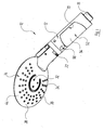
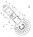
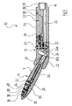
- FIG. 1 shows a sanitary hand shower 10, which comprises a handle 12 and a removable, releasably connected to the handle 12 shower head 14.
- connection nipple 16 is provided, to which a shower hose can be attached.
- the nipple 16 of the handle 12 surrounds an end portion of an in FIG. 5 to be recognized water inlet chamber 18, which merges in the direction of the connection nipple 16 away in a water-bearing channel 20. From this, water can be routed via a changeover device 22, which is not of further interest to the user, from the outside to one of three connection channels 24, which are each formed by a branch channel 24a and a channel 24b inclined thereto and of which FIG. 5 one can see it on average.
- Each of the three connecting channels 24 is in communication with one of three inner waterways 26, 28, 30 in the shower head 14, which in turn lead to functionally different, serving as water outlet openings nozzles 32, 34, 36.
- the nozzles 32, 34, 36 are provided in a known manner as a nozzle plate 38 side of a two-part housing 40 of the shower head 14.
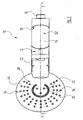
- the nozzles 32, 34, 36 form in the illustrated embodiment, three groups of nozzles, each on circles of different radius around the center of the approximately circular in plan view shower head 14 (see, eg FIG. 2 ) are arranged.
- On the circle with the smallest radius are three nozzles 32, which can produce relatively hard, usually a massage effect reaching water jets.
- These nozzles 32 are surrounded by an arcuate slot nozzle 34 which extends over approximately an arc of 270 °.
- This slit nozzle 34 can be a surge-like water jet remove.
- the slot nozzle 34 in turn is in an annular region which is close to the peripheral edge of the housing 40th of the shower head 14, surrounded by a plurality of nozzles 36 which lie on three concentric circles. From these nozzles 36 occurs during operation of the hand shower a variety of relatively soft, perceived as particularly pleasant effervescent jets.
- the two-part housing 40 of the shower head 14 comprises a trained as the aforementioned nozzle plate 38 shell 44 and an opposite shell 46, which are subsequently glued together tightly or welded.
- both shells 44, 46 are not visible here, the waterways 26, 28, 30 formed in the shower head 14, be it already in a molding injection process or only later by milling and / or drilling.
- composite housing 40 abutting sides of the shells 44, 46 of the shower head housing 40, these have on a circle which lies between the slit-shaped nozzle 34 and the nozzle group 36, each having a circular arc-shaped groove in the assembled shells 44, 46th a narrow, circular arc-shaped receiving space 48 result, which in section in FIG. 5 can be seen.
- This receiving space 48 extends like the slot nozzle 34 over an angle of about 270 ° and serves to receive a light-emitting diode arrangement.
- the latter comprises a plurality of light-emitting diodes 50, of those in FIG. 5 one is recognizable.
- the light-emitting diodes 50 preferably sit on a ribbon cable which has the same radius as the receiving space 48.
- the LEDs 50 are aligned so that they emit their light mainly radially outward, so that this radiates the radially outer edge region of the housing 40.
- the two shells 44, 46 are made of a transparent material, for which preferably polycarbonates (PC) or polymethyl methacrylate (PMMA) come into consideration.
- the light-emitting diode arrangement 50 is supplied with energy by a rechargeable accumulator which is not recognizable in the figures and which is accommodated in an accumulator unit 52.
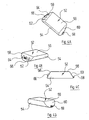
- the accumulator unit 52 has, as in particular in the FIGS. 4A to 4D can be seen, a shape in the manner of a half-cylinder with a curved outer surface 54, a flat support surface 56 and two opposite, relative to the flat support surface 56 inclined end faces 58 and 60.
- the two end faces 58 and 60 each form a kind chamfer of Semi-cylinder and extend from the outside in the direction of the support surface 56 at an angle to each other.
- two contacts 62, 64 are provided, one of which is connected to the positive pole and the other to the negative pole of the accumulator 52 housed in the accumulator.
- the contacts 62, 64 are flush with the end face 58 and lie on both sides of a protruding over the end face 58 locking sleeve 66.
- the longitudinal axis of the locking sleeve 66 extends parallel to the longitudinal axis of the accumulator 52nd
- a detent 68 is provided on the end face 58 opposite end face 60 of the accumulator 52.
- the contacts 62, 64 and the locking sleeve 66 are each arranged approximately centrally relative to the extension of the accumulator unit 52 perpendicular to its support surface 56, whereas the detent 68 is provided at a great distance from the support surface 56 and closely adjacent to the curved outer surface 54.
- the handle 12 has, in an end region adjacent to the connecting nipple 16, a material recess which corresponds to that region of the outer contour of the accumulator unit 52 which is formed by its bearing surface 56 and its end faces 58 and 60.
- This material recess forms a receptacle 70 with a bottom surface 72 whose dimensions correspond to those of the support surface 56 of the accumulator unit 52.
- In the longitudinal direction of the handle 12 go from the bottom surface 72 each in the direction of the outer surface of the handle 12 away from each other, from the bottom surface 72 inclined surfaces 74, 76 whose inclination angle relative to the bottom surface 72 to the inclination angle of the end faces 58, 60 of the accumulator 52 related on the support surface 56 is complementary.
- the inclined surface 76 of the receptacle 70 has a latching nose 68 of the accumulator 52 complementary recess 82.
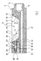
- the opposite inclined surface 74 in the handle 12 has a in, in Figures 5 and 6 to be recognized, radial cut triangular recess 84, so that the locking sleeve 66 of the accumulator unit 52 can be inserted radially into the recess 84 in a direction perpendicular to the longitudinal axis of the handle 12.
- This recess 84 opens a parallel to the longitudinal axis of the handle 12 extending guide channel 86 in which a retaining pin 88 is slidably mounted.
- the retaining pin 88 has a first end portion 90 with a cross section corresponding to that of the inner channel of the locking sleeve 66 of the accumulator unit 52.
- the cross section of the second end portion 92 of the retaining pin 88 opposite the first end portion 90 is greater than that of the first end portion 90 and in turn corresponds to the cross section of the guide channel 86.
- the transition region 94 between the first and second end portions 90,92 of the retaining pin 88 is conical ,
- the retaining pin 88 is acted on on the end face of the second end portion 92 with a coil spring 96 and is thus always pressed in the direction of the receptacle 84 and inserted accumulator unit 52 in the inner channel of its locking sleeve 66.
- the accumulator unit 52 inserted into the handle 12 is secured against being removed or dropped.
- a device for unlocking the accumulator unit 52 in the form of a push button 98 is provided.
- the push button 98 has a plunger 100, which is guided in a perpendicular to the guide channel 86 extending plunger channel 102 (see. FIG. 6 ).
- the plunger 100 has a circular cross-section and a free end on which a chamfer 104 is provided. This chamfer 104 has the same inclination as the conical region 94 of the retaining pin 88.
- the coil spring 96 is seated in a chamber 106 which is provided at the opposite end of the recess 84 of the guide channel 86 and extends coaxially thereto.
- the chamber 106 has a slightly larger diameter than the guide channel 86 and has a longitudinal extent which is less than the longitudinal extent of the coil spring 96 in the relaxed state. That is, the coil spring 96 abuts against a step formed at the junction between the chamber 106 and the guide channel 86, and is thereby prevented from being fully expanded.
- the plunger channel 102 is arranged such that when inserted into the channel 102 plunger 100 whose bevel 104 sits on the conical portion 94 of the retaining pin 88 when the retaining pin 88 is positioned in the guide channel 86, that the end face of its second end portion 92 with the the chamber 106 adjacent end of the guide channel 86 is flush, as in FIG. 6 is shown. It remains between the free end face of the plunger 100 and the outer circumferential surface of the first end portion 90 of the retaining pin 88 a distance.
- the plunger 100 is perpendicular to its end Longitudinal axis extending pressure plate 108 integrally formed.
- the plunger channel 102 widens to a recess 110 which surrounds and receives the pressure plate 108. The latter closes in its illustrated basic position flush with the outer surface of the handle 12.
- the accumulator unit 52 of the hand shower 10 is easily removed from the handle 12 or from the receptacle 70, since the receptacle 70 is directly accessible to the user from the outside.
- a removed accumulator unit 52 can then be supplied to an external charging station placed at an arbitrary location, through which the accumulator of the accumulator unit 52 can be charged.
- the contacts 62, 64 on the end face 58 of the accumulator 52 then serve as connections for connection to the charger.
- a second, identical accumulator unit 52 is provided, which can be inserted into the handle 12, while the first accumulator unit 52 is charged.
Landscapes
- Health & Medical Sciences (AREA)
- Engineering & Computer Science (AREA)
- Public Health (AREA)
- Life Sciences & Earth Sciences (AREA)
- Hydrology & Water Resources (AREA)
- Water Supply & Treatment (AREA)
- Epidemiology (AREA)
- General Engineering & Computer Science (AREA)
- Bathtubs, Showers, And Their Attachments (AREA)
Claims (10)
- Douchette sanitaire comprenant
une poignée (12) pouvant être raccordée à un flexible de ladite douchette;
un pommeau de douche (14), porté par ladite poignée (12) et offrant une pluralité d'orifices (32, 34, 36) de sortie d'eau ;
au moins un moyen d'éclairage (50) logé dans ledit pommeau de douche (14);
et
au moins un accumulateur par l'intermédiaire duquel ledit moyen d'éclairage (50) peut être alimenté en énergie, sachant que
ledit accumulateur est intégré dans une unité d'accumulation (52) retenue, de manière libérable, dans un dispositif de réception (70) auquel un utilisateur de ladite douchette (10) a accès depuis l'extérieur, caractérisée par le fait que l'unité d'accumulation présente des connexions (62, 64), en vue du raccordement à un appareil de mise en charge. - Douchette selon la revendication 1, caractérisée par le fait que le dispositif de réception (70) est prévu dans la poignée (12).
- Douchette selon la revendication 1 ou 2, caractérisée par le fait que le dispositif de réception (70) comprend un système de verrouillage (88, 96, 98) au moyen duquel l'unité d'accumulation (52) est retenue dans ledit dispositif de réception (70), de manière libérable.
- Douchette selon la revendication 3, caractérisée par le fait que le système de verrouillage (88, 96, 98) présente un moyen de retenue (88) qui pénètre dans l'unité d'accumulation (52), avec précontrainte, et est mobile entre une position de verrouillage prévenant une extraction ou une chute de ladite unité d'accumulation (52), et une position de libération dans laquelle ladite unité d'accumulation (52) peut être extraite du dispositif de réception (70).
- Douchette selon la revendication 4, caractérisée par le fait que le moyen de retenue (88) est réalisé sous la forme d'une broche de retenue (88), pénétrant dans une douille de retenue (66) prévue sur l'unité d'accumulation (52).
- Douchette selon la revendication 4 ou 5, caractérisée par le fait que la précontrainte du moyen de retenue (88) est exercée par un ressort (96).
- Douchette selon l'une des revendications 4 à 6, caractérisée par le fait qu'un moyen d'actionnement (98), manoeuvrable à la main, est prévu pour déplacer le moyen de retenue (88) vers sa position de libération.
- Douchette selon la revendication 7, caractérisée par le fait que le moyen d'actionnement (98) est réalisé sous la forme d'un bouton-poussoir (98) muni d'une surface de pression (104) par l'intermédiaire de laquelle une force peut être appliquée à une surface complémentaire (94) de la broche de retenue (88), suite à l'enfoncement dudit bouton-poussoir (98), de telle sorte que ladite broche de retenue (88) soit déplacée vers sa position de libération.
- Douchette selon la revendication 8, caractérisée par le fait que la direction de mouvement du bouton-poussoir (98) s'étend, pour l'essentiel, perpendiculairement à la direction de mouvement de la broche de retenue (88).
- Douchette selon l'une des revendications 1 à 9, caractérisée par le fait que le moyen d'éclairage (50) est une diode luminescente (50).
Applications Claiming Priority (2)
| Application Number | Priority Date | Filing Date | Title |
|---|---|---|---|
| DE102006021699A DE102006021699B3 (de) | 2006-05-10 | 2006-05-10 | Sanitäre Handbrause |
| PCT/EP2007/003928 WO2007128500A1 (fr) | 2006-05-10 | 2007-05-04 | Douchette sanitaire |
Publications (2)
| Publication Number | Publication Date |
|---|---|
| EP2016232A1 EP2016232A1 (fr) | 2009-01-21 |
| EP2016232B1 true EP2016232B1 (fr) | 2011-07-20 |
Family
ID=38434813
Family Applications (1)
| Application Number | Title | Priority Date | Filing Date |
|---|---|---|---|
| EP07724853A Not-in-force EP2016232B1 (fr) | 2006-05-10 | 2007-05-04 | Douchette sanitaire |
Country Status (4)
| Country | Link |
|---|---|
| EP (1) | EP2016232B1 (fr) |
| AT (1) | ATE517214T1 (fr) |
| DE (1) | DE102006021699B3 (fr) |
| WO (1) | WO2007128500A1 (fr) |
Families Citing this family (4)
| Publication number | Priority date | Publication date | Assignee | Title |
|---|---|---|---|---|
| WO2009027779A2 (fr) * | 2007-08-03 | 2009-03-05 | Industrias Ramon Soler, S.A. | Appareil sanitaire |
| DE502008002491D1 (de) | 2008-10-04 | 2011-03-10 | Kwc Ag | Umstellbarer Brausekopf |
| EP2301669A1 (fr) * | 2008-10-04 | 2011-03-30 | Kwc Ag | Pomme dotée d'un élément de maintien et d'une pomme de douche amovibles |
| US11602032B2 (en) | 2019-12-20 | 2023-03-07 | Kohler Co. | Systems and methods for lighted showering |
Family Cites Families (6)
| Publication number | Priority date | Publication date | Assignee | Title |
|---|---|---|---|---|
| JP2506350Y2 (ja) * | 1989-09-27 | 1996-08-07 | 株式会社マキタ | 充電器 |
| IL119431A (en) * | 1996-10-15 | 2000-10-31 | Joel Kehat | Colored light shower head |
| DE20017254U1 (de) * | 2000-08-31 | 2001-03-01 | Grigull, Berthold, 47809 Krefeld | Sanitär-Armatur |
| DE10128543A1 (de) * | 2001-06-13 | 2002-12-19 | Reglomat Ag Speicher | Wasserarmatur |
| EP1323872A1 (fr) * | 2001-12-28 | 2003-07-02 | Ewig Industries Co., LTD. | Module de commande multifonctionnelle de l'eau |
| DE102004028608A1 (de) * | 2004-06-04 | 2005-12-22 | Hansgrohe Ag | Handbrause |
-
2006
- 2006-05-10 DE DE102006021699A patent/DE102006021699B3/de not_active Expired - Fee Related
-
2007
- 2007-05-04 AT AT07724853T patent/ATE517214T1/de active
- 2007-05-04 EP EP07724853A patent/EP2016232B1/fr not_active Not-in-force
- 2007-05-04 WO PCT/EP2007/003928 patent/WO2007128500A1/fr not_active Ceased
Also Published As
| Publication number | Publication date |
|---|---|
| WO2007128500A1 (fr) | 2007-11-15 |
| DE102006021699B3 (de) | 2007-12-20 |
| EP2016232A1 (fr) | 2009-01-21 |
| ATE517214T1 (de) | 2011-08-15 |
Similar Documents
| Publication | Publication Date | Title |
|---|---|---|
| EP1778440B1 (fr) | Visseuse electrique sans fil | |
| DE69900518T2 (de) | Ausverriegelung für Schalter | |
| DE69818805T2 (de) | Injektionsvorrichtung für intra-okulare linsen | |
| DE60100221T2 (de) | Kupplungsmechanismus | |
| DE69209491T2 (de) | Mehrkanalstecker | |
| EP2684610A1 (fr) | Pomme de douche | |
| WO2007147711A1 (fr) | Point de séparation entre deux éléments partiels d'un système d'outil rotatif | |
| DE2136221A1 (de) | Arbeitsvorrichtung und Vorschub mechamsmus | |
| EP2016232B1 (fr) | Douchette sanitaire | |
| DE20308466U1 (de) | Innenraumleuchte | |
| DE10254609B4 (de) | Endoskopkopf | |
| DE10347945A1 (de) | Zusatzhandgriff | |
| DE212017000143U1 (de) | Adapter, Lichtquellenvorrichtung und Beleuchtungsvorrichtung | |
| EP2016231B1 (fr) | Système sanitaire comportant une douchette et une unité de charge | |
| DE3937570A1 (de) | Spannfutter | |
| EP1751356B1 (fr) | Douchette manuelle | |
| DE4420859A1 (de) | Hülsenhalter für ein optisches Verbindungsstück | |
| EP2344346B1 (fr) | Crayon lumineux | |
| EP1011159B1 (fr) | Connecteur combiné de charge et fluide | |
| DE68906297T2 (de) | Elektrodenhalter für das Lichtbogenschweissen mit schnellem Ausstoss der verbrauchten Elektrode. | |
| EP0945185B1 (fr) | Distributeur de fluide et son procédé de fabrication | |
| DE4309563C2 (de) | Netzkabelsteckanschluß | |
| DE3621901C2 (fr) | ||
| DE3018850A1 (de) | Druckbleistift mit minenfuehler | |
| EP3231615B1 (fr) | Imprimante à jet d'encre pour l'étiquette de marchandises comprenant un filtre et filtre d'une telle imprimante à jet d'encre |
Legal Events
| Date | Code | Title | Description |
|---|---|---|---|
| PUAI | Public reference made under article 153(3) epc to a published international application that has entered the european phase |
Free format text: ORIGINAL CODE: 0009012 |
|
| 17P | Request for examination filed |
Effective date: 20081107 |
|
| AK | Designated contracting states |
Kind code of ref document: A1 Designated state(s): AT BE BG CH CY CZ DE DK EE ES FI FR GB GR HU IE IS IT LI LT LU LV MC MT NL PL PT RO SE SI SK TR |
|
| AX | Request for extension of the european patent |
Extension state: AL BA HR MK RS |
|
| GRAP | Despatch of communication of intention to grant a patent |
Free format text: ORIGINAL CODE: EPIDOSNIGR1 |
|
| DAX | Request for extension of the european patent (deleted) | ||
| GRAJ | Information related to disapproval of communication of intention to grant by the applicant or resumption of examination proceedings by the epo deleted |
Free format text: ORIGINAL CODE: EPIDOSDIGR1 |
|
| GRAP | Despatch of communication of intention to grant a patent |
Free format text: ORIGINAL CODE: EPIDOSNIGR1 |
|
| GRAS | Grant fee paid |
Free format text: ORIGINAL CODE: EPIDOSNIGR3 |
|
| GRAA | (expected) grant |
Free format text: ORIGINAL CODE: 0009210 |
|
| AK | Designated contracting states |
Kind code of ref document: B1 Designated state(s): AT BE BG CH CY CZ DE DK EE ES FI FR GB GR HU IE IS IT LI LT LU LV MC MT NL PL PT RO SE SI SK TR |
|
| REG | Reference to a national code |
Ref country code: GB Ref legal event code: FG4D Free format text: NOT ENGLISH |
|
| REG | Reference to a national code |
Ref country code: CH Ref legal event code: EP |
|
| REG | Reference to a national code |
Ref country code: CH Ref legal event code: NV Representative=s name: FREI PATENTANWALTSBUERO AG |
|
| REG | Reference to a national code |
Ref country code: DE Ref legal event code: R096 Ref document number: 502007007725 Country of ref document: DE Effective date: 20110915 |
|
| REG | Reference to a national code |
Ref country code: NL Ref legal event code: VDEP Effective date: 20110720 |
|
| PG25 | Lapsed in a contracting state [announced via postgrant information from national office to epo] |
Ref country code: NL Free format text: LAPSE BECAUSE OF FAILURE TO SUBMIT A TRANSLATION OF THE DESCRIPTION OR TO PAY THE FEE WITHIN THE PRESCRIBED TIME-LIMIT Effective date: 20110720 Ref country code: FI Free format text: LAPSE BECAUSE OF FAILURE TO SUBMIT A TRANSLATION OF THE DESCRIPTION OR TO PAY THE FEE WITHIN THE PRESCRIBED TIME-LIMIT Effective date: 20110720 Ref country code: SE Free format text: LAPSE BECAUSE OF FAILURE TO SUBMIT A TRANSLATION OF THE DESCRIPTION OR TO PAY THE FEE WITHIN THE PRESCRIBED TIME-LIMIT Effective date: 20110720 Ref country code: LT Free format text: LAPSE BECAUSE OF FAILURE TO SUBMIT A TRANSLATION OF THE DESCRIPTION OR TO PAY THE FEE WITHIN THE PRESCRIBED TIME-LIMIT Effective date: 20110720 Ref country code: PT Free format text: LAPSE BECAUSE OF FAILURE TO SUBMIT A TRANSLATION OF THE DESCRIPTION OR TO PAY THE FEE WITHIN THE PRESCRIBED TIME-LIMIT Effective date: 20111121 Ref country code: IS Free format text: LAPSE BECAUSE OF FAILURE TO SUBMIT A TRANSLATION OF THE DESCRIPTION OR TO PAY THE FEE WITHIN THE PRESCRIBED TIME-LIMIT Effective date: 20111120 |
|
| REG | Reference to a national code |
Ref country code: IE Ref legal event code: FD4D |
|
| PG25 | Lapsed in a contracting state [announced via postgrant information from national office to epo] |
Ref country code: SI Free format text: LAPSE BECAUSE OF FAILURE TO SUBMIT A TRANSLATION OF THE DESCRIPTION OR TO PAY THE FEE WITHIN THE PRESCRIBED TIME-LIMIT Effective date: 20110720 Ref country code: GR Free format text: LAPSE BECAUSE OF FAILURE TO SUBMIT A TRANSLATION OF THE DESCRIPTION OR TO PAY THE FEE WITHIN THE PRESCRIBED TIME-LIMIT Effective date: 20111021 Ref country code: CY Free format text: LAPSE BECAUSE OF FAILURE TO SUBMIT A TRANSLATION OF THE DESCRIPTION OR TO PAY THE FEE WITHIN THE PRESCRIBED TIME-LIMIT Effective date: 20110720 Ref country code: LV Free format text: LAPSE BECAUSE OF FAILURE TO SUBMIT A TRANSLATION OF THE DESCRIPTION OR TO PAY THE FEE WITHIN THE PRESCRIBED TIME-LIMIT Effective date: 20110720 Ref country code: PL Free format text: LAPSE BECAUSE OF FAILURE TO SUBMIT A TRANSLATION OF THE DESCRIPTION OR TO PAY THE FEE WITHIN THE PRESCRIBED TIME-LIMIT Effective date: 20110720 |
|
| PG25 | Lapsed in a contracting state [announced via postgrant information from national office to epo] |
Ref country code: IE Free format text: LAPSE BECAUSE OF FAILURE TO SUBMIT A TRANSLATION OF THE DESCRIPTION OR TO PAY THE FEE WITHIN THE PRESCRIBED TIME-LIMIT Effective date: 20110720 Ref country code: CZ Free format text: LAPSE BECAUSE OF FAILURE TO SUBMIT A TRANSLATION OF THE DESCRIPTION OR TO PAY THE FEE WITHIN THE PRESCRIBED TIME-LIMIT Effective date: 20110720 Ref country code: SK Free format text: LAPSE BECAUSE OF FAILURE TO SUBMIT A TRANSLATION OF THE DESCRIPTION OR TO PAY THE FEE WITHIN THE PRESCRIBED TIME-LIMIT Effective date: 20110720 |
|
| PLBE | No opposition filed within time limit |
Free format text: ORIGINAL CODE: 0009261 |
|
| STAA | Information on the status of an ep patent application or granted ep patent |
Free format text: STATUS: NO OPPOSITION FILED WITHIN TIME LIMIT |
|
| PG25 | Lapsed in a contracting state [announced via postgrant information from national office to epo] |
Ref country code: RO Free format text: LAPSE BECAUSE OF FAILURE TO SUBMIT A TRANSLATION OF THE DESCRIPTION OR TO PAY THE FEE WITHIN THE PRESCRIBED TIME-LIMIT Effective date: 20110720 Ref country code: IT Free format text: LAPSE BECAUSE OF FAILURE TO SUBMIT A TRANSLATION OF THE DESCRIPTION OR TO PAY THE FEE WITHIN THE PRESCRIBED TIME-LIMIT Effective date: 20110720 Ref country code: EE Free format text: LAPSE BECAUSE OF FAILURE TO SUBMIT A TRANSLATION OF THE DESCRIPTION OR TO PAY THE FEE WITHIN THE PRESCRIBED TIME-LIMIT Effective date: 20110720 |
|
| 26N | No opposition filed |
Effective date: 20120423 |
|
| PG25 | Lapsed in a contracting state [announced via postgrant information from national office to epo] |
Ref country code: DK Free format text: LAPSE BECAUSE OF FAILURE TO SUBMIT A TRANSLATION OF THE DESCRIPTION OR TO PAY THE FEE WITHIN THE PRESCRIBED TIME-LIMIT Effective date: 20110720 |
|
| REG | Reference to a national code |
Ref country code: DE Ref legal event code: R097 Ref document number: 502007007725 Country of ref document: DE Effective date: 20120423 |
|
| BERE | Be: lapsed |
Owner name: HANSA METALLWERKE A.G. Effective date: 20120531 |
|
| PG25 | Lapsed in a contracting state [announced via postgrant information from national office to epo] |
Ref country code: MC Free format text: LAPSE BECAUSE OF NON-PAYMENT OF DUE FEES Effective date: 20120531 |
|
| REG | Reference to a national code |
Ref country code: CH Ref legal event code: PL |
|
| GBPC | Gb: european patent ceased through non-payment of renewal fee |
Effective date: 20120504 |
|
| PG25 | Lapsed in a contracting state [announced via postgrant information from national office to epo] |
Ref country code: LI Free format text: LAPSE BECAUSE OF NON-PAYMENT OF DUE FEES Effective date: 20120531 Ref country code: CH Free format text: LAPSE BECAUSE OF NON-PAYMENT OF DUE FEES Effective date: 20120531 |
|
| PG25 | Lapsed in a contracting state [announced via postgrant information from national office to epo] |
Ref country code: BE Free format text: LAPSE BECAUSE OF NON-PAYMENT OF DUE FEES Effective date: 20120531 |
|
| REG | Reference to a national code |
Ref country code: FR Ref legal event code: ST Effective date: 20130131 |
|
| REG | Reference to a national code |
Ref country code: DE Ref legal event code: R119 Ref document number: 502007007725 Country of ref document: DE Effective date: 20121201 |
|
| PG25 | Lapsed in a contracting state [announced via postgrant information from national office to epo] |
Ref country code: GB Free format text: LAPSE BECAUSE OF NON-PAYMENT OF DUE FEES Effective date: 20120504 Ref country code: ES Free format text: LAPSE BECAUSE OF FAILURE TO SUBMIT A TRANSLATION OF THE DESCRIPTION OR TO PAY THE FEE WITHIN THE PRESCRIBED TIME-LIMIT Effective date: 20111031 Ref country code: FR Free format text: LAPSE BECAUSE OF NON-PAYMENT OF DUE FEES Effective date: 20120531 |
|
| PG25 | Lapsed in a contracting state [announced via postgrant information from national office to epo] |
Ref country code: DE Free format text: LAPSE BECAUSE OF NON-PAYMENT OF DUE FEES Effective date: 20121201 Ref country code: BG Free format text: LAPSE BECAUSE OF FAILURE TO SUBMIT A TRANSLATION OF THE DESCRIPTION OR TO PAY THE FEE WITHIN THE PRESCRIBED TIME-LIMIT Effective date: 20111020 |
|
| REG | Reference to a national code |
Ref country code: AT Ref legal event code: MM01 Ref document number: 517214 Country of ref document: AT Kind code of ref document: T Effective date: 20120504 |
|
| PG25 | Lapsed in a contracting state [announced via postgrant information from national office to epo] |
Ref country code: MT Free format text: LAPSE BECAUSE OF FAILURE TO SUBMIT A TRANSLATION OF THE DESCRIPTION OR TO PAY THE FEE WITHIN THE PRESCRIBED TIME-LIMIT Effective date: 20110720 Ref country code: AT Free format text: LAPSE BECAUSE OF NON-PAYMENT OF DUE FEES Effective date: 20120504 |
|
| PG25 | Lapsed in a contracting state [announced via postgrant information from national office to epo] |
Ref country code: TR Free format text: LAPSE BECAUSE OF FAILURE TO SUBMIT A TRANSLATION OF THE DESCRIPTION OR TO PAY THE FEE WITHIN THE PRESCRIBED TIME-LIMIT Effective date: 20110720 |
|
| PG25 | Lapsed in a contracting state [announced via postgrant information from national office to epo] |
Ref country code: LU Free format text: LAPSE BECAUSE OF NON-PAYMENT OF DUE FEES Effective date: 20120504 |
|
| PG25 | Lapsed in a contracting state [announced via postgrant information from national office to epo] |
Ref country code: HU Free format text: LAPSE BECAUSE OF FAILURE TO SUBMIT A TRANSLATION OF THE DESCRIPTION OR TO PAY THE FEE WITHIN THE PRESCRIBED TIME-LIMIT Effective date: 20070504 |