EP2016232B1 - Hand-held sanitary shower - Google Patents
Hand-held sanitary shower Download PDFInfo
- Publication number
- EP2016232B1 EP2016232B1 EP07724853A EP07724853A EP2016232B1 EP 2016232 B1 EP2016232 B1 EP 2016232B1 EP 07724853 A EP07724853 A EP 07724853A EP 07724853 A EP07724853 A EP 07724853A EP 2016232 B1 EP2016232 B1 EP 2016232B1
- Authority
- EP
- European Patent Office
- Prior art keywords
- hand
- held
- handle
- accumulator
- sprinkler according
- Prior art date
- Legal status (The legal status is an assumption and is not a legal conclusion. Google has not performed a legal analysis and makes no representation as to the accuracy of the status listed.)
- Not-in-force
Links
- XLYOFNOQVPJJNP-UHFFFAOYSA-N water Substances O XLYOFNOQVPJJNP-UHFFFAOYSA-N 0.000 claims abstract description 10
- 230000000881 depressing effect Effects 0.000 claims 1
- 230000000295 complement effect Effects 0.000 description 4
- 210000002445 nipple Anatomy 0.000 description 4
- 230000002349 favourable effect Effects 0.000 description 2
- 239000000463 material Substances 0.000 description 2
- 229920003229 poly(methyl methacrylate) Polymers 0.000 description 2
- 239000004417 polycarbonate Substances 0.000 description 2
- 229920000515 polycarbonate Polymers 0.000 description 2
- 239000004926 polymethyl methacrylate Substances 0.000 description 2
- 238000004891 communication Methods 0.000 description 1
- 239000002131 composite material Substances 0.000 description 1
- 230000001419 dependent effect Effects 0.000 description 1
- 238000011161 development Methods 0.000 description 1
- 230000018109 developmental process Effects 0.000 description 1
- 238000005553 drilling Methods 0.000 description 1
- 230000000694 effects Effects 0.000 description 1
- 230000005611 electricity Effects 0.000 description 1
- 238000002347 injection Methods 0.000 description 1
- 239000007924 injection Substances 0.000 description 1
- 238000000034 method Methods 0.000 description 1
- 238000003801 milling Methods 0.000 description 1
- 238000000465 moulding Methods 0.000 description 1
- 230000002093 peripheral effect Effects 0.000 description 1
- 230000007704 transition Effects 0.000 description 1
- 239000012780 transparent material Substances 0.000 description 1
Images
Classifications
-
- E—FIXED CONSTRUCTIONS
- E03—WATER SUPPLY; SEWERAGE
- E03C—DOMESTIC PLUMBING INSTALLATIONS FOR FRESH WATER OR WASTE WATER; SINKS
- E03C1/00—Domestic plumbing installations for fresh water or waste water; Sinks
- E03C1/02—Plumbing installations for fresh water
- E03C1/04—Water-basin installations specially adapted to wash-basins or baths
- E03C1/0408—Water installations especially for showers
- E03C1/0409—Shower handles
-
- F—MECHANICAL ENGINEERING; LIGHTING; HEATING; WEAPONS; BLASTING
- F21—LIGHTING
- F21V—FUNCTIONAL FEATURES OR DETAILS OF LIGHTING DEVICES OR SYSTEMS THEREOF; STRUCTURAL COMBINATIONS OF LIGHTING DEVICES WITH OTHER ARTICLES, NOT OTHERWISE PROVIDED FOR
- F21V33/00—Structural combinations of lighting devices with other articles, not otherwise provided for
- F21V33/0004—Personal or domestic articles
- F21V33/004—Sanitary equipment, e.g. mirrors, showers, toilet seats or paper dispensers
-
- F—MECHANICAL ENGINEERING; LIGHTING; HEATING; WEAPONS; BLASTING
- F21—LIGHTING
- F21L—LIGHTING DEVICES OR SYSTEMS THEREOF, BEING PORTABLE OR SPECIALLY ADAPTED FOR TRANSPORTATION
- F21L4/00—Electric lighting devices with self-contained electric batteries or cells
- F21L4/08—Electric lighting devices with self-contained electric batteries or cells characterised by means for in situ recharging of the batteries or cells
-
- F—MECHANICAL ENGINEERING; LIGHTING; HEATING; WEAPONS; BLASTING
- F21—LIGHTING
- F21S—NON-PORTABLE LIGHTING DEVICES; SYSTEMS THEREOF; VEHICLE LIGHTING DEVICES SPECIALLY ADAPTED FOR VEHICLE EXTERIORS
- F21S9/00—Lighting devices with a built-in power supply; Systems employing lighting devices with a built-in power supply
- F21S9/02—Lighting devices with a built-in power supply; Systems employing lighting devices with a built-in power supply the power supply being a battery or accumulator
-
- F—MECHANICAL ENGINEERING; LIGHTING; HEATING; WEAPONS; BLASTING
- F21—LIGHTING
- F21Y—INDEXING SCHEME ASSOCIATED WITH SUBCLASSES F21K, F21L, F21S and F21V, RELATING TO THE FORM OR THE KIND OF THE LIGHT SOURCES OR OF THE COLOUR OF THE LIGHT EMITTED
- F21Y2115/00—Light-generating elements of semiconductor light sources
- F21Y2115/10—Light-emitting diodes [LED]
Definitions
- the invention relates to a sanitary hand shower according to the preamble of claim 1.
- WO 2005118967 discloses a sanitary hand shower with a) a connectable to a shower hose handle; b) a handle supported by the shower head, which comprises a plurality of water outlet openings; c) at least one lamp arranged in the shower head; and d) at least one accumulator, by means of which the luminous means can be supplied with energy.
- Under accumulator is basically any rechargeable battery to understand, which may optionally be housed in a separate housing.
- To charge the battery is in the WO 2005/118967 A1 the hand shower is inserted into a charging station mounted in the area of use of the hand shower, which usually forms at the same time the normal holder for the hand shower.
- the accumulator is arranged inaccessible to the user from the outside in the interior of the hand shower and can not be removed from the hand shower, without the hand shower would have to be at least partially disassembled.
- the accumulator can therefore be charged by the user only by this brings the hand shower in the charging station, which, however, is located in the wet area of the bathroom.
- US 2003 0125842 describes a hand shower that has a multifunction water control module. The module is powered by batteries.
- the object of the invention is to provide a hand shower of the type mentioned, which takes into account these problems.
- the accumulator unit with the accumulator can be easily removed by the user from the sanitary hand shower and an external charging station, which need not be located in the wet area of the bathroom, are supplied.
- an external charging station which need not be located in the wet area of the bathroom.
- a handle with conventional dimensions provides enough space to provide a receiving device in which a battery unit is releasably held.
- the receiving device comprises a locking device with which the accumulator unit is releasably held in the receiving device. It is particularly advantageous if the locking device comprises a movable between a locking position in which the accumulator is secured against being removed or falling out, and a release position in which the accumulator can be removed from the receiving device, movable holding means which under bias in the Accumulator unit engages. Due to the bias of the holding means prevents the accumulator accidentally falls out of the hand shower.
- a technically simple holding device is present when the holding means is designed as a holding pin, which engages in a recess provided on the accumulator unit holding bushing.
- a retaining bush has a hollow cylinder as an inner channel, in which a retaining pin can intervene well with complementary cross-section. As a result, a Verrriegelung is achieved perpendicular to the longitudinal axis of the retaining sleeve.
- a bias of the holding means is achieved in a simple manner, if a spring is used for this purpose.
- a manually operable actuating means is provided for the user.
- no further tools are required for releasing the accumulator unit from the hand-held shower, so that the accumulator unit can be removed from the hand-held shower quickly and easily if required.
- a both technically favorable as well as a user-perceived as pleasant type of actuation enabling configuration is achieved when the actuating means is designed as a push button, which has a pressure surface over which by pressing the push button on a counter surface of the retaining pin a force is exercised, so that the retaining pin is moved to its release position.
- the direction of movement of the push button extends substantially perpendicular to the direction of movement of the retaining pin.
- the push button can be mounted in the outer circumferential surface of the handle and moved radially to the longitudinal axis, whereas the locking of the accumulator unit can then take place in the longitudinal direction of the handle.
- Light-emitting diodes are characterized on the one hand by their small size and on the other hand by their low energy requirement.
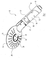
- FIG. 1 shows a sanitary hand shower 10, which comprises a handle 12 and a removable, releasably connected to the handle 12 shower head 14.
- connection nipple 16 is provided, to which a shower hose can be attached.
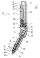
- the nipple 16 of the handle 12 surrounds an end portion of an in FIG. 5 to be recognized water inlet chamber 18, which merges in the direction of the connection nipple 16 away in a water-bearing channel 20. From this, water can be routed via a changeover device 22, which is not of further interest to the user, from the outside to one of three connection channels 24, which are each formed by a branch channel 24a and a channel 24b inclined thereto and of which FIG. 5 one can see it on average.
- Each of the three connecting channels 24 is in communication with one of three inner waterways 26, 28, 30 in the shower head 14, which in turn lead to functionally different, serving as water outlet openings nozzles 32, 34, 36.
- the nozzles 32, 34, 36 are provided in a known manner as a nozzle plate 38 side of a two-part housing 40 of the shower head 14.
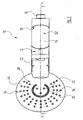
- the nozzles 32, 34, 36 form in the illustrated embodiment, three groups of nozzles, each on circles of different radius around the center of the approximately circular in plan view shower head 14 (see, eg FIG. 2 ) are arranged.
- On the circle with the smallest radius are three nozzles 32, which can produce relatively hard, usually a massage effect reaching water jets.
- These nozzles 32 are surrounded by an arcuate slot nozzle 34 which extends over approximately an arc of 270 °.
- This slit nozzle 34 can be a surge-like water jet remove.
- the slot nozzle 34 in turn is in an annular region which is close to the peripheral edge of the housing 40th of the shower head 14, surrounded by a plurality of nozzles 36 which lie on three concentric circles. From these nozzles 36 occurs during operation of the hand shower a variety of relatively soft, perceived as particularly pleasant effervescent jets.
- the two-part housing 40 of the shower head 14 comprises a trained as the aforementioned nozzle plate 38 shell 44 and an opposite shell 46, which are subsequently glued together tightly or welded.
- both shells 44, 46 are not visible here, the waterways 26, 28, 30 formed in the shower head 14, be it already in a molding injection process or only later by milling and / or drilling.
- composite housing 40 abutting sides of the shells 44, 46 of the shower head housing 40, these have on a circle which lies between the slit-shaped nozzle 34 and the nozzle group 36, each having a circular arc-shaped groove in the assembled shells 44, 46th a narrow, circular arc-shaped receiving space 48 result, which in section in FIG. 5 can be seen.
- This receiving space 48 extends like the slot nozzle 34 over an angle of about 270 ° and serves to receive a light-emitting diode arrangement.
- the latter comprises a plurality of light-emitting diodes 50, of those in FIG. 5 one is recognizable.
- the light-emitting diodes 50 preferably sit on a ribbon cable which has the same radius as the receiving space 48.
- the LEDs 50 are aligned so that they emit their light mainly radially outward, so that this radiates the radially outer edge region of the housing 40.
- the two shells 44, 46 are made of a transparent material, for which preferably polycarbonates (PC) or polymethyl methacrylate (PMMA) come into consideration.
- the light-emitting diode arrangement 50 is supplied with energy by a rechargeable accumulator which is not recognizable in the figures and which is accommodated in an accumulator unit 52.
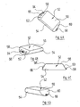
- the accumulator unit 52 has, as in particular in the FIGS. 4A to 4D can be seen, a shape in the manner of a half-cylinder with a curved outer surface 54, a flat support surface 56 and two opposite, relative to the flat support surface 56 inclined end faces 58 and 60.
- the two end faces 58 and 60 each form a kind chamfer of Semi-cylinder and extend from the outside in the direction of the support surface 56 at an angle to each other.
- two contacts 62, 64 are provided, one of which is connected to the positive pole and the other to the negative pole of the accumulator 52 housed in the accumulator.
- the contacts 62, 64 are flush with the end face 58 and lie on both sides of a protruding over the end face 58 locking sleeve 66.
- the longitudinal axis of the locking sleeve 66 extends parallel to the longitudinal axis of the accumulator 52nd
- a detent 68 is provided on the end face 58 opposite end face 60 of the accumulator 52.
- the contacts 62, 64 and the locking sleeve 66 are each arranged approximately centrally relative to the extension of the accumulator unit 52 perpendicular to its support surface 56, whereas the detent 68 is provided at a great distance from the support surface 56 and closely adjacent to the curved outer surface 54.
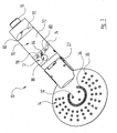
- the handle 12 has, in an end region adjacent to the connecting nipple 16, a material recess which corresponds to that region of the outer contour of the accumulator unit 52 which is formed by its bearing surface 56 and its end faces 58 and 60.
- This material recess forms a receptacle 70 with a bottom surface 72 whose dimensions correspond to those of the support surface 56 of the accumulator unit 52.
- In the longitudinal direction of the handle 12 go from the bottom surface 72 each in the direction of the outer surface of the handle 12 away from each other, from the bottom surface 72 inclined surfaces 74, 76 whose inclination angle relative to the bottom surface 72 to the inclination angle of the end faces 58, 60 of the accumulator 52 related on the support surface 56 is complementary.
- the inclined surface 76 of the receptacle 70 has a latching nose 68 of the accumulator 52 complementary recess 82.
- the opposite inclined surface 74 in the handle 12 has a in, in Figures 5 and 6 to be recognized, radial cut triangular recess 84, so that the locking sleeve 66 of the accumulator unit 52 can be inserted radially into the recess 84 in a direction perpendicular to the longitudinal axis of the handle 12.
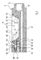
- This recess 84 opens a parallel to the longitudinal axis of the handle 12 extending guide channel 86 in which a retaining pin 88 is slidably mounted.
- the retaining pin 88 has a first end portion 90 with a cross section corresponding to that of the inner channel of the locking sleeve 66 of the accumulator unit 52.
- the cross section of the second end portion 92 of the retaining pin 88 opposite the first end portion 90 is greater than that of the first end portion 90 and in turn corresponds to the cross section of the guide channel 86.
- the transition region 94 between the first and second end portions 90,92 of the retaining pin 88 is conical ,
- the retaining pin 88 is acted on on the end face of the second end portion 92 with a coil spring 96 and is thus always pressed in the direction of the receptacle 84 and inserted accumulator unit 52 in the inner channel of its locking sleeve 66.
- the accumulator unit 52 inserted into the handle 12 is secured against being removed or dropped.
- a device for unlocking the accumulator unit 52 in the form of a push button 98 is provided.
- the push button 98 has a plunger 100, which is guided in a perpendicular to the guide channel 86 extending plunger channel 102 (see. FIG. 6 ).
- the plunger 100 has a circular cross-section and a free end on which a chamfer 104 is provided. This chamfer 104 has the same inclination as the conical region 94 of the retaining pin 88.
- the coil spring 96 is seated in a chamber 106 which is provided at the opposite end of the recess 84 of the guide channel 86 and extends coaxially thereto.
- the chamber 106 has a slightly larger diameter than the guide channel 86 and has a longitudinal extent which is less than the longitudinal extent of the coil spring 96 in the relaxed state. That is, the coil spring 96 abuts against a step formed at the junction between the chamber 106 and the guide channel 86, and is thereby prevented from being fully expanded.
- the plunger channel 102 is arranged such that when inserted into the channel 102 plunger 100 whose bevel 104 sits on the conical portion 94 of the retaining pin 88 when the retaining pin 88 is positioned in the guide channel 86, that the end face of its second end portion 92 with the the chamber 106 adjacent end of the guide channel 86 is flush, as in FIG. 6 is shown. It remains between the free end face of the plunger 100 and the outer circumferential surface of the first end portion 90 of the retaining pin 88 a distance.
- the plunger 100 is perpendicular to its end Longitudinal axis extending pressure plate 108 integrally formed.
- the plunger channel 102 widens to a recess 110 which surrounds and receives the pressure plate 108. The latter closes in its illustrated basic position flush with the outer surface of the handle 12.
- the accumulator unit 52 of the hand shower 10 is easily removed from the handle 12 or from the receptacle 70, since the receptacle 70 is directly accessible to the user from the outside.
- a removed accumulator unit 52 can then be supplied to an external charging station placed at an arbitrary location, through which the accumulator of the accumulator unit 52 can be charged.
- the contacts 62, 64 on the end face 58 of the accumulator 52 then serve as connections for connection to the charger.
- a second, identical accumulator unit 52 is provided, which can be inserted into the handle 12, while the first accumulator unit 52 is charged.
Landscapes
- Health & Medical Sciences (AREA)
- Engineering & Computer Science (AREA)
- Public Health (AREA)
- Life Sciences & Earth Sciences (AREA)
- Hydrology & Water Resources (AREA)
- Water Supply & Treatment (AREA)
- Epidemiology (AREA)
- General Engineering & Computer Science (AREA)
- Bathtubs, Showers, And Their Attachments (AREA)
Abstract
Description
Die Erfindung betrifft eine sanitäre Handbrause gemäß dem Oberbegiff des Anspruchs 1.The invention relates to a sanitary hand shower according to the preamble of claim 1.
Eine derartige sanitäre Handbrause ist in der
Der Akkumulator kann also vom Benutzer nur aufgeladen werden, indem dieser die Handbrause in die Ladestation bringt, welche sich jedoch im Naßbereich des Badezimmers befindet. Der Gedanke, daß im Naßbereich seines Badezimmers Strom, nämlich der Ladestrom zum Aufladen des Akkumulators, fließt, ist manchem Benutzer unangenehm und wird als Gefahrenquelle empfunden.
Bei der Handbrause der
Aufgabe der Erfindung ist es, eine Handbrause der eingangs genannten Art zu schaffen, welche diesen Problemen Rechnung trägt.The object of the invention is to provide a hand shower of the type mentioned, which takes into account these problems.
Diese Aufgabe wird bei einer sanitären Handbrause der eingangs genannten Art dadurch gelöst, daß die Akkumulatoreinheit Anschlüsse zur Verbindung mit einem Ladegerät aufweist.This object is achieved in a sanitary hand shower of the type mentioned in that the accumulator unit has connections for connection to a charger.
Dadurch kann die Akkumulatoreinheit mit dem Akkumulator einfach von dem Benutzer aus der sanitären Handbrause herausgenommen und einer externen Ladestation, die sich nicht im Naßbereich des Badezimmers befinden muß, zugeführt werden. Darüber hinaus besteht die Möglichkeit, eine entleerte Akkumulatoreinheit einfach gegen eine aufgeladene Akkumulatoreinheit auszutauschen, so daß die Handbrause stets vollständig betriebsbereit ist, auch während die entleerte Akkumulatoreinheit aufgeladen wird.Thus, the accumulator unit with the accumulator can be easily removed by the user from the sanitary hand shower and an external charging station, which need not be located in the wet area of the bathroom, are supplied. In addition, there is the possibility of a simply emptied accumulator unit to replace a charged accumulator unit, so that the hand shower is always fully operational, even while the empty accumulator unit is charged.
Vorteilhafte Weiterbildungen sind in den abhängigen Ansprüchen angegeben.Advantageous developments are specified in the dependent claims.
Es ist insbesondere praktisch, wenn die Aufnahmeeinrichtung im Handgriff vorgesehen ist. Ein Handgriff mit üblichen Abmessungen bietet genügend Raum, um eine Aufnahmeeinrichtung vorzusehen, in der eine Akkumulatoreinheit lösbar gehalten ist.It is particularly useful when the receiving device is provided in the handle. A handle with conventional dimensions provides enough space to provide a receiving device in which a battery unit is releasably held.
Um eine sichere Befestigung der Akkumulatoreinheit an der Handbrause zu gewährleisten, ist es vorteilhaft, wenn die Aufnahmeeinrichtung eine Verriegelungseinrichtung umfaßt, mit der die Akkumulatoreinheit lösbar in der Aufnahmeeinrichtung gehalten ist. Dabei ist es insbesondere günstig, wenn die Verriegelungseinrichtung ein zwischen einer Verriegelungsstellung, in welcher die Akkumulatoreinheit vor einem Herausnehmen oder Herausfallen gesichert ist, und einer Freigabestellung, in welcher die Akkumulatoreinheit aus der Aufnahmeeinrichtung herausgenommen werden kann, bewegbares Haltemittel umfaßt, welches unter Vorspannung in die Akkumulatoreinheit eingreift. Aufgrund der Vorspannung des Haltemittels ist verhindert, daß die Akkumulatoreinheit versehentlich aus der Handbrause herausfällt.In order to ensure a secure attachment of the accumulator unit to the hand shower, it is advantageous if the receiving device comprises a locking device with which the accumulator unit is releasably held in the receiving device. It is particularly advantageous if the locking device comprises a movable between a locking position in which the accumulator is secured against being removed or falling out, and a release position in which the accumulator can be removed from the receiving device, movable holding means which under bias in the Accumulator unit engages. Due to the bias of the holding means prevents the accumulator accidentally falls out of the hand shower.
Eine technisch einfache Haltevorrichtung liegt vor, wenn das Haltemittel als Haltestift ausgebildet ist, welcher in eine an der Akkumulatoreinheit vorgesehene Haltebuchse eingreift. Eine Haltebuchse weist als Hohlzylinder einen inneren Kanal auf, in welchen ein Haltestift mit dazu komplementärem Querschnitt gut eingreifen kann. Dadurch wird eine Verrriegelung senkrecht zur Längsachse der Haltebuchse erzielt.A technically simple holding device is present when the holding means is designed as a holding pin, which engages in a recess provided on the accumulator unit holding bushing. A retaining bush has a hollow cylinder as an inner channel, in which a retaining pin can intervene well with complementary cross-section. As a result, a Verrriegelung is achieved perpendicular to the longitudinal axis of the retaining sleeve.
Eine Vorspannung des Haltemittels wird auf einfache Weise erreicht, wenn dazu eine Feder eingesetzt wird.A bias of the holding means is achieved in a simple manner, if a spring is used for this purpose.
Für den Benutzer ist es insbesondere angenehm, wenn zum Bewegen des Haltemittels in seine Freigabestellung ein von Hand betätigbares Betätigungsmittel vorgesehen ist. Anders ausgedrückt ist zum Lösen der Akkumulatoreinheit von der Handbrause kein weiteres Werkzeug nötig, so daß die Akkumulatoreinheit bei Bedarf schnell und unkompliziert aus der Handbrause herausgenommen werden kann. Eine sowohl technisch günstige als auch eine vom Benutzer als angenehm empfundene Betätigungsart ermöglichende Ausgestaltung wird erzielt, wenn das Betätigungsmittel als Druckknopf ausgebildet ist, welcher eine Druckfläche aufweist, über die durch das Eindrücken des Druckknopfes auf eine Gegenfläche des Haltestiftes eine Kraft ausübbar ist, so daß der Haltestift in seine Freigabestellung bewegt wird.For the user, it is particularly pleasant if, for moving the holding means into its release position, a manually operable actuating means is provided. In other words, no further tools are required for releasing the accumulator unit from the hand-held shower, so that the accumulator unit can be removed from the hand-held shower quickly and easily if required. A both technically favorable as well as a user-perceived as pleasant type of actuation enabling configuration is achieved when the actuating means is designed as a push button, which has a pressure surface over which by pressing the push button on a counter surface of the retaining pin a force is exercised, so that the retaining pin is moved to its release position.
Im Hinblick auf die meist längliche Ausgestaltung eines Handgriffs einer Handbrause ist es günstig, wenn die Bewegungsrichtung des Druckknopfs im wesentlichen senkrecht zur Bewegungsrichtung des Haltestifts verläuft. Beispielsweise kann der Druckknopf in der Außenmantelfläche des Haltegriffs angebracht und radial zu dessen Längsachse bewegt werden, wogegen die Verriegelung der Akkumulatoreinheit dann in Längsrichtung des Handgriffes erfolgen kann.With regard to the usually elongated configuration of a handle of a hand shower, it is advantageous if the direction of movement of the push button extends substantially perpendicular to the direction of movement of the retaining pin. For example, the push button can be mounted in the outer circumferential surface of the handle and moved radially to the longitudinal axis, whereas the locking of the accumulator unit can then take place in the longitudinal direction of the handle.
Was das Leuchtmittel im Duschkopf betrifft, ist es aus technischer Sicht günstig, wenn dieses durch wenigstens eine Leuchtdiode gebildet ist. Leuchtdioden zeichnen sich zum einen durch ihre geringe Größe und zum anderen durch ihren geringen Energiebedarf aus.As far as the bulb in the shower head, it is favorable from a technical point of view, if this by at least a light-emitting diode is formed. Light-emitting diodes are characterized on the one hand by their small size and on the other hand by their low energy requirement.
Ein Ausführungsbeispiel der Erfindung wird nachfolgend anhand der Zeichnung näher erläutert; in dieser zeigen:
- Figur 1
- eine isometrische Darstellung einer sanitären Handbrause mit einer auswechselbaren Akkumula- toreinheit;
- Figur 2
- eine isometrische Darstellung der Handbrause von
Figur 1 aus einer anderen Blickrichtung; - Figur 3
- eine isometrische Darstellung der Handbrause von
Figur 1 aus einer dritten Blickrichtung, wobei die auswechselbare Akkumulatoreinheit herausgenommen ist; - Figuren 4A bis 4D
- isometrische Darstellungen der auswechselbaren Akkumulatoreinheit von
Figur 1 aus verschie- denen Blickrichtungen; - Figur 5
- einen Schnitt durch die Handbrause von
Figur 2 entlang der dortigen Schnittlinie V-V; und - Figur 6
- einen in größerem Maßstab dargestellten Axial- schnitt eines Abschnitts des Handgriffs der Handbrause von
Figur 2 .
- FIG. 1
- an isometric view of a sanitary hand shower with a replaceable accumulator unit;
- FIG. 2
- an isometric illustration of the hand shower of
FIG. 1 from another perspective; - FIG. 3
- an isometric illustration of the hand shower of
FIG. 1 from a third viewing direction, the interchangeable accumulator unit being taken out; - FIGS. 4A to 4D
- Isometric representations of the replaceable accumulator unit of
FIG. 1 from different perspectives; - FIG. 5
- a section through the hand shower of
FIG. 2 along the local section line VV; and - FIG. 6
- a larger scale shown axial section of a portion of the handle of the hand shower of
FIG. 2 ,
An dem dem Duschkopf 14 gegenüberliegenden Ende des Handgriffs 12 ist ein Anschlußnippel 16 vorgesehen, an welchem ein Brauseschlauch befestigt werden kann. Der Anschlußnippel 16 des Handgriffs 12 umgibt einen Endbereich einer in
Die Düsen 32, 34, 36 sind in einer in bekannter Weise als Düsenplatte 38 ausgebildeten Seite eines zweiteiligen Gehäuses 40 des Duschkopfes 14 vorgesehen. Die Düsen 32, 34, 36 bilden beim dargestellten Ausführungsbeispiel drei Gruppen von Düsen, die jeweils auf Kreisen mit unterschiedlichem Radius um den Mittelpunkt des in der Draufsicht etwa kreisförmigen Duschkopfs 14 (vgl. z.B.
Zur Verbindung der inneren Wasserwege 26, 28, 30 im Duschkopf 14 mit den Verbindungskanälen 24 im Handgriff 12 münden die Wasserwege 26, 28, 30 jeweils in außenliegenden Verbindungsstutzen, von denen in
Das zweiteilig ausgebildete Gehäuse 40 des Duschkopfs 14 umfaßt eine als die bereits erwähnte Düsenplatte 38 ausgebildete Schale 44 sowie eine gegenüberliegende Schale 46, welche nachträglich miteinander dicht verklebt oder verschweißt sind. In beiden Schalen 44, 46 sind, hier nicht zu erkennen, die Wasserwege 26, 28, 30 im Duschkopf 14 ausgeformt, sei dies bereits bei einem formgebenden Spritzprozess oder erst nachträglich durch Fräsen und/ oder Bohren. Auf den bei zusammengesetztem Gehäuse 40 aneinander anliegenden Seiten der Schalen 44, 46 des Duschkopf-Gehäuses 40 weisen diese auf einem Kreis, der zwischen der schlitzförmigen Düse 34 und der Düsengruppe 36 liegt, jeweils eine kreisbogenförmige Nut auf, die bei zusammengesetzten Schalen 44, 46 einen schmalen, kreisbogenförmigen Aufnahmeraum 48 ergeben, welcher im Schnitt in
Die Leuchtdioden 50 sind dabei so ausgerichtet, daß sie ihr Licht hauptsächlich radial nach außen abstrahlen, so daß dieses den radial außenliegenden Randbereich des Gehäuses 40 durchstrahlt. Dazu sind die beiden Schalen 44, 46 aus einem transparenten Material gefertigt, wofür vorzugsweise Polycarbonate (PC) oder Polymethylmethacrylat (PMMA) in Betracht kommen.The
Die Leuchtdiodenanordnung 50 wird von einem in den Figuren nicht zu erkennenden wiederaufladbaren Akkumulator, der in einer Akkumulatoreinheit 52 untergebracht ist, mit Energie versorgt. Die Akkumulatoreinheit 52 hat, wie insbesondere in den
Auf der der Stirnfläche 58 gegenüberliegenden Stirnfläche 60 der Akkumulatoreinheit 52 ist eine Rastnase 68 vorgesehen. Die Kontakte 62, 64 und die Verriegelungsbuchse 66 sind bezogen auf die Erstreckung der Akkumulatoreinheit 52 senkrecht zu ihrer Auflagefläche 56 jeweils in etwa mittig angeordnet, wogegen die Rastnase 68 in großem Abstand zur Auflagefläche 56 und dicht benachbart zur gewölbten Außenfläche 54 vorgesehen ist.On the
Der Handgriff 12 weist in einem dem Anschlußnippel 16 benachbarten Endbereich eine Materialausnehmung auf, welche demjenigen Bereich der äußeren Kontur der Akkumulatoreinheit 52 entspricht, der durch ihre Auflagefläche 56 und ihre Stirnflächen 58 und 60 gebildet ist. Diese Materialausnehmung bildet eine Aufnahme 70 mit einer Bodenfläche 72, deren Abmessungen denjenigen der Auflagefläche 56 der Akkumulatoreinheit 52 entsprechen. In Längsrichtung des Handgriffes 12 gehen von der Bodenfläche 72 jeweils in Richtung auf die Außenfläche des Handgriffes 12 voneinander weg verlaufende, zur Bodenfläche 72 geneigte Flächen 74, 76 ab, deren Neigungswinkel zur Bodenfläche 72 zu dem Neigungswinkel der Stirnflächen 58, 60 der Akkumulatoreinheit 52 bezogen auf deren Auflagefläche 56 komplementär ist.The
In der geneigten Fläche 74 der Aufnahme 70 sind zu den Kontakten 62, 64 der Akkumulatoreinheit 52 passende Kontake 78, 80 vorgesehen (vgl.
Zur Arretierung der Akkumulatoreiriheit 52 im Handgriff 12 weist die geneigte Fläche 76 der Aufnahme 70 eine zur Rastnase 68 der Akkumulatoreinheit 52 komplementäre Ausnehmung 82 auf. Für den gleichen Zweck weist die gegenüberliegende geneigte Fläche 74 im Handgriff 12 eine im, in
In diese Ausnehmung 84 mündet ein parallel zur Längsachse des Handgriffs 12 verlaufender Führungskanal 86, in welchem ein Haltestift 88 verschiebbar gelagert ist. Der Haltestift 88 weist einen ersten Endbereich 90 mit einem Querschnitt auf, welcher demjenigen des inneren Kanals der Verriegelungsbuchse 66 der Akkumulatoreinheit 52 entspricht. Der Querschnitt des dem ersten Endbereich 90 gegenüberliegenden zweiten Endbereichs 92 des Haltestiftes 88 ist größer als derjenige des ersten Endbereichs 90 und entspricht seinerseits dem Querschnitt des Führungskanals 86. Der Übergangsbereich 94 zwischen dem ersten und dem zweiten Endbereichs 90,92 des Haltestiftes 88 ist konisch ausgebildet. Der Haltestift 88 ist auf der Stirnseite des zweiten Endbereichs 92 mit einer Schraubenfeder 96 beaufschlagt und wird so stets in Richtung auf die Aufnahme 84 und bei eingesetzter Akkumulatoreinheit 52 in den Innenkanal ihrer Verriegelungsbuchse 66 hineingedrückt. Dadurch ist die in den Handgriff 12 eingesetzte Akkumulatoreinheit 52 vor einem Herausnehmen oder -fallen gesichert.In this
Um nun die Akkumulatoreinheit 52 aus der Aufnahme 70 im Handgriff 12 herausnehmen zu können, ist eine Einrichtung zum Entriegeln der Akkumulatoreinheit 52 in Form eines Druckknopfes 98 vorgesehen. Der Druckknopf 98 weist einen Stößel 100 auf, der in einem senkrecht zum Führungskanal 86 verlaufenden Stößelkanal 102 geführt ist (vgl.
Die Schraubenfeder 96 sitzt in einer Kammer 106, welche am der Ausnehmung 84 gegenüberliegenden Ende des Führungskanals 86 vorgesehen ist und koaxial dazu verläuft. Die Kammer 106 weist einen etwas größeren Durchmesser auf als der Führungskanal 86 und hat eine Längserstreckung, die geringer ist als die Längserstreckung der Schraubenfeder 96 in entspanntem Zustand. D.h., die Schraubenfeder 96 stößt gegen eine am Übergang zwischen der Kammer 106 und dem Führungskanal 86 gebildete Stufe an und ist dadurch an einer vollständigen Entspannung gehindert.The
Der Stößelkanal 102 ist derart angeordnet, daß bei in den Kanal 102 eingesetztem Stößel 100 dessen Fase 104 auf dem konischen Bereich 94 des Haltestiftes 88 sitzt, wenn der Haltestift 88 so in dem Führungskanal 86 positioniert ist, daß die Stirnseite seines zweiten Endbereichs 92 mit dem der Kammer 106 benachbarten Ende des Führungskanals 86 bündig abschließt, wie es in
An seinem dem Ende mit der Fase 104 gegenüberliegenden Ende ist der Stößel 100 an eine senkrecht zu seiner Längsachse verlaufende Druckplatte 108 angeformt. In Richtung auf die Außenmantelfläche des Handgriffs 12 erweitert sich der Stößelkanal 102 zu einer Ausnehmung 110, welche die Druckplatte 108 umgibt und aufnimmt. Letztere schließt in ihrer dargestellten Grundstellung bündig mit der Außenfläche des Handgriffs 12 ab.At its end opposite the
Wird nun der Druckknopf 98 von außen betätigt und die Druckplatte 108 mit dem Stößel 100 bezogen auf die Achse des Handgriffs 12 radial nach innen gedrückt, so wird der Haltestift 88 durch die aufeinander liegenden schrägen Flächen der Fase 104 des Stößels 100 und des konischen Bereichs 94 des Haltestiftes 88 in
Wird der Druckknopf 98 losgelassen, so wird der Haltestift 88 durch die Schraubenfeder 96 wieder so weit zurückgeschoben, bis die Stirnfläche des zweiten Endbereichs des Haltestiftes 88 mit dem Ende des Führungskanals 86 auf Seiten der Kammer 104 fluchtet und der erste Endbereich 90 des Haltestifts 88 teilweise in die Ausnehmung 84 im Handgriff 12 ragt, wie es in
Soll eine andere, gegebenenfalls neu aufgeladene Akkumulatoreinheit 52 in den Handgriff 12 der Handbrause 10 eingesetzt werden, so muß dazu ebenfalls der Druckknopf 98 betätigt werden, um den Haltestift 88 in Richtung auf die Kammer 106 zu verfahren. Ansonsten wäre ein Einbringen der Verriegelungsbuchse 66 der Akkumülatoreinheit 52 in die Ausnehmung 84 der Akkumulatoreinheit-Aufnahme 70 unmöglich, da die Akkumulatoreinheit 52 dann mit der Außenmantelfläche ihrer Verriegelungsbuchse 66 auf den in die Ausnehmung 84 des Handgriffs 12 ragenden Endbereich 90 des Haltestifts 88 zu liegen käme.If another, optionally recharged
Wie aus dem oben Gesagten hervorgeht, ist die Akkumulatoreinheit 52 der Handbrause 10 auf einfache Weise aus dem Handgriff 12 bzw. aus dessen Aufnahme 70 herauszunehmen, da die Aufnahme 70 von außen für den Benutzer direkt zugänglich ist. Eine herausgenommene Akkumulatoreinheit 52 kann dann einer externen, an einem beliebigen Ort plazierten Ladestation zugeführt werden, durch welche der Akkumulator der Akkumulatoreinheit 52 aufgeladen werden kann. Die Kontakte 62, 64 an der Stirnfläche 58 der Akkumulatoreinheit 52 dienen dann als Anschlüsse zur Verbindung mit dem Ladegerät.As can be seen from the above, the
Gegebenenfalls ist eine zweite, baugleiche Akkumulatoreinheit 52 vorhanden, die in den Handgriff 12 eingesetzt werden kann, während die erste Akkumulatoreinheit 52 aufgeladen wird.Optionally, a second,
Claims (10)
- Sanitary hand-held sprinkler having:a handle (12) which can be connected to a sprinkler hose;a shower head (14) which is carried by the handle (12) and comprises a plurality of water outlet apertures (32, 34, 36);at least one illuminant (50) arranged in the shower head (14);
andat least one battery (52) by which the illuminant (50) can be supplied with power; whereinthe battery (52) is accommodated in a battery unit (52) which is held in a releasable manner in a receiving device (70) which is accessible to a user of the hand-held sprinkler (10) from outside;
characterised in thatthe battery unit has connections (62, 64) for connection to a charger. - Hand-held sprinkler according to claim 1, characterised in that the receiving device (70) is provided in the handle (12).
- Hand-held sprinkler according to claim 1 or 2, characterised in that the receiving device (70) comprises an interlocking device (88, 96, 98) by means of which the battery unit (52) is held in the receiving device (70) in a releasable manner.
- Hand-held sprinkler according to claim 3, characterised in that the interlocking device (88, 96, 98) comprises a retaining means (88) which can be moved between an interlocking position, in which the battery unit (52) is secured against being taken out or dropping out, and a releasing position, in which the battery unit (52) can be taken out of the receiving device (70), which retaining means (88) engages in the battery unit (52) under pretensioning.
- Hand-held sprinkler according to claim 4, characterised in that the retaining means (88) is constructed as a retaining pin (88) which engages in a retaining bush (66) provided on the battery unit (52).
- Hand-held sprinkler according to claim 4 or 5, characterised in that the pretensioning of the retaining means (88) is brought about by a spring (96).
- Hand-held sprinkler according to one of claims 4 to 6, characterised in that a manually actuatable actuating means (98) is provided for moving the retaining means (88) into its releasing position.
- Hand-held sprinkler according to claim 7, characterised in that the actuating means (98) is constructed as a push-button (98) which has a pressure surface (104) via which a force can be exerted on a counter-surface (94) of the retaining pin (88) by depressing the push-button (98), so that said retaining pin (88) is moved into its releasing position.
- Hand-held sprinkler according to claim 8, characterised in that the direction of movement of the push-button (98) extends substantially perpendicularly to the direction of movement of the retaining pin (88).
- Hand-held sprinkler according to one of claims 1 to 9, characterised in that the illuminant (50) is a light-emitting diode (50).
Applications Claiming Priority (2)
| Application Number | Priority Date | Filing Date | Title |
|---|---|---|---|
| DE102006021699A DE102006021699B3 (en) | 2006-05-10 | 2006-05-10 | Sanitary hand shower |
| PCT/EP2007/003928 WO2007128500A1 (en) | 2006-05-10 | 2007-05-04 | Hand-held sanitary shower |
Publications (2)
| Publication Number | Publication Date |
|---|---|
| EP2016232A1 EP2016232A1 (en) | 2009-01-21 |
| EP2016232B1 true EP2016232B1 (en) | 2011-07-20 |
Family
ID=38434813
Family Applications (1)
| Application Number | Title | Priority Date | Filing Date |
|---|---|---|---|
| EP07724853A Not-in-force EP2016232B1 (en) | 2006-05-10 | 2007-05-04 | Hand-held sanitary shower |
Country Status (4)
| Country | Link |
|---|---|
| EP (1) | EP2016232B1 (en) |
| AT (1) | ATE517214T1 (en) |
| DE (1) | DE102006021699B3 (en) |
| WO (1) | WO2007128500A1 (en) |
Families Citing this family (4)
| Publication number | Priority date | Publication date | Assignee | Title |
|---|---|---|---|---|
| WO2009027779A2 (en) * | 2007-08-03 | 2009-03-05 | Industrias Ramon Soler, S.A. | Sanitary apparatus |
| EP2301669A1 (en) * | 2008-10-04 | 2011-03-30 | Kwc Ag | Sprinkler with separable holding section and sprinkler head |
| DE502008002491D1 (en) | 2008-10-04 | 2011-03-10 | Kwc Ag | Reversible shower head |
| US11602032B2 (en) | 2019-12-20 | 2023-03-07 | Kohler Co. | Systems and methods for lighted showering |
Family Cites Families (6)
| Publication number | Priority date | Publication date | Assignee | Title |
|---|---|---|---|---|
| JP2506350Y2 (en) * | 1989-09-27 | 1996-08-07 | 株式会社マキタ | Charger |
| IL119431A (en) * | 1996-10-15 | 2000-10-31 | Joel Kehat | Colored light shower head |
| DE20017254U1 (en) * | 2000-08-31 | 2001-03-01 | Grigull, Berthold, 47809 Krefeld | Sanitary fitting |
| DE10128543A1 (en) * | 2001-06-13 | 2002-12-19 | Reglomat Ag Speicher | water fitting |
| EP1323872A1 (en) * | 2001-12-28 | 2003-07-02 | Ewig Industries Co., LTD. | "Multi-functional water control module" |
| DE102004028608A1 (en) * | 2004-06-04 | 2005-12-22 | Hansgrohe Ag | Handheld shower |
-
2006
- 2006-05-10 DE DE102006021699A patent/DE102006021699B3/en not_active Expired - Fee Related
-
2007
- 2007-05-04 EP EP07724853A patent/EP2016232B1/en not_active Not-in-force
- 2007-05-04 WO PCT/EP2007/003928 patent/WO2007128500A1/en not_active Ceased
- 2007-05-04 AT AT07724853T patent/ATE517214T1/en active
Also Published As
| Publication number | Publication date |
|---|---|
| WO2007128500A1 (en) | 2007-11-15 |
| DE102006021699B3 (en) | 2007-12-20 |
| EP2016232A1 (en) | 2009-01-21 |
| ATE517214T1 (en) | 2011-08-15 |
Similar Documents
| Publication | Publication Date | Title |
|---|---|---|
| EP1778440B1 (en) | Battery-driven screwdriver | |
| DE69900518T2 (en) | Lockout for switches | |
| DE69818805T2 (en) | INJECTION DEVICE FOR INTRA-OCULAR LENSES | |
| DE60100221T2 (en) | clutch mechanism | |
| DE3610329C2 (en) | ||
| DE69209491T2 (en) | MULTI-CHANNEL PLUG | |
| EP2684610A1 (en) | Shower head | |
| DE3500085A1 (en) | DENTAL HANDPIECE | |
| WO2007147711A1 (en) | Junction between two components of a rotating tool system | |
| DE2136221A1 (en) | Working device and feed mechamsmus | |
| DE20308466U1 (en) | Interior light | |
| DE10347945A1 (en) | Additional handle | |
| DE212017000143U1 (en) | Adapter, light source device and lighting device | |
| EP2016231B1 (en) | Sanitary system comprising a hand-held shower and a charging set | |
| EP2016232A1 (en) | Hand-held sanitary shower | |
| DE3937570A1 (en) | CHUCK | |
| EP1751356B1 (en) | Hand-held shower | |
| DE4420859A1 (en) | Sleeve holder for an optical connector | |
| EP2344346A1 (en) | Fluorescent pencil | |
| DE68906297T2 (en) | Electrode holder for arc welding with quick ejection of the used electrode. | |
| EP1278478A1 (en) | Carving device | |
| EP0945185B1 (en) | Fluid dispensing device and its manufacturing method | |
| DE29820933U1 (en) | Combined charging and fluid connector | |
| DE4309563C2 (en) | Power cord connector | |
| DE3621901C2 (en) |
Legal Events
| Date | Code | Title | Description |
|---|---|---|---|
| PUAI | Public reference made under article 153(3) epc to a published international application that has entered the european phase |
Free format text: ORIGINAL CODE: 0009012 |
|
| 17P | Request for examination filed |
Effective date: 20081107 |
|
| AK | Designated contracting states |
Kind code of ref document: A1 Designated state(s): AT BE BG CH CY CZ DE DK EE ES FI FR GB GR HU IE IS IT LI LT LU LV MC MT NL PL PT RO SE SI SK TR |
|
| AX | Request for extension of the european patent |
Extension state: AL BA HR MK RS |
|
| GRAP | Despatch of communication of intention to grant a patent |
Free format text: ORIGINAL CODE: EPIDOSNIGR1 |
|
| DAX | Request for extension of the european patent (deleted) | ||
| GRAJ | Information related to disapproval of communication of intention to grant by the applicant or resumption of examination proceedings by the epo deleted |
Free format text: ORIGINAL CODE: EPIDOSDIGR1 |
|
| GRAP | Despatch of communication of intention to grant a patent |
Free format text: ORIGINAL CODE: EPIDOSNIGR1 |
|
| GRAS | Grant fee paid |
Free format text: ORIGINAL CODE: EPIDOSNIGR3 |
|
| GRAA | (expected) grant |
Free format text: ORIGINAL CODE: 0009210 |
|
| AK | Designated contracting states |
Kind code of ref document: B1 Designated state(s): AT BE BG CH CY CZ DE DK EE ES FI FR GB GR HU IE IS IT LI LT LU LV MC MT NL PL PT RO SE SI SK TR |
|
| REG | Reference to a national code |
Ref country code: GB Ref legal event code: FG4D Free format text: NOT ENGLISH |
|
| REG | Reference to a national code |
Ref country code: CH Ref legal event code: EP |
|
| REG | Reference to a national code |
Ref country code: CH Ref legal event code: NV Representative=s name: FREI PATENTANWALTSBUERO AG |
|
| REG | Reference to a national code |
Ref country code: DE Ref legal event code: R096 Ref document number: 502007007725 Country of ref document: DE Effective date: 20110915 |
|
| REG | Reference to a national code |
Ref country code: NL Ref legal event code: VDEP Effective date: 20110720 |
|
| PG25 | Lapsed in a contracting state [announced via postgrant information from national office to epo] |
Ref country code: NL Free format text: LAPSE BECAUSE OF FAILURE TO SUBMIT A TRANSLATION OF THE DESCRIPTION OR TO PAY THE FEE WITHIN THE PRESCRIBED TIME-LIMIT Effective date: 20110720 Ref country code: FI Free format text: LAPSE BECAUSE OF FAILURE TO SUBMIT A TRANSLATION OF THE DESCRIPTION OR TO PAY THE FEE WITHIN THE PRESCRIBED TIME-LIMIT Effective date: 20110720 Ref country code: SE Free format text: LAPSE BECAUSE OF FAILURE TO SUBMIT A TRANSLATION OF THE DESCRIPTION OR TO PAY THE FEE WITHIN THE PRESCRIBED TIME-LIMIT Effective date: 20110720 Ref country code: LT Free format text: LAPSE BECAUSE OF FAILURE TO SUBMIT A TRANSLATION OF THE DESCRIPTION OR TO PAY THE FEE WITHIN THE PRESCRIBED TIME-LIMIT Effective date: 20110720 Ref country code: PT Free format text: LAPSE BECAUSE OF FAILURE TO SUBMIT A TRANSLATION OF THE DESCRIPTION OR TO PAY THE FEE WITHIN THE PRESCRIBED TIME-LIMIT Effective date: 20111121 Ref country code: IS Free format text: LAPSE BECAUSE OF FAILURE TO SUBMIT A TRANSLATION OF THE DESCRIPTION OR TO PAY THE FEE WITHIN THE PRESCRIBED TIME-LIMIT Effective date: 20111120 |
|
| REG | Reference to a national code |
Ref country code: IE Ref legal event code: FD4D |
|
| PG25 | Lapsed in a contracting state [announced via postgrant information from national office to epo] |
Ref country code: SI Free format text: LAPSE BECAUSE OF FAILURE TO SUBMIT A TRANSLATION OF THE DESCRIPTION OR TO PAY THE FEE WITHIN THE PRESCRIBED TIME-LIMIT Effective date: 20110720 Ref country code: GR Free format text: LAPSE BECAUSE OF FAILURE TO SUBMIT A TRANSLATION OF THE DESCRIPTION OR TO PAY THE FEE WITHIN THE PRESCRIBED TIME-LIMIT Effective date: 20111021 Ref country code: CY Free format text: LAPSE BECAUSE OF FAILURE TO SUBMIT A TRANSLATION OF THE DESCRIPTION OR TO PAY THE FEE WITHIN THE PRESCRIBED TIME-LIMIT Effective date: 20110720 Ref country code: LV Free format text: LAPSE BECAUSE OF FAILURE TO SUBMIT A TRANSLATION OF THE DESCRIPTION OR TO PAY THE FEE WITHIN THE PRESCRIBED TIME-LIMIT Effective date: 20110720 Ref country code: PL Free format text: LAPSE BECAUSE OF FAILURE TO SUBMIT A TRANSLATION OF THE DESCRIPTION OR TO PAY THE FEE WITHIN THE PRESCRIBED TIME-LIMIT Effective date: 20110720 |
|
| PG25 | Lapsed in a contracting state [announced via postgrant information from national office to epo] |
Ref country code: IE Free format text: LAPSE BECAUSE OF FAILURE TO SUBMIT A TRANSLATION OF THE DESCRIPTION OR TO PAY THE FEE WITHIN THE PRESCRIBED TIME-LIMIT Effective date: 20110720 Ref country code: CZ Free format text: LAPSE BECAUSE OF FAILURE TO SUBMIT A TRANSLATION OF THE DESCRIPTION OR TO PAY THE FEE WITHIN THE PRESCRIBED TIME-LIMIT Effective date: 20110720 Ref country code: SK Free format text: LAPSE BECAUSE OF FAILURE TO SUBMIT A TRANSLATION OF THE DESCRIPTION OR TO PAY THE FEE WITHIN THE PRESCRIBED TIME-LIMIT Effective date: 20110720 |
|
| PLBE | No opposition filed within time limit |
Free format text: ORIGINAL CODE: 0009261 |
|
| STAA | Information on the status of an ep patent application or granted ep patent |
Free format text: STATUS: NO OPPOSITION FILED WITHIN TIME LIMIT |
|
| PG25 | Lapsed in a contracting state [announced via postgrant information from national office to epo] |
Ref country code: RO Free format text: LAPSE BECAUSE OF FAILURE TO SUBMIT A TRANSLATION OF THE DESCRIPTION OR TO PAY THE FEE WITHIN THE PRESCRIBED TIME-LIMIT Effective date: 20110720 Ref country code: IT Free format text: LAPSE BECAUSE OF FAILURE TO SUBMIT A TRANSLATION OF THE DESCRIPTION OR TO PAY THE FEE WITHIN THE PRESCRIBED TIME-LIMIT Effective date: 20110720 Ref country code: EE Free format text: LAPSE BECAUSE OF FAILURE TO SUBMIT A TRANSLATION OF THE DESCRIPTION OR TO PAY THE FEE WITHIN THE PRESCRIBED TIME-LIMIT Effective date: 20110720 |
|
| 26N | No opposition filed |
Effective date: 20120423 |
|
| PG25 | Lapsed in a contracting state [announced via postgrant information from national office to epo] |
Ref country code: DK Free format text: LAPSE BECAUSE OF FAILURE TO SUBMIT A TRANSLATION OF THE DESCRIPTION OR TO PAY THE FEE WITHIN THE PRESCRIBED TIME-LIMIT Effective date: 20110720 |
|
| REG | Reference to a national code |
Ref country code: DE Ref legal event code: R097 Ref document number: 502007007725 Country of ref document: DE Effective date: 20120423 |
|
| BERE | Be: lapsed |
Owner name: HANSA METALLWERKE A.G. Effective date: 20120531 |
|
| PG25 | Lapsed in a contracting state [announced via postgrant information from national office to epo] |
Ref country code: MC Free format text: LAPSE BECAUSE OF NON-PAYMENT OF DUE FEES Effective date: 20120531 |
|
| REG | Reference to a national code |
Ref country code: CH Ref legal event code: PL |
|
| GBPC | Gb: european patent ceased through non-payment of renewal fee |
Effective date: 20120504 |
|
| PG25 | Lapsed in a contracting state [announced via postgrant information from national office to epo] |
Ref country code: LI Free format text: LAPSE BECAUSE OF NON-PAYMENT OF DUE FEES Effective date: 20120531 Ref country code: CH Free format text: LAPSE BECAUSE OF NON-PAYMENT OF DUE FEES Effective date: 20120531 |
|
| PG25 | Lapsed in a contracting state [announced via postgrant information from national office to epo] |
Ref country code: BE Free format text: LAPSE BECAUSE OF NON-PAYMENT OF DUE FEES Effective date: 20120531 |
|
| REG | Reference to a national code |
Ref country code: FR Ref legal event code: ST Effective date: 20130131 |
|
| REG | Reference to a national code |
Ref country code: DE Ref legal event code: R119 Ref document number: 502007007725 Country of ref document: DE Effective date: 20121201 |
|
| PG25 | Lapsed in a contracting state [announced via postgrant information from national office to epo] |
Ref country code: GB Free format text: LAPSE BECAUSE OF NON-PAYMENT OF DUE FEES Effective date: 20120504 Ref country code: ES Free format text: LAPSE BECAUSE OF FAILURE TO SUBMIT A TRANSLATION OF THE DESCRIPTION OR TO PAY THE FEE WITHIN THE PRESCRIBED TIME-LIMIT Effective date: 20111031 Ref country code: FR Free format text: LAPSE BECAUSE OF NON-PAYMENT OF DUE FEES Effective date: 20120531 |
|
| PG25 | Lapsed in a contracting state [announced via postgrant information from national office to epo] |
Ref country code: DE Free format text: LAPSE BECAUSE OF NON-PAYMENT OF DUE FEES Effective date: 20121201 Ref country code: BG Free format text: LAPSE BECAUSE OF FAILURE TO SUBMIT A TRANSLATION OF THE DESCRIPTION OR TO PAY THE FEE WITHIN THE PRESCRIBED TIME-LIMIT Effective date: 20111020 |
|
| REG | Reference to a national code |
Ref country code: AT Ref legal event code: MM01 Ref document number: 517214 Country of ref document: AT Kind code of ref document: T Effective date: 20120504 |
|
| PG25 | Lapsed in a contracting state [announced via postgrant information from national office to epo] |
Ref country code: MT Free format text: LAPSE BECAUSE OF FAILURE TO SUBMIT A TRANSLATION OF THE DESCRIPTION OR TO PAY THE FEE WITHIN THE PRESCRIBED TIME-LIMIT Effective date: 20110720 Ref country code: AT Free format text: LAPSE BECAUSE OF NON-PAYMENT OF DUE FEES Effective date: 20120504 |
|
| PG25 | Lapsed in a contracting state [announced via postgrant information from national office to epo] |
Ref country code: TR Free format text: LAPSE BECAUSE OF FAILURE TO SUBMIT A TRANSLATION OF THE DESCRIPTION OR TO PAY THE FEE WITHIN THE PRESCRIBED TIME-LIMIT Effective date: 20110720 |
|
| PG25 | Lapsed in a contracting state [announced via postgrant information from national office to epo] |
Ref country code: LU Free format text: LAPSE BECAUSE OF NON-PAYMENT OF DUE FEES Effective date: 20120504 |
|
| PG25 | Lapsed in a contracting state [announced via postgrant information from national office to epo] |
Ref country code: HU Free format text: LAPSE BECAUSE OF FAILURE TO SUBMIT A TRANSLATION OF THE DESCRIPTION OR TO PAY THE FEE WITHIN THE PRESCRIBED TIME-LIMIT Effective date: 20070504 |