EP2015144B1 - Bilderzeugungsvorrichtung mit Verriegelungsmitteln für Einheiten - Google Patents
Bilderzeugungsvorrichtung mit Verriegelungsmitteln für Einheiten Download PDFInfo
- Publication number
- EP2015144B1 EP2015144B1 EP08158937A EP08158937A EP2015144B1 EP 2015144 B1 EP2015144 B1 EP 2015144B1 EP 08158937 A EP08158937 A EP 08158937A EP 08158937 A EP08158937 A EP 08158937A EP 2015144 B1 EP2015144 B1 EP 2015144B1
- Authority
- EP
- European Patent Office
- Prior art keywords
- forming apparatus
- image forming
- main body
- door
- opening
- Prior art date
- Legal status (The legal status is an assumption and is not a legal conclusion. Google has not performed a legal analysis and makes no representation as to the accuracy of the status listed.)
- Ceased
Links
Images


Classifications
-
- G—PHYSICS
- G03—PHOTOGRAPHY; CINEMATOGRAPHY; ANALOGOUS TECHNIQUES USING WAVES OTHER THAN OPTICAL WAVES; ELECTROGRAPHY; HOLOGRAPHY
- G03G—ELECTROGRAPHY; ELECTROPHOTOGRAPHY; MAGNETOGRAPHY
- G03G15/00—Apparatus for electrographic processes using a charge pattern
-
- G—PHYSICS
- G03—PHOTOGRAPHY; CINEMATOGRAPHY; ANALOGOUS TECHNIQUES USING WAVES OTHER THAN OPTICAL WAVES; ELECTROGRAPHY; HOLOGRAPHY
- G03G—ELECTROGRAPHY; ELECTROPHOTOGRAPHY; MAGNETOGRAPHY
- G03G21/00—Arrangements not provided for by groups G03G13/00 - G03G19/00, e.g. cleaning, elimination of residual charge
- G03G21/16—Mechanical means for facilitating the maintenance of the apparatus, e.g. modular arrangements
- G03G21/1604—Arrangement or disposition of the entire apparatus
- G03G21/1623—Means to access the interior of the apparatus
- G03G21/1633—Means to access the interior of the apparatus using doors or covers
-
- G—PHYSICS
- G03—PHOTOGRAPHY; CINEMATOGRAPHY; ANALOGOUS TECHNIQUES USING WAVES OTHER THAN OPTICAL WAVES; ELECTROGRAPHY; HOLOGRAPHY
- G03G—ELECTROGRAPHY; ELECTROPHOTOGRAPHY; MAGNETOGRAPHY
- G03G21/00—Arrangements not provided for by groups G03G13/00 - G03G19/00, e.g. cleaning, elimination of residual charge
- G03G21/16—Mechanical means for facilitating the maintenance of the apparatus, e.g. modular arrangements
- G03G21/1642—Mechanical means for facilitating the maintenance of the apparatus, e.g. modular arrangements for connecting the different parts of the apparatus
- G03G21/1647—Mechanical connection means
-
- G—PHYSICS
- G03—PHOTOGRAPHY; CINEMATOGRAPHY; ANALOGOUS TECHNIQUES USING WAVES OTHER THAN OPTICAL WAVES; ELECTROGRAPHY; HOLOGRAPHY
- G03G—ELECTROGRAPHY; ELECTROPHOTOGRAPHY; MAGNETOGRAPHY
- G03G2221/00—Processes not provided for by group G03G2215/00, e.g. cleaning or residual charge elimination
- G03G2221/16—Mechanical means for facilitating the maintenance of the apparatus, e.g. modular arrangements and complete machine concepts
- G03G2221/1606—Mechanical means for facilitating the maintenance of the apparatus, e.g. modular arrangements and complete machine concepts for the photosensitive element
- G03G2221/1609—Mechanical means for facilitating the maintenance of the apparatus, e.g. modular arrangements and complete machine concepts for the photosensitive element protective arrangements for preventing damage
-
- G—PHYSICS
- G03—PHOTOGRAPHY; CINEMATOGRAPHY; ANALOGOUS TECHNIQUES USING WAVES OTHER THAN OPTICAL WAVES; ELECTROGRAPHY; HOLOGRAPHY
- G03G—ELECTROGRAPHY; ELECTROPHOTOGRAPHY; MAGNETOGRAPHY
- G03G2221/00—Processes not provided for by group G03G2215/00, e.g. cleaning or residual charge elimination
- G03G2221/16—Mechanical means for facilitating the maintenance of the apparatus, e.g. modular arrangements and complete machine concepts
- G03G2221/1651—Mechanical means for facilitating the maintenance of the apparatus, e.g. modular arrangements and complete machine concepts for connecting the different parts
- G03G2221/1654—Locks and means for positioning or alignment
-
- G—PHYSICS
- G03—PHOTOGRAPHY; CINEMATOGRAPHY; ANALOGOUS TECHNIQUES USING WAVES OTHER THAN OPTICAL WAVES; ELECTROGRAPHY; HOLOGRAPHY
- G03G—ELECTROGRAPHY; ELECTROPHOTOGRAPHY; MAGNETOGRAPHY
- G03G2221/00—Processes not provided for by group G03G2215/00, e.g. cleaning or residual charge elimination
- G03G2221/16—Mechanical means for facilitating the maintenance of the apparatus, e.g. modular arrangements and complete machine concepts
- G03G2221/1678—Frame structures
- G03G2221/169—Structural door designs
-
- G—PHYSICS
- G03—PHOTOGRAPHY; CINEMATOGRAPHY; ANALOGOUS TECHNIQUES USING WAVES OTHER THAN OPTICAL WAVES; ELECTROGRAPHY; HOLOGRAPHY
- G03G—ELECTROGRAPHY; ELECTROPHOTOGRAPHY; MAGNETOGRAPHY
- G03G2221/00—Processes not provided for by group G03G2215/00, e.g. cleaning or residual charge elimination
- G03G2221/16—Mechanical means for facilitating the maintenance of the apparatus, e.g. modular arrangements and complete machine concepts
- G03G2221/18—Cartridge systems
- G03G2221/1815—Cartridge systems for cleaning or developing but not being a process cartridge
Definitions
- the present invention relates to an image forming apparatus, and, more particularly, to an image forming apparatus having a detachable photosensitive cartridge.
- An image forming apparatus is an apparatus which prints an image on, e.g., a sheet of paper serving as the printing medium based on image signals.
- a laser beam is irradiated on a photosensitive drum charged with a predetermined potential to form an electrostatic latent image on an outer peripheral surface thereof.
- the electrostatic latent image is developed into a visible image with developer. Then, the visible image is transferred and fixed on the paper, thereby printing the image.
- a conventional image forming apparatus includes a main body defining the external appearance, a developing unit which develops an image on the paper, and the like.
- the developing unit may include one or more of an exposure unit having, e.g., a laser diode to generate a laser beam, a photosensitive cartridge having a photosensitive drum on which an electrostatic latent image is formed by the laser beam irradiated by the exposure unit, a charge roller which charges the photosensitive drum, a developing cartridge which develops the electrostatic latent image into a visible image using a developer, a transfer unit which transfers the visible image formed on the photosensitive drum on the paper, and a fixing unit which fixes the visible image on the paper by heating and pressing the visible image transferred on the paper.
- an exposure unit having, e.g., a laser diode to generate a laser beam
- a photosensitive cartridge having a photosensitive drum on which an electrostatic latent image is formed by the laser beam irradiated by the exposure unit
- a charge roller which charges the photo
- Consumables such as the photosensitive cartridge may be detachably installed in the main body, allowing them to be replaced, e.g., when they are exhausted.
- the image forming apparatus with detachably installed consumable(s) is transported or shipped via a vehicle or the like, due to the vibration and/or shock imparted the image forming apparatus during the transport, the consumables may move from their original positions in the main body, and may become damaged.
- padding material may be placed into the main body to prevent the movement of the consumables within the image forming apparatus body during packaging for shipment. Once the image forming apparatus reaches its intended location of operation, the padding material is removed. Although not intended to be a part of the image forming apparatus in operation, such padding material is nevertheless manufactured and/or purchased for use as packing material In addition, the padding material needs to be removed from the main body and disposed of before use. Consequently, it presents inconvenience to the user, and results in waste of material.
- US 2006/0177237 discloses a locking system for a door of an image forming apparatus.
- the present invention has been made in order to solve the above problems. It is an aspect of the invention to provide an image forming apparatus capable reducing the risk of detachably installed consumables, e.g., a photosensitive cartridge, being damaged during the transporting or shipping of the image forming apparatus.
- consumables e.g., a photosensitive cartridge
- an image forming apparatus comprising: a main body having a first opening; a consumable which is detachably installed in the main body; a door which is rotatably installed on the main body to open and close the first opening; and a locking member operable in association with the door to secure the consumable in place when the door is closed.
- Slide bars may be installed on the main body to be movable in first and second directions as the door is opened and closed, respectively, and the locking members may be rotatably installed on the slide bars to secure/release the consumable as the slide bars move.
- Ends of the slide bars further from the first opening may be elastically biased toward the first opening by elastic members, and the opposite ends of the slide bars may be supported by the pressing bars movably installed on the door.
- Each of the locking members may include a pair of hook members forming an angle therebetween and a hinge portion connecting the hook members, the hinged portion being rotatably installed on each of the slide bars.
- the image forming apparatus may further include engaging protrusions, each engaging protrusion being configured to engage any one of a pair of the hook members as the slide bars move back and forth in the first and second directions, to allow the locking members to rotate.
- the image forming apparatus may further include an exposure unit which is disposed below the consumable within the main body, and which has a light window formed on its upper surface, and a light window cover installed on the slide bars move back and forth along with the slide bars to open and close the light window.
- an exposure unit which is disposed below the consumable within the main body, and which has a light window formed on its upper surface, and a light window cover installed on the slide bars move back and forth along with the slide bars to open and close the light window.
- the engaging protrusions may be formed to protrude from opposite sides of a cover plate which covers an upper side of the exposure unit.
- the consumable may include a photosensitive cartridge having a photosensitive drum on which an electrostatic latent image is to be formed.
- an image forming apparatus comprising: a main body having a second opening; a paper drawer moving into and out of the main body through the second opening; and a consumable which is detachably installed in the main body; and locking members which secure the consumable in place as the paper drawer moves into the main body.
- Slide bars may be installed on the main body to be movable in first and second directions as the paper drawer moves into and out of the main body, and the locking members may be rotatably installed at the slide bars to secure/release the consumable as the slide bars move back and forth in the first and second direction.
- Ends of the slide bars further from the second opening may be elastically biased toward the second opening by elastic members, and the opposite ends of the slide bars may be supported by the pressing protrusions protruding from the paper drawer.
- an image forming apparatus includes a main body or housing 10 which defines the external appearance, and/or the internal volume, of the image forming apparatus, within which various internal parts of the image forming apparatus are housed, enclosed and/or supported, a paper supply unit 20 that supplies the printing medium, e.g., sheets of paper, a developing unit 30 that develops an image on the paper, a fixing unit 40 which fixes the image on the paper by applying heat and pressure, and a paper discharge unit 50 which discharges the printed paper out of the main body 10.
- a paper supply unit 20 that supplies the printing medium, e.g., sheets of paper
- a developing unit 30 that develops an image on the paper
- a fixing unit 40 which fixes the image on the paper by applying heat and pressure
- a paper discharge unit 50 which discharges the printed paper out of the main body 10.
- the paper supply unit 20 includes a paper drawer 21 having a paper tray 21 a on which the paper is loaded, a pickup roller 22, which picks up the paper from the paper tray 21 a, e.g., one sheet at a time, and feed rollers 23, which feed the picked-up paper to the developing unit 30.
- the developing unit 30 may include an exposure unit 31 which irradiates a laser beam according to an image information, a photosensitive cartridge 32 having a photosensitive drum 32a on which an electrostatic latent image is formed by the exposure unit 31 and a charge roller 32b which charges the photosensitive drum 32a. While a single developing cartridge may be sufficient for monochromatic printing, i.e., in only black and white, and while without limiting the scope of the present invention, in this embodiment, there are shown four developing cartridges 33 which develop the electrostatic latent image formed on the photosensitive drum 32a into a visible image using developers having colors of yellow (Y), magenta (M), cyan (C) and black (K).
- Y yellow
- M magenta
- C cyan
- K black
- the image forming apparatus of this embodiment may further include an intermediary transfer belt 34, a first transfer roller 35 and a second transfer roller 36.
- Consumables such as. e.g., the photosensitive cartridge 32 and the developing cartridges 33 are detachably installed on the main body 10 so as to be replaceable.
- a first opening 10a of the main body 10 provides an access into the internal volume defined by the main body, and allow attachment and detachment of the developing cartridges 33 and/or the photosensitive cartridge 32 to and from the main body 10.
- An access door 60 is installed on the front of the main body 10 such that the access door 60 rotates, e.g., about a hinge, e.g., at the lower portion of the access door 60 to open and close the first opening 10a.
- the exposure unit 31 may, e.g., include a laser diode (not shown), which irradiates a laser beam, and a polygon mirror (not shown), which directs the laser beam from the laser diode toward the photosensitive drum 32a.
- a light window 31 a made of a transparent material is formed on the upper surface of the exposure unit 31 to pass the laser beam from the polygon mirror to the photosensitive drum 32a.
- the fixing unit 40 fixes the visible image on the paper by applying heat and pressure to the paper.
- the fixing unit 40 includes a heat roller 42 having a heat source 41, which applies heat to the paper with the transferred developers forming the visible image, and a press roller 43, which is installed to face the heat roller 42 so as to maintain a predetermined fixing pressure between the heat roller 42 and the press roller 43.
- the paper discharge unit 50 includes a series of discharge rollers 51, which are sequentially installed to direct the paper that has passed through the fixing unit 40 to outside of the main body 10.
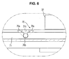
- a light window opening/closing unit 70 is disposed above the light window 31 a of the exposure unit 31 so as to expose the light window 31a only when the access door 60 is closed, thereby selectively blocking the laser beam from the exposure unit 31 to avoid the risk of injury of a user when the access door is open, and when the user is accessing the internal area of the main body 10.
- the light window opening/closing unit 70 includes a pair of slide bars 71 extending in the depth (i.e., front to rear) direction of the main body 10, and which are disposed on opposite sides of the light window 31 a.
- the slide bars 71 move in association with the opening and closing operation of the access door 60 such that, during the opening of the access door 60, the slide bars 71 move toward the opening 10a, and, during the closing of the access door 60, they move in the opposite direction, i. e., away from the opening 10a.
- a light window cover 72 having each of its opposite ends coupled to the respective one of the slide bars 71 moves together with the slide bars 71 so that the light window cover 72 is placed over, and thus covers, the light window 31 a when the access door 60 is open, and does not cover the light window 31 a when the access door 60 is closed.
- the elastic members 73 elastically bias the slide bars 71 toward the opening 10a.
- the pressing bars 74 each of which having an end thereof hingedly coupled to the access door 60, and which is arranged so that each of the other ends of the pressing bars 74 to be in alignment with the end of the respective one of the slide bars 71 when the access door 60 closes so as to push the slide bars 71 away from the opening 10a.
- the pressing bars 74 transfer a portion of a force, which is exerted on the access door 60 during the closing of the access door 60, to the slide bars 71 such that the slide bars 71 move away from the opening 10a.
- a brush 75 may be installed on the light window cover 72 to sweep and clean surface of the light window 31 a. Accordingly, as the access door 60 opens and closes, the light window 31 a can be cleaned by the brush 75.
- the image forming apparatus includes locking members 76, which secures the photosensitive cartridge 32 in place when the access door 60 is closed to prevent the photosensitive cartridge 32 from moving within the main body 10, e.g., during transporting of the image forming apparatus.
- each of the locking members 76 is rotatably installed on the slide bars 71, and are made to be rotated as the slide bars 71 move toward and away from the opening 10a to lock into place or to release the photosensitive cartridge 32.
- each of the locking members 76 includes a pair of hook members 76a together forming a V shape with a specific angle therebetween and a hinge portion 76b protruding outward from opposite sides of the portion connecting the hook members 76a, the hinge portion 76b being rotatably installed in the circular groove formed on each of the slide bars 71.
- Engaging protrusions 31 c are disposed to interfere with, and thus to cause the rotation of, the locking members 76 as the slide bars 71 move toward and away from the opening 10a, and thereby causing the locking members 76 to lock in place of release the photosensitive cartridge 32.
- Each of the engaging protrusions 31 c engages or interferes with any one of the pair of the hook members 76a to rotate the locking members 76.
- the engaging protrusions 31c are formed to protrude from opposite ends of the cover plate 31 b, which covers the upper portion of the exposure unit 31 to form the upper surface thereof.
- the slide bars 71 move away from the opening 10a while compressing or otherwise deforming the elastic members 73.
- the light window cover 72 coupled to the slide bars 71 moves in the same direction as the slide bars 71 to expose the light window 31 a so that the laser beam from the exposure unit 31 can pass to the photosensitive drum 32a through the light window 31 a.
- the locking members 76 also move away from the opening 10a together with the slide bars 71, and the hook members 76a of which formed closer to the opening 10a are interfered with by the engaging protrusions 31c, and is rotated to the horizontally extended position shown in Fig.
- the access door 60 opens, the force applied to the slide bars 71 by the pressing bars 74 is removed. Accordingly, as shown in FIG. 5 , the bias from the elastic members 73 causes the slide bars 71 to move toward the opening 10a.
- the light window cover 72 installed at the slide bars 71 covers the light window 31 a to prevent the laser beam generated in the exposure unit 31 from reaching beyond the light window cover 72.
- the brush 75 installed on the light window cover 72 sweeps the upper surface of the light window 31 a to remove foreign objects, e.g., dirt, toner particles, etc., from the upper surface of the light window 31 a. Further, while the slide bars 71 move toward the opening 10a, as shown in FIG.
- the hook members 76a further from the opening 10a are separated from the photosensitive cartridge 32 to release the photosensitive cartridge 32. Accordingly, the photosensitive cartridge 32 can be detached from the main body 10.
- the hook members 76a further from the opening 10a engage with the engaging protrusions 31 c to rotate the locking members 76 so as not to interfere with the photosensitive cartridge 32 being detached.
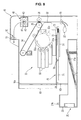
- FIG. 7 shows another embodiment of the image forming apparatus according to the present invention.
- the image forming apparatus according to this embodiment includes a second opening 10b installed on the front surface of the main body 10 such that the paper drawer 21 can move in and out of the main body 10 through the second opening 10b.
- the image forming apparatus can secure or release consumables, e.g., the photosensitive cartridge 32, installed in the main body 10 by the movement of the paper drawer 21 in and out of the main body 10.
- consumables e.g., the photosensitive cartridge 32
- the slide bars 71 move toward and away from the second opening 10b in association with the movement of the paper drawer 21 in and out of the main body 10.
- the locking members 76 installed on the slide bars 71 rotate as the slide bars 71 move to secure in place or release the consumable(s).
- one ends of the slide bars 71 are elastically biased by the elastic members 73 toward the second opening 10b.
- the other ends of the slide bars 71 are arranged to interfere with the pressing protrusions 21 b protruding upward from the paper drawer 21.
- each of the locking members 76 includes a pair of hook members 76a forming a V shape of a specific angle and a hinge portion 76b, which protrude outward from the opposite sides of the portion connecting the hook members 76a.
- Each hinge portion 76b is rotatably installed in the groove formed on the respective one of the slide bars 71.
- the engaging protrusions 31 c are disposed on the main body 10 to protrude into the main body 10 such that each of the engaging protrusions 31 c engages with any one of the pair of the hook members 76a to rotate the locking members 76.
- the paper drawer 21 moves out of the main body 10 through the second opening 10b, thereby removing the force applied to the slide bars 71 through the pressing protrusions 21 b. Accordingly, due to the elastic bias of the elastic members 73, the slide bars 71 move toward the second opening 10b. As the slide bars 71 continue to move forwarding that direction, the hook members 76a formed further from the second opening 10b are separated from the photosensitive cartridge 32 to release the photosensitive cartridge 32. Thus, the photosensitive cartridge 32 can be detached from the main body 10.
Landscapes
- Physics & Mathematics (AREA)
- General Physics & Mathematics (AREA)
- Electrophotography Configuration And Component (AREA)
Claims (7)
- Bilderzeugungsvorrichtung, aufweisend:einen Hauptkörper (10) mit einer ersten Öffnung (10a) ;ein Verbrauchsmaterial (32, 33), das lösbar im Hauptkörper (10) installiert ist;eine Tür (60), welche drehbar am Hauptkörper (10) montiert ist, um die erste Öffnung (10a) zu öffnen und zu schließen; undein Verriegelungselement (76), das im Hauptkörper (10) montiert ist, wobei das Verriegelungselement (76) so konfiguriert ist, dass es sich in Verbindung mit der Tür (60) derart bewegt, dass das Verriegelungselement (7 6) das Verbrauchsmaterial (32, 33) in Stellung sichert, wenn die Tür (60) geschlossen ist;dadurch gekennzeichnet, dass sie ferner Folgendes aufweist:eine Gleitschiene (71), die beweglich auf dem Hauptkörper (10) installiert ist, wobei die Gleitschiene (71) so konfiguriert ist, dass sie sich in Verbindung mit der Tür (60) bewegt, um sich, wenn die Tür (60) öffnet, zur Öffnung und, wenn die Tür (60) schließt, von der Öffnung weg zu bewegen,wobei das Verriegelungselement (76) drehbar auf der Gleitschiene (71) installiert ist und veranlasst wird, sich zwischen einer Verriegelungsposition und einer Freigabeposition zu drehen, wenn die Gleitschiene (71) bewegt wird, wobei das Verriegelungselement (76) in der Verriegelungsposition ist, wenn die Tür (60) geschlossen ist, und in der Freigabeposition ist, wenn die Tür (60) offen ist, un d das Verriegelungselement (76) so konfiguriert ist, dass es, wenn in der Verriegelungsposition, in das Verbrauchsmaterial (32, 33) eingreift, um zu verhindern, dass sich das Verbrauchsmaterial (32, 33) bewegt, und ferner so konfiguriert ist, dass es, wenn in der Freigabeposition, dem Verbrauchsmaterial (32, 33) ermöglicht, sich zu bewegen.
- Bilderzeugungsvorrichtung nach Anspruch 1, wobei ein erstes Ende der Gleitschiene (71) durch ein elastisches Element (73) elastisch zur Öffnung vorgespannt ist un d ei n zweites Ende der Gleitschiene (71) durch einen Pressbalken (74) gehalten wird, der an der Tür (60) montiert ist.
- Bilderzeugungsvorrichtung nach Anspruch 1 oder 2, wobei das Verriegelungselement (76) ein Paar von Hakenelementen (76a) aufweist, die einen Winkel dazwischen bilden, wobei das Paar von Hakenelementen (76a) durch einen Gelenkabschnitt (76b) verbunden ist und der Gelenkabschnitt (76b) drehbar auf der Gleitschiene (71) installiert ist.
- Bilderzeugungsvorrichtung nach Anspruch 3, ferner aufweisend:einen Eingriffsvorsprung (31c), der im Hauptkörper (10) angeordnet ist, wobei der Eingriffsvorsprung (31c) so gelegen ist, dass er in eines des Paares von Hakenelementen (76a) eingreift, wenn sich die Gleitschienen (71) zur Öffnung und davon weg bewegen, um zu bewirken, dass sich die Verriegelungselemente (76) drehen.
- Bilderzeugungsvorrichtung nach Anspruch 4, ferner aufweisend:eine Belichtungseinheit (31), die unterhalb des Verbrauchsmaterials (32, 33) angeordnet ist, wobei die Belichtungseinheit (31) ei n Lichtfenster aufweist, das auf ihrer oberen Fläche ausgebildet ist; undeine Lichtfensterabdeckung (72), die auf der Gleitschiene (71) installiert ist, um sich zusammen mit der Gleitschiene (71) in eine erste Position, die das Lichtfenster abdeckt, und eine zweite Position zu bewegen, die das Lichtfenster nicht abdeckt.
- Bilderzeugungsvorrichtung nach Anspruch 5, wobei der Eingriffsvorsprun g (31c) ein Paar von Eingriffsvorsprüngen (31c) aufweist, die von gegenüberliegenden Seiten einer Deckplatte vorstehen, die eine Oberseite der Belichtungseinheit (31) bedeckt.
- Bilderzeugungsvorrichtung nach einem der vorhergehenden Ansprüche, wo b e i das Verbrauchsmaterial (32, 33) eine lichtempfindliche Kartusche (32) mit einer lichtempfindlichen Trommel aufweist, au f welcher ein elektrostatisches Latentbild erzeugt werden soll.
Applications Claiming Priority (1)
| Application Number | Priority Date | Filing Date | Title |
|---|---|---|---|
| KR1020070070230A KR20090006660A (ko) | 2007-07-12 | 2007-07-12 | 소모품 및 이를 갖춘 화상형성기기 |
Publications (2)
| Publication Number | Publication Date |
|---|---|
| EP2015144A1 EP2015144A1 (de) | 2009-01-14 |
| EP2015144B1 true EP2015144B1 (de) | 2012-10-17 |
Family
ID=39876296
Family Applications (1)
| Application Number | Title | Priority Date | Filing Date |
|---|---|---|---|
| EP08158937A Ceased EP2015144B1 (de) | 2007-07-12 | 2008-06-25 | Bilderzeugungsvorrichtung mit Verriegelungsmitteln für Einheiten |
Country Status (5)
| Country | Link |
|---|---|
| US (2) | US8238789B2 (de) |
| EP (1) | EP2015144B1 (de) |
| JP (1) | JP5124370B2 (de) |
| KR (1) | KR20090006660A (de) |
| CN (1) | CN101344751B (de) |
Families Citing this family (11)
| Publication number | Priority date | Publication date | Assignee | Title |
|---|---|---|---|---|
| JP4868015B2 (ja) * | 2009-03-26 | 2012-02-01 | ブラザー工業株式会社 | 画像形成装置、外れ防止部材及び外れ防止構造 |
| JP5919852B2 (ja) * | 2012-01-31 | 2016-05-18 | ブラザー工業株式会社 | 画像形成装置 |
| JP5994316B2 (ja) * | 2012-03-22 | 2016-09-21 | 富士ゼロックス株式会社 | 開閉装置、画像形成装置 |
| JP6312381B2 (ja) | 2012-09-05 | 2018-04-18 | キヤノン株式会社 | 画像形成装置 |
| JP5962380B2 (ja) | 2012-09-21 | 2016-08-03 | ブラザー工業株式会社 | 画像形成装置 |
| KR101968537B1 (ko) * | 2012-11-26 | 2019-04-12 | 에이치피프린팅코리아 유한회사 | 토너 화상의 상태를 검출하는 검출장치, 이를 채용한 화상형성장치 및 이를 이용한 검출장치의 이물질 제거방법 |
| US20210081013A1 (en) | 2014-09-02 | 2021-03-18 | Delta Electronics, Inc. | Power supply apparatus |
| US11175618B2 (en) * | 2017-10-13 | 2021-11-16 | Hewlett-Packard Development Company, L.P. | Unlocking consumables from printing devices based on comparisons of values extracted from storage devices |
| JP7309342B2 (ja) | 2018-10-26 | 2023-07-18 | キヤノン株式会社 | 画像形成装置 |
| JP7254548B2 (ja) * | 2019-02-13 | 2023-04-10 | キヤノン株式会社 | 画像形成装置 |
| JP2025064083A (ja) * | 2023-10-05 | 2025-04-17 | キヤノン株式会社 | 画像形成装置 |
Family Cites Families (20)
| Publication number | Priority date | Publication date | Assignee | Title |
|---|---|---|---|---|
| JP2764322B2 (ja) | 1989-10-26 | 1998-06-11 | コニカ株式会社 | カラー画像形成装置 |
| JPH03282484A (ja) | 1990-03-30 | 1991-12-12 | Canon Inc | プロセスカートリッジの着脱方法 |
| JPH04116668A (ja) * | 1990-09-07 | 1992-04-17 | Konica Corp | 画像形成装置 |
| JP3282484B2 (ja) | 1996-03-15 | 2002-05-13 | 三菱電機株式会社 | 通信方法、通信システム、送信装置および受信装置 |
| JP3140971B2 (ja) | 1996-10-17 | 2001-03-05 | 株式会社ナムコ | ゲームコントローラ |
| JP2000263839A (ja) | 1999-03-11 | 2000-09-26 | Fuji Xerox Co Ltd | 画像形成装置 |
| JP2004038054A (ja) * | 2002-07-08 | 2004-02-05 | Seiko Epson Corp | 画像形成装置における光学センサの半自動クリーニング機構 |
| KR100423492B1 (ko) * | 2002-07-02 | 2004-03-18 | 삼성전자주식회사 | 프린터의 감광체 유닛 착탈장치 |
| KR100462613B1 (ko) * | 2002-07-09 | 2004-12-20 | 삼성전자주식회사 | 인쇄기의 감광유닛 및 전사유닛 교환 시스템 |
| JP4193545B2 (ja) * | 2003-03-31 | 2008-12-10 | ブラザー工業株式会社 | 画像形成装置 |
| KR100547130B1 (ko) * | 2003-07-04 | 2006-01-26 | 삼성전자주식회사 | 전자사진방식 인쇄기 |
| US7266327B2 (en) | 2003-07-25 | 2007-09-04 | Brother Kogyo Kabushiki Kaisha | Image-forming device having a removable process cartridge |
| US7724276B2 (en) | 2003-11-03 | 2010-05-25 | Hewlett-Packard Development Company, L.P. | Optical assembly lock/unlock apparatus and method |
| JP4474182B2 (ja) * | 2004-03-15 | 2010-06-02 | キヤノン株式会社 | モジュール用把持装置及びそれを備えた画像形成装置 |
| KR101014666B1 (ko) | 2004-05-18 | 2011-02-16 | 삼성전자주식회사 | 전자사진방식 화상형성장치 |
| JP2006064888A (ja) | 2004-08-25 | 2006-03-09 | Kyocera Mita Corp | 画像形成装置 |
| JP2006215225A (ja) | 2005-02-03 | 2006-08-17 | Fuji Xerox Co Ltd | 画像形成装置 |
| KR100785085B1 (ko) | 2005-02-07 | 2007-12-12 | 삼성전자주식회사 | 화상형성장치 및 화상독취장치. |
| JP4432813B2 (ja) * | 2005-03-24 | 2010-03-17 | ブラザー工業株式会社 | 画像形成装置 |
| KR100659271B1 (ko) * | 2005-11-14 | 2006-12-20 | 삼성전자주식회사 | 전사유닛 고정장치, 및 그것을 구비한 화상형성장치 |
-
2007
- 2007-07-12 KR KR1020070070230A patent/KR20090006660A/ko not_active Ceased
-
2008
- 2008-06-12 US US12/137,994 patent/US8238789B2/en not_active Expired - Fee Related
- 2008-06-24 CN CN2008101318092A patent/CN101344751B/zh not_active Expired - Fee Related
- 2008-06-25 EP EP08158937A patent/EP2015144B1/de not_active Ceased
- 2008-07-03 JP JP2008174682A patent/JP5124370B2/ja not_active Expired - Fee Related
-
2012
- 2012-07-26 US US13/558,488 patent/US8483596B2/en not_active Expired - Fee Related
Also Published As
| Publication number | Publication date |
|---|---|
| US8238789B2 (en) | 2012-08-07 |
| US20120301183A1 (en) | 2012-11-29 |
| US8483596B2 (en) | 2013-07-09 |
| US20090016768A1 (en) | 2009-01-15 |
| JP2009020515A (ja) | 2009-01-29 |
| CN101344751B (zh) | 2010-12-15 |
| CN101344751A (zh) | 2009-01-14 |
| JP5124370B2 (ja) | 2013-01-23 |
| EP2015144A1 (de) | 2009-01-14 |
| KR20090006660A (ko) | 2009-01-15 |
Similar Documents
| Publication | Publication Date | Title |
|---|---|---|
| EP2015144B1 (de) | Bilderzeugungsvorrichtung mit Verriegelungsmitteln für Einheiten | |
| CN101211154B (zh) | 电摄影成像设备和处理盒 | |
| RU2431171C2 (ru) | Технологический картридж и электрофотографическое устройство формирования изображения | |
| EP1722279B1 (de) | Prozesskartusche mit abnehmbarer Tonerkartusche, die eine Kraft auf den Entwicklungsroller in Richtung des Bildträgers ausübt | |
| US9501031B2 (en) | Packaged cartridge, packing material and cartridge | |
| US9383709B2 (en) | Electrophotographic image forming apparatus and supporting member | |
| US9442458B2 (en) | Image forming apparatus | |
| US7817936B2 (en) | Color electrophotographic image forming apparatus | |
| EP2012189B1 (de) | Entwicklungsvorrichtung, Abfalltonersammelvorrichtung und Bilderzeugungsvorrichtung damit | |
| JP4317313B2 (ja) | 現像モジュールの自動カミング機構及びこれを備えた現像ユニット並びに印刷機 | |
| US5307117A (en) | Protective shipping cover for CRU | |
| US20110142489A1 (en) | Electrophotographic image forming apparatus | |
| EP2093632B1 (de) | Lichtempfindliche Körpereinheit und damit ausgerüstete Bilderzeugungsvorrichtung | |
| JP5550462B2 (ja) | プロセスカートリッジ | |
| US6091916A (en) | Retractable shield for a photosensitive member | |
| JP4282816B2 (ja) | カバー、プリントカートリッジ、及び電子写真プリント装置 | |
| US7555240B2 (en) | Cover members for an image forming apparatus | |
| JP3979641B2 (ja) | 画像形成装置 | |
| US6873811B2 (en) | Printer imaging components protection apparatus and method | |
| JP7059629B2 (ja) | 画像形成装置 | |
| US9851684B2 (en) | Engaging mechanism for movable panel in image forming apparatus | |
| JP7799423B2 (ja) | 画像形成装置 | |
| KR100601889B1 (ko) | 복수의 유닛으로 구성된 현상유닛을 구비한 화상형성장치 | |
| JP2000010456A (ja) | 画像形成装置 | |
| JP6972836B2 (ja) | 粉体処理装置および画像形成装置 |
Legal Events
| Date | Code | Title | Description |
|---|---|---|---|
| PUAI | Public reference made under article 153(3) epc to a published international application that has entered the european phase |
Free format text: ORIGINAL CODE: 0009012 |
|
| AK | Designated contracting states |
Kind code of ref document: A1 Designated state(s): AT BE BG CH CY CZ DE DK EE ES FI FR GB GR HR HU IE IS IT LI LT LU LV MC MT NL NO PL PT RO SE SI SK TR |
|
| AX | Request for extension of the european patent |
Extension state: AL BA MK RS |
|
| 17P | Request for examination filed |
Effective date: 20090616 |
|
| 17Q | First examination report despatched |
Effective date: 20090715 |
|
| AKX | Designation fees paid |
Designated state(s): DE FR GB NL |
|
| GRAJ | Information related to disapproval of communication of intention to grant by the applicant or resumption of examination proceedings by the epo deleted |
Free format text: ORIGINAL CODE: EPIDOSDIGR1 |
|
| GRAP | Despatch of communication of intention to grant a patent |
Free format text: ORIGINAL CODE: EPIDOSNIGR1 |
|
| GRAP | Despatch of communication of intention to grant a patent |
Free format text: ORIGINAL CODE: EPIDOSNIGR1 |
|
| GRAS | Grant fee paid |
Free format text: ORIGINAL CODE: EPIDOSNIGR3 |
|
| GRAA | (expected) grant |
Free format text: ORIGINAL CODE: 0009210 |
|
| RAP1 | Party data changed (applicant data changed or rights of an application transferred) |
Owner name: SAMSUNG ELECTRONICS CO., LTD. |
|
| AK | Designated contracting states |
Kind code of ref document: B1 Designated state(s): DE FR GB NL |
|
| REG | Reference to a national code |
Ref country code: GB Ref legal event code: FG4D |
|
| REG | Reference to a national code |
Ref country code: DE Ref legal event code: R096 Ref document number: 602008019398 Country of ref document: DE Effective date: 20121213 |
|
| REG | Reference to a national code |
Ref country code: NL Ref legal event code: T3 |
|
| PLBE | No opposition filed within time limit |
Free format text: ORIGINAL CODE: 0009261 |
|
| STAA | Information on the status of an ep patent application or granted ep patent |
Free format text: STATUS: NO OPPOSITION FILED WITHIN TIME LIMIT |
|
| 26N | No opposition filed |
Effective date: 20130718 |
|
| REG | Reference to a national code |
Ref country code: DE Ref legal event code: R097 Ref document number: 602008019398 Country of ref document: DE Effective date: 20130718 |
|
| REG | Reference to a national code |
Ref country code: FR Ref legal event code: PLFP Year of fee payment: 9 |
|
| REG | Reference to a national code |
Ref country code: NL Ref legal event code: PD Owner name: S-PRINTING SOLUTION CO., LTD.; KO Free format text: DETAILS ASSIGNMENT: CHANGE OF OWNER(S), ASSIGNMENT; FORMER OWNER NAME: SAMSUNG ELECTRONICS CO., LTD. Effective date: 20170221 |
|
| REG | Reference to a national code |
Ref country code: GB Ref legal event code: 732E Free format text: REGISTERED BETWEEN 20170406 AND 20170412 |
|
| REG | Reference to a national code |
Ref country code: FR Ref legal event code: PLFP Year of fee payment: 10 |
|
| REG | Reference to a national code |
Ref country code: DE Ref legal event code: R082 Ref document number: 602008019398 Country of ref document: DE Representative=s name: GULDE & PARTNER PATENT- UND RECHTSANWALTSKANZL, DE Ref country code: DE Ref legal event code: R082 Ref document number: 602008019398 Country of ref document: DE Ref country code: DE Ref legal event code: R081 Ref document number: 602008019398 Country of ref document: DE Owner name: HP PRINTING KOREA CO., LTD., SUWON-SI, KR Free format text: FORMER OWNER: SAMSUNG ELECTRONICS CO., LTD., SUWON-SI, GYEONGGI-DO, KR Ref country code: DE Ref legal event code: R081 Ref document number: 602008019398 Country of ref document: DE Owner name: HEWLETT-PACKARD DEVELOPMENT COMPANY, L.P., SPR, US Free format text: FORMER OWNER: SAMSUNG ELECTRONICS CO., LTD., SUWON-SI, GYEONGGI-DO, KR Ref country code: DE Ref legal event code: R082 Ref document number: 602008019398 Country of ref document: DE Representative=s name: SCHOPPE, ZIMMERMANN, STOECKELER, ZINKLER, SCHE, DE Ref country code: DE Ref legal event code: R081 Ref document number: 602008019398 Country of ref document: DE Owner name: S-PRINTING SOLUTION CO., LTD., SUWON-SI, KR Free format text: FORMER OWNER: SAMSUNG ELECTRONICS CO., LTD., SUWON-SI, GYEONGGI-DO, KR |
|
| REG | Reference to a national code |
Ref country code: FR Ref legal event code: TP Owner name: S-PRINTING SOLUTION CO., LTD., KR Effective date: 20170912 |
|
| REG | Reference to a national code |
Ref country code: FR Ref legal event code: PLFP Year of fee payment: 11 |
|
| REG | Reference to a national code |
Ref country code: NL Ref legal event code: HC Owner name: HP PRINTING KOREA CO., LTD.; KR Free format text: DETAILS ASSIGNMENT: CHANGE OF OWNER(S), CHANGE OF OWNER(S) NAME; FORMER OWNER NAME: S-PRINTING SOLUTION CO., LTD. Effective date: 20180816 |
|
| REG | Reference to a national code |
Ref country code: DE Ref legal event code: R082 Ref document number: 602008019398 Country of ref document: DE Ref country code: DE Ref legal event code: R081 Ref document number: 602008019398 Country of ref document: DE Owner name: HP PRINTING KOREA CO., LTD., SUWON-SI, KR Free format text: FORMER OWNER: S-PRINTING SOLUTION CO., LTD., SUWON-SI, GYEONGGI-DO, KR Ref country code: DE Ref legal event code: R081 Ref document number: 602008019398 Country of ref document: DE Owner name: HEWLETT-PACKARD DEVELOPMENT COMPANY, L.P., SPR, US Free format text: FORMER OWNER: S-PRINTING SOLUTION CO., LTD., SUWON-SI, GYEONGGI-DO, KR Ref country code: DE Ref legal event code: R082 Ref document number: 602008019398 Country of ref document: DE Representative=s name: SCHOPPE, ZIMMERMANN, STOECKELER, ZINKLER, SCHE, DE |
|
| REG | Reference to a national code |
Ref country code: NL Ref legal event code: PD Owner name: HEWLETT-PACKARD DEVELOPMENT COMPANY, L.P.; US Free format text: DETAILS ASSIGNMENT: CHANGE OF OWNER(S), CHANGE OF LEGAL ENTITY; FORMER OWNER NAME: SAMSUNG ELECTRONICS CO., LTD. Effective date: 20191030 |
|
| REG | Reference to a national code |
Ref country code: DE Ref legal event code: R081 Ref document number: 602008019398 Country of ref document: DE Owner name: HEWLETT-PACKARD DEVELOPMENT COMPANY, L.P., SPR, US Free format text: FORMER OWNER: HP PRINTING KOREA CO., LTD., SUWON-SI, GYEONGGI-DO, KR |
|
| REG | Reference to a national code |
Ref country code: GB Ref legal event code: 732E Free format text: REGISTERED BETWEEN 20191212 AND 20191218 |
|
| PGFP | Annual fee paid to national office [announced via postgrant information from national office to epo] |
Ref country code: FR Payment date: 20201214 Year of fee payment: 14 |
|
| PGFP | Annual fee paid to national office [announced via postgrant information from national office to epo] |
Ref country code: DE Payment date: 20201214 Year of fee payment: 14 Ref country code: NL Payment date: 20210520 Year of fee payment: 14 |
|
| REG | Reference to a national code |
Ref country code: DE Ref legal event code: R082 Ref document number: 602008019398 Country of ref document: DE Representative=s name: SCHOPPE, ZIMMERMANN, STOECKELER, ZINKLER, SCHE, DE |
|
| PGFP | Annual fee paid to national office [announced via postgrant information from national office to epo] |
Ref country code: GB Payment date: 20210519 Year of fee payment: 14 |
|
| REG | Reference to a national code |
Ref country code: DE Ref legal event code: R119 Ref document number: 602008019398 Country of ref document: DE |
|
| REG | Reference to a national code |
Ref country code: NL Ref legal event code: MM Effective date: 20220701 |
|
| GBPC | Gb: european patent ceased through non-payment of renewal fee |
Effective date: 20220625 |
|
| PG25 | Lapsed in a contracting state [announced via postgrant information from national office to epo] |
Ref country code: NL Free format text: LAPSE BECAUSE OF NON-PAYMENT OF DUE FEES Effective date: 20220701 |
|
| PG25 | Lapsed in a contracting state [announced via postgrant information from national office to epo] |
Ref country code: FR Free format text: LAPSE BECAUSE OF NON-PAYMENT OF DUE FEES Effective date: 20220630 |
|
| PG25 | Lapsed in a contracting state [announced via postgrant information from national office to epo] |
Ref country code: GB Free format text: LAPSE BECAUSE OF NON-PAYMENT OF DUE FEES Effective date: 20220625 Ref country code: DE Free format text: LAPSE BECAUSE OF NON-PAYMENT OF DUE FEES Effective date: 20230103 |