EP2014530A2 - Vorrichtung für die Kurven-Regelung eines Fahrzeugs - Google Patents
Vorrichtung für die Kurven-Regelung eines Fahrzeugs Download PDFInfo
- Publication number
- EP2014530A2 EP2014530A2 EP08153158A EP08153158A EP2014530A2 EP 2014530 A2 EP2014530 A2 EP 2014530A2 EP 08153158 A EP08153158 A EP 08153158A EP 08153158 A EP08153158 A EP 08153158A EP 2014530 A2 EP2014530 A2 EP 2014530A2
- Authority
- EP
- European Patent Office
- Prior art keywords
- control
- vehicle
- wheel
- turning
- case
- Prior art date
- Legal status (The legal status is an assumption and is not a legal conclusion. Google has not performed a legal analysis and makes no representation as to the accuracy of the status listed.)
- Granted
Links
Images


Classifications
-
- B—PERFORMING OPERATIONS; TRANSPORTING
- B60—VEHICLES IN GENERAL
- B60T—VEHICLE BRAKE CONTROL SYSTEMS OR PARTS THEREOF; BRAKE CONTROL SYSTEMS OR PARTS THEREOF, IN GENERAL; ARRANGEMENT OF BRAKING ELEMENTS ON VEHICLES IN GENERAL; PORTABLE DEVICES FOR PREVENTING UNWANTED MOVEMENT OF VEHICLES; VEHICLE MODIFICATIONS TO FACILITATE COOLING OF BRAKES
- B60T8/00—Arrangements for adjusting wheel-braking force to meet varying vehicular or ground-surface conditions, e.g. limiting or varying distribution of braking force
- B60T8/24—Arrangements for adjusting wheel-braking force to meet varying vehicular or ground-surface conditions, e.g. limiting or varying distribution of braking force responsive to vehicle inclination or change of direction, e.g. negotiating bends
- B60T8/246—Change of direction
-
- B—PERFORMING OPERATIONS; TRANSPORTING
- B60—VEHICLES IN GENERAL
- B60T—VEHICLE BRAKE CONTROL SYSTEMS OR PARTS THEREOF; BRAKE CONTROL SYSTEMS OR PARTS THEREOF, IN GENERAL; ARRANGEMENT OF BRAKING ELEMENTS ON VEHICLES IN GENERAL; PORTABLE DEVICES FOR PREVENTING UNWANTED MOVEMENT OF VEHICLES; VEHICLE MODIFICATIONS TO FACILITATE COOLING OF BRAKES
- B60T8/00—Arrangements for adjusting wheel-braking force to meet varying vehicular or ground-surface conditions, e.g. limiting or varying distribution of braking force
- B60T8/17—Using electrical or electronic regulation means to control braking
- B60T8/1755—Brake regulation specially adapted to control the stability of the vehicle, e.g. taking into account yaw rate or transverse acceleration in a curve
-
- B—PERFORMING OPERATIONS; TRANSPORTING
- B60—VEHICLES IN GENERAL
- B60T—VEHICLE BRAKE CONTROL SYSTEMS OR PARTS THEREOF; BRAKE CONTROL SYSTEMS OR PARTS THEREOF, IN GENERAL; ARRANGEMENT OF BRAKING ELEMENTS ON VEHICLES IN GENERAL; PORTABLE DEVICES FOR PREVENTING UNWANTED MOVEMENT OF VEHICLES; VEHICLE MODIFICATIONS TO FACILITATE COOLING OF BRAKES
- B60T8/00—Arrangements for adjusting wheel-braking force to meet varying vehicular or ground-surface conditions, e.g. limiting or varying distribution of braking force
- B60T8/24—Arrangements for adjusting wheel-braking force to meet varying vehicular or ground-surface conditions, e.g. limiting or varying distribution of braking force responsive to vehicle inclination or change of direction, e.g. negotiating bends
-
- B—PERFORMING OPERATIONS; TRANSPORTING
- B60—VEHICLES IN GENERAL
- B60T—VEHICLE BRAKE CONTROL SYSTEMS OR PARTS THEREOF; BRAKE CONTROL SYSTEMS OR PARTS THEREOF, IN GENERAL; ARRANGEMENT OF BRAKING ELEMENTS ON VEHICLES IN GENERAL; PORTABLE DEVICES FOR PREVENTING UNWANTED MOVEMENT OF VEHICLES; VEHICLE MODIFICATIONS TO FACILITATE COOLING OF BRAKES
- B60T8/00—Arrangements for adjusting wheel-braking force to meet varying vehicular or ground-surface conditions, e.g. limiting or varying distribution of braking force
- B60T8/32—Arrangements for adjusting wheel-braking force to meet varying vehicular or ground-surface conditions, e.g. limiting or varying distribution of braking force responsive to a speed condition, e.g. acceleration or deceleration
- B60T8/321—Arrangements for adjusting wheel-braking force to meet varying vehicular or ground-surface conditions, e.g. limiting or varying distribution of braking force responsive to a speed condition, e.g. acceleration or deceleration deceleration
- B60T8/322—Systems specially adapted for vehicles driven by more than one axle, e.g. Four Wheel-Drive vehicles
-
- B—PERFORMING OPERATIONS; TRANSPORTING
- B60—VEHICLES IN GENERAL
- B60W—CONJOINT CONTROL OF VEHICLE SUB-UNITS OF DIFFERENT TYPE OR DIFFERENT FUNCTION; CONTROL SYSTEMS SPECIALLY ADAPTED FOR HYBRID VEHICLES; ROAD VEHICLE DRIVE CONTROL SYSTEMS FOR PURPOSES NOT RELATED TO THE CONTROL OF A PARTICULAR SUB-UNIT
- B60W30/00—Purposes of road vehicle drive control systems not related to the control of a particular sub-unit, e.g. of systems using conjoint control of vehicle sub-units
- B60W30/02—Control of vehicle driving stability
- B60W30/045—Improving turning performance
-
- B—PERFORMING OPERATIONS; TRANSPORTING
- B60—VEHICLES IN GENERAL
- B60W—CONJOINT CONTROL OF VEHICLE SUB-UNITS OF DIFFERENT TYPE OR DIFFERENT FUNCTION; CONTROL SYSTEMS SPECIALLY ADAPTED FOR HYBRID VEHICLES; ROAD VEHICLE DRIVE CONTROL SYSTEMS FOR PURPOSES NOT RELATED TO THE CONTROL OF A PARTICULAR SUB-UNIT
- B60W30/00—Purposes of road vehicle drive control systems not related to the control of a particular sub-unit, e.g. of systems using conjoint control of vehicle sub-units
- B60W30/18—Propelling the vehicle
- B60W30/188—Controlling power parameters of the driveline, e.g. determining the required power
-
- B—PERFORMING OPERATIONS; TRANSPORTING
- B60—VEHICLES IN GENERAL
- B60W—CONJOINT CONTROL OF VEHICLE SUB-UNITS OF DIFFERENT TYPE OR DIFFERENT FUNCTION; CONTROL SYSTEMS SPECIALLY ADAPTED FOR HYBRID VEHICLES; ROAD VEHICLE DRIVE CONTROL SYSTEMS FOR PURPOSES NOT RELATED TO THE CONTROL OF A PARTICULAR SUB-UNIT
- B60W40/00—Estimation or calculation of non-directly measurable driving parameters for road vehicle drive control systems not related to the control of a particular sub unit, e.g. by using mathematical models
- B60W40/10—Estimation or calculation of non-directly measurable driving parameters for road vehicle drive control systems not related to the control of a particular sub unit, e.g. by using mathematical models related to vehicle motion
- B60W40/114—Yaw movement
-
- B—PERFORMING OPERATIONS; TRANSPORTING
- B60—VEHICLES IN GENERAL
- B60T—VEHICLE BRAKE CONTROL SYSTEMS OR PARTS THEREOF; BRAKE CONTROL SYSTEMS OR PARTS THEREOF, IN GENERAL; ARRANGEMENT OF BRAKING ELEMENTS ON VEHICLES IN GENERAL; PORTABLE DEVICES FOR PREVENTING UNWANTED MOVEMENT OF VEHICLES; VEHICLE MODIFICATIONS TO FACILITATE COOLING OF BRAKES
- B60T2201/00—Particular use of vehicle brake systems; Special systems using also the brakes; Special software modules within the brake system controller
- B60T2201/14—Electronic locking-differential
-
- B—PERFORMING OPERATIONS; TRANSPORTING
- B60—VEHICLES IN GENERAL
- B60W—CONJOINT CONTROL OF VEHICLE SUB-UNITS OF DIFFERENT TYPE OR DIFFERENT FUNCTION; CONTROL SYSTEMS SPECIALLY ADAPTED FOR HYBRID VEHICLES; ROAD VEHICLE DRIVE CONTROL SYSTEMS FOR PURPOSES NOT RELATED TO THE CONTROL OF A PARTICULAR SUB-UNIT
- B60W10/00—Conjoint control of vehicle sub-units of different type or different function
- B60W10/04—Conjoint control of vehicle sub-units of different type or different function including control of propulsion units
-
- B—PERFORMING OPERATIONS; TRANSPORTING
- B60—VEHICLES IN GENERAL
- B60W—CONJOINT CONTROL OF VEHICLE SUB-UNITS OF DIFFERENT TYPE OR DIFFERENT FUNCTION; CONTROL SYSTEMS SPECIALLY ADAPTED FOR HYBRID VEHICLES; ROAD VEHICLE DRIVE CONTROL SYSTEMS FOR PURPOSES NOT RELATED TO THE CONTROL OF A PARTICULAR SUB-UNIT
- B60W10/00—Conjoint control of vehicle sub-units of different type or different function
- B60W10/12—Conjoint control of vehicle sub-units of different type or different function including control of differentials
-
- B—PERFORMING OPERATIONS; TRANSPORTING
- B60—VEHICLES IN GENERAL
- B60W—CONJOINT CONTROL OF VEHICLE SUB-UNITS OF DIFFERENT TYPE OR DIFFERENT FUNCTION; CONTROL SYSTEMS SPECIALLY ADAPTED FOR HYBRID VEHICLES; ROAD VEHICLE DRIVE CONTROL SYSTEMS FOR PURPOSES NOT RELATED TO THE CONTROL OF A PARTICULAR SUB-UNIT
- B60W10/00—Conjoint control of vehicle sub-units of different type or different function
- B60W10/18—Conjoint control of vehicle sub-units of different type or different function including control of braking systems
Definitions
- the present invention relates to a turning behavior control device of a vehicle.
- Japanese Patent Publication No. 2007-131229A described later discloses a technique in which a difference of the drive force between the right and the left wheel is fed back according to a yaw rate of a vehicle and a braking force given to each wheel of the vehicle is also fed back.
- electronic control LSD Lited Slip Differential
- a center differential gear in which a degree of the limitation of the differential between the front and the rear wheel is variable, is fed back according to the yaw rate of a vehicle.
- under-steering is generated when a vehicle of 4-wheel drive is turning
- this method since a traction of the entire vehicle is decreased, the accelerating performance of the vehicle is lowered. That is, on the assumption that the rear wheel of the vehicle has slipped under the condition that a differential between the front and the rear wheel made by the center differential gear is not limited, the rear wheel is further rotated. Therefore, torque originally to be transmitted to the front wheel is transmitted to the rear wheel which is slipping. Accordingly, the vehicle is limited from being accelerated.
- the present applicant proposed the following control technique which is described in Japanese Patent Publication No. 2007-131229A .
- a limitation of the differential between the front and the rear wheel is made by the front and rear differential limitation device and a drive force control between the right and the left wheel of the vehicle is made by the right and left wheel torque difference generating device and further the brake device is integrally controlled. Only when over-steering is suppressed, in parallel with the control of the drive force between the right and the left wheel of the vehicle, controlling is executed so that a restricting force generated by the differential control between the front and the rear wheel made by the central differential gear is strengthened.
- the yawing control is made by a right and left wheel torque difference generating device like the conventional constitution
- a load given to the rear wheel is decreased at the time of deceleration, a controlling capacity is lowered.
- the suppression of over-steering made by a torque difference between the right and the left wheel on the rear side facilitates over-steering by a reduction of the lateral force of the rear wheel on the contrary.
- a device operable to control a turning of a vehicle including: a first adjuster, operable to adjust a drive force applied to at least one of front wheels and rear wheels of the vehicle; a second adjuster, operable to adjust a braking force applied to at least one of the front wheels and the rear wheels; and a motion controller, operable to provide a control amount which is distributed to the first adjuster with a first ratio and to the second adjuster with a second ratio, the motion controller operable to: control the first adjuster so as to increase the drive force applied to the at least one of the front wheels and the rear wheels situated in an inner side of the turning; and control the second adjuster so as to increase the braking force applied to at least one of the front wheels and the rear wheels situated in an outer side of the turning, in order to suppress yawing of the vehicle; control the first adjuster so as to increase the drive force applied to at least one of the front wheels and the rear wheels situated in an outer side of the turning; and control the second adjuster
- a braking force given to the inner turning wheel is increased together with an increase in a drive force given to the inner turning wheel.
- a drive force given to the outer turning wheel is increased and a braking force given to the inner turning wheel is increased. Accordingly, it is possible to enhance the turning performance of the vehicle.
- a ratio of the amount of control distributed to the first adjuster is made to be higher than that in the case of suppressing a yawing motion of the vehicle, so that a drive force of the outer turning wheel, the ground contact load of which is heavy, is more highly increased so as to effectively execute the yawing motion control.
- a ratio of the amount of control distributed to the second adjuster is made to be higher than that in the case of facilitating a yawing motion of the vehicle, so that a braking force of the outer turning wheel, the ground contact load of which is heavy, is more highly increased so as to effectively execute the yawing motion control. Therefore, it is possible to stabilize the turning performance.
- the device may include a detector, operable to detect an acceleration and deceleration of the vehicle, wherein: the motion controller is operable to increase the first ratio in a case that the detector detects the acceleration; and the motion controller is operable to increase the second ratio in a case that the detector detects the deceleration.
- a ratio of the amount of control distributed to the first adjuster is made higher than that in the case of deceleration. Therefore, at the time of acceleration in which a ground contact load given to the wheel becomes heavy, the drive force is increased so that the yawing motion control can be highly efficiently executed. Therefore, while a feeling of deceleration is being reduced at the time of acceleration, it is possible to stabilize the turning performance of the vehicle. Accordingly, it is possible to more highly enhance the drive feeling.
- a ratio of the amount of control distributed to the second adjuster is made to be higher than that of the case of acceleration.
- the device may include a detector, operable to detect a velocity of the vehicle, wherein: the motion controller is operable to increase the first ratio in a case that the velocity detected by the detector is less than a prescribed value; and the motion controller is operable to increase the second ratio in a case that the velocity detected by the detector is no less than the prescribed value.
- a ratio of the amount of control distributed to the first adjuster is made to be higher than that of the case of a high velocity.
- a ratio of the amount of control distributed to the second adjuster is made to be higher than that of the case of a low velocity. Therefore, while a feeling of deceleration caused by an excessively high increase in the braking force is being suppressed, under-steering and over-steering can be properly suppressed and the turning performance of the vehicle can be enhanced.
- FIG. 1 The turning behavior control device shown in Fig. 1 is applied to a four-wheel drive type vehicle 1.
- An output of the engine 2 mounted on the vehicle 1 is transmitted to the right front wheel 8R and the left front wheel 8L through the transmission 3, the intermediate gear mechanism 4, the front differential gear 6 and the axles 7R, 7L.
- the output of the engine 2 mounted on the vehicle 1 is transmitted to the right rear wheel 14R and the left rear wheel 14L through the hypoid gear mechanism 9 on the front wheel side, the propeller shaft 10, the hypoid gear mechanism 11 on the rear wheel side, the rear differential gear 12 and the axles 13R, 13L.
- this rear differential gear 12 includes a drive force moving mechanism 15 for moving a drive force between the right and the left wheel, the detail of which will be described later.
- the front differential gear 6 is a torque induction type differential gear which mechanically restricts a differential motion made between the right 8R and the left wheel 8L according to an intensity of torque inputted from the engine 2.
- the rear differential gear 12 is provided which allows a differential motion made between the right wheel 14R and the left wheel 14L.
- the drive force moving mechanism 15 for moving a drive force between the right and the left wheel is provided, by which a difference of the drive force to be transmitted to the right wheel 14R and the left wheel 14R can be appropriately changed.
- the crown gear 16 which is meshed with the pinion gear 10A provided at a rear end portion of the propeller shaft 10, is arranged.
- the planetary gear mechanism 12B is provided inside the case 12A.
- a differential motion between the right wheel 14R and the left wheel 14L is allowed. Accordingly, torque, which has been inputted from the engine 2 into the crown gear 16 through the propeller shaft 10 and the pinion gear 10A, is transmitted to both wheels 14R, 14L while a differential motion between the right rear wheel 14R and the left rear wheel 14L is being allowed by the planetary gear mechanism 12B.
- the drive force moving mechanism 15 for moving a drive force between the right and the left wheel includes: a change gear mechanism 15A; and a torque transmission mechanism 15B of a variable transmission capacity control type.
- a change gear mechanism 15A By a command given from ECU 40 mounted on the vehicle 1, a difference between the drive force of the right wheel 14R and that of the left wheel 14L can be appropriately changed according to a running state of the vehicle.
- the change gear mechanism 15A increases and decreases a rotary speed of one of the right and the left wheel (in this case, a rotary speed of the left wheel 14L) and outputs it to the torque transmission mechanism 15B.
- This variable transmission capacity control type torque transmission mechanism 15B is a wet hydraulic type multiple disk clutch mechanism capable of adjusting a transmission torque capacity according to hydraulic pressure inputted from a drive system hydraulic unit controlled by ECU 40.
- This variable transmission capacity control type torque transmission mechanism 15B is operated as follows. By utilizing a difference between the rotary speed, which is increased or decreased by the change gear 15A, and the rotary speed of the other wheel (in the present embodiment, the right wheel 14R) in the right and the left wheel, torque is given and received between the right wheel 14R and the left wheel 14L. Due o the foregoing, an intensity of torque of one wheel is increased or decreased and an intensity of torque of the other wheel is decreased or increased.
- a predetermined hydraulic pressure is inputted from a drive system hydraulic unit (not shown) into the drive force moving mechanism 15 for moving a drive force between the right and the left wheel of the rear differential gear 12.
- the predetermined hydraulic pressure is transmitted to the right wheel 14R and the torque is decreased, the right rear wheel 14R is decelerated.
- torque transmitted to the left rear wheel 14L is increased and the left rear wheel 14L is accelerated. Accordingly, it is possible to generate a yaw moment, the direction of which is clockwise, in the vehicle 1.
- the above drive system hydraulic unit not shown in the drawing includes: an accumulator; a motor pump for pressurizing hydraulic oil in the accumulator at a predetermined pressure; a pressure sensor for monitoring hydraulic pressure pressurized by the motor pump; an electromagnetic control valve for adjusting hydraulic pressure in the accumulator which has already been adjusted by the motor pump; and a direction change-over valve for changing over the hydraulic pressure, which has been adjusted by the electromagnetic control valve, between a predetermined hydraulic chamber (not shown) of the drive force moving mechanism 15 for moving a drive force between the right and the left wheel and a predetermined hydraulic chamber (not shown) of the differential motion restricting mechanism for restricting a differential motion between the front 19 and the rear wheel.
- the rear differential gear controller 31 (a first adjuster) is an electronic control unit having an interface, memory and CPU which are not shown in the drawing.
- This rear differential gear controller 31 is operated as follows.
- a signal (a drive force distribution signal) showing a hydraulic pressure corresponding to a drive force difference between the right rear wheel 14R and the left rear wheel 14L and also showing an output destination of the hydraulic pressure is sent to the drive system hydraulic unit.
- the drive system hydraulic unit which has received this drive force difference signal, appropriately controls hydraulic pressure for the drive force moving mechanism 15 for moving a drive force between the right and the left wheel of the rear differential gear 12, a difference of the drive force between the right rear wheel 14R and the left rear wheel 14L is adjusted.
- Wheels 8L, 8R, 14L, 14R of the vehicle 1 respectively have braking devices 21L, 21R, 22L, 22R.
- Control system hydraulic units for independently supplying hydraulic pressure to the braking devices 21L, 21R, 22L, 22R are provided.
- This vehicle 1 has a brake device controller (a second adjuster) 33.
- This brake device controller 33 is an electronic control unit having an interface, memory and CPU which are not shown in the drawing.
- This brake device controller 33 sends a signal (a brake increasing and decreasing pressure signal), which shows hydraulic pressure to be increased and decreased with respect to the four respective brake devices 21L, 21R, 22L, 22R arranged in the wheels 8L, 8R, 14L, 14R, to a control system hydraulic unit (not shown).
- the control system hydraulic unit which has received this brake increase and decrease pressure signal, appropriately controls hydraulic pressure inputted into the brake device 21L, 21R, 22L, 22R.
- This braking system hydraulic unit includes a motor pump and an electromagnetic control valve for adjusting braking hydraulic pressure, so that a predetermined hydraulic pressure can be inputted into each braking unit 21L, 21R, 22L, 22R according to a direction given from the braking unit controller 33.
- the rear differential controller 31 and the braking unit controller 33 are connected to ECU 40 through signal lines and operated according to a control signal sent from ECU 40.
- ECU 40 is an electronic control unit having an interface, memory and CPU which are not shown in the drawing. ECU 40 can read in the result of the detection made by the vehicle speed sensor (a detector) 45L, 45R, 46L, 46R, the steering angle sensor 47, G sensor (a detector) 48 and the yaw rate sensor 49.
- vehicle speed sensor a detector
- 45L, 45R, 46L, 46R the steering angle sensor 47
- G sensor a detector
- This ECU 40 includes a control yaw moment calculation portion 41, an under-steering/over-steering judging portion (US/OS judging) 42 and a yawing motion control portion (a motion controller) 43 which are programs recorded in a memory not shown.
- the yawing motion control map 44 used by the yawing motion control portion 43 is recorded in this memory.
- the control yaw moment calculation portion 41 is provided for finding a control yaw moment which is a yaw moment to be added so that the vehicle 1 can be turned by a turning radius at which the driver intends to turn the vehicle.
- this control yaw moment calculation portion 41 calculates a target yaw rate (target yaw momentum correlation value) according to a steering angle, which is measured by the steering angle sensor 47, and a vehicle speed which is detected by each wheel speed sensor. Further, when this control yaw moment calculation portion 41 executes control in which a correction is made by comparing the target yaw rate with the actual yaw rate measured by the yaw rate sensor 49, that is, when this control yaw moment calculation portion 41 executes feedback control according to the actual yaw rate, the control yaw moment can be calculated.
- a target yaw rate target yaw momentum correlation value
- US/OS judging portion 42 is provided for judging a turning state of the vehicle 1 that is turning. According to the control yaw moment obtained by the control yaw moment calculation portion 41 and also according to the acceleration in the lateral direction of the vehicle 1 measured by G sensor 49, it is judged whether the turning vehicle 1 is in a state (under-steering state) in which under-steering (US) is being generated, the turning vehicle 1 is in a state (neutral-steering state) in which neither under-steering (US) nor over-steering (OS) is actually being generated or the turning vehicle 1 is in a state (over-steering state) in which over-steering is being generated.
- under-steering state under-steering
- OS over-steering state
- a yaw moment corresponding to the control yaw moment is generated in the vehicle 1. That is, when the control yaw moment obtained by the control yaw moment calculation portion 41, the result of the judgment (the turning state of the vehicle 1) made by US/OS judging portion 42 and the acceleration (longitudinal acceleration) in the longitudinal direction of the vehicle 1 detected (measured) by G sensor 49 are applied to the yawing motion control map 44, control values for controlling the rear differential gear controller 31 and the braking unit controller 33 are obtained.
- the control value for the rear differential controller 31 is a value showing a degree of the drive force movement between the right wheel 14R and the left wheel 14L made by the drive force moving mechanism 15 for moving a drive force between the right and the left wheel of the rear differential gear 12.
- the control value for the rear differential controller 31 is a hydraulic value of the drive force moving mechanism 15 for moving a drive force between the right and the left wheel.
- the control value for the braking unit controller 33 is a value showing a degree of an increase and decrease of the braking force of each braking unit 21L, 21R, 22L, 22R.
- the control value for the braking unit controller 33 is a value of increasing or decreasing a hydraulic pressure of each braking unit 21L, 21R, 22L, 22R.
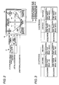
- the yawing motion control map 44 of the present embodiment is composed of a plurality of maps.
- Fig. 4A is a basic map.
- Fig. 4B is a map selected at the time of accelerating the vehicle.
- Fig. 4C is a map selected at the time of decelerating the vehicle.
- Fig. 4D is a map selected at the time of high speed running of the vehicle.
- Fig. 4E is a map selected at the time of low speed running of the vehicle.
- a basic arrangement of the map is explained below referring to Fig. 4A which represents the above maps.
- the axis of abscissas prescribes a degree of under-steering (US) generated in the vehicle 1 which is found from a turning state of the vehicle 1, that is, which is found from the control yaw moment obtained by the control yaw moment calculation portion 41 and from the result of the judgment made by US/OS judging portion 42.
- the axis of abscissas prescribes a degree of over-steering (OS).
- the axis of ordinate prescribes an absolute value of the control value for the rear differential gear controller 31 and the braking device controller 33.
- the high speed means a speed that is no less than a prescribed value
- the low speed means a speed that is less than the prescribed value.
- the yawing motion control map 44 mainly prescribes an over-steering suppression region 44A and an under-steering suppression region 44B.
- the rear differential control region 44A1 and the braking control region 44A2 are prescribed in the order of the control yaw moment, wherein the lowest control yaw moment is arranged first.
- the under-steering suppression region 44B the rear differential control region 44B1 and the braking control region 44B2 are prescribed in the order of the control yaw moment in which the lowest control yaw moment is arranged first.
- the yawing motion control portion 43 controls the rear differential gear controller 31 so that a drive force of the wheel (inner turning wheel), which is a wheel in the right wheel 14R and the left wheel 14L located on the turning center side, can be increased.
- the yawing motion control portion 43 controls the braking device controller 33 so that the braking force of the outer turning wheel can be stronger than the braking force of the inner turning wheel.
- the yawing motion control portion 43 controls the rear differential gear controller 31 so that a drive force of the wheel (turning outer wheel) on the opposite side to the inner turning wheel in the right wheel 14R and the left wheel 14L can be increased.
- the yawing motion control portion 43 controls the braking device controller 33 so that the braking force of the inner turning wheel can be stronger than the braking force of the outer turning wheel.
- the yawing motion control portion 43 distributes an amount of control to the rear differential gear controller 31 and the braking device controller 33 and while the rear differential gear controller 31 is being controlled so that a drive force of the inner turning wheel can be increased, the braking device controller 33 is controlled so that a braking force of the outer turning wheel can be increased.
- the yawing motion control portion 43 distributes an amount of control to the rear differential gear controller 31 and the braking device controller 33 and while the rear differential gear controller 31 is being controlled so that a drive force of the outer turning wheel can be increased, the braking device controller 33 is controlled so that a braking force of the inner turning wheel can be increased.
- a ratio of the amount of control to be distributed to the rear differential controller 31 is made to be higher than the ratio of the amount of control to be distributed in the case where the yawing motion of the vehicle is suppressed (at the time of the generation of OS).
- a ratio of the amount of control to be distributed to the braking device controller 33 is made to be higher than the ratio of the amount of control to be distributed in the case where the yawing motion of the vehicle is facilitated (at the time of the generation of US).
- the yawing motion control map 44 having the above control characteristic is provided.
- the basic control characteristic in the case of using the yawing motion control map 44 is described above.
- the yawing motion map 44 is set in detail not only for the case of under-steering (US) and over-steering (OS) but also for the case in which an absolute value of controlling is controlled being changed according to the acceleration, deceleration and speed of the vehicle and an amount of the distribution of the control between the drive force moving mechanism 15 for moving a drive force between the right and the left wheel and the braking unit is controlled being changed as shown in Figs. 3 and 4A to 4E . That is, a distribution of the amount of control between the rear differential controller 31 and the braking unit controller 33 can be changed according to the acceleration, deceleration and speed of the vehicle.
- the characteristic of the distribution of the amount of control is previously set according to the yawing motion control map 44 shown in Figs. 4A to 4E .
- the yawing motion control map 44 makes a ratio of the amount of control distributed to the rear differential controller 31 to be higher than a ratio in the case of deceleration (shown in Fig. 4C ). In the case where the result of the detection made by G sensor 49 is a deceleration (shown in Fig. 4C ), the yawing motion control map 44 makes a ratio of the amount of control distributed to the braking unit controller 33 to be higher than a ratio in the case of acceleration (shown in Fig. 4B ).
- a ratio of the amount of control distributed to the rear differential controller 31 is made to be higher than the ratio in the case of a high speed (shown in Fig. 4D ).
- a ratio of the amount of control distributed to the braking unit controller 33 is made to be higher than the ratio in the case of a low speed (shown in Fig. 4E ) .
- the characteristic is set as described above. The characteristic of the intensity of the amount of control is shown in Fig. 3 .
- the rear differential gear shows a rear differential controller 31 (drive force moving mechanism 15 for moving a drive force between the right and the left wheel).
- the brake shows a braking unit controller 33 (braking device 21L, 21R, 22L, 22R).
- "High”, “Middle” and “Low” are heights of the absolute values of the devices, that is, “High”, “Middle” and “Low” are values of the hydraulic pressure of the devices. These values are previously stored in ECU 40.
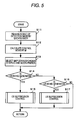
- the turning behavior control device of a vehicle of the embodiment of the present invention is composed as described above. Therefore, it exhibits the following action and effect. Contents of the action and effect will be explained referring to the flow charts shown in Figs. 5 to 7 .
- step S11 the control yaw moment calculating portion 41 reads in a steering angle detected by the steering sensor 47, a vehicle speed detected by each vehicle speed sensor 45 and an actual yaw rate detected by the yaw rate sensor 48.
- US/OS judging portion 42 reads in a lateral acceleration detected by G sensor 49.
- step S12 the control yaw moment calculating portion 41 calculates a target yaw rate according to the steering angle and the vehicle speed that was read in before. When the target yaw rate and the actual yaw rate are compared with each other, the control yaw moment calculating portion 41 calculates a control yaw moment. After that, in step S13, a map (shown in Figs. 4A to 4E ) corresponding to the speed and the acceleration and deceleration is selected.
- step S14 and S16 according to the control yaw moment and the lateral acceleration, US/OS judging portion 42 judges whether over-steering (OS) is generated in the vehicle 1, under-steering (US) is generated in the vehicle 1 or neither under-steering (US) nor over-steering (OS) is substantially generated.
- the program proceeds to step S15 and OS suppression control, which is a sub-routine, is carried out.
- OS suppression control which is a sub-routine
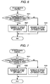
- OS suppression control and US suppression control which are sub-routines, will be explained below.
- OS suppression control shown in Fig. 6 when torque moving control (rear differential gear control) made between the right rear wheel 14R and the left rear wheel 14L by the rear differential gear controller 31 is carried out by the rear differential gear controller 31 in step S21, it is judged whether or not the control yaw moment can be satisfied.
- step S22 when it is judged that the control yaw moment can be satisfied by carrying out the rear differential gear control, in step S22, the rear differential control is carried out according to the characteristic of the selected map. Due to the foregoing, a difference in torque between the right rear wheel 14R and the left rear wheel 14L is adjusted, so that over-steering generated in the vehicle 1 can be suppressed.
- step S23 in addition to the rear differential gear control corresponding to the characteristic of the selected map, the control (the brake control) executed by the braking device controller 33, in which the braking force given to the outer turning wheel is made to be stronger than the braking force given to the inner turning wheel, is carried out. Due to the foregoing, over-steering generated in the wheel 1 is suppressed.
- step S31 when the rear differential gear control is carried out, it is judged whether or not the control yaw moment can be satisfied. In this case, when it has been judged that the control yaw moment can be satisfied by carrying out the rear differential gear control, in step S32, the rear differential gear control is carried out corresponding to the characteristic of the selected map, so that a difference of torque between the right rear wheel 14R and the left rear wheel 14L can be adjusted. In this way, under-steering generated in the vehicle 1 is suppressed.
- step S33 in addition to the rear differential gear control, the braking control is carried out corresponding to the characteristic of the selected map, so that under-steering generated in the vehicle 1 can be suppressed.
- a drive force of the inner turning wheel is increased and a braking force of the outer turning wheel is increased.
- a drive force of the outer turning wheel is increased and a braking force of the inner turning wheel is increased. Accordingly, the turning performance of the vehicle can be enhanced.
- an amount of the distribution of the control between the rear differential gear controller 31 and the braking device controller 33 is controlled being changed. Therefore, as compared with a case in which the amount of the distribution of the control is fixed, it is possible for the case of the present embodiment can flexibly cope with a state of the vehicle. Accordingly, a drive feeling can be enhanced.
- a ratio of the amount of the control distributed to the rear differential gear controller 31 is made to be higher than the ratio in the case of suppressing the yawing motion of the vehicle (at the time of the generation of OS). Therefore, a drive force of the outer turning wheel, the ground contact load of which is heavy, is increased so that the yawing motion control can be effectively executed.
- a ratio of the amount of the control distributed to the braking unit controller 33 is made to be higher than the ratio in the case of facilitating the yawing motion of the vehicle 1 (at the time of the generation of US) . Therefore, a drive force of the outer turning wheel, the ground contact load of which is heavy, is increased so that the yawing motion control can be effectively executed and the turning performance can be stabilized.
- a ratio of the amount of the control distributed to the rear differential controller 31 is made to be higher than the ratio of the case of deceleration shown in Fig. 4C . Therefore, at the time of acceleration in which a ground contact load of the wheel is increased, the drive force is more increased so that the yawing motion control can be more effectively executed. Accordingly, while a feeling of deceleration at the time of acceleration is being decreased, the turning performance can be stabilized and the drive feeling can be more enhanced.
- the map shown in Fig. 4C is selected in step S13 shown in Fig.
- a ratio of the amount of the control distributed to the controller 33 of the braking unit is made to be higher than the ratio in the case of acceleration shown in Fig. 4C . Therefore, even when the wheel load is reduced due to deceleration, a decrease in the lateral force of the wheel caused by an increase in the difference of the drive force between the right wheel and the left wheel can be suppressed. Accordingly, the turning performance at the time of deceleration can be stabilized.
- a ratio of the amount of the control distributed to the rear differential controller 31 is made to be higher than the ratio of the case of a high speed shown in Fig. 4D .
- a ratio of the amount of the control distributed to the controller 33 of the braking unit is made to be higher than the ratio of the case of a low speed shown in Fig. 4E . Therefore, while a feeling of deceleration caused by in increase in an excessively strong braking force is being suppressed, under-steering and over-steering can be properly suppressed and the turning performance of the vehicle can be enhanced.
- the front differential gear 6 is a torque induction type differential gear which mechanically restricts a differential motion made between the right 8R and the left wheel 8L according to an intensity of torque inputted from the engine 2.
- the present invention is not limited to the above specific embodiment.
- the drive force moving mechanism 15 for moving a drive force between the right and the left wheel may be arranged not only in the rear differential gear 12 but also in the front differential gear 6.
- the drive force moving mechanism 15 for moving a drive force between the right and the left wheel may be arranged only in the front differential gear 6.
- the vehicle 1 is a four-wheel drive vehicle.
- the vehicle 1 is not especially limited to a four-wheel-drive vehicle.
- the vehicle 1 may be a front-wheel drive vehicle.
- the vehicle 1 may be a rear-wheel drive vehicle.
- a mechanism of distributing a drive force between the right and the left wheel may be used.
- the following constitution may be adopted.
- clutch mechanisms are respectively arranged in the right and the left wheel and fastening forces of these clutch mechanisms are adjusted, intensities of the drive forces transmitted to the right and the left wheel may be changed. Further, this constitution may be applied to the rear wheel side or the front wheel side.
- a judgment of under-steering/over-steering is made according to the control yaw moment obtained by the control yaw moment calculating portion 41 and according to the acceleration in the lateral direction of the vehicle 1 measured by G sensor 49.
- the present invention is not limited to the above specific embodiment. As long as it is possible to judge a turning state of the vehicle, any structure may be adopted.
- the speed information is detected by the vehicle speed sensors 45L, 45R, 46L, 46R.
- the present invention is not limited to the above specific embodiment.
- the following constitution may be adopted.
- Low-speed-corner/high-speed-corner is estimated from the detection information sent from the steering wheel angle sensor 47 and a map is selected according to the thus estimated value.
- an acceleration of the vehicle in the longitudinal direction is detected by G sensor 49.
- the present invention is not limited to the above specific embodiment.
- a longitudinal acceleration is estimated and a map may be selected from this estimated value.
- a longitudinal acceleration is estimated from an output torque of the engine 2
- a total reduction ratio of the transmission 3 and a braking torque of the braking unit 21L, 21R, 22L, 22R a map may be selected according to thus estimated value.
- the differential limiting mechanism 19 for limiting a differential between a front and a rear wheel is of the gear type.
- the present invention is not limited to the above specific embodiment. As long as it has the same function, any type differential limiting mechanism may be used.
Landscapes
- Engineering & Computer Science (AREA)
- Transportation (AREA)
- Mechanical Engineering (AREA)
- Automation & Control Theory (AREA)
- Physics & Mathematics (AREA)
- Mathematical Physics (AREA)
- Regulating Braking Force (AREA)
- Retarders (AREA)
- Arrangement And Driving Of Transmission Devices (AREA)
- Control Of Driving Devices And Active Controlling Of Vehicle (AREA)
- Non-Deflectable Wheels, Steering Of Trailers, Or Other Steering (AREA)
- Hydraulic Control Valves For Brake Systems (AREA)
Applications Claiming Priority (1)
| Application Number | Priority Date | Filing Date | Title |
|---|---|---|---|
| JP2007179646A JP4179392B1 (ja) | 2007-07-09 | 2007-07-09 | 車両の旋回挙動制御装置 |
Publications (3)
| Publication Number | Publication Date |
|---|---|
| EP2014530A2 true EP2014530A2 (de) | 2009-01-14 |
| EP2014530A3 EP2014530A3 (de) | 2009-01-28 |
| EP2014530B1 EP2014530B1 (de) | 2015-05-13 |
Family
ID=39870146
Family Applications (1)
| Application Number | Title | Priority Date | Filing Date |
|---|---|---|---|
| EP20080153158 Ceased EP2014530B1 (de) | 2007-07-09 | 2008-03-20 | Vorrichtung für die Kurven-Regelung eines Fahrzeugs |
Country Status (6)
| Country | Link |
|---|---|
| US (1) | US7761215B2 (de) |
| EP (1) | EP2014530B1 (de) |
| JP (1) | JP4179392B1 (de) |
| KR (1) | KR100905190B1 (de) |
| CN (1) | CN101342904B (de) |
| RU (1) | RU2388631C2 (de) |
Cited By (2)
| Publication number | Priority date | Publication date | Assignee | Title |
|---|---|---|---|---|
| RU2674643C1 (ru) * | 2016-09-12 | 2018-12-11 | Тойота Дзидося Кабусики Кайся | Устройство управления транспортным средством |
| EP3372463A4 (de) * | 2015-11-06 | 2019-12-25 | Advics Co., Ltd. | Fahrassistenzsystem für ein fahrzeug |
Families Citing this family (18)
| Publication number | Priority date | Publication date | Assignee | Title |
|---|---|---|---|---|
| DE102006031511A1 (de) * | 2006-07-07 | 2008-01-17 | Robert Bosch Gmbh | Verfahren zum Kompensieren der Bremsverzögerung bei einer Fahrzeugregelung |
| JP4313828B2 (ja) * | 2007-05-31 | 2009-08-12 | 三菱自動車工業株式会社 | 左右駆動力配分装置 |
| JP4179391B1 (ja) | 2007-07-09 | 2008-11-12 | 三菱自動車工業株式会社 | 車両の旋回挙動制御装置 |
| JP5138624B2 (ja) * | 2009-03-18 | 2013-02-06 | 日立オートモティブシステムズ株式会社 | 車両挙動制御装置 |
| DE102010027978A1 (de) * | 2010-04-20 | 2011-10-20 | Robert Bosch Gmbh | Fahrerassistenzsystem und Verfahren zur Einstellung eines Fahrerassistenzsystems |
| GB2531941B (en) | 2010-09-14 | 2016-06-15 | Abu Al-Rubb Khalil | Electro-mechanical interface |
| JP5810692B2 (ja) * | 2011-07-08 | 2015-11-11 | 三菱自動車工業株式会社 | 車両旋回挙動制御装置 |
| JP5912505B2 (ja) * | 2011-12-20 | 2016-04-27 | トヨタ自動車株式会社 | 車両走行支援装置 |
| JP5917906B2 (ja) * | 2011-12-20 | 2016-05-18 | トヨタ自動車株式会社 | 車両走行支援装置 |
| JP5970322B2 (ja) * | 2012-10-01 | 2016-08-17 | 日立オートモティブシステムズ株式会社 | 車両の運動制御装置 |
| US9376101B2 (en) * | 2013-08-28 | 2016-06-28 | Continental Automotive Systems, Inc. | All-wheel drive torque vectoring by electronic brake system control |
| WO2017044757A1 (en) * | 2015-09-13 | 2017-03-16 | Gm Global Technology Operations, Llc | Automotive vehicle actuator control system |
| JP6648495B2 (ja) * | 2015-11-10 | 2020-02-14 | アイシン精機株式会社 | 車両用駆動装置 |
| CN108116270B (zh) * | 2016-11-30 | 2020-07-10 | 比亚迪股份有限公司 | 车辆失稳控制方法、车辆失稳控制装置和车辆 |
| JP6790971B2 (ja) * | 2017-04-03 | 2020-11-25 | トヨタ自動車株式会社 | 車両のブレーキ装置 |
| JP6969440B2 (ja) * | 2018-02-26 | 2021-11-24 | トヨタ自動車株式会社 | 車両の運転支援装置 |
| KR102659235B1 (ko) * | 2019-04-11 | 2024-04-19 | 현대자동차주식회사 | 전자식 차동제한장치의 제어방법 |
| JP7215391B2 (ja) * | 2019-10-15 | 2023-01-31 | トヨタ自動車株式会社 | 自動運転車両の車両制御システム及び車両制御装置 |
Citations (1)
| Publication number | Priority date | Publication date | Assignee | Title |
|---|---|---|---|---|
| US6076033A (en) | 1995-09-26 | 2000-06-13 | Honda Giken Kogyo Kabushiki Kaisha | Process for controlling yaw moment in vehicle |
Family Cites Families (25)
| Publication number | Priority date | Publication date | Assignee | Title |
|---|---|---|---|---|
| JP2623905B2 (ja) * | 1990-04-20 | 1997-06-25 | 日産自動車株式会社 | 車両用駆動系クラッチ制御装置 |
| JP2853474B2 (ja) * | 1992-08-24 | 1999-02-03 | トヨタ自動車株式会社 | 四輪駆動車の駆動力配分装置 |
| US5541840A (en) * | 1993-06-25 | 1996-07-30 | Chrysler Corporation | Hand held automotive diagnostic service tool |
| JPH07101262A (ja) * | 1993-10-04 | 1995-04-18 | Nissan Motor Co Ltd | トルク配分制御装置 |
| JP3274758B2 (ja) | 1993-12-17 | 2002-04-15 | マツダ株式会社 | 自動車の駆動力配分制御装置 |
| JP3303605B2 (ja) * | 1995-05-17 | 2002-07-22 | トヨタ自動車株式会社 | 車輌の挙動制御装置 |
| JP3183124B2 (ja) * | 1995-09-28 | 2001-07-03 | 三菱自動車工業株式会社 | 車両の旋回挙動制御装置 |
| DE69724383T2 (de) * | 1996-11-13 | 2004-06-24 | Honda Giken Kogyo K.K. | System zur Kontrolle des Giermomentes in Fahrzeugen |
| US6035251A (en) * | 1997-11-10 | 2000-03-07 | General Motors Corporation | Brake system control method employing yaw rate and ship angle control |
| JP4119020B2 (ja) * | 1998-10-28 | 2008-07-16 | 本田技研工業株式会社 | 車両制御装置 |
| JP4071400B2 (ja) * | 1999-09-07 | 2008-04-02 | 本田技研工業株式会社 | 車両の協調制御装置 |
| RU2212348C2 (ru) * | 2000-08-15 | 2003-09-20 | Военный автомобильный институт | Способ регулирования тормозных сил при торможении на повороте |
| JP2004075013A (ja) | 2002-08-22 | 2004-03-11 | Denso Corp | 車両制御装置 |
| JP3870911B2 (ja) * | 2003-02-10 | 2007-01-24 | 日産自動車株式会社 | 車線逸脱防止装置 |
| JP2005047437A (ja) * | 2003-07-30 | 2005-02-24 | Advics:Kk | 車両の運動制御装置 |
| JP2005104346A (ja) * | 2003-09-30 | 2005-04-21 | Mitsubishi Fuso Truck & Bus Corp | 車両のスタビリティファクタ学習方法及び学習装置並びに車両用制御装置 |
| JP4391304B2 (ja) * | 2004-04-23 | 2009-12-24 | 日産自動車株式会社 | 減速制御装置 |
| JP4114657B2 (ja) * | 2004-10-25 | 2008-07-09 | 三菱自動車工業株式会社 | 車両の旋回挙動制御装置 |
| JP4615321B2 (ja) * | 2005-01-26 | 2011-01-19 | 富士重工業株式会社 | 4輪駆動車の制御装置 |
| JP4131269B2 (ja) * | 2005-03-01 | 2008-08-13 | トヨタ自動車株式会社 | 車輌の制駆動力制御装置 |
| JP4618105B2 (ja) * | 2005-11-11 | 2011-01-26 | 三菱自動車工業株式会社 | 車両の旋回挙動制御装置 |
| DE102005058945A1 (de) * | 2005-12-09 | 2007-06-14 | Zf Friedrichshafen Ag | Verfahren zum Betreiben eines Antriebsstranges eines Fahrzeugs |
| RU54344U1 (ru) * | 2005-12-16 | 2006-06-27 | Общество с ограниченной ответственностью "Старт"-ООО "Старт" | Антиблокировочное устройство транспортного средства с превентивным регулированием его курсовой устойчивости на криволинейной траектории |
| JP2010516556A (ja) * | 2007-01-25 | 2010-05-20 | 本田技研工業株式会社 | 車両の安定性を改善するための車両システムの制御方法 |
| JP4179391B1 (ja) * | 2007-07-09 | 2008-11-12 | 三菱自動車工業株式会社 | 車両の旋回挙動制御装置 |
-
2007
- 2007-07-09 JP JP2007179646A patent/JP4179392B1/ja not_active Expired - Fee Related
-
2008
- 2008-02-18 KR KR1020080014346A patent/KR100905190B1/ko not_active Expired - Fee Related
- 2008-03-19 US US12/051,577 patent/US7761215B2/en active Active
- 2008-03-19 RU RU2008110647/11A patent/RU2388631C2/ru active
- 2008-03-20 CN CN2008100871685A patent/CN101342904B/zh not_active Expired - Fee Related
- 2008-03-20 EP EP20080153158 patent/EP2014530B1/de not_active Ceased
Patent Citations (1)
| Publication number | Priority date | Publication date | Assignee | Title |
|---|---|---|---|---|
| US6076033A (en) | 1995-09-26 | 2000-06-13 | Honda Giken Kogyo Kabushiki Kaisha | Process for controlling yaw moment in vehicle |
Cited By (2)
| Publication number | Priority date | Publication date | Assignee | Title |
|---|---|---|---|---|
| EP3372463A4 (de) * | 2015-11-06 | 2019-12-25 | Advics Co., Ltd. | Fahrassistenzsystem für ein fahrzeug |
| RU2674643C1 (ru) * | 2016-09-12 | 2018-12-11 | Тойота Дзидося Кабусики Кайся | Устройство управления транспортным средством |
Also Published As
| Publication number | Publication date |
|---|---|
| US7761215B2 (en) | 2010-07-20 |
| JP4179392B1 (ja) | 2008-11-12 |
| KR100905190B1 (ko) | 2009-06-29 |
| EP2014530B1 (de) | 2015-05-13 |
| CN101342904B (zh) | 2012-11-28 |
| US20090018741A1 (en) | 2009-01-15 |
| EP2014530A3 (de) | 2009-01-28 |
| JP2009012708A (ja) | 2009-01-22 |
| CN101342904A (zh) | 2009-01-14 |
| RU2008110647A (ru) | 2009-09-27 |
| KR20090005949A (ko) | 2009-01-14 |
| RU2388631C2 (ru) | 2010-05-10 |
Similar Documents
| Publication | Publication Date | Title |
|---|---|---|
| EP2014530B1 (de) | Vorrichtung für die Kurven-Regelung eines Fahrzeugs | |
| EP2014527B1 (de) | Kurven-Regelvorrichtung für ein Kraftfahrzeug | |
| US7073621B2 (en) | Vehicle steering control device | |
| EP2181026B1 (de) | Vorrichtung zur steuerung des fahrzeugverhaltens | |
| CN101070068B (zh) | 车辆转向控制装置 | |
| JP4618105B2 (ja) | 車両の旋回挙動制御装置 | |
| KR100918163B1 (ko) | 구동력 배분 제어 장치 | |
| JP4289243B2 (ja) | 車両用左右輪間駆動力制御装置 | |
| KR102881929B1 (ko) | 차량의 자세 제어 방법 | |
| CN103118911B (zh) | 车辆行驶控制装置 | |
| CN107848509B (zh) | 用于在路面上积水打滑时辅助驾驶员的方法 | |
| EP2055599B1 (de) | Vorrichtung zur Steuerung des Fahrzeugverhaltens | |
| US20040064239A1 (en) | Power distribution control apparatus for four wheel drive vehicle | |
| JP2013018326A (ja) | 車両旋回挙動制御装置 | |
| JP2012035698A (ja) | 車両の制動制御装置 | |
| EP2289746B1 (de) | System zur Verbesserung der Kurvenfahrtleistung eines Fahrzeugs, das von einem Sicherheitssystem gesteuert wird | |
| JP3413996B2 (ja) | ヨーイング運動量制御装置を備えた車両のアンチスキッド制御装置 | |
| JP5040013B2 (ja) | 車両の旋回挙動制御装置 | |
| JP4993105B2 (ja) | 車両の挙動制御装置 | |
| JP2009056919A (ja) | 車両の駆動力制御装置 | |
| JPH05319125A (ja) | 4輪駆動車の走行制御装置 |
Legal Events
| Date | Code | Title | Description |
|---|---|---|---|
| PUAI | Public reference made under article 153(3) epc to a published international application that has entered the european phase |
Free format text: ORIGINAL CODE: 0009012 |
|
| PUAL | Search report despatched |
Free format text: ORIGINAL CODE: 0009013 |
|
| 17P | Request for examination filed |
Effective date: 20080320 |
|
| AK | Designated contracting states |
Kind code of ref document: A2 Designated state(s): AT BE BG CH CY CZ DE DK EE ES FI FR GB GR HR HU IE IS IT LI LT LU LV MC MT NL NO PL PT RO SE SI SK TR |
|
| AX | Request for extension of the european patent |
Extension state: AL BA MK RS |
|
| AK | Designated contracting states |
Kind code of ref document: A3 Designated state(s): AT BE BG CH CY CZ DE DK EE ES FI FR GB GR HR HU IE IS IT LI LT LU LV MC MT NL NO PL PT RO SE SI SK TR |
|
| AX | Request for extension of the european patent |
Extension state: AL BA MK RS |
|
| RIC1 | Information provided on ipc code assigned before grant |
Ipc: B60T 8/1755 20060101ALN20081219BHEP Ipc: B60W 10/12 20060101ALN20081219BHEP Ipc: B62D 37/00 20060101ALI20081219BHEP Ipc: B60T 8/60 20060101ALI20081219BHEP Ipc: B60W 30/02 20060101AFI20081030BHEP Ipc: B60W 10/18 20060101ALN20081219BHEP |
|
| AKX | Designation fees paid |
Designated state(s): DE FR |
|
| 17Q | First examination report despatched |
Effective date: 20100422 |
|
| RIC1 | Information provided on ipc code assigned before grant |
Ipc: B60W 10/04 20060101ALI20140924BHEP Ipc: B60W 10/12 20120101ALN20140924BHEP Ipc: B60W 10/18 20120101ALN20140924BHEP Ipc: B60W 30/045 20120101ALI20140924BHEP Ipc: B60T 8/32 20060101ALI20140924BHEP Ipc: B60T 8/24 20060101ALI20140924BHEP Ipc: B60W 30/02 20120101AFI20140924BHEP Ipc: B62D 37/00 20060101ALI20140924BHEP Ipc: B60T 8/1755 20060101ALN20140924BHEP |
|
| GRAP | Despatch of communication of intention to grant a patent |
Free format text: ORIGINAL CODE: EPIDOSNIGR1 |
|
| INTG | Intention to grant announced |
Effective date: 20141030 |
|
| RIC1 | Information provided on ipc code assigned before grant |
Ipc: B60W 10/12 20120101ALN20141021BHEP Ipc: B60W 30/045 20120101ALI20141021BHEP Ipc: B60W 10/18 20120101ALN20141021BHEP Ipc: B60T 8/24 20060101ALI20141021BHEP Ipc: B60T 8/1755 20060101ALN20141021BHEP Ipc: B60T 8/32 20060101ALI20141021BHEP Ipc: B62D 37/00 20060101ALI20141021BHEP Ipc: B60W 30/02 20120101AFI20141021BHEP Ipc: B60W 10/04 20060101ALI20141021BHEP |
|
| RIN1 | Information on inventor provided before grant (corrected) |
Inventor name: USHIRODA, YUICHI Inventor name: TAKAHASHI, NAOKI Inventor name: SUZUKI, KEIJI Inventor name: MATSUI, TAKAO Inventor name: SAWASE, KAORU Inventor name: MIURA, TAKAMI |
|
| GRAS | Grant fee paid |
Free format text: ORIGINAL CODE: EPIDOSNIGR3 |
|
| GRAA | (expected) grant |
Free format text: ORIGINAL CODE: 0009210 |
|
| AK | Designated contracting states |
Kind code of ref document: B1 Designated state(s): DE FR |
|
| REG | Reference to a national code |
Ref country code: DE Ref legal event code: R096 Ref document number: 602008038123 Country of ref document: DE Effective date: 20150625 |
|
| REG | Reference to a national code |
Ref country code: FR Ref legal event code: PLFP Year of fee payment: 9 |
|
| REG | Reference to a national code |
Ref country code: DE Ref legal event code: R097 Ref document number: 602008038123 Country of ref document: DE |
|
| PLBE | No opposition filed within time limit |
Free format text: ORIGINAL CODE: 0009261 |
|
| STAA | Information on the status of an ep patent application or granted ep patent |
Free format text: STATUS: NO OPPOSITION FILED WITHIN TIME LIMIT |
|
| 26N | No opposition filed |
Effective date: 20160216 |
|
| REG | Reference to a national code |
Ref country code: FR Ref legal event code: PLFP Year of fee payment: 10 |
|
| REG | Reference to a national code |
Ref country code: FR Ref legal event code: PLFP Year of fee payment: 11 |
|
| PGFP | Annual fee paid to national office [announced via postgrant information from national office to epo] |
Ref country code: DE Payment date: 20240130 Year of fee payment: 17 |
|
| PGFP | Annual fee paid to national office [announced via postgrant information from national office to epo] |
Ref country code: FR Payment date: 20240213 Year of fee payment: 17 |
|
| REG | Reference to a national code |
Ref country code: DE Ref legal event code: R119 Ref document number: 602008038123 Country of ref document: DE |
|
| PG25 | Lapsed in a contracting state [announced via postgrant information from national office to epo] |
Ref country code: DE Free format text: LAPSE BECAUSE OF NON-PAYMENT OF DUE FEES Effective date: 20251001 |
|
| PG25 | Lapsed in a contracting state [announced via postgrant information from national office to epo] |
Ref country code: FR Free format text: LAPSE BECAUSE OF NON-PAYMENT OF DUE FEES Effective date: 20250331 |