EP2013568B1 - Horizontalarm-koordinatenmessmaschine - Google Patents
Horizontalarm-koordinatenmessmaschine Download PDFInfo
- Publication number
- EP2013568B1 EP2013568B1 EP06745262A EP06745262A EP2013568B1 EP 2013568 B1 EP2013568 B1 EP 2013568B1 EP 06745262 A EP06745262 A EP 06745262A EP 06745262 A EP06745262 A EP 06745262A EP 2013568 B1 EP2013568 B1 EP 2013568B1
- Authority
- EP
- European Patent Office
- Prior art keywords
- base
- axis
- carriage
- upright
- machine according
- Prior art date
- Legal status (The legal status is an assumption and is not a legal conclusion. Google has not performed a legal analysis and makes no representation as to the accuracy of the status listed.)
- Expired - Lifetime
Links
Images

Classifications
-
- G—PHYSICS
- G01—MEASURING; TESTING
- G01B—MEASURING LENGTH, THICKNESS OR SIMILAR LINEAR DIMENSIONS; MEASURING ANGLES; MEASURING AREAS; MEASURING IRREGULARITIES OF SURFACES OR CONTOURS
- G01B5/00—Measuring arrangements characterised by the use of mechanical techniques
- G01B5/004—Measuring arrangements characterised by the use of mechanical techniques for measuring coordinates of points
- G01B5/008—Measuring arrangements characterised by the use of mechanical techniques for measuring coordinates of points using coordinate measuring machines
Definitions
- the present invention relates to a coordinate measuring machine of the horizontal-arm type.
- Coordinate measuring machines of the aforesaid type comprising a base provided with guides along a first horizontal axis X, a first carriage mobile on the base along the axis X and comprising an upright provided with guides extending along a second vertical axis Z, a second carriage carried by the upright and sliding on the same along axis Z, and an arm carried by the second carriage and extending along a third horizontal axis Y orthogonal to the axis X.
- One end of the arm is adapted to carry a contact or optical detector for measuring the dimensional features of parts.
- Machines of this type may be used, for example, in the automotive industry, individually or in pairs, for dimensional monitoring of vehicle bodyworks on manufacturing lines; such machines are therefore large in size.
- the measuring volume may be in the order of 6-7 m along axis X, 1.5-2 m along axis Y, and 2-3 m along axis Z.
- the coordinate machines of the type briefly described must be assembled and tested at the manufacturing plant, and therefore disassembled again, at least partially, to be transported to the installation plant. It is indeed unthinkable, given the dimensions of the concerned machines, to deliver them assembled.
- a coordinate measuring machine with articulated connection means is disclosed in GB-2191000 .
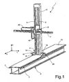
- figure 1 it is indicated as a whole by 1a horizontal-arm coordinate measuring machine.
- Machine 1 essentially comprises a base 2 provided with guides 3 along a horizontal axis X, a first carriage 4 mobile on the base 2 along the axis X and provided with guides 5 extending along a vertical axis Z, a second carriage 6 carried by the first carriage 4 and sliding along the axis Z, and a horizontal arm 7 carried by the second carriage 6, extending along a axis Y orthogonal to the axis X and axially mobile along the axis Y.
- One end of the arm 7 is adapted to carry a contact or optical detector (not shown) for measuring dimensional features of parts.
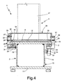
- base 2 ( figure 4 ) essentially consists of a box-type structure 10 elongated in the direction of the axis X, with constant section, having a flat horizontal bottom wall 11 and top wall 12, and a pair of vertical, reciprocally parallel side walls 13, 14.
- the side walls 13, 14 are reciprocally spaced at a distance smaller than the width of the walls 11, 12 so that these laterally protrude from the side walls 13, 14 with respective side wings 15.
- the sliding guides 3 for the first carriage 4 along the axis X are fixed under the side wings 15 of the top wall 12, which therefore presents a flat treadable upper surface, being free from guides and delicate components.
- the first carriage 4 comprises a lower base 16 mobile on the guides 3 and an upright 17 having a vertical axis tubular structure which extends upwards from the base 16 and carries the guides 5 for carriage 6.
- the base 16 consists of a central body 18 rigidly fastened to the upright 17 and a pair of side shoulders 19, 20 fixed to opposite sides of the central body 18 and each sliding along a respective guide 3.
- Each of the shoulders presents an essentially L-shaped section, with a vertical plate portion 22 adapted to be fastened to the central body 18 and a lower horizontal portion 23 extending underneath the respective wing 15.
- Ball circulation runners 24 cooperating with the respective guides 3 are fastened on portions 23, conveniently provided with inclined surfaces defining with the balls an "O"-type contact pattern.
- the contact pattern may be of the "X" type; according to another possible embodiment, the runners 24 may be replaced by runners of the pneumostatic type.
- the shoulder 20 presents longer extension along the axis X and is provided with two runners 24; a single runner is carried by shoulder 19. In this way, three rests and therefore an isostatic constraint system are defined as a whole on the guides 3. Such system is rigid according to all degrees of freedom, except for shifting along the axis X.
- the plate portions 22 of the shoulders 19, 20 are fastened to the central body by means of a plurality of screws 27, 28, in total six arranged on two horizontal rows of three in the example shown. Such screws 27, 28 throughly engage respective holes 29 made in the plate portions 22 and are adapted to be fastened in respective threaded holes 30 of the central body 18.
- the holes 30 on opposite sides of the central body 18 are paired and reciprocally coaxial.
- the mobile parts of the machine are moved, in a per se known way, by means of rack and pinion devices driven by respective electric motors 31, 32, 33.
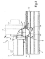
- the first carriage 4 is actuated by an electric motor 31 carried by the shoulder 19 ( fig. 2 ), which provides motion via a belt 35 to a pulley 36 integral with a pinion 37 ( fig. 4 ) which meshes with a rack 38 fastened on the side wall 14 of the base 2 in direction parallel to the axis X.
- the actuating devices of the second carriage 6 and of the arm 7 are similar and are not described in detail.
- connection of the electric motors 31, 32, 33 to the respective power and control system is achieved by means of wirings (not shown) which are housed in articulated chains 40 in the transition zones between relatively moving parts.
- figure 2 clearly shows a chain 40 associated to motor 31, which has one end secured to the base 2 and one end secured to the shoulder 19.
- the upright 17 of the machine 1 machine may be tipped and folded on the base 2 to favour the transportation of the machine 1 from the place of manufacture to the place of installation.
- the upright 17 may be tipped by removing all the screws (27) which connect the central body 18 to the side shoulders 19, 20 except for one screw (28) on each side ( fig. 3 ).
- a bracket 41 ( figure 2 ), fastened in conventional way, for example by means of simple screws, to an upper end of the upright 17, may be fastened to the upper surface 12 of the base, usually provided with holes, so as to lock the upright 17 in the tipped position.
- the horizontal arm 7 is appropriately removed and the second carriage 6 is arranged in its lowest position ( figures 2 and 3 ).
- screws 28 can be replaced by other articulated connection means, so as to allow the upright 17 to be tipped with respect to the shoulders 19, 20.
- Such tipping although preferably consisting of a simple rotation about an axis, may be also defined by a more complex motion.
- Screws 27 may be replaced by any releasable connection means.
- Larger measuring volume in the direction of the axis X may be obtained by joining several bases longitudinally.
Landscapes
- Physics & Mathematics (AREA)
- General Physics & Mathematics (AREA)
- A Measuring Device Byusing Mechanical Method (AREA)
- Length Measuring Devices With Unspecified Measuring Means (AREA)
Claims (11)
- Koordinatenmessmaschine (1) umfasst eine Basis (2), welche mit ersten Führungselementen (3) entlang einer ersten, horizontalen, Achse (X) versehen ist, einem ersten, auf der Basis (2) entlang der ersten Achse (X) beweglichen Träger (4) mit einem Pfosten (17), der mit zweiten Führungselementen (5) versehen ist, die sich entlang einer zweiten, vertikalen Achse (Z) erstrecken, einem zweiten Träger (6), der durch den Pfosten (17) getragen und entlang der zweiten Achse (Z) verschieblich ist, und einem horizontalen Arm (7), der durch den zweiten Träger (6) getragen ist und sich entlang einer dritten, horizontalen, Achse (Y) senkrecht zur ersten Achse (X) erstreckt und beweglich entlang der dritten Achse (Y) ist, dadurch gekennzeichnet, dass der erste Träger (4) eine Basis (16) aufweist, die wenigstens mit einem ersten Bereich (19, 20), der mit der ersten Führungseinrichtung (3) gekuppelt ist, und mit wenigstens einem zweiten Bereich (18), der starr mit dem Pfosten (17) verbunden ist, und mit lösbare Verbindungsmittel (27) zum wechselseitigen Verbinden des ersten Bereichs (19,20) und des zweiten Bereichs der Trägerbasis (16) und einem beweglichen Verbindungsmittel (28) zwischen dem ersten Bereich (19,20) und dem zweiten Bereich (18) der Trägerbasis (16), um dem Pfosten (17) zu ermöglichen, in Bezug auf den ersten Bereich (19,20) geneigt zu werden, wenn die lösbaren Verbindungsmittel (27) gelöst sind.
- Maschine nach Anspruch 1, dadurch gekennzeichnet, dass die beweglichen Verbindungsmittel (28) Gelenkverbindungsmittel sind, die einer Rotationsachse (A) für den zweiten Bereich (18) in Bezug auf den ersten Bereich (19,20) bilden.
- Maschine nach Anspruch 1 oder 2, dadurch gekennzeichnet, dass das erste Führungselement eine Paar von Seitenführungen (3) aufweist, die durch die Basis (2) getragen und parallel zur ersten Achse (X) sind, und dass der zweite Bereich der Basis (16) durch einen zentralen Bereich (18) der Basis (16) definiert ist, der starr mit dem Pfosten (17) verbunden ist, und dass wenigstens der erste Bereich der Basis (16) durch ein Paar von seitlichen Schultern (19,20) definiert ist, die mit der jeweiligen Führung (3) gekuppelt sind.
- Maschine nach Anspruch 3, dadurch gekennzeichnet, dass die lösbaren Verbindungsmittel eine Anzahl von ersten Schrauben (27) aufweisen, die jeweils die erste Schulter (19,20) mit gegenüberliegenden Seiten des zentralen Bereichs (18) verbinden.
- Maschine nach Anspruch 3 oder 4, dadurch gekennzeichnet, dass die Gelenkverbindungsmittel ein Paar von wechselseitig koaxialen Schrauben (28) aufweisen welche jeder der Schulter (19,20) mit gegenüberliegenden Seiten des zentralen Bereichs verbinden.
- Maschine nach einem der Ansprüche 2 bis 5, dadurch gekennzeichnet, dass die Basis (16) Kugelumlaufschienen (24) aufweist, die mit den Führungen (3) gekuppelt sind.
- Maschine nach einem der vorhergehenden Ansprüche, dadurch gekennzeichnet, dass sie Befestigungsmittel (41) umfasst, um den Pfosten auf der Basis (2) in der geneigten Position des Pfostens (17) zu sichern.
- Maschine nach Anspruch 7, dadurch gekennzeichnet, dass die Befestigungsmittel einen Auflagerbock (41) umfassen, welcher an einem oberen Ende des Pfostens (17) und einer oberen Oberfläche (12) der Basis (2) befestigbar ist.
- Maschine nach einem der Ansprüche 3 bis 8, dadurch gekennzeichnet, dass der erste Träger (4), der zweite Träger (6) und der Arm (7) jeweils durch elektrische Motoren (31, 32, 33) betätigt sind, wobei der elektrische Motor (31) den ersten Träger (4) eintreibt, wobei er durch eine Schulter (19) der Schultern (19,20) getragen ist.
- Maschine nach Anspruch 9, dadurch gekennzeichnet, dass sie eine bewegliche Kette (40) zum Schutz der elektrischen Energie- und Kontrollleitung der elektrischen Motoren (31, 32, 33) aufweist, die mit einem Ende der Basis (2) und mit einem Ende an der Schulter (19) befestigt ist.
- Maschine nach einem der vorhergehenden Ansprüche, dadurch gekennzeichnet, dass die Basis (2) eine flache, betretbare Oberwand (12) aufweist und dass die Seitenführungen (3) unterhalb der Oberwand (12) der Basis (2) befestigt sind.
Priority Applications (1)
| Application Number | Priority Date | Filing Date | Title |
|---|---|---|---|
| PL06745262T PL2013568T3 (pl) | 2006-04-06 | 2006-04-06 | Maszyna do mierzenia współrzędnych z poziomym ramieniem |
Applications Claiming Priority (1)
| Application Number | Priority Date | Filing Date | Title |
|---|---|---|---|
| PCT/IT2006/000230 WO2007113879A1 (en) | 2006-04-06 | 2006-04-06 | Horizontal-arm coordinate measuring machine |
Publications (2)
| Publication Number | Publication Date |
|---|---|
| EP2013568A1 EP2013568A1 (de) | 2009-01-14 |
| EP2013568B1 true EP2013568B1 (de) | 2009-07-29 |
Family
ID=37056833
Family Applications (1)
| Application Number | Title | Priority Date | Filing Date |
|---|---|---|---|
| EP06745262A Expired - Lifetime EP2013568B1 (de) | 2006-04-06 | 2006-04-06 | Horizontalarm-koordinatenmessmaschine |
Country Status (9)
| Country | Link |
|---|---|
| US (1) | US8042279B2 (de) |
| EP (1) | EP2013568B1 (de) |
| CN (1) | CN101460807B (de) |
| AT (1) | ATE438077T1 (de) |
| BR (1) | BRPI0621582A2 (de) |
| DE (1) | DE602006008192D1 (de) |
| ES (1) | ES2328736T3 (de) |
| PL (1) | PL2013568T3 (de) |
| WO (1) | WO2007113879A1 (de) |
Families Citing this family (3)
| Publication number | Priority date | Publication date | Assignee | Title |
|---|---|---|---|---|
| EP2013568B1 (de) * | 2006-04-06 | 2009-07-29 | Hexagon Metrology S.p.A. | Horizontalarm-koordinatenmessmaschine |
| ES2525099B1 (es) | 2013-05-16 | 2015-09-18 | Unimetrik, S.A. | Máquina de control numérico desmontable |
| CN113272618B (zh) * | 2020-05-19 | 2023-06-20 | 深圳元戎启行科技有限公司 | 测量距离的装置 |
Family Cites Families (20)
| Publication number | Priority date | Publication date | Assignee | Title |
|---|---|---|---|---|
| IT1190574B (it) * | 1986-05-27 | 1988-02-16 | Dea Spa | Macchina di misura a coordinate |
| DE3920718A1 (de) * | 1989-06-24 | 1991-01-10 | Leitz Wild Gmbh | Feststehendes portal fuer ein praezisions-koordinatenmessgeraet |
| CN1067502A (zh) * | 1992-05-03 | 1992-12-30 | 国营青岛前哨机械厂 | 水平臂式三坐标测量机 |
| US5621978A (en) * | 1993-07-14 | 1997-04-22 | Sarauer; Alan J. | Bar for coordinate measuring machine |
| DE4402061C1 (de) * | 1994-01-25 | 1995-05-11 | Leitz Mestechnik Gmbh | Feststehendes Portal für Präzisions-Koordinatenmeßgeräte |
| JP3126114B2 (ja) * | 1997-11-12 | 2001-01-22 | 株式会社ミツトヨ | 非接触表面粗さ測定装置 |
| US6430828B1 (en) * | 1998-04-17 | 2002-08-13 | Electronic Measuring Devices, Inc. | Coordinate positioning apparatus with indexable stylus, components thereof, and method of using it |
| EP1342051B1 (de) * | 2000-09-28 | 2005-10-19 | Carl Zeiss Industrielle Messtechnik GmbH | Kalibrierung eines messenden sensors auf einem koordinatenmessgerät mit einer kugel, deren mittelpunkt bekannt ist |
| US20030037451A1 (en) * | 2001-08-27 | 2003-02-27 | Sarauer Alan J. | Vehicle frame measuring device |
| CN2527963Y (zh) * | 2002-03-21 | 2002-12-25 | 曲殿光 | 三坐标测量机直线导轨滑块的调节装置 |
| GB0207298D0 (en) * | 2002-03-28 | 2002-05-08 | Renishaw Plc | Apparatus for changing operating modules on a coordinate positioning machine |
| DE10313038B4 (de) * | 2003-03-24 | 2005-02-17 | Klingelnberg Gmbh | Vorrichtung zur Erfassung der Lage eines Tastelements in einem Mehrkoordinatenmessgerät |
| JP4568621B2 (ja) * | 2005-02-28 | 2010-10-27 | 株式会社ミツトヨ | 表面性状測定機の真直度補正方法および表面性状測定機 |
| US7191540B1 (en) * | 2005-10-31 | 2007-03-20 | Mitutoyo Corporation | Work piece holder for surface measuring apparatus |
| BRPI0621566B8 (pt) * | 2006-04-06 | 2019-03-19 | Hexagon Metrology Spa | máquina de medição de coordenada |
| EP2013568B1 (de) * | 2006-04-06 | 2009-07-29 | Hexagon Metrology S.p.A. | Horizontalarm-koordinatenmessmaschine |
| EP2013569B2 (de) * | 2006-04-18 | 2015-07-29 | Hexagon Metrology S.p.A. | Horizontalarm-koordinatenmessmaschine |
| DE102006019382A1 (de) * | 2006-04-24 | 2007-10-25 | Carl Zeiss Industrielle Messtechnik Gmbh | Scanning einer Oberfläche mit einem Koordinatenmessgerät |
| GB0713639D0 (en) * | 2007-07-13 | 2007-08-22 | Renishaw Plc | Error correction |
| DE102007051054A1 (de) * | 2007-10-19 | 2009-04-30 | Carl Zeiss Industrielle Messtechnik Gmbh | Verfahren zum Korrigieren der Messwerte eines Koordinatenmessgeräts und Koordinatenmessgerät |
-
2006
- 2006-04-06 EP EP06745262A patent/EP2013568B1/de not_active Expired - Lifetime
- 2006-04-06 WO PCT/IT2006/000230 patent/WO2007113879A1/en not_active Ceased
- 2006-04-06 US US12/296,060 patent/US8042279B2/en active Active
- 2006-04-06 AT AT06745262T patent/ATE438077T1/de not_active IP Right Cessation
- 2006-04-06 BR BRPI0621582-3A patent/BRPI0621582A2/pt active IP Right Grant
- 2006-04-06 ES ES06745262T patent/ES2328736T3/es not_active Expired - Lifetime
- 2006-04-06 DE DE602006008192T patent/DE602006008192D1/de active Active
- 2006-04-06 PL PL06745262T patent/PL2013568T3/pl unknown
- 2006-04-06 CN CN2006800548753A patent/CN101460807B/zh not_active Expired - Lifetime
Also Published As
| Publication number | Publication date |
|---|---|
| BRPI0621582A2 (pt) | 2011-12-13 |
| ATE438077T1 (de) | 2009-08-15 |
| WO2007113879A1 (en) | 2007-10-11 |
| ES2328736T3 (es) | 2009-11-17 |
| CN101460807A (zh) | 2009-06-17 |
| US8042279B2 (en) | 2011-10-25 |
| EP2013568A1 (de) | 2009-01-14 |
| US20100218393A1 (en) | 2010-09-02 |
| CN101460807B (zh) | 2011-03-30 |
| PL2013568T3 (pl) | 2009-10-30 |
| DE602006008192D1 (de) | 2009-09-10 |
Similar Documents
| Publication | Publication Date | Title |
|---|---|---|
| US6322854B1 (en) | Multiple head dispensing method | |
| CN101505914B (zh) | 可变形的门型作业装置 | |
| KR101155961B1 (ko) | 컨베이어가 1축을 대체한 2축 구동 검사장치 | |
| CN107073670A (zh) | 加工机械的基座构造及构筑加工机械生产线的基座设置方法 | |
| CN108081755B (zh) | 一种喷绘切割组合装置 | |
| US20090084749A1 (en) | Apparatus for handling parts of any kind, in particular for the linear loading and unloading of machines | |
| EP2013568B1 (de) | Horizontalarm-koordinatenmessmaschine | |
| TWI431713B (zh) | Stage device | |
| CN109760168A (zh) | 一种五轴木门加工中心设备 | |
| EP2425943B1 (de) | Eine Bohrmaschine für das Holz mit einem verbesserten Panel Bohraggregat | |
| CN100381034C (zh) | 部件安装装置 | |
| CN117923374A (zh) | 一种用于装配式建筑的吊装装置及其使用方法 | |
| CN101484281A (zh) | 多关节机器人及配线方法 | |
| KR20200026051A (ko) | 스테이지 측정 지그, 도포 장치 및 스테이지 측정 방법 | |
| KR200408958Y1 (ko) | 정션박스 고정용 인장 시험기의 하부지그 구조 | |
| US8091248B2 (en) | Coordinate measuring machine | |
| WO2013008488A1 (ja) | 組立作業用コンベア装置 | |
| US12398001B2 (en) | Device for the transport of ceramic slabs | |
| CN111319063B (zh) | 机器人的制造方法 | |
| CN216793642U (zh) | 一种晶圆的移位装置 | |
| KR100682620B1 (ko) | 산업로봇용 핸들러 | |
| CN222181011U (zh) | 光伏组件移载机 | |
| CN214818562U (zh) | 一种具有稳定夹持功能的abb机器人 | |
| KR102098401B1 (ko) | 탁상 로봇 | |
| KR20120065250A (ko) | 워크 위치결정 장치 및 그것을 이용한 생산 시스템 |
Legal Events
| Date | Code | Title | Description |
|---|---|---|---|
| PUAI | Public reference made under article 153(3) epc to a published international application that has entered the european phase |
Free format text: ORIGINAL CODE: 0009012 |
|
| 17P | Request for examination filed |
Effective date: 20081031 |
|
| AK | Designated contracting states |
Kind code of ref document: A1 Designated state(s): AT BE BG CH CY CZ DE DK EE ES FI FR GB GR HU IE IS IT LI LT LU LV MC NL PL PT RO SE SI SK TR |
|
| AX | Request for extension of the european patent |
Extension state: AL BA HR MK YU |
|
| GRAP | Despatch of communication of intention to grant a patent |
Free format text: ORIGINAL CODE: EPIDOSNIGR1 |
|
| GRAC | Information related to communication of intention to grant a patent modified |
Free format text: ORIGINAL CODE: EPIDOSCIGR1 |
|
| GRAS | Grant fee paid |
Free format text: ORIGINAL CODE: EPIDOSNIGR3 |
|
| GRAA | (expected) grant |
Free format text: ORIGINAL CODE: 0009210 |
|
| AK | Designated contracting states |
Kind code of ref document: B1 Designated state(s): AT BE BG CH CY CZ DE DK EE ES FI FR GB GR HU IE IS IT LI LT LU LV MC NL PL PT RO SE SI SK TR |
|
| REG | Reference to a national code |
Ref country code: GB Ref legal event code: FG4D |
|
| REG | Reference to a national code |
Ref country code: CH Ref legal event code: EP |
|
| REG | Reference to a national code |
Ref country code: IE Ref legal event code: FG4D |
|
| REG | Reference to a national code |
Ref country code: CH Ref legal event code: NV Representative=s name: MOINAS & SAVOYE SA |
|
| REF | Corresponds to: |
Ref document number: 602006008192 Country of ref document: DE Date of ref document: 20090910 Kind code of ref document: P |
|
| REG | Reference to a national code |
Ref country code: PL Ref legal event code: T3 |
|
| REG | Reference to a national code |
Ref country code: ES Ref legal event code: FG2A Ref document number: 2328736 Country of ref document: ES Kind code of ref document: T3 |
|
| PG25 | Lapsed in a contracting state [announced via postgrant information from national office to epo] |
Ref country code: LT Free format text: LAPSE BECAUSE OF FAILURE TO SUBMIT A TRANSLATION OF THE DESCRIPTION OR TO PAY THE FEE WITHIN THE PRESCRIBED TIME-LIMIT Effective date: 20090729 Ref country code: IS Free format text: LAPSE BECAUSE OF FAILURE TO SUBMIT A TRANSLATION OF THE DESCRIPTION OR TO PAY THE FEE WITHIN THE PRESCRIBED TIME-LIMIT Effective date: 20091129 Ref country code: AT Free format text: LAPSE BECAUSE OF FAILURE TO SUBMIT A TRANSLATION OF THE DESCRIPTION OR TO PAY THE FEE WITHIN THE PRESCRIBED TIME-LIMIT Effective date: 20090729 Ref country code: FI Free format text: LAPSE BECAUSE OF FAILURE TO SUBMIT A TRANSLATION OF THE DESCRIPTION OR TO PAY THE FEE WITHIN THE PRESCRIBED TIME-LIMIT Effective date: 20090729 Ref country code: SE Free format text: LAPSE BECAUSE OF FAILURE TO SUBMIT A TRANSLATION OF THE DESCRIPTION OR TO PAY THE FEE WITHIN THE PRESCRIBED TIME-LIMIT Effective date: 20090729 |
|
| PG25 | Lapsed in a contracting state [announced via postgrant information from national office to epo] |
Ref country code: SI Free format text: LAPSE BECAUSE OF FAILURE TO SUBMIT A TRANSLATION OF THE DESCRIPTION OR TO PAY THE FEE WITHIN THE PRESCRIBED TIME-LIMIT Effective date: 20090729 Ref country code: LV Free format text: LAPSE BECAUSE OF FAILURE TO SUBMIT A TRANSLATION OF THE DESCRIPTION OR TO PAY THE FEE WITHIN THE PRESCRIBED TIME-LIMIT Effective date: 20090729 |
|
| PG25 | Lapsed in a contracting state [announced via postgrant information from national office to epo] |
Ref country code: PT Free format text: LAPSE BECAUSE OF FAILURE TO SUBMIT A TRANSLATION OF THE DESCRIPTION OR TO PAY THE FEE WITHIN THE PRESCRIBED TIME-LIMIT Effective date: 20091129 Ref country code: BG Free format text: LAPSE BECAUSE OF FAILURE TO SUBMIT A TRANSLATION OF THE DESCRIPTION OR TO PAY THE FEE WITHIN THE PRESCRIBED TIME-LIMIT Effective date: 20091029 |
|
| PG25 | Lapsed in a contracting state [announced via postgrant information from national office to epo] |
Ref country code: DK Free format text: LAPSE BECAUSE OF FAILURE TO SUBMIT A TRANSLATION OF THE DESCRIPTION OR TO PAY THE FEE WITHIN THE PRESCRIBED TIME-LIMIT Effective date: 20090729 Ref country code: EE Free format text: LAPSE BECAUSE OF FAILURE TO SUBMIT A TRANSLATION OF THE DESCRIPTION OR TO PAY THE FEE WITHIN THE PRESCRIBED TIME-LIMIT Effective date: 20090729 Ref country code: CZ Free format text: LAPSE BECAUSE OF FAILURE TO SUBMIT A TRANSLATION OF THE DESCRIPTION OR TO PAY THE FEE WITHIN THE PRESCRIBED TIME-LIMIT Effective date: 20090729 Ref country code: RO Free format text: LAPSE BECAUSE OF FAILURE TO SUBMIT A TRANSLATION OF THE DESCRIPTION OR TO PAY THE FEE WITHIN THE PRESCRIBED TIME-LIMIT Effective date: 20090729 |
|
| PG25 | Lapsed in a contracting state [announced via postgrant information from national office to epo] |
Ref country code: SK Free format text: LAPSE BECAUSE OF FAILURE TO SUBMIT A TRANSLATION OF THE DESCRIPTION OR TO PAY THE FEE WITHIN THE PRESCRIBED TIME-LIMIT Effective date: 20090729 Ref country code: BE Free format text: LAPSE BECAUSE OF FAILURE TO SUBMIT A TRANSLATION OF THE DESCRIPTION OR TO PAY THE FEE WITHIN THE PRESCRIBED TIME-LIMIT Effective date: 20090729 |
|
| PLBE | No opposition filed within time limit |
Free format text: ORIGINAL CODE: 0009261 |
|
| STAA | Information on the status of an ep patent application or granted ep patent |
Free format text: STATUS: NO OPPOSITION FILED WITHIN TIME LIMIT |
|
| 26N | No opposition filed |
Effective date: 20100503 |
|
| PG25 | Lapsed in a contracting state [announced via postgrant information from national office to epo] |
Ref country code: GR Free format text: LAPSE BECAUSE OF FAILURE TO SUBMIT A TRANSLATION OF THE DESCRIPTION OR TO PAY THE FEE WITHIN THE PRESCRIBED TIME-LIMIT Effective date: 20091030 |
|
| PG25 | Lapsed in a contracting state [announced via postgrant information from national office to epo] |
Ref country code: MC Free format text: LAPSE BECAUSE OF NON-PAYMENT OF DUE FEES Effective date: 20100430 |
|
| PG25 | Lapsed in a contracting state [announced via postgrant information from national office to epo] |
Ref country code: IE Free format text: LAPSE BECAUSE OF NON-PAYMENT OF DUE FEES Effective date: 20100406 |
|
| REG | Reference to a national code |
Ref country code: DE Ref legal event code: R082 Ref document number: 602006008192 Country of ref document: DE Representative=s name: KAMINSKI HARMANN PATENTANWAELTE AG, LI |
|
| PG25 | Lapsed in a contracting state [announced via postgrant information from national office to epo] |
Ref country code: CY Free format text: LAPSE BECAUSE OF FAILURE TO SUBMIT A TRANSLATION OF THE DESCRIPTION OR TO PAY THE FEE WITHIN THE PRESCRIBED TIME-LIMIT Effective date: 20090729 |
|
| PG25 | Lapsed in a contracting state [announced via postgrant information from national office to epo] |
Ref country code: HU Free format text: LAPSE BECAUSE OF FAILURE TO SUBMIT A TRANSLATION OF THE DESCRIPTION OR TO PAY THE FEE WITHIN THE PRESCRIBED TIME-LIMIT Effective date: 20100130 Ref country code: LU Free format text: LAPSE BECAUSE OF NON-PAYMENT OF DUE FEES Effective date: 20100406 |
|
| PG25 | Lapsed in a contracting state [announced via postgrant information from national office to epo] |
Ref country code: TR Free format text: LAPSE BECAUSE OF FAILURE TO SUBMIT A TRANSLATION OF THE DESCRIPTION OR TO PAY THE FEE WITHIN THE PRESCRIBED TIME-LIMIT Effective date: 20090729 |
|
| REG | Reference to a national code |
Ref country code: FR Ref legal event code: PLFP Year of fee payment: 10 |
|
| REG | Reference to a national code |
Ref country code: FR Ref legal event code: PLFP Year of fee payment: 11 |
|
| REG | Reference to a national code |
Ref country code: CH Ref legal event code: PFA Owner name: HEXAGON METROLOGY S.P.A., IT Free format text: FORMER OWNER: HEXAGON METROLOGY S.P.A., IT |
|
| REG | Reference to a national code |
Ref country code: FR Ref legal event code: PLFP Year of fee payment: 12 |
|
| REG | Reference to a national code |
Ref country code: FR Ref legal event code: PLFP Year of fee payment: 13 |
|
| PGFP | Annual fee paid to national office [announced via postgrant information from national office to epo] |
Ref country code: PL Payment date: 20200323 Year of fee payment: 15 |
|
| PGFP | Annual fee paid to national office [announced via postgrant information from national office to epo] |
Ref country code: NL Payment date: 20200428 Year of fee payment: 15 Ref country code: CH Payment date: 20200424 Year of fee payment: 15 Ref country code: FR Payment date: 20200429 Year of fee payment: 15 Ref country code: ES Payment date: 20200511 Year of fee payment: 15 |
|
| PGFP | Annual fee paid to national office [announced via postgrant information from national office to epo] |
Ref country code: GB Payment date: 20200429 Year of fee payment: 15 |
|
| REG | Reference to a national code |
Ref country code: NL Ref legal event code: MM Effective date: 20210501 |
|
| GBPC | Gb: european patent ceased through non-payment of renewal fee |
Effective date: 20210406 |
|
| PG25 | Lapsed in a contracting state [announced via postgrant information from national office to epo] |
Ref country code: LI Free format text: LAPSE BECAUSE OF NON-PAYMENT OF DUE FEES Effective date: 20210430 Ref country code: CH Free format text: LAPSE BECAUSE OF NON-PAYMENT OF DUE FEES Effective date: 20210430 Ref country code: FR Free format text: LAPSE BECAUSE OF NON-PAYMENT OF DUE FEES Effective date: 20210430 Ref country code: GB Free format text: LAPSE BECAUSE OF NON-PAYMENT OF DUE FEES Effective date: 20210406 |
|
| PG25 | Lapsed in a contracting state [announced via postgrant information from national office to epo] |
Ref country code: NL Free format text: LAPSE BECAUSE OF NON-PAYMENT OF DUE FEES Effective date: 20210501 |
|
| REG | Reference to a national code |
Ref country code: ES Ref legal event code: FD2A Effective date: 20220630 |
|
| PG25 | Lapsed in a contracting state [announced via postgrant information from national office to epo] |
Ref country code: ES Free format text: LAPSE BECAUSE OF NON-PAYMENT OF DUE FEES Effective date: 20210407 |
|
| PG25 | Lapsed in a contracting state [announced via postgrant information from national office to epo] |
Ref country code: PL Free format text: LAPSE BECAUSE OF NON-PAYMENT OF DUE FEES Effective date: 20210406 |
|
| PGFP | Annual fee paid to national office [announced via postgrant information from national office to epo] |
Ref country code: DE Payment date: 20250428 Year of fee payment: 20 |
|
| PGFP | Annual fee paid to national office [announced via postgrant information from national office to epo] |
Ref country code: IT Payment date: 20250403 Year of fee payment: 20 |