EP2013568B1 - Horizontal-arm coordinate measuring machine - Google Patents
Horizontal-arm coordinate measuring machine Download PDFInfo
- Publication number
- EP2013568B1 EP2013568B1 EP06745262A EP06745262A EP2013568B1 EP 2013568 B1 EP2013568 B1 EP 2013568B1 EP 06745262 A EP06745262 A EP 06745262A EP 06745262 A EP06745262 A EP 06745262A EP 2013568 B1 EP2013568 B1 EP 2013568B1
- Authority
- EP
- European Patent Office
- Prior art keywords
- base
- axis
- carriage
- upright
- machine according
- Prior art date
- Legal status (The legal status is an assumption and is not a legal conclusion. Google has not performed a legal analysis and makes no representation as to the accuracy of the status listed.)
- Active
Links
Images

Classifications
-
- G—PHYSICS
- G01—MEASURING; TESTING
- G01B—MEASURING LENGTH, THICKNESS OR SIMILAR LINEAR DIMENSIONS; MEASURING ANGLES; MEASURING AREAS; MEASURING IRREGULARITIES OF SURFACES OR CONTOURS
- G01B5/00—Measuring arrangements characterised by the use of mechanical techniques
- G01B5/004—Measuring arrangements characterised by the use of mechanical techniques for measuring coordinates of points
- G01B5/008—Measuring arrangements characterised by the use of mechanical techniques for measuring coordinates of points using coordinate measuring machines
Definitions
- the present invention relates to a coordinate measuring machine of the horizontal-arm type.
- Coordinate measuring machines of the aforesaid type comprising a base provided with guides along a first horizontal axis X, a first carriage mobile on the base along the axis X and comprising an upright provided with guides extending along a second vertical axis Z, a second carriage carried by the upright and sliding on the same along axis Z, and an arm carried by the second carriage and extending along a third horizontal axis Y orthogonal to the axis X.
- One end of the arm is adapted to carry a contact or optical detector for measuring the dimensional features of parts.
- Machines of this type may be used, for example, in the automotive industry, individually or in pairs, for dimensional monitoring of vehicle bodyworks on manufacturing lines; such machines are therefore large in size.
- the measuring volume may be in the order of 6-7 m along axis X, 1.5-2 m along axis Y, and 2-3 m along axis Z.
- the coordinate machines of the type briefly described must be assembled and tested at the manufacturing plant, and therefore disassembled again, at least partially, to be transported to the installation plant. It is indeed unthinkable, given the dimensions of the concerned machines, to deliver them assembled.
- a coordinate measuring machine with articulated connection means is disclosed in GB-2191000 .
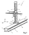
- figure 1 it is indicated as a whole by 1a horizontal-arm coordinate measuring machine.
- Machine 1 essentially comprises a base 2 provided with guides 3 along a horizontal axis X, a first carriage 4 mobile on the base 2 along the axis X and provided with guides 5 extending along a vertical axis Z, a second carriage 6 carried by the first carriage 4 and sliding along the axis Z, and a horizontal arm 7 carried by the second carriage 6, extending along a axis Y orthogonal to the axis X and axially mobile along the axis Y.
- One end of the arm 7 is adapted to carry a contact or optical detector (not shown) for measuring dimensional features of parts.
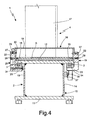
- base 2 ( figure 4 ) essentially consists of a box-type structure 10 elongated in the direction of the axis X, with constant section, having a flat horizontal bottom wall 11 and top wall 12, and a pair of vertical, reciprocally parallel side walls 13, 14.
- the side walls 13, 14 are reciprocally spaced at a distance smaller than the width of the walls 11, 12 so that these laterally protrude from the side walls 13, 14 with respective side wings 15.
- the sliding guides 3 for the first carriage 4 along the axis X are fixed under the side wings 15 of the top wall 12, which therefore presents a flat treadable upper surface, being free from guides and delicate components.
- the first carriage 4 comprises a lower base 16 mobile on the guides 3 and an upright 17 having a vertical axis tubular structure which extends upwards from the base 16 and carries the guides 5 for carriage 6.
- the base 16 consists of a central body 18 rigidly fastened to the upright 17 and a pair of side shoulders 19, 20 fixed to opposite sides of the central body 18 and each sliding along a respective guide 3.
- Each of the shoulders presents an essentially L-shaped section, with a vertical plate portion 22 adapted to be fastened to the central body 18 and a lower horizontal portion 23 extending underneath the respective wing 15.
- Ball circulation runners 24 cooperating with the respective guides 3 are fastened on portions 23, conveniently provided with inclined surfaces defining with the balls an "O"-type contact pattern.
- the contact pattern may be of the "X" type; according to another possible embodiment, the runners 24 may be replaced by runners of the pneumostatic type.
- the shoulder 20 presents longer extension along the axis X and is provided with two runners 24; a single runner is carried by shoulder 19. In this way, three rests and therefore an isostatic constraint system are defined as a whole on the guides 3. Such system is rigid according to all degrees of freedom, except for shifting along the axis X.
- the plate portions 22 of the shoulders 19, 20 are fastened to the central body by means of a plurality of screws 27, 28, in total six arranged on two horizontal rows of three in the example shown. Such screws 27, 28 throughly engage respective holes 29 made in the plate portions 22 and are adapted to be fastened in respective threaded holes 30 of the central body 18.
- the holes 30 on opposite sides of the central body 18 are paired and reciprocally coaxial.
- the mobile parts of the machine are moved, in a per se known way, by means of rack and pinion devices driven by respective electric motors 31, 32, 33.
- the first carriage 4 is actuated by an electric motor 31 carried by the shoulder 19 ( fig. 2 ), which provides motion via a belt 35 to a pulley 36 integral with a pinion 37 ( fig. 4 ) which meshes with a rack 38 fastened on the side wall 14 of the base 2 in direction parallel to the axis X.
- the actuating devices of the second carriage 6 and of the arm 7 are similar and are not described in detail.
- connection of the electric motors 31, 32, 33 to the respective power and control system is achieved by means of wirings (not shown) which are housed in articulated chains 40 in the transition zones between relatively moving parts.
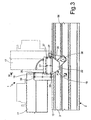
- figure 2 clearly shows a chain 40 associated to motor 31, which has one end secured to the base 2 and one end secured to the shoulder 19.
- the upright 17 of the machine 1 machine may be tipped and folded on the base 2 to favour the transportation of the machine 1 from the place of manufacture to the place of installation.
- the upright 17 may be tipped by removing all the screws (27) which connect the central body 18 to the side shoulders 19, 20 except for one screw (28) on each side ( fig. 3 ).
- a bracket 41 ( figure 2 ), fastened in conventional way, for example by means of simple screws, to an upper end of the upright 17, may be fastened to the upper surface 12 of the base, usually provided with holes, so as to lock the upright 17 in the tipped position.
- the horizontal arm 7 is appropriately removed and the second carriage 6 is arranged in its lowest position ( figures 2 and 3 ).
- screws 28 can be replaced by other articulated connection means, so as to allow the upright 17 to be tipped with respect to the shoulders 19, 20.
- Such tipping although preferably consisting of a simple rotation about an axis, may be also defined by a more complex motion.
- Screws 27 may be replaced by any releasable connection means.
- Larger measuring volume in the direction of the axis X may be obtained by joining several bases longitudinally.
Abstract
Description
- The present invention relates to a coordinate measuring machine of the horizontal-arm type.
- Coordinate measuring machines of the aforesaid type are known, comprising a base provided with guides along a first horizontal axis X, a first carriage mobile on the base along the axis X and comprising an upright provided with guides extending along a second vertical axis Z, a second carriage carried by the upright and sliding on the same along axis Z, and an arm carried by the second carriage and extending along a third horizontal axis Y orthogonal to the axis X. One end of the arm is adapted to carry a contact or optical detector for measuring the dimensional features of parts.
- Machines of this type may be used, for example, in the automotive industry, individually or in pairs, for dimensional monitoring of vehicle bodyworks on manufacturing lines; such machines are therefore large in size. For example, the measuring volume may be in the order of 6-7 m along axis X, 1.5-2 m along axis Y, and 2-3 m along axis Z.
- The coordinate machines of the type briefly described must be assembled and tested at the manufacturing plant, and therefore disassembled again, at least partially, to be transported to the installation plant. It is indeed unthinkable, given the dimensions of the concerned machines, to deliver them assembled.
- Such subsequent assembly and disassembly operations, as well as the component packing operations, are time-consuming and costly. A coordinate measuring machine with articulated connection means is disclosed in
GB-2191000 - It is therefore the object of the present invention to provide a horizontal-arm coordinate measuring machine which is free from the aforesaid technical problem.
- This object is achieved by a measuring machine according to
claim 1. - For a better understanding of the present invention, it will now be described a preferred embodiment by way of non-limitative example, and with reference to the accompanying drawings, in which:
-
figure 1 is a perspective view of a horizontal-arm coordinate measuring machine, in use position; -
figure 2 is a partial perspective view of the machine infigure 1 , in a partially disassembled and folded configuration; -
figure 3 is a side view, in a magnified scale, of a detail of the machine infigure 1 ; and -
figure 4 is a section taken along line IV-IV infigure 3 . - In
figure 1 , it is indicated as a whole by 1a horizontal-arm coordinate measuring machine. -
Machine 1 essentially comprises abase 2 provided withguides 3 along a horizontal axis X, afirst carriage 4 mobile on thebase 2 along the axis X and provided withguides 5 extending along a vertical axis Z, asecond carriage 6 carried by thefirst carriage 4 and sliding along the axis Z, and ahorizontal arm 7 carried by thesecond carriage 6, extending along a axis Y orthogonal to the axis X and axially mobile along the axis Y. One end of thearm 7 is adapted to carry a contact or optical detector (not shown) for measuring dimensional features of parts. - More specifically, base 2 (
figure 4 ) essentially consists of a box-type structure 10 elongated in the direction of the axis X, with constant section, having a flathorizontal bottom wall 11 andtop wall 12, and a pair of vertical, reciprocallyparallel side walls side walls walls side walls respective side wings 15. - The
sliding guides 3 for thefirst carriage 4 along the axis X are fixed under theside wings 15 of thetop wall 12, which therefore presents a flat treadable upper surface, being free from guides and delicate components. - The
first carriage 4 comprises alower base 16 mobile on theguides 3 and an upright 17 having a vertical axis tubular structure which extends upwards from thebase 16 and carries theguides 5 forcarriage 6. - More precisely (
figure 4 ), thebase 16 consists of acentral body 18 rigidly fastened to the upright 17 and a pair ofside shoulders central body 18 and each sliding along arespective guide 3. - Each of the shoulders presents an essentially L-shaped section, with a
vertical plate portion 22 adapted to be fastened to thecentral body 18 and a lowerhorizontal portion 23 extending underneath therespective wing 15. -
Ball circulation runners 24 cooperating with therespective guides 3 are fastened onportions 23, conveniently provided with inclined surfaces defining with the balls an "O"-type contact pattern. Alternatively, the contact pattern may be of the "X" type; according to another possible embodiment, therunners 24 may be replaced by runners of the pneumostatic type. - Conveniently, the
shoulder 20 presents longer extension along the axis X and is provided with tworunners 24; a single runner is carried byshoulder 19. In this way, three rests and therefore an isostatic constraint system are defined as a whole on theguides 3. Such system is rigid according to all degrees of freedom, except for shifting along the axis X. - The
plate portions 22 of theshoulders screws Such screws respective holes 29 made in theplate portions 22 and are adapted to be fastened in respective threadedholes 30 of thecentral body 18. Theholes 30 on opposite sides of thecentral body 18 are paired and reciprocally coaxial. - The mobile parts of the machine are moved, in a per se known way, by means of rack and pinion devices driven by respective
electric motors first carriage 4 is actuated by anelectric motor 31 carried by the shoulder 19 (fig. 2 ), which provides motion via abelt 35 to apulley 36 integral with a pinion 37 (fig. 4 ) which meshes with arack 38 fastened on theside wall 14 of thebase 2 in direction parallel to the axis X. The actuating devices of thesecond carriage 6 and of thearm 7 are similar and are not described in detail. - The connection of the
electric motors chains 40 in the transition zones between relatively moving parts. In particular,figure 2 clearly shows achain 40 associated tomotor 31, which has one end secured to thebase 2 and one end secured to theshoulder 19. - According to the present invention, the upright 17 of the
machine 1 machine may be tipped and folded on thebase 2 to favour the transportation of themachine 1 from the place of manufacture to the place of installation. - In particular, the upright 17 may be tipped by removing all the screws (27) which connect the
central body 18 to theside shoulders fig. 3 ). Thescrews 28, reciprocally coaxial, therefore define an axis of rotation A for thecentral body 18, and therefore for the upright 17 rigidly connected thereto, with respect to theshoulders guides 3. - It is therefore possible to fold the upright 17 on the
base 2 so as to reduce the overall dimensions of the machine for packing and transportation. - A bracket 41 (
figure 2 ), fastened in conventional way, for example by means of simple screws, to an upper end of the upright 17, may be fastened to theupper surface 12 of the base, usually provided with holes, so as to lock the upright 17 in the tipped position. Conveniently, before tipping the upright 17, thehorizontal arm 7 is appropriately removed and thesecond carriage 6 is arranged in its lowest position (figures 2 and3 ). - In this way, the costly operations of disassembly at the place of manufacture and reassembly at the place of use are avoided.
- It is to be noted that when upright 17 is tipped, the
electric motor 31 and therespective chain 40 are secured to theshoulder 19 and therefore the wiring is not subjected to abnormal stress during tipping. - It is finally apparent that changes and variations can be implemented to the
machine 1 described and illustrated without departing from the scope of protection of the claims as defined by the appended claims. - In particular,
screws 28 can be replaced by other articulated connection means, so as to allow the upright 17 to be tipped with respect to theshoulders -
Screws 27 may be replaced by any releasable connection means. - Larger measuring volume in the direction of the axis X may be obtained by joining several bases longitudinally.
Claims (11)
- Á coordinate measuring machine (1) comprising a base (2) provided with first guiding means (3) along a first, horizontal, axis (X), a first carriage (4) mobile on the base (2) along said first axis (X) and comprising an upright (17) provided with second guiding means (5) extending towards a second, vertical, axis (Z), a second carriage (6) carried by the upright (17) and sliding along said second axis (Z), and a horizontal arm (7) carried by the second carriage (6) extending along a third, horizontal, axis (Y) orthogonal to said first axis (X) and mobile along said third axis (Y), characterised in that the first carriage (4) comprises a base (16) provided with at least one first portion (19, 20) coupled to said first guiding means (3) and at least one second portion (18) rigidly connected to said upright (17), releasable connection means (27) for reciprocally connecting said first portion (19, 20) and said second portion of said carriage base (16), and articulated connection means (28) between said first portion (19, 20) and said second portion (18) of said carriage base (16) for allowing said upright (17) to be tipped with respect to said first portion (19, 20) when said releasable connection means (27) are released.
- A machine according to claim 1, characterised in that said articulated connection means (28) are hinge connection means defining an axis (A) of rotation of said second portion (18) with respect to said first portion (19, 20).
- A machine according to claim 1 or 2, characterised in that said first guiding means comprise a pair of side guides (3) carried by said base (2) and parallel to said first axis (X), and in that said second portion of said base (16) is defined by a central portion (18) of said base (16) rigidly connected to said upright (17), and in that said at least first portion of said base (16) is defined by a pair of side shoulders (19, 20) coupled to respective guides (3).
- A machine according to claim 3, characterised in that said releasable connection means comprise a plurality of first screws (27) which connect each of said shoulders (19, 20) to opposite sides of said central portion (18).
- A machine according to claim 3 or 4,
characterised in that said hinged connection means comprise a pair of reciprocally coaxial screws (28) which connect each of said shoulders (19, 20) to opposite sides of said central portion. - A machine according to any of the claims from 2 to 5, characterised in that said base (16) comprises ball circulation runners (24) coupled to said guides (3).
- A machine according to one of the preceding claims, characterised in that it comprises fastening means (41) for securing said upright onto said base (2) in a tipped position of said upright (17).
- A machine according to claim 7, characterised in that said fastening means comprise a bracket (41) fixable to an upper end of said upright (17) and an upper surface (12) of said base (2).
- A machine according to any of the claims from 3 to 8, characterised in that said first carriage (4), said second carriage (6) and said arm (7) are actuated by respective electric motors (31, 32, 33), the electric motor (31) operating said first carriage (4) being carried by one (19) of said side shoulders (19, 20).
- A machine according to claim 9, characterised in that it comprises an articulated chain (40) for protecting electrical power and control wirings of said electric motors (31, 32, 33) having one end fastened to the base (2) and one end fastened to said shoulder (19).
- A machine according to any of the preceding claims, characterised in that said base (2) has a flat treadable top wall (12) and in that said side guides (3) are fastened underneath said top wall (12) of said base (2).
Priority Applications (1)
| Application Number | Priority Date | Filing Date | Title |
|---|---|---|---|
| PL06745262T PL2013568T3 (en) | 2006-04-06 | 2006-04-06 | Horizontal-arm coordinate measuring machine |
Applications Claiming Priority (1)
| Application Number | Priority Date | Filing Date | Title |
|---|---|---|---|
| PCT/IT2006/000230 WO2007113879A1 (en) | 2006-04-06 | 2006-04-06 | Horizontal-arm coordinate measuring machine |
Publications (2)
| Publication Number | Publication Date |
|---|---|
| EP2013568A1 EP2013568A1 (en) | 2009-01-14 |
| EP2013568B1 true EP2013568B1 (en) | 2009-07-29 |
Family
ID=37056833
Family Applications (1)
| Application Number | Title | Priority Date | Filing Date |
|---|---|---|---|
| EP06745262A Active EP2013568B1 (en) | 2006-04-06 | 2006-04-06 | Horizontal-arm coordinate measuring machine |
Country Status (9)
| Country | Link |
|---|---|
| US (1) | US8042279B2 (en) |
| EP (1) | EP2013568B1 (en) |
| CN (1) | CN101460807B (en) |
| AT (1) | ATE438077T1 (en) |
| BR (1) | BRPI0621582A2 (en) |
| DE (1) | DE602006008192D1 (en) |
| ES (1) | ES2328736T3 (en) |
| PL (1) | PL2013568T3 (en) |
| WO (1) | WO2007113879A1 (en) |
Families Citing this family (3)
| Publication number | Priority date | Publication date | Assignee | Title |
|---|---|---|---|---|
| BRPI0621582A2 (en) * | 2006-04-06 | 2011-12-13 | Hexagon Metrology Spa | horizontal arm coordinate measuring machine |
| ES2525099B1 (en) | 2013-05-16 | 2015-09-18 | Unimetrik, S.A. | REMOVABLE NUMERICAL CONTROL MACHINE |
| WO2021232220A1 (en) * | 2020-05-19 | 2021-11-25 | 深圳元戎启行科技有限公司 | Distance measurement apparatus |
Family Cites Families (20)
| Publication number | Priority date | Publication date | Assignee | Title |
|---|---|---|---|---|
| IT1190574B (en) * | 1986-05-27 | 1988-02-16 | Dea Spa | COORDINATE MEASURING MACHINE |
| DE3920718A1 (en) | 1989-06-24 | 1991-01-10 | Leitz Wild Gmbh | FIXED PORTAL FOR A PRECISION COORDINATE MEASURING DEVICE |
| CN1067502A (en) * | 1992-05-03 | 1992-12-30 | 国营青岛前哨机械厂 | Horizontal arm type three-coordinate measuring machine |
| US5621978A (en) | 1993-07-14 | 1997-04-22 | Sarauer; Alan J. | Bar for coordinate measuring machine |
| DE4402061C1 (en) | 1994-01-25 | 1995-05-11 | Leitz Mestechnik Gmbh | Fixed portal (gantry) for precision coordinate measuring machines |
| JP3126114B2 (en) * | 1997-11-12 | 2001-01-22 | 株式会社ミツトヨ | Non-contact surface roughness measuring device |
| US6430828B1 (en) * | 1998-04-17 | 2002-08-13 | Electronic Measuring Devices, Inc. | Coordinate positioning apparatus with indexable stylus, components thereof, and method of using it |
| WO2002027269A1 (en) * | 2000-09-28 | 2002-04-04 | Carl Zeiss | Calibration of a measuring sensor on an appliance for measuring co-ordinates by means of a ball and two parameter fields |
| US20030037451A1 (en) * | 2001-08-27 | 2003-02-27 | Sarauer Alan J. | Vehicle frame measuring device |
| CN2527963Y (en) * | 2002-03-21 | 2002-12-25 | 曲殿光 | Regulating device for straight-line guide rail slide block of three coordinate measurer |
| GB0207298D0 (en) * | 2002-03-28 | 2002-05-08 | Renishaw Plc | Apparatus for changing operating modules on a coordinate positioning machine |
| DE10313038B4 (en) * | 2003-03-24 | 2005-02-17 | Klingelnberg Gmbh | Device for detecting the position of a probe element in a multi-coordinate measuring device |
| JP4568621B2 (en) * | 2005-02-28 | 2010-10-27 | 株式会社ミツトヨ | Straightness correction method for surface texture measuring instrument and surface texture measuring instrument |
| US7191540B1 (en) * | 2005-10-31 | 2007-03-20 | Mitutoyo Corporation | Work piece holder for surface measuring apparatus |
| US8091248B2 (en) * | 2006-04-06 | 2012-01-10 | Hexagon Metrology S.P.A. | Coordinate measuring machine |
| BRPI0621582A2 (en) * | 2006-04-06 | 2011-12-13 | Hexagon Metrology Spa | horizontal arm coordinate measuring machine |
| ES2339150T5 (en) * | 2006-04-18 | 2015-11-10 | Hexagon Metrology S.P.A. | Horizontal arm coordinate measuring machine |
| DE102006019382A1 (en) * | 2006-04-24 | 2007-10-25 | Carl Zeiss Industrielle Messtechnik Gmbh | Scanning a surface with a coordinate measuring machine |
| GB0713639D0 (en) * | 2007-07-13 | 2007-08-22 | Renishaw Plc | Error correction |
| DE102007051054A1 (en) * | 2007-10-19 | 2009-04-30 | Carl Zeiss Industrielle Messtechnik Gmbh | Method for correcting the measured values of a coordinate measuring machine and coordinate measuring machine |
-
2006
- 2006-04-06 BR BRPI0621582-3A patent/BRPI0621582A2/en active IP Right Grant
- 2006-04-06 CN CN2006800548753A patent/CN101460807B/en active Active
- 2006-04-06 PL PL06745262T patent/PL2013568T3/en unknown
- 2006-04-06 US US12/296,060 patent/US8042279B2/en active Active
- 2006-04-06 EP EP06745262A patent/EP2013568B1/en active Active
- 2006-04-06 DE DE602006008192T patent/DE602006008192D1/en active Active
- 2006-04-06 WO PCT/IT2006/000230 patent/WO2007113879A1/en active Application Filing
- 2006-04-06 AT AT06745262T patent/ATE438077T1/en not_active IP Right Cessation
- 2006-04-06 ES ES06745262T patent/ES2328736T3/en active Active
Also Published As
| Publication number | Publication date |
|---|---|
| US8042279B2 (en) | 2011-10-25 |
| CN101460807A (en) | 2009-06-17 |
| CN101460807B (en) | 2011-03-30 |
| PL2013568T3 (en) | 2009-10-30 |
| BRPI0621582A2 (en) | 2011-12-13 |
| US20100218393A1 (en) | 2010-09-02 |
| ES2328736T3 (en) | 2009-11-17 |
| DE602006008192D1 (en) | 2009-09-10 |
| ATE438077T1 (en) | 2009-08-15 |
| WO2007113879A1 (en) | 2007-10-11 |
| EP2013568A1 (en) | 2009-01-14 |
Similar Documents
| Publication | Publication Date | Title |
|---|---|---|
| CN101351394B (en) | Device for adjusting tracks on a conveyor | |
| US6322854B1 (en) | Multiple head dispensing method | |
| EP2013568B1 (en) | Horizontal-arm coordinate measuring machine | |
| KR101155961B1 (en) | Two dimension driving inspection apparatus replaced 1 axis by conveyor | |
| TWI431713B (en) | Stage device | |
| EP2425943A1 (en) | A woodworking drilling machine with an improved panel drilling unit | |
| US8091248B2 (en) | Coordinate measuring machine | |
| CN109632292A (en) | A kind of gear-box torque test equipment | |
| KR20080102223A (en) | Multi-joint robot and wiring method | |
| KR200408958Y1 (en) | a bottom jig of a tester | |
| WO2013008488A1 (en) | Assembly work conveyor device | |
| KR100682620B1 (en) | Handler for industry robot | |
| CN111319063A (en) | Method for manufacturing robot | |
| KR100629379B1 (en) | Cantilever panel carrier | |
| CN219313828U (en) | Transfer machine with wide application range and adjustable conveying assembly spacing | |
| CN220040249U (en) | Tobacco material moisture detection equipment | |
| CN208437924U (en) | A kind of pneumatically lower screws apptss | |
| KR102098401B1 (en) | Desk-top robot | |
| CN214297808U (en) | Synchronous belt module | |
| KR20120065250A (en) | Workpiece positioning device and production system using it | |
| CN216793642U (en) | Wafer shifting device | |
| JPH11830A (en) | Workpiece transfer device | |
| CN214818562U (en) | ABB robot with stable clamping function | |
| CN113835011A (en) | Automatic device of dotting of extension of circuit board electricity tester | |
| KR101111396B1 (en) | Test handler and carrier board conveyance system for test handler |
Legal Events
| Date | Code | Title | Description |
|---|---|---|---|
| PUAI | Public reference made under article 153(3) epc to a published international application that has entered the european phase |
Free format text: ORIGINAL CODE: 0009012 |
|
| 17P | Request for examination filed |
Effective date: 20081031 |
|
| AK | Designated contracting states |
Kind code of ref document: A1 Designated state(s): AT BE BG CH CY CZ DE DK EE ES FI FR GB GR HU IE IS IT LI LT LU LV MC NL PL PT RO SE SI SK TR |
|
| AX | Request for extension of the european patent |
Extension state: AL BA HR MK YU |
|
| GRAP | Despatch of communication of intention to grant a patent |
Free format text: ORIGINAL CODE: EPIDOSNIGR1 |
|
| GRAC | Information related to communication of intention to grant a patent modified |
Free format text: ORIGINAL CODE: EPIDOSCIGR1 |
|
| GRAS | Grant fee paid |
Free format text: ORIGINAL CODE: EPIDOSNIGR3 |
|
| GRAA | (expected) grant |
Free format text: ORIGINAL CODE: 0009210 |
|
| AK | Designated contracting states |
Kind code of ref document: B1 Designated state(s): AT BE BG CH CY CZ DE DK EE ES FI FR GB GR HU IE IS IT LI LT LU LV MC NL PL PT RO SE SI SK TR |
|
| REG | Reference to a national code |
Ref country code: GB Ref legal event code: FG4D |
|
| REG | Reference to a national code |
Ref country code: CH Ref legal event code: EP |
|
| REG | Reference to a national code |
Ref country code: IE Ref legal event code: FG4D |
|
| REG | Reference to a national code |
Ref country code: CH Ref legal event code: NV Representative=s name: MOINAS & SAVOYE SA |
|
| REF | Corresponds to: |
Ref document number: 602006008192 Country of ref document: DE Date of ref document: 20090910 Kind code of ref document: P |
|
| REG | Reference to a national code |
Ref country code: PL Ref legal event code: T3 |
|
| REG | Reference to a national code |
Ref country code: ES Ref legal event code: FG2A Ref document number: 2328736 Country of ref document: ES Kind code of ref document: T3 |
|
| PG25 | Lapsed in a contracting state [announced via postgrant information from national office to epo] |
Ref country code: LT Free format text: LAPSE BECAUSE OF FAILURE TO SUBMIT A TRANSLATION OF THE DESCRIPTION OR TO PAY THE FEE WITHIN THE PRESCRIBED TIME-LIMIT Effective date: 20090729 Ref country code: IS Free format text: LAPSE BECAUSE OF FAILURE TO SUBMIT A TRANSLATION OF THE DESCRIPTION OR TO PAY THE FEE WITHIN THE PRESCRIBED TIME-LIMIT Effective date: 20091129 Ref country code: AT Free format text: LAPSE BECAUSE OF FAILURE TO SUBMIT A TRANSLATION OF THE DESCRIPTION OR TO PAY THE FEE WITHIN THE PRESCRIBED TIME-LIMIT Effective date: 20090729 Ref country code: FI Free format text: LAPSE BECAUSE OF FAILURE TO SUBMIT A TRANSLATION OF THE DESCRIPTION OR TO PAY THE FEE WITHIN THE PRESCRIBED TIME-LIMIT Effective date: 20090729 Ref country code: SE Free format text: LAPSE BECAUSE OF FAILURE TO SUBMIT A TRANSLATION OF THE DESCRIPTION OR TO PAY THE FEE WITHIN THE PRESCRIBED TIME-LIMIT Effective date: 20090729 |
|
| PG25 | Lapsed in a contracting state [announced via postgrant information from national office to epo] |
Ref country code: SI Free format text: LAPSE BECAUSE OF FAILURE TO SUBMIT A TRANSLATION OF THE DESCRIPTION OR TO PAY THE FEE WITHIN THE PRESCRIBED TIME-LIMIT Effective date: 20090729 Ref country code: LV Free format text: LAPSE BECAUSE OF FAILURE TO SUBMIT A TRANSLATION OF THE DESCRIPTION OR TO PAY THE FEE WITHIN THE PRESCRIBED TIME-LIMIT Effective date: 20090729 |
|
| PG25 | Lapsed in a contracting state [announced via postgrant information from national office to epo] |
Ref country code: PT Free format text: LAPSE BECAUSE OF FAILURE TO SUBMIT A TRANSLATION OF THE DESCRIPTION OR TO PAY THE FEE WITHIN THE PRESCRIBED TIME-LIMIT Effective date: 20091129 Ref country code: BG Free format text: LAPSE BECAUSE OF FAILURE TO SUBMIT A TRANSLATION OF THE DESCRIPTION OR TO PAY THE FEE WITHIN THE PRESCRIBED TIME-LIMIT Effective date: 20091029 |
|
| PG25 | Lapsed in a contracting state [announced via postgrant information from national office to epo] |
Ref country code: DK Free format text: LAPSE BECAUSE OF FAILURE TO SUBMIT A TRANSLATION OF THE DESCRIPTION OR TO PAY THE FEE WITHIN THE PRESCRIBED TIME-LIMIT Effective date: 20090729 Ref country code: EE Free format text: LAPSE BECAUSE OF FAILURE TO SUBMIT A TRANSLATION OF THE DESCRIPTION OR TO PAY THE FEE WITHIN THE PRESCRIBED TIME-LIMIT Effective date: 20090729 Ref country code: CZ Free format text: LAPSE BECAUSE OF FAILURE TO SUBMIT A TRANSLATION OF THE DESCRIPTION OR TO PAY THE FEE WITHIN THE PRESCRIBED TIME-LIMIT Effective date: 20090729 Ref country code: RO Free format text: LAPSE BECAUSE OF FAILURE TO SUBMIT A TRANSLATION OF THE DESCRIPTION OR TO PAY THE FEE WITHIN THE PRESCRIBED TIME-LIMIT Effective date: 20090729 |
|
| PG25 | Lapsed in a contracting state [announced via postgrant information from national office to epo] |
Ref country code: SK Free format text: LAPSE BECAUSE OF FAILURE TO SUBMIT A TRANSLATION OF THE DESCRIPTION OR TO PAY THE FEE WITHIN THE PRESCRIBED TIME-LIMIT Effective date: 20090729 Ref country code: BE Free format text: LAPSE BECAUSE OF FAILURE TO SUBMIT A TRANSLATION OF THE DESCRIPTION OR TO PAY THE FEE WITHIN THE PRESCRIBED TIME-LIMIT Effective date: 20090729 |
|
| PLBE | No opposition filed within time limit |
Free format text: ORIGINAL CODE: 0009261 |
|
| STAA | Information on the status of an ep patent application or granted ep patent |
Free format text: STATUS: NO OPPOSITION FILED WITHIN TIME LIMIT |
|
| 26N | No opposition filed |
Effective date: 20100503 |
|
| PG25 | Lapsed in a contracting state [announced via postgrant information from national office to epo] |
Ref country code: GR Free format text: LAPSE BECAUSE OF FAILURE TO SUBMIT A TRANSLATION OF THE DESCRIPTION OR TO PAY THE FEE WITHIN THE PRESCRIBED TIME-LIMIT Effective date: 20091030 |
|
| PG25 | Lapsed in a contracting state [announced via postgrant information from national office to epo] |
Ref country code: MC Free format text: LAPSE BECAUSE OF NON-PAYMENT OF DUE FEES Effective date: 20100430 |
|
| PG25 | Lapsed in a contracting state [announced via postgrant information from national office to epo] |
Ref country code: IE Free format text: LAPSE BECAUSE OF NON-PAYMENT OF DUE FEES Effective date: 20100406 |
|
| REG | Reference to a national code |
Ref country code: DE Ref legal event code: R082 Ref document number: 602006008192 Country of ref document: DE Representative=s name: KAMINSKI HARMANN PATENTANWAELTE AG, LI |
|
| PG25 | Lapsed in a contracting state [announced via postgrant information from national office to epo] |
Ref country code: CY Free format text: LAPSE BECAUSE OF FAILURE TO SUBMIT A TRANSLATION OF THE DESCRIPTION OR TO PAY THE FEE WITHIN THE PRESCRIBED TIME-LIMIT Effective date: 20090729 |
|
| PG25 | Lapsed in a contracting state [announced via postgrant information from national office to epo] |
Ref country code: HU Free format text: LAPSE BECAUSE OF FAILURE TO SUBMIT A TRANSLATION OF THE DESCRIPTION OR TO PAY THE FEE WITHIN THE PRESCRIBED TIME-LIMIT Effective date: 20100130 Ref country code: LU Free format text: LAPSE BECAUSE OF NON-PAYMENT OF DUE FEES Effective date: 20100406 |
|
| PG25 | Lapsed in a contracting state [announced via postgrant information from national office to epo] |
Ref country code: TR Free format text: LAPSE BECAUSE OF FAILURE TO SUBMIT A TRANSLATION OF THE DESCRIPTION OR TO PAY THE FEE WITHIN THE PRESCRIBED TIME-LIMIT Effective date: 20090729 |
|
| REG | Reference to a national code |
Ref country code: FR Ref legal event code: PLFP Year of fee payment: 10 |
|
| REG | Reference to a national code |
Ref country code: FR Ref legal event code: PLFP Year of fee payment: 11 |
|
| REG | Reference to a national code |
Ref country code: CH Ref legal event code: PFA Owner name: HEXAGON METROLOGY S.P.A., IT Free format text: FORMER OWNER: HEXAGON METROLOGY S.P.A., IT |
|
| REG | Reference to a national code |
Ref country code: FR Ref legal event code: PLFP Year of fee payment: 12 |
|
| REG | Reference to a national code |
Ref country code: FR Ref legal event code: PLFP Year of fee payment: 13 |
|
| PGFP | Annual fee paid to national office [announced via postgrant information from national office to epo] |
Ref country code: PL Payment date: 20200323 Year of fee payment: 15 |
|
| PGFP | Annual fee paid to national office [announced via postgrant information from national office to epo] |
Ref country code: NL Payment date: 20200428 Year of fee payment: 15 Ref country code: CH Payment date: 20200424 Year of fee payment: 15 Ref country code: FR Payment date: 20200429 Year of fee payment: 15 Ref country code: ES Payment date: 20200511 Year of fee payment: 15 |
|
| PGFP | Annual fee paid to national office [announced via postgrant information from national office to epo] |
Ref country code: GB Payment date: 20200429 Year of fee payment: 15 |
|
| REG | Reference to a national code |
Ref country code: NL Ref legal event code: MM Effective date: 20210501 |
|
| GBPC | Gb: european patent ceased through non-payment of renewal fee |
Effective date: 20210406 |
|
| PG25 | Lapsed in a contracting state [announced via postgrant information from national office to epo] |
Ref country code: LI Free format text: LAPSE BECAUSE OF NON-PAYMENT OF DUE FEES Effective date: 20210430 Ref country code: CH Free format text: LAPSE BECAUSE OF NON-PAYMENT OF DUE FEES Effective date: 20210430 Ref country code: FR Free format text: LAPSE BECAUSE OF NON-PAYMENT OF DUE FEES Effective date: 20210430 Ref country code: GB Free format text: LAPSE BECAUSE OF NON-PAYMENT OF DUE FEES Effective date: 20210406 |
|
| PG25 | Lapsed in a contracting state [announced via postgrant information from national office to epo] |
Ref country code: NL Free format text: LAPSE BECAUSE OF NON-PAYMENT OF DUE FEES Effective date: 20210501 |
|
| REG | Reference to a national code |
Ref country code: ES Ref legal event code: FD2A Effective date: 20220630 |
|
| PG25 | Lapsed in a contracting state [announced via postgrant information from national office to epo] |
Ref country code: ES Free format text: LAPSE BECAUSE OF NON-PAYMENT OF DUE FEES Effective date: 20210407 |
|
| PG25 | Lapsed in a contracting state [announced via postgrant information from national office to epo] |
Ref country code: PL Free format text: LAPSE BECAUSE OF NON-PAYMENT OF DUE FEES Effective date: 20210406 |
|
| PGFP | Annual fee paid to national office [announced via postgrant information from national office to epo] |
Ref country code: IT Payment date: 20230405 Year of fee payment: 18 Ref country code: DE Payment date: 20230427 Year of fee payment: 18 |