EP2012192A1 - Dispositif de fixation et appareil de formation d'images - Google Patents
Dispositif de fixation et appareil de formation d'images Download PDFInfo
- Publication number
- EP2012192A1 EP2012192A1 EP08158125A EP08158125A EP2012192A1 EP 2012192 A1 EP2012192 A1 EP 2012192A1 EP 08158125 A EP08158125 A EP 08158125A EP 08158125 A EP08158125 A EP 08158125A EP 2012192 A1 EP2012192 A1 EP 2012192A1
- Authority
- EP
- European Patent Office
- Prior art keywords
- fixing belt
- fixing
- sliding sheet
- inner peripheral
- peripheral surface
- Prior art date
- Legal status (The legal status is an assumption and is not a legal conclusion. Google has not performed a legal analysis and makes no representation as to the accuracy of the status listed.)
- Granted
Links
Images

Classifications
-
- G—PHYSICS
- G03—PHOTOGRAPHY; CINEMATOGRAPHY; ANALOGOUS TECHNIQUES USING WAVES OTHER THAN OPTICAL WAVES; ELECTROGRAPHY; HOLOGRAPHY
- G03G—ELECTROGRAPHY; ELECTROPHOTOGRAPHY; MAGNETOGRAPHY
- G03G15/00—Apparatus for electrographic processes using a charge pattern
- G03G15/20—Apparatus for electrographic processes using a charge pattern for fixing, e.g. by using heat
- G03G15/2003—Apparatus for electrographic processes using a charge pattern for fixing, e.g. by using heat using heat
- G03G15/2014—Apparatus for electrographic processes using a charge pattern for fixing, e.g. by using heat using heat using contact heat
- G03G15/2053—Structural details of heat elements, e.g. structure of roller or belt, eddy current, induction heating
- G03G15/2057—Structural details of heat elements, e.g. structure of roller or belt, eddy current, induction heating relating to the chemical composition of the heat element and layers thereof
-
- G—PHYSICS
- G03—PHOTOGRAPHY; CINEMATOGRAPHY; ANALOGOUS TECHNIQUES USING WAVES OTHER THAN OPTICAL WAVES; ELECTROGRAPHY; HOLOGRAPHY
- G03G—ELECTROGRAPHY; ELECTROPHOTOGRAPHY; MAGNETOGRAPHY
- G03G2215/00—Apparatus for electrophotographic processes
- G03G2215/20—Details of the fixing device or porcess
- G03G2215/2003—Structural features of the fixing device
- G03G2215/2009—Pressure belt
Definitions
- the present invention relates to fixing devices of the FBNF (Free Belt Nip Fuser) method having a fixing belt, to fixing belts used in such fixing devices, and to image forming apparatuses having such fixing devices.
- FBNF Free Belt Nip Fuser
- a latent image corresponding to the original is formed on a photoreceptor drum, this latent image is made visible by giving toners to it, this visible toner image is transferred onto a recording material, and after that, the toner image on the recording material is fixed and then the recording material is discharged to outside the apparatus.
- latent images of colors Y, M, C, and K corresponding to the colors of the original are formed on four photoreceptor drums, the toner images of four colors made visible are primary-transferred on to an endless intermediate belt, then they are secondary-transferred on to a recording medium, then toner image transferred on to the recording medium is fixed, and then the recording material is discharged to outside the apparatus.
- a fixing device for fixing such toner images As a fixing device for fixing such toner images is present a fixing device of the heated roller method that applies heat and pressure by gripping and conveying the recording medium with the toner image transferred on to it in a nip portion formed by a fixing roller having inside it a heating member such as a halogen lamp, etc., and a pressure roller that applies pressure on the fixing roller, and such a fixing device is being used widely because its construction is simple.
- the nip width along the axial direction may sometimes become uneven, and there is the possibility of uneven fixing or wrinkles of the recording material occurring. Further, if the roller diameters are increased, there is the problem that not only the fixing device becomes big but also the warming up time becomes long.
- a fixing device of the so-called FBNF method has been disclosed in the Unexamined Japanese Patent Application Publications (see publication No. 2005-173441 , No. 2004-198655 , and No. 2004-206105 ), wherein the fixing device is provided with a fixing roller having an elastic layer made of silicone rubber and a heating member such as a halogen lamp, etc., built in at the center and rotating, an endless fixing belt that rotates being driven by the fixing roller, a pressure pad that presses against the fixing roller via the fixing belt from the inside of the fixing belt, and a low friction sliding sheet placed between the fixing belt and the pressure pad, and in the nip portion formed by the fixing roller and the fixing belt, the recording material on to which the toner image has been transferred is heated and pressed while being gripped and conveyed.
- a fixing roller having an elastic layer made of silicone rubber and a heating member such as a halogen lamp, etc.
- the fixing belt pressed to the fixing roller by the pressure pad deforms elastically, and a wide nip section is formed between the fixing roller and the fixing belt. Consequently, it is possible to achieve high speeds, and also the fixing device does not become big. In addition, since the thermal capacity of the fixing belt is small, the warming up time becomes short and it is possible to save energy.
- the conventional sliding sheet is formed to be porous in order to retain the lubricating agent, since it cannot withstand use for a long time, the sliding surface of the sliding sheet is made porous and to include a fluoroplastic.
- PTFE has been disclosed as the material of the releasing layer of the fixing belt and also PTFE has been disclosed as the material of the sliding sheet.
- An object of the present invention is to solve the above mentioned problem.
- One aspect of the present invention is a fixing device including:
- the present image forming apparatus comprises an image forming apparatus main unit GH and an image reading apparatus YS.
- the image forming apparatus main unit GH is one that is called a tandem type color image forming apparatus and has a plurality of image forming section 10Y, 10M, 10C, and 10K, a belt shaped intermediate image transfer belt 6, a sheet conveying section, a fixing device 9, etc.
- an image reading apparatus YS made of an automatic document feeding apparatus 201 and a document image scanning exposure apparatus 202.
- a document d placed on the document table of the automatic document feeding apparatus 201 is conveyed by a conveying section, the image on one side or both sides of the document is scanned and exposed by the optical system of the document image scanning exposure apparatus 202, and is read out by the line image sensor CCD.
- the signal formed by photoelectric conversion by the line image sensor CCD is subjected to analog processing, A/D conversion, shading correction, image compression processing, etc., in the image processing section, and is then sent to the exposure sections 3Y, 3M, 3C, and 3K.
- the image forming section 10Y that forms images of yellow (Y) color has a charging section 2Y, an exposing section 3Y, a developing section 4Y, and a cleaning section 8Y placed around the photoreceptor drum 1Y.
- the image forming section 10M that forms images of magenta (M) color has a charging section 2M, an exposing section 3M, a developing section 4M, and a cleaning section 8M placed around the photoreceptor drum 1M.
- the image forming section 10C that forms images of cyan (C) color has a charging section 2C, an exposing section 3C, a developing section 4C, and a cleaning section 8C placed around the photoreceptor drum 1C.
- the image forming section 10K that forms images of black (K) color has a charging section 2K, an exposing section 3K, a developing section 4K, and a cleaning section 8K placed around the photoreceptor drum 1K. Further, the charging section 2Y and the exposing section 3Y, the charging section 2M and the exposing section 3M, the charging section 2C and the exposing section 3C, the charging section 2K and the exposing section 3K respectively constitute latent image forming sections.
- the developing sections 4Y, 4M, 4C, and 4K contain two-component developing agents having a carrier and a small particle diameter toner of colors yellow (Y), magenta (M), cyan (C), 1 and black (K).
- the intermediate image transfer member 6 is wound around a plurality of rollers and is supported in a rotatable manner.
- the fixing device 100 fixes the toner image on the recording sheet (the recording material) P by applying heat and pressure in the nip portion formed between the heated fixing roller 101 and the fixing belt 102.
- the images of different colors formed by the image forming sections 10Y, 10M, 10C, and 10K are successively transferred (primary transfer) by the transfer sections 7Y, 7M, 7C, and 7K on to the rotating intermediate image transfer member 6, thereby forming a toner image in which a color image is synthesized.
- the recording sheet P stored inside the sheet feeding cassette is fed by the sheet feeding section 21, passes over the sheet feeding rollers 22A, 22B, 22C, 22D, and the registration roller 23, etc., is conveyed to the transfer section 7A, and the color image is transferred onto the recording sheet P (secondary transfer).
- the recording sheet P on to which a color image has been transferred is subjected to heat and pressure in the fixing device 100 thereby fixing the color toner image on the recording sheet P. Thereafter, it is gripped by the sheet discharge roller 24 and is placed on the sheet discharge tray 25 outside the equipment.
- the intermediate image transfer member 6 from which the recording sheet P has been separated by bending has residual toner on it removed by the cleaning section 8A.
- the above was an image forming apparatus that forms color images, it can also be an image forming apparatus that forms monochrome images, and the intermediate image transfer member may or may not be used.
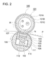
- Figure 2 is a cross-sectional diagram in a direction at right angles to the longitudinal direction of the fixing device.
- the fixing roller 101 has a halogen lamp (heating member) built in at the its center, and is constituted from a cylindrical shaped core metal 101A formed from aluminum, iron, etc., an elastic layer 101B made of silicone rubber with a high thermal resistance and covering the core metal 101A, and in addition, a releasing layer 101C made of a fluoroplastic such as perfluoroalkoxy (herein after abbreviated as PFA) or polytetrafluoroethylene (hereinafter abbreviated as PTFE).
- PFA perfluoroalkoxy
- PTFE polytetrafluoroethylene
- the fixing belt 102 is constituted from a base formed by polyimide with a thickness of about 100 ⁇ m and a releasing layer within a thickness of about 25 ⁇ m made of PFA or PTFE covering the outside surface of the base, and is formed in an endless shape. Further, since the figure becomes unclear if a base and releasing layer are written for the thin fixing belt 102, they have been omitted.
- the pressure pad 103 as a pressure member, is formed from a silicone rubber that is softer than the elastic layer 101B and is held by a holder 108 made of a heat resistant plastic along with a metal base plate 104 made of stainless steel and a base member 105 made of a heat resistant plastic. Further, a compression spring 106 is provided for the base member 105.
- the pressing section corresponds to the pressing pad 103, the metal base plate 104, the base member 105, and the compression spring 106.
- the separating member 107 is placed on the downstream side of the direction of conveying the recording sheet P in order to increase the separation characteristics of the fixed recording sheet P.
- the leading edge part of the separating member is formed in the shape of an arc with a large curvature using a heat resistant plastic or a metal such as aluminum, and is held by a holder 109 made of a heat resistant plastic via a metal base plate 104, etc., and a metal frame 110.
- the separating section corresponds to the separating member 107.
- the holders 108 and 109 are held by a frame 110 placed at the center.
- the holding section corresponds to the holders 108 and 109 and the frame 110.
- the sliding sheet 111 is made of a Teflon ® coated glass fiber sheet or PTFE sheet and is placed between the inner peripheral surface of the fixing belt 102 and the pressure pad 103 and between the inner peripheral surface of the fixing belt 102 and the separating member 107, and one of its ends is fixed to the holder 109.
- the oil pad 112 (the lubricating agent supplying section) formed from a sponge, etc., contains a lubricating agent such as a silicone oil, etc., is held by the holder 109 and is in pressure contact with the inner peripheral surface of the fixing belt 102.
- the holder 109 also has the function of a guiding member that guides the fixing belt 102 during the rotation of the fixing belt 102.
- the fixing roller which is heated by a halogen lamp H and driven by a driving section not shown in the figure, rotates in the clockwise direction. Also, the pressure pad 103 is pressed by the compression spring via the metal base plate 104 and the base member 105, and presses the fixing belt 102 from its inner peripheral surface via the sliding sheet 111 and presses it against the fixing roller 101.
- the fixing belt 102 rotates in the anticlockwise direction due to the rotation of the fixing roller 101, and since it is elastically deformed in a concave shape along with the pressure pad 103 due to being pressed against the fixing roller 101, a wide nip portion N is formed between the fixing belt 102 and the fixing roller 101.
- the conveyed recording sheet P is gripped and pressed in the nip portion N, and the unfixed toner on the recording sheet P is fixed by the application of heat and pressure.
- the sliding sheet is formed of a material with a small coefficient of friction, the sliding resistance between the two is small.
- a silicone oil, etc. is supplied to the inner peripheral surface of the fixing belt 102 as a lubricating agent from the oil pad 112, the sliding resistance becomes even smaller.
- the separating member 107 presses the fixing belt 102 against the fixing roller 101 via the sliding sheet 111 and causes the elastic layer 101B and the releasing layer 101C of the fixing roller to get elastically deformed in a concave shape with a large curvature. Therefore, the recording sheet P fixed in the nip portion N definitely gets peeled off and separated from the fixing roller 101 without having to use a separating claw, etc.
Landscapes
- Physics & Mathematics (AREA)
- General Physics & Mathematics (AREA)
- Fixing For Electrophotography (AREA)
Applications Claiming Priority (1)
| Application Number | Priority Date | Filing Date | Title |
|---|---|---|---|
| JP2007174938A JP2009014893A (ja) | 2007-07-03 | 2007-07-03 | 定着装置、定着ベルト及び画像形成装置 |
Publications (2)
| Publication Number | Publication Date |
|---|---|
| EP2012192A1 true EP2012192A1 (fr) | 2009-01-07 |
| EP2012192B1 EP2012192B1 (fr) | 2013-12-11 |
Family
ID=39821016
Family Applications (1)
| Application Number | Title | Priority Date | Filing Date |
|---|---|---|---|
| EP08158125.8A Ceased EP2012192B1 (fr) | 2007-07-03 | 2008-06-12 | Dispositif de fixation et appareil de formation d'images |
Country Status (4)
| Country | Link |
|---|---|
| US (1) | US7711305B2 (fr) |
| EP (1) | EP2012192B1 (fr) |
| JP (1) | JP2009014893A (fr) |
| CN (1) | CN101339394B (fr) |
Cited By (1)
| Publication number | Priority date | Publication date | Assignee | Title |
|---|---|---|---|---|
| CN104155867A (zh) * | 2013-05-14 | 2014-11-19 | 富士施乐株式会社 | 定影装置及图像形成装置 |
Families Citing this family (20)
| Publication number | Priority date | Publication date | Assignee | Title |
|---|---|---|---|---|
| JP4412373B2 (ja) * | 2007-09-14 | 2010-02-10 | コニカミノルタビジネステクノロジーズ株式会社 | 定着装置及び画像形成装置 |
| US8320810B2 (en) * | 2009-01-22 | 2012-11-27 | Lexmark International, Inc. | Belt fuser having a protuberance for an imaging device |
| JP2010243621A (ja) * | 2009-04-02 | 2010-10-28 | Oki Data Corp | 定着装置、画像形成装置及び加圧部材の製造方法。 |
| JP5233837B2 (ja) * | 2009-05-18 | 2013-07-10 | コニカミノルタビジネステクノロジーズ株式会社 | 定着装置及び画像形成装置 |
| JP5403264B2 (ja) * | 2010-01-13 | 2014-01-29 | 株式会社リコー | 定着装置及び画像形成装置 |
| JP5979840B2 (ja) * | 2011-09-30 | 2016-08-31 | キヤノン株式会社 | 交換用定着ベルト及び定着ベルトの交換方法 |
| JP6141026B2 (ja) * | 2012-02-27 | 2017-06-07 | キヤノン株式会社 | 画像加熱装置 |
| JP6171847B2 (ja) * | 2013-10-28 | 2017-08-02 | 富士ゼロックス株式会社 | 摺動部材、定着装置及び画像形成装置 |
| JP6979164B2 (ja) * | 2017-03-17 | 2021-12-08 | 株式会社リコー | 定着装置、画像形成装置 |
| JP7081208B2 (ja) * | 2018-02-28 | 2022-06-07 | コニカミノルタ株式会社 | 定着装置および画像形成装置 |
| JP2020148943A (ja) * | 2019-03-14 | 2020-09-17 | 株式会社リコー | 加熱部材、加熱装置、定着装置及び画像形成装置 |
| JP7302319B2 (ja) * | 2019-06-14 | 2023-07-04 | 株式会社リコー | 定着装置、定着装置製造方法、及び画像形成装置 |
| JP2021005026A (ja) * | 2019-06-27 | 2021-01-14 | 株式会社リコー | 定着装置および画像形成装置 |
| JP7612992B2 (ja) * | 2020-01-21 | 2025-01-15 | 沖電気工業株式会社 | 定着装置および画像形成装置 |
| US11537074B2 (en) * | 2020-12-04 | 2022-12-27 | Brother Kogyo Kabushiki Kaisha | Fixing device |
| US11635718B2 (en) | 2021-03-17 | 2023-04-25 | Ricoh Company, Ltd. | Fixing device and image forming apparatus incorporating same |
| US11592770B2 (en) | 2021-03-19 | 2023-02-28 | Ricoh Company, Ltd. | Pressing device, fixing device, and image forming apparatus incorporating fixing device |
| JP7808268B2 (ja) * | 2021-03-23 | 2026-01-29 | 株式会社リコー | 定着装置および画像形成装置 |
| JP2024142150A (ja) * | 2023-03-29 | 2024-10-10 | 富士フイルムビジネスイノベーション株式会社 | 樹脂ベルト、定着ベルト、定着装置及び画像形成装置 |
| JP2025104895A (ja) * | 2023-12-28 | 2025-07-10 | 富士フイルムビジネスイノベーション株式会社 | 定着装置、及び画像形成装置 |
Citations (2)
| Publication number | Priority date | Publication date | Assignee | Title |
|---|---|---|---|---|
| US20040131401A1 (en) | 2002-12-12 | 2004-07-08 | Fuji Xerox Co., Ltd. | Sliding member for electrophotographic apparatus and fixing device using the same |
| US20070071514A1 (en) | 2005-03-15 | 2007-03-29 | Ricoh Printing Systems, Ltd. | Fixing apparatus and image forming apparatus |
Family Cites Families (6)
| Publication number | Priority date | Publication date | Assignee | Title |
|---|---|---|---|---|
| JP4227286B2 (ja) * | 2000-05-17 | 2009-02-18 | キヤノン株式会社 | 画像形成システム及びその制御方法、並びに記憶媒体 |
| US6564033B2 (en) * | 2000-12-12 | 2003-05-13 | Canon Kabushiki Kaisha | Fixing belt and image heating and fixing apparatus |
| JP4543670B2 (ja) | 2002-12-12 | 2010-09-15 | 富士ゼロックス株式会社 | 定着装置 |
| JP4178939B2 (ja) * | 2002-12-17 | 2008-11-12 | 富士ゼロックス株式会社 | 定着装置、およびそれを用いた電子写真装置 |
| JP4194476B2 (ja) * | 2003-11-13 | 2008-12-10 | キヤノン株式会社 | 文書処理装置及び文書処理方法 |
| JP2005173441A (ja) * | 2003-12-15 | 2005-06-30 | Fuji Xerox Co Ltd | 定着装置および画像形成装置 |
-
2007
- 2007-07-03 JP JP2007174938A patent/JP2009014893A/ja active Pending
-
2008
- 2008-06-09 US US12/157,294 patent/US7711305B2/en active Active
- 2008-06-12 EP EP08158125.8A patent/EP2012192B1/fr not_active Ceased
- 2008-07-02 CN CN2008101276437A patent/CN101339394B/zh active Active
Patent Citations (2)
| Publication number | Priority date | Publication date | Assignee | Title |
|---|---|---|---|---|
| US20040131401A1 (en) | 2002-12-12 | 2004-07-08 | Fuji Xerox Co., Ltd. | Sliding member for electrophotographic apparatus and fixing device using the same |
| US20070071514A1 (en) | 2005-03-15 | 2007-03-29 | Ricoh Printing Systems, Ltd. | Fixing apparatus and image forming apparatus |
Cited By (2)
| Publication number | Priority date | Publication date | Assignee | Title |
|---|---|---|---|---|
| CN104155867A (zh) * | 2013-05-14 | 2014-11-19 | 富士施乐株式会社 | 定影装置及图像形成装置 |
| CN104155867B (zh) * | 2013-05-14 | 2018-06-08 | 富士施乐株式会社 | 定影装置及图像形成装置 |
Also Published As
| Publication number | Publication date |
|---|---|
| CN101339394A (zh) | 2009-01-07 |
| CN101339394B (zh) | 2011-12-28 |
| US7711305B2 (en) | 2010-05-04 |
| JP2009014893A (ja) | 2009-01-22 |
| EP2012192B1 (fr) | 2013-12-11 |
| US20090010686A1 (en) | 2009-01-08 |
Similar Documents
| Publication | Publication Date | Title |
|---|---|---|
| EP2012192B1 (fr) | Dispositif de fixation et appareil de formation d'images | |
| US7177580B2 (en) | Image forming method and apparatus for fixing an image | |
| JP4752907B2 (ja) | 定着ベルト、定着装置及び画像形成装置 | |
| US20100150625A1 (en) | Image forming apparatus and fixing apparatus | |
| JP2012145709A (ja) | 定着装置および画像形成装置 | |
| US20080013992A1 (en) | Fixing device and image forming apparatus | |
| US7606508B2 (en) | Image forming apparatus with a fixing apparatus | |
| JP2009134074A (ja) | 定着装置 | |
| JP2008026603A (ja) | 摺動部材、定着装置及び画像形成装置 | |
| JP2003195671A (ja) | 定着装置及びその定着装置を具備する画像形成装置 | |
| JP2002156858A (ja) | 定着装置及び画像形成装置 | |
| JP2006293051A (ja) | 定着装置及び画像形成装置 | |
| US20110206428A1 (en) | Fixing member, fixing apparatus and image forming apparatus | |
| JP4924227B2 (ja) | 定着装置及び画像形成装置 | |
| JP6019627B2 (ja) | 加熱部材、定着装置及びそれを用いた画像形成装置 | |
| JP2007322471A (ja) | 定着ベルト、定着装置及び画像形成装置 | |
| JP2009288399A (ja) | 定着装置及び画像形成装置 | |
| JP2010039255A (ja) | 定着装置及び画像形成装置 | |
| JP2009122233A (ja) | 定着装置及び画像形成装置 | |
| US7359668B2 (en) | Image fixing device | |
| JP5315778B2 (ja) | 定着装置及び画像形成装置 | |
| JP2009069584A (ja) | 定着装置及び画像形成装置 | |
| CN104076662A (zh) | 定影装置及图像形成装置 | |
| JP2009015042A (ja) | 定着装置及び画像形成装置 | |
| JP4857873B2 (ja) | 定着装置及びこれを用いた画像形成装置並びに加圧パッド |
Legal Events
| Date | Code | Title | Description |
|---|---|---|---|
| PUAI | Public reference made under article 153(3) epc to a published international application that has entered the european phase |
Free format text: ORIGINAL CODE: 0009012 |
|
| AK | Designated contracting states |
Kind code of ref document: A1 Designated state(s): AT BE BG CH CY CZ DE DK EE ES FI FR GB GR HR HU IE IS IT LI LT LU LV MC MT NL NO PL PT RO SE SI SK TR |
|
| AX | Request for extension of the european patent |
Extension state: AL BA MK RS |
|
| 17P | Request for examination filed |
Effective date: 20090629 |
|
| AKX | Designation fees paid |
Designated state(s): DE FR GB |
|
| GRAP | Despatch of communication of intention to grant a patent |
Free format text: ORIGINAL CODE: EPIDOSNIGR1 |
|
| INTG | Intention to grant announced |
Effective date: 20130614 |
|
| GRAS | Grant fee paid |
Free format text: ORIGINAL CODE: EPIDOSNIGR3 |
|
| GRAA | (expected) grant |
Free format text: ORIGINAL CODE: 0009210 |
|
| AK | Designated contracting states |
Kind code of ref document: B1 Designated state(s): DE FR GB |
|
| REG | Reference to a national code |
Ref country code: GB Ref legal event code: FG4D |
|
| REG | Reference to a national code |
Ref country code: DE Ref legal event code: R096 Ref document number: 602008029187 Country of ref document: DE Effective date: 20140206 |
|
| REG | Reference to a national code |
Ref country code: DE Ref legal event code: R097 Ref document number: 602008029187 Country of ref document: DE |
|
| PLBE | No opposition filed within time limit |
Free format text: ORIGINAL CODE: 0009261 |
|
| STAA | Information on the status of an ep patent application or granted ep patent |
Free format text: STATUS: NO OPPOSITION FILED WITHIN TIME LIMIT |
|
| 26N | No opposition filed |
Effective date: 20140912 |
|
| REG | Reference to a national code |
Ref country code: DE Ref legal event code: R097 Ref document number: 602008029187 Country of ref document: DE Effective date: 20140912 |
|
| REG | Reference to a national code |
Ref country code: FR Ref legal event code: PLFP Year of fee payment: 9 |
|
| REG | Reference to a national code |
Ref country code: FR Ref legal event code: PLFP Year of fee payment: 10 |
|
| REG | Reference to a national code |
Ref country code: FR Ref legal event code: PLFP Year of fee payment: 11 |
|
| REG | Reference to a national code |
Ref country code: FR Ref legal event code: PLFP Year of fee payment: 16 |
|
| P01 | Opt-out of the competence of the unified patent court (upc) registered |
Effective date: 20230510 |
|
| PGFP | Annual fee paid to national office [announced via postgrant information from national office to epo] |
Ref country code: GB Payment date: 20240402 Year of fee payment: 17 |
|
| PGFP | Annual fee paid to national office [announced via postgrant information from national office to epo] |
Ref country code: DE Payment date: 20240328 Year of fee payment: 17 |
|
| PGFP | Annual fee paid to national office [announced via postgrant information from national office to epo] |
Ref country code: FR Payment date: 20240408 Year of fee payment: 17 |
|
| REG | Reference to a national code |
Ref country code: DE Ref legal event code: R119 Ref document number: 602008029187 Country of ref document: DE |
|
| GBPC | Gb: european patent ceased through non-payment of renewal fee |
Effective date: 20250612 |
|
| PG25 | Lapsed in a contracting state [announced via postgrant information from national office to epo] |
Ref country code: GB Free format text: LAPSE BECAUSE OF NON-PAYMENT OF DUE FEES Effective date: 20250612 |
|
| PG25 | Lapsed in a contracting state [announced via postgrant information from national office to epo] |
Ref country code: DE Free format text: LAPSE BECAUSE OF NON-PAYMENT OF DUE FEES Effective date: 20260101 |
|
| PG25 | Lapsed in a contracting state [announced via postgrant information from national office to epo] |
Ref country code: FR Free format text: LAPSE BECAUSE OF NON-PAYMENT OF DUE FEES Effective date: 20250630 |