EP2011659B1 - Tintenstrahldrucker mit Phasenwechsel-Tintendruck auf einem durchgehenden Netz - Google Patents
Tintenstrahldrucker mit Phasenwechsel-Tintendruck auf einem durchgehenden Netz Download PDFInfo
- Publication number
- EP2011659B1 EP2011659B1 EP08159751.0A EP08159751A EP2011659B1 EP 2011659 B1 EP2011659 B1 EP 2011659B1 EP 08159751 A EP08159751 A EP 08159751A EP 2011659 B1 EP2011659 B1 EP 2011659B1
- Authority
- EP
- European Patent Office
- Prior art keywords
- substrate
- ink
- temperature
- web
- spreader
- Prior art date
- Legal status (The legal status is an assumption and is not a legal conclusion. Google has not performed a legal analysis and makes no representation as to the accuracy of the status listed.)
- Ceased
Links
- 238000007639 printing Methods 0.000 title claims description 19
- 239000000758 substrate Substances 0.000 claims description 35
- 230000000694 effects Effects 0.000 claims description 4
- 238000011144 upstream manufacturing Methods 0.000 claims description 4
- 238000003825 pressing Methods 0.000 claims 2
- 239000000976 ink Substances 0.000 description 58
- 238000010438 heat treatment Methods 0.000 description 8
- 239000007788 liquid Substances 0.000 description 5
- 238000007641 inkjet printing Methods 0.000 description 4
- 238000000034 method Methods 0.000 description 4
- 239000007787 solid Substances 0.000 description 4
- 230000008859 change Effects 0.000 description 3
- 239000004744 fabric Substances 0.000 description 3
- 238000007645 offset printing Methods 0.000 description 3
- 230000008569 process Effects 0.000 description 3
- 230000007480 spreading Effects 0.000 description 3
- 238000004140 cleaning Methods 0.000 description 2
- 238000001816 cooling Methods 0.000 description 2
- 238000010017 direct printing Methods 0.000 description 2
- 238000009472 formulation Methods 0.000 description 2
- 239000012943 hotmelt Substances 0.000 description 2
- 238000003384 imaging method Methods 0.000 description 2
- 239000000314 lubricant Substances 0.000 description 2
- 239000000463 material Substances 0.000 description 2
- 239000000203 mixture Substances 0.000 description 2
- 239000012071 phase Substances 0.000 description 2
- XLYOFNOQVPJJNP-UHFFFAOYSA-N water Substances O XLYOFNOQVPJJNP-UHFFFAOYSA-N 0.000 description 2
- XAGFODPZIPBFFR-UHFFFAOYSA-N aluminium Chemical compound [Al] XAGFODPZIPBFFR-UHFFFAOYSA-N 0.000 description 1
- 229910052782 aluminium Inorganic materials 0.000 description 1
- 229920013822 aminosilicone Polymers 0.000 description 1
- 239000003086 colorant Substances 0.000 description 1
- 230000001419 dependent effect Effects 0.000 description 1
- 229920001971 elastomer Polymers 0.000 description 1
- 239000000806 elastomer Substances 0.000 description 1
- 230000002708 enhancing effect Effects 0.000 description 1
- 239000007791 liquid phase Substances 0.000 description 1
- 230000035515 penetration Effects 0.000 description 1
- 238000009877 rendering Methods 0.000 description 1
- 239000000126 substance Substances 0.000 description 1
Images
Classifications
-
- B—PERFORMING OPERATIONS; TRANSPORTING
- B41—PRINTING; LINING MACHINES; TYPEWRITERS; STAMPS
- B41J—TYPEWRITERS; SELECTIVE PRINTING MECHANISMS, i.e. MECHANISMS PRINTING OTHERWISE THAN FROM A FORME; CORRECTION OF TYPOGRAPHICAL ERRORS
- B41J2/00—Typewriters or selective printing mechanisms characterised by the printing or marking process for which they are designed
- B41J2/005—Typewriters or selective printing mechanisms characterised by the printing or marking process for which they are designed characterised by bringing liquid or particles selectively into contact with a printing material
- B41J2/01—Ink jet
- B41J2/17—Ink jet characterised by ink handling
- B41J2/175—Ink supply systems ; Circuit parts therefor
-
- B—PERFORMING OPERATIONS; TRANSPORTING
- B41—PRINTING; LINING MACHINES; TYPEWRITERS; STAMPS
- B41J—TYPEWRITERS; SELECTIVE PRINTING MECHANISMS, i.e. MECHANISMS PRINTING OTHERWISE THAN FROM A FORME; CORRECTION OF TYPOGRAPHICAL ERRORS
- B41J11/00—Devices or arrangements of selective printing mechanisms, e.g. ink-jet printers or thermal printers, for supporting or handling copy material in sheet or web form
- B41J11/0015—Devices or arrangements of selective printing mechanisms, e.g. ink-jet printers or thermal printers, for supporting or handling copy material in sheet or web form for treating before, during or after printing or for uniform coating or laminating the copy material before or after printing
- B41J11/002—Curing or drying the ink on the copy materials, e.g. by heating or irradiating
- B41J11/0021—Curing or drying the ink on the copy materials, e.g. by heating or irradiating using irradiation
-
- B—PERFORMING OPERATIONS; TRANSPORTING
- B41—PRINTING; LINING MACHINES; TYPEWRITERS; STAMPS
- B41J—TYPEWRITERS; SELECTIVE PRINTING MECHANISMS, i.e. MECHANISMS PRINTING OTHERWISE THAN FROM A FORME; CORRECTION OF TYPOGRAPHICAL ERRORS
- B41J11/00—Devices or arrangements of selective printing mechanisms, e.g. ink-jet printers or thermal printers, for supporting or handling copy material in sheet or web form
- B41J11/0015—Devices or arrangements of selective printing mechanisms, e.g. ink-jet printers or thermal printers, for supporting or handling copy material in sheet or web form for treating before, during or after printing or for uniform coating or laminating the copy material before or after printing
- B41J11/002—Curing or drying the ink on the copy materials, e.g. by heating or irradiating
- B41J11/0022—Curing or drying the ink on the copy materials, e.g. by heating or irradiating using convection means, e.g. by using a fan for blowing or sucking air
-
- B—PERFORMING OPERATIONS; TRANSPORTING
- B41—PRINTING; LINING MACHINES; TYPEWRITERS; STAMPS
- B41J—TYPEWRITERS; SELECTIVE PRINTING MECHANISMS, i.e. MECHANISMS PRINTING OTHERWISE THAN FROM A FORME; CORRECTION OF TYPOGRAPHICAL ERRORS
- B41J11/00—Devices or arrangements of selective printing mechanisms, e.g. ink-jet printers or thermal printers, for supporting or handling copy material in sheet or web form
- B41J11/0015—Devices or arrangements of selective printing mechanisms, e.g. ink-jet printers or thermal printers, for supporting or handling copy material in sheet or web form for treating before, during or after printing or for uniform coating or laminating the copy material before or after printing
- B41J11/002—Curing or drying the ink on the copy materials, e.g. by heating or irradiating
- B41J11/0024—Curing or drying the ink on the copy materials, e.g. by heating or irradiating using conduction means, e.g. by using a heated platen
- B41J11/00244—Means for heating the copy materials before or during printing
-
- B—PERFORMING OPERATIONS; TRANSPORTING
- B41—PRINTING; LINING MACHINES; TYPEWRITERS; STAMPS
- B41J—TYPEWRITERS; SELECTIVE PRINTING MECHANISMS, i.e. MECHANISMS PRINTING OTHERWISE THAN FROM A FORME; CORRECTION OF TYPOGRAPHICAL ERRORS
- B41J11/00—Devices or arrangements of selective printing mechanisms, e.g. ink-jet printers or thermal printers, for supporting or handling copy material in sheet or web form
- B41J11/02—Platens
- B41J11/04—Roller platens
- B41J11/057—Structure of the surface
-
- B—PERFORMING OPERATIONS; TRANSPORTING
- B41—PRINTING; LINING MACHINES; TYPEWRITERS; STAMPS
- B41J—TYPEWRITERS; SELECTIVE PRINTING MECHANISMS, i.e. MECHANISMS PRINTING OTHERWISE THAN FROM A FORME; CORRECTION OF TYPOGRAPHICAL ERRORS
- B41J2/00—Typewriters or selective printing mechanisms characterised by the printing or marking process for which they are designed
- B41J2/005—Typewriters or selective printing mechanisms characterised by the printing or marking process for which they are designed characterised by bringing liquid or particles selectively into contact with a printing material
- B41J2/01—Ink jet
- B41J2/015—Ink jet characterised by the jet generation process
- B41J2/04—Ink jet characterised by the jet generation process generating single droplets or particles on demand
- B41J2/045—Ink jet characterised by the jet generation process generating single droplets or particles on demand by pressure, e.g. electromechanical transducers
- B41J2/055—Devices for absorbing or preventing back-pressure
-
- B—PERFORMING OPERATIONS; TRANSPORTING
- B41—PRINTING; LINING MACHINES; TYPEWRITERS; STAMPS
- B41J—TYPEWRITERS; SELECTIVE PRINTING MECHANISMS, i.e. MECHANISMS PRINTING OTHERWISE THAN FROM A FORME; CORRECTION OF TYPOGRAPHICAL ERRORS
- B41J2/00—Typewriters or selective printing mechanisms characterised by the printing or marking process for which they are designed
- B41J2/005—Typewriters or selective printing mechanisms characterised by the printing or marking process for which they are designed characterised by bringing liquid or particles selectively into contact with a printing material
- B41J2/01—Ink jet
- B41J2/135—Nozzles
- B41J2/165—Prevention or detection of nozzle clogging, e.g. cleaning, capping or moistening for nozzles
- B41J2/16585—Prevention or detection of nozzle clogging, e.g. cleaning, capping or moistening for nozzles for paper-width or non-reciprocating print heads
-
- B—PERFORMING OPERATIONS; TRANSPORTING
- B41—PRINTING; LINING MACHINES; TYPEWRITERS; STAMPS
- B41J—TYPEWRITERS; SELECTIVE PRINTING MECHANISMS, i.e. MECHANISMS PRINTING OTHERWISE THAN FROM A FORME; CORRECTION OF TYPOGRAPHICAL ERRORS
- B41J2/00—Typewriters or selective printing mechanisms characterised by the printing or marking process for which they are designed
- B41J2/005—Typewriters or selective printing mechanisms characterised by the printing or marking process for which they are designed characterised by bringing liquid or particles selectively into contact with a printing material
- B41J2/01—Ink jet
- B41J2/17—Ink jet characterised by ink handling
- B41J2/175—Ink supply systems ; Circuit parts therefor
- B41J2/17593—Supplying ink in a solid state
-
- B—PERFORMING OPERATIONS; TRANSPORTING
- B41—PRINTING; LINING MACHINES; TYPEWRITERS; STAMPS
- B41J—TYPEWRITERS; SELECTIVE PRINTING MECHANISMS, i.e. MECHANISMS PRINTING OTHERWISE THAN FROM A FORME; CORRECTION OF TYPOGRAPHICAL ERRORS
- B41J3/00—Typewriters or selective printing or marking mechanisms characterised by the purpose for which they are constructed
- B41J3/54—Typewriters or selective printing or marking mechanisms characterised by the purpose for which they are constructed with two or more sets of type or printing elements
- B41J3/543—Typewriters or selective printing or marking mechanisms characterised by the purpose for which they are constructed with two or more sets of type or printing elements with multiple inkjet print heads
Definitions
- the present disclosure relates to ink-jet printing, particularly involving phase-change inks printing on a substantially continuous web.
- Ink jet printing involves ejecting ink droplets from orifices in a print head onto a receiving surface to form an image.
- the image is made up of a grid-like pattern of potential drop locations, commonly referred to as pixels.
- the resolution of the image is expressed by the number of ink drops or dots per inch (dpi), with common resolutions being 300 dpi and 600 dpi.
- Ink-jet printing systems commonly utilize either a direct printing or offset printing architecture.
- ink is ejected from jets in the print head directly onto the final receiving web.
- offset printing system the image is formed on an intermediate transfer surface and subsequently transferred to the final receiving web.
- the intermediate transfer surface may take the form of a liquid layer that is applied to a support surface, such as a drum.
- the print head jets the ink onto the intermediate transfer surface to form an ink image thereon. Once the ink image has been fully deposited, the final receiving web is then brought into contact with the intermediate transfer surface and the ink image is transferred to the final receiving web.
- U.S. Patent No. 5,389,958 assigned to the assignee of the present application, is an example of an indirect or offset printing architecture that utilizes phase change ink.
- the ink is applied to an intermediate transfer surface in molten form, having been melted from its solid form.
- the ink image solidifies on the liquid intermediate transfer surface by cooling to a malleable solid intermediate state as the drum continues to rotate.
- a transfer roller is moved into contact with the drum to form a pressurized transfer nip between the roller and the curved surface of the intermediate transfer surface/drum.
- a final receiving web such as a sheet of media, is then fed into the transfer nip and the ink image is transferred to the final receiving web.
- U.S. Patents 5,777,650 ; 6,494,570 ; and 6,113,231 show the application of pressure to ink-jet-printed images.
- U.S. Patents 5,345,863 ; 5,406,315 ; 5,793,398 ; 6,361,230 ; and 6,485,140 describe continuous-web ink-jet printing systems.
- US 6,161,930 describes method and apparatus for preheating a printing medium in a hot melt ink jet printer.
- paper Before print is made by letting hot melt ink gush out from the nozzle head, paper is heated rapidly to its required temperature, thus enhancing the ink fixing performance of the print.
- a preheat platen with preheater on its back side is located upstream in the carriage passage and a main platen with main heater on its back side is located downstream in the carriage passage. Downstream of the main platen are installed a cooling platen, which is cooled by first and second air intake openings to allow air to pass into the printer, and paper ejecting rollers.
- the surface temperature of the preheat platen is set higher than that of the main platen so that the temperature required for unprinted paper will be reached rapidly.
- An ink image producing machine has: (a) imaging devices, including at least one ink jet print head and an image receiving station for producing an ink image on a heated substrate; (b) a substrate handling assembly including holding devices for holding supplies of substrates, and transport feeding devices for transporting and feeding substrates in a substrate direction towards the image receiving station; (c) a first substrate heating assembly located upstream of the image receiving station for initially heating each substrate being fed and transported from the holding devices; and (d) a second substrate heating assembly located downstream of the first substrate heating assembly and upstream of said image receiving station, relative to the substrate feeding direction, for controllably re-heating each substrate, initially heated by the first substrate heating assembly, to a desired ink image receiving temperature.
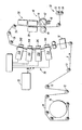
- the FIGURE is a simplified elevational view of a direct-to-sheet, continuous-web, phase-change ink printer.
- the FIGURE is a simplified elevational view of a direct-to-sheet, continuous-web, phase-change ink printer.
- a set of rolls 12 controls the tension of the unwinding web as the web moves through a path.
- a preheater 18 which brings the web to an initial predetermined temperature.
- the preheater 18 can rely on contact, radiant, conductive, or convective heat to bring the web W to a target preheat temperature, in one practical embodiment, of about 30°C to about 70°C.
- the web W moves through a printing station 20 including a series of printheads 21A, 21 B, 21C, and 21 D, each printhead effectively extending across the width of the web and being able to place ink of one primary color directly (i.e., without use of an intermediate or offset member) onto the moving web.
- a printing station 20 including a series of printheads 21A, 21 B, 21C, and 21 D, each printhead effectively extending across the width of the web and being able to place ink of one primary color directly (i.e., without use of an intermediate or offset member) onto the moving web.
- each of the four primary-color images placed on overlapping areas on the web W combine to form a full-color image, based on the image data sent to each printhead through image path 22.
- each primary color there may be provided multiple printheads for each primary color; the printheads can each be formed into a single linear array; the function of each color printhead can be divided among multiple distinct printheads located at different locations along the process direction; or the printheads or portions thereof can be mounted movably in a direction transverse to the process direction P, such as for spot-color applications.
- phase-change ink by which is meant that the ink is substantially solid at room temperature and substantially liquid when initially jetted onto the web W.
- phase-change inks are typically heated to about 100°C to 140°C, and thus in liquid phase, upon being jetted onto the web W. Generally speaking, the liquid ink cools down quickly upon hitting the web W.
- each primary color printhead is a backing member 24A, 24B, 24C, 24D, typically in the form of a bar or roll, which is arranged substantially opposite the printhead on the other side of web W.
- Each backing member is used to position the web W so that the gap between the printhead and the sheet stays at a known, constant distance.
- Each backing member can be controlled to cause the adjacent portion of the web to reach a predetermined "ink-receiving" temperature, in one practical embodiment, of about 40°C to about 60°C.
- each backing member can include heating elements, cavities for the flow of liquids therethrough, etc.; alternatively, the "member" can be in the form of a flow of air or other gas against or near a portion of the web W.
- the temperature of the web As the partially-imaged web moves to receive inks of various colors throughout the printing station 20 it is required that the temperature of the web be maintained to within a given range. Ink is jetted at a temperature typically significantly higher than the receiving web's temperature and thus will heat the surrounding paper (or whatever substance the web W is made of). Therefore the members in contact with or near the web in zone 20 must be adjusted so that that the desired web temperature is maintained. For example, although the backing members will have an effect on the web temperature, the air temperature and air flow rate behind and in front of the web will also impact the web temperature and thus must be considered when controlling the web temperature, and thus the web temperature could be affected by utilizing air blowers or fans behind the web in printing station 20.
- the web temperature is kept substantially uniform for the jetting of all inks from printheads in the printing zone 20.
- This uniformity is valuable for maintaining image quality, and particularly valuable for maintaining constant ink lateral spread (i.e., across the width of web W, such as perpendicular to process direction P) and constant ink penetration of the web.
- this web temperature uniformity may be achieved by preheating the web and using uncontrolled backer members, and/or by controlling the different backer members 24A, 24B, 24C, 24D to different temperatures to keep the substrate temperature substantially constant throughout the printing station.
- Temperature sensors (not shown) associated with the web W may be used with a control system to achieve this purpose, as well as systems for measuring or inferring (from the image data, for example) how much ink of a given primary color from a printhead is being applied to the web W at a given time.
- the various backer members can be controlled individually, using input data from the printhead adjacent thereto, as well as from other printheads in the printing station.
- the midheater 30 can use contact, radiant, conductive, and/or convective heat to bring the web W to the target temperature.
- the midheater 30 brings the ink placed on the web to a temperature suitable for desired properties when the ink on the web is sent through the spreader 40.
- a useful range for a target temperature for the midheater is about 35°C to about 80°C.
- the midheater 30 has the effect of equalizing the ink and substrate temperatures to within about 15°C of each other. Lower ink temperature gives less line spread while higher ink temperature causes show-through (visibility of the image from the other side of the print).
- the midheater 30 adjusts substrate and ink temperatures to 0°C to 20°C above the temperature of the spreader, which will be described below.
- a "spreader" 40 that applies a predetermined pressure, and in some implementations, heat, to the web W.
- the function of the spreader 40 is to take what are essentially isolated droplets of ink on web W and smear them out to make a continuous layer by pressure, and, in one embodiment, heat, so that spaces between adjacent drops are filled and image solids become uniform.
- the spreader 40 may also improve image permanence by increasing ink layer cohesion and/or increasing the ink-web adhesion.
- the spreader 40 includes rolls, such as image-side roll 42 and pressure roll 44, that apply heat and pressure to the web W. Either roll can include heat elements such as 46 to bring the web W to a temperature in a range from about 35°C to about 80°C.
- the roll temperature in spreader 40 is maintained at about 55°C; generally, a lower roll temperature gives less line spread while a higher temperature causes imperfections in the gloss. A roll temperature higher than about 57°C causes ink to offset to the roll.
- the nip pressure is set in a range of about 500 to about 2000 psi lbs/side. Lower nip pressure gives less line spread while higher may reduce pressure roll life.
- the spreader 40 can also include a cleaning/oiling station 48 associated with image-side roll 42, suitable for cleaning and/or applying a layer of some lubricant or other material to the roll surface.
- a cleaning/oiling station 48 associated with image-side roll 42, suitable for cleaning and/or applying a layer of some lubricant or other material to the roll surface.
- Such a station coats the surface of the spreader roll with a lubricant such as amino silicone oil having viscosity of about 10-200 centipoises. Only small amounts of oil are required and the oil carry out by web W is only about 1-10 mg per A4 size page.
- the midheater 30 and spreader 40 can be combined within a single unit, with their respective functions occurring relative to the same portion of web W simultaneously.
- the printer in this embodiment includes a "glosser” 50, whose function is to change the gloss of the image (such a glosser can be considered an "option" in a practical implementation).
- the glosser 50 applies a predetermined combination of temperature and pressure, to obtain a desired amount of gloss on the ink that has just been spread by spreader 40.
- the glosser roll surface may have a texture that the user desires to impress on the ink surface.
- the glosser 50 includes two rolls (image-side roll 52 and pressure roll 54) forming a nip through which the web W passes.
- the controlled temperature at spreader 40 is about 35°C to about 80°C and the controlled temperature at glosser 50 is about 30°C to about 70°C.
- the image side roll 42 or 52 contacting the inked side of the web is typically reasonably hard, such as being made of anodized aluminum.
- a relatively softer roll is used, with a durometer anywhere from about 50D to about 65D, with elastic modulii from about 65 MPa to about 115 MPa, and may include a thin elastomer overcoat.
- elastomeric or rubbery pressure rolls of one or more layers, with effective elastic modulii from about 50 MPa to about 200 MPa can be provided.
- Typical pressure against the web W for the roll pairs in each of the spreader 40 and glosser 50 is about 500 to about 2000 lbs/square inch. Adjustment of the pressure is advisable with ink formulations that are soft enough that high pressure would cause excessive spreading. It is also possible to provide an image-side roll 52 in glosser 50 with different surface textures so that, with higher temperature and pressure, texture can be impressed into the ink surface.
- the printed web can be imaged on the other side, and then cut into pages, such as for binding (not shown).
- printing on a substantially continuous web is shown in the embodiment, the claimed invention can be applied to a cut-sheet system as well. Different preheat, midheat and spreader temperature setpoints can be selected for different types and weights of web media.
Landscapes
- Health & Medical Sciences (AREA)
- General Health & Medical Sciences (AREA)
- Toxicology (AREA)
- Ink Jet (AREA)
- Ink Jet Recording Methods And Recording Media Thereof (AREA)
- Inks, Pencil-Leads, Or Crayons (AREA)
- Coloring (AREA)
Claims (13)
- Druckvorrichtung, umfassend:Einrichtungen (12, 26) zum Bewegen eines Substrates entlang eines Weges undeine Druckstation (20), die entlang des Weges angeordnet ist, wobei die Druckstation wenigstens einen Druckkopf (21) zum Aufbringen von Phasenwechseltinte auf das Substrat und ein Stützelement (24) umfasst, das auf einer gegenüberliegenden Seite des Substrates im wesentlichen gegenüber des Druckkopfes (21) angeordnet ist, wobei das Stützelement (24) bewirkt, dass das Substrat einen vorbestimmten Tintenaufnahme-Temperaturbereich erreicht,dadurch gekennzeichnet, dassdas Stützelement das Substrat auf eine Tintenaufnahme-Temperatur in einem Bereich von etwa 40°C bis etwa 60°C bringt, wobei die Phasenwechseltinte eine Temperatur von etwa 100°C bis etwa 140°C hat, wenn sie auf das Substrat aufgebracht wird.
- Vorrichtung nach Anspruch 1, bei der das Substrat eine im wesentlichen kontinuierliche Bahn ist.
- Vorrichtung nach Anspruch 1, bei der das Substrat im wesentlichen Papier umfasst.
- Vorrichtung nach Anspruch 1, weiterhin umfassend eine Vorheizeinrichtung (18), die stromaufwärts der Druckstation entlang des Weges angeordnet ist, um das Substrat auf eine vorbestimmte Vorwärmtemperatur zu bringen.
- Vorrichtung nach Anspruch 4, bei der die Vorheizeinrichtung (18) das Substrat auf eine Vorwärmtemperatur in einem Bereich von etwa 30°C bis etwa 70°C bringt.
- Vorrichtung nach Anspruch 1, weiterhin umfassend eine Mittelheizeinrichtung (30), die stromabwärts der Druckstation (20) entlang des Weges angeordnet ist, wobei die Mittelheizeinrichtung die Wirkung hat, die Tinten- und die Substrattemperatur innerhalb etwa 15°C aneinander anzugleichen.
- Vorrichtung nach Anspruch 1, weiterhin umfassend eine Mittelheizeinrichtung (30), die stromabwärts der Druckstation (20) entlang des Weges angeordnet ist, wobei die Mittelheizeinrichtung das Substrat auf eine Temperatur in einem Bereich von etwa 35°C bis etwa 80°C bringt.
- Vorrichtung nach Anspruch 7, weiterhin umfassend eine Verteileinrichtung (40), die stromabwärts der Mittelheizeinrichtung (30) entlang des Weges angeordnet ist, wobei die Verteileinrichtung (40) Druck auf das Substrat ausübt.
- Vorrichtung nach Anspruch 8, bei der die Verteileinrichtung (40) das Substrat auf eine Temperatur in einem Bereich von etwa 35°C bis etwa 80°C bringt.
- Vorrichtung nach Anspruch 8, bei der die Mittelheizeinrichtung (30) bewirkt, dass die Substrat- und die Tintentemperatur 0° bis 20° über der Temperatur der Verteileinrichtung (40) liegt.
- Vorrichtung nach Anspruch 9, weiterhin umfassend eine Glanzgraderzeugungseinrichtung (50), die stromabwärts der Verteileinrichtung (40) entlang des Weges angeordnet ist, wobei die Glanzgraderzeugungseinrichtung (50) einen Druck auf das Substrat ausübt.
- Vorrichtung nach Anspruch 11, bei der eine Temperatur, die mit der Verteileinrichtung assoziiert ist, etwa 35°C bis etwa 80°C beträgt und eine Temperatur, die mit der Glanzgraderzeugungseinrichtung assoziiert ist, etwa 30°C bis etwa 70°C beträgt.
- Vorrichtung nach Anspruch 12, bei der die Verteileinrichtung (50) dazu eingerichtet ist, auf das Substrat einen Druck von nicht weniger als 500 psi auszuüben.
Applications Claiming Priority (1)
| Application Number | Priority Date | Filing Date | Title |
|---|---|---|---|
| US11/773,549 US7828423B2 (en) | 2007-07-05 | 2007-07-05 | Ink-jet printer using phase-change ink printing on a continuous web |
Publications (2)
| Publication Number | Publication Date |
|---|---|
| EP2011659A1 EP2011659A1 (de) | 2009-01-07 |
| EP2011659B1 true EP2011659B1 (de) | 2013-04-17 |
Family
ID=39734163
Family Applications (1)
| Application Number | Title | Priority Date | Filing Date |
|---|---|---|---|
| EP08159751.0A Ceased EP2011659B1 (de) | 2007-07-05 | 2008-07-04 | Tintenstrahldrucker mit Phasenwechsel-Tintendruck auf einem durchgehenden Netz |
Country Status (5)
| Country | Link |
|---|---|
| US (1) | US7828423B2 (de) |
| EP (1) | EP2011659B1 (de) |
| JP (1) | JP4898747B2 (de) |
| KR (1) | KR101218565B1 (de) |
| CN (1) | CN101337458B (de) |
Families Citing this family (30)
| Publication number | Priority date | Publication date | Assignee | Title |
|---|---|---|---|---|
| US20100259573A1 (en) * | 2009-04-13 | 2010-10-14 | Xerox Corporation | Method of controlling marking on continuous web print media |
| US7931363B2 (en) * | 2009-04-28 | 2011-04-26 | Xerox Corporation | Open loop oil delivery system |
| US8384748B2 (en) * | 2009-07-29 | 2013-02-26 | Xerox Corporation | Fabrication of improved aluminum rollers with low adhesion and ultra/super hydrophobicity and/or oleophobicity by electrospinning technique in solid ink-jet marking |
| US8192005B2 (en) * | 2009-07-29 | 2012-06-05 | Xerox Corporation | Rollers for phase-change ink printing |
| US8162469B2 (en) * | 2009-09-17 | 2012-04-24 | Xerox Corporation | Method for achieving uniform media temperature and size throughout the pre-heat zone |
| US8220918B2 (en) * | 2009-12-21 | 2012-07-17 | Xerox Corporation | Spreader module for duplex continuous feed imaging devices |
| US8340546B2 (en) | 2010-04-06 | 2012-12-25 | Xerox Corporation | Dual function charging device and charge patterning device cleaner |
| US8303103B2 (en) | 2010-05-28 | 2012-11-06 | Xerox Corporation | Peak position drum maintenance unit for a printing device |
| US8369768B2 (en) | 2010-06-17 | 2013-02-05 | Xerox Corporation | Cleaning blade parameter adjustment system |
| US8478178B2 (en) | 2010-08-12 | 2013-07-02 | Xerox Corporation | Fixing devices for fixing marking material to a web with contact pre-heating of web and marking material and methods of fixing marking material to a web |
| US8422926B2 (en) | 2010-08-12 | 2013-04-16 | Xerox Corporation | Fixing devices including low-viscosity release agent applicator system and methods of fixing marking material to substrates |
| US8897683B2 (en) | 2010-08-12 | 2014-11-25 | Xerox Corporation | Fixing systems including image conditioner and image pre-heater and methods of fixing marking material to substrates |
| US20120039649A1 (en) * | 2010-08-12 | 2012-02-16 | Xerox Corporation | Fixing apparatus, systems, and methods for printing |
| US8265536B2 (en) | 2010-08-12 | 2012-09-11 | Xerox Corporation | Fixing systems including contact pre-heater and methods for fixing marking material to substrates |
| US8280287B2 (en) | 2010-08-12 | 2012-10-02 | Xerox Corporation | Multi-stage fixing systems, printing apparatuses and methods of fixing marking material to substrates |
| US8660682B2 (en) * | 2010-11-22 | 2014-02-25 | Honeywell Asca Inc. | Air wipe and sheet guide temperature control on paper and continuous web scanners |
| JP5811101B2 (ja) * | 2010-12-10 | 2015-11-11 | コニカミノルタ株式会社 | インクジェット記録装置 |
| US8740325B2 (en) | 2010-12-13 | 2014-06-03 | Xerox Corporation | Method for printing in a printer having an inoperable ink reservoir |
| US8666188B2 (en) | 2011-03-23 | 2014-03-04 | Xerox Corporation | Identifying edges of web media using textural contrast between web media and backer roll |
| US8702186B2 (en) * | 2012-01-26 | 2014-04-22 | Xerox Corporation | Method and apparatus for ink recirculation |
| US9676202B2 (en) * | 2012-05-09 | 2017-06-13 | Xerox Corporation | System and method for detecting defects in an inkjet printer |
| US8668318B2 (en) | 2012-07-26 | 2014-03-11 | Xerox Corporation | System and method for spreading ink on a media web |
| US8740337B2 (en) * | 2012-07-31 | 2014-06-03 | Eastman Kodak Company | Wrinkle elimination for solid inkjet web printer |
| US8827439B2 (en) * | 2012-08-20 | 2014-09-09 | Xerox Corporation | Self-cleaning media perforator |
| JP5978853B2 (ja) | 2012-08-21 | 2016-08-24 | セイコーエプソン株式会社 | 液体噴射装置 |
| US9027477B2 (en) * | 2013-03-28 | 2015-05-12 | Xerox Corporation | Wrinkle detection in continuous feed printers |
| US9010925B2 (en) | 2013-07-15 | 2015-04-21 | Xerox Corporation | Air film support device for an inkjet printer |
| US9403358B1 (en) * | 2015-04-17 | 2016-08-02 | Xerox Corporation | System and method for forming hydrophobic structures in a hydrophilic print medium |
| KR102444364B1 (ko) * | 2019-03-26 | 2022-09-16 | 주식회사 아르볼소피아 | 표면 처리 기능을 포함하는 프린팅 방법 및 상기 프린팅 방법에 의해 프린팅된 소재 |
| KR102261210B1 (ko) * | 2019-03-26 | 2021-06-04 | 주식회사 아르볼소피아 | 표면 처리 기능을 포함하는 프린팅 장치 |
Family Cites Families (20)
| Publication number | Priority date | Publication date | Assignee | Title |
|---|---|---|---|---|
| JPH0226747A (ja) | 1988-07-18 | 1990-01-29 | Brother Ind Ltd | ホットメルト式インクジェットプリンタ |
| US5287123A (en) | 1992-05-01 | 1994-02-15 | Hewlett-Packard Company | Preheat roller for thermal ink-jet printer |
| US5406315A (en) | 1992-07-31 | 1995-04-11 | Hewlett-Packard Company | Method and system for remote-sensing ink temperature and melt-on-demand control for a hot melt ink jet printer |
| US5502476A (en) * | 1992-11-25 | 1996-03-26 | Tektronix, Inc. | Method and apparatus for controlling phase-change ink temperature during a transfer printing process |
| JP2936377B2 (ja) * | 1992-11-25 | 1999-08-23 | テクトロニクス・インコーポレイテッド | 画像形成方法 |
| US5389958A (en) | 1992-11-25 | 1995-02-14 | Tektronix, Inc. | Imaging process |
| JPH06220781A (ja) | 1993-01-28 | 1994-08-09 | Kanebo Ltd | 捺染方法および装置 |
| US5742315A (en) * | 1995-09-05 | 1998-04-21 | Xerox Corporation | Segmented flexible heater for drying a printed image |
| US5793398A (en) | 1995-11-29 | 1998-08-11 | Levi Strauss & Co. | Hot melt ink jet shademarking system for use with automatic fabric spreading apparatus |
| US5777650A (en) | 1996-11-06 | 1998-07-07 | Tektronix, Inc. | Pressure roller |
| JPH1120141A (ja) * | 1997-07-02 | 1999-01-26 | Brother Ind Ltd | ホットメルトインクジェットプリンタ |
| US6196675B1 (en) | 1998-02-25 | 2001-03-06 | Xerox Corporation | Apparatus and method for image fusing |
| US6113231A (en) | 1998-02-25 | 2000-09-05 | Xerox Corporation | Phase change ink printing architecture suitable for high speed imaging |
| JP2000141621A (ja) * | 1998-11-10 | 2000-05-23 | Brother Ind Ltd | 画像形成装置 |
| JP2000296607A (ja) * | 1999-04-16 | 2000-10-24 | Mutoh Ind Ltd | インクジェットプリンタ |
| US6361230B1 (en) | 1999-09-17 | 2002-03-26 | Macdermid Acumen, Inc. | Printing zone specially adapted for textile printing media |
| US6485140B1 (en) | 1999-11-30 | 2002-11-26 | Macdermid Acumen, Inc. | Auxiliary underside media dryer |
| US6494570B1 (en) | 2001-12-04 | 2002-12-17 | Xerox Corporation | Controlling gloss in an offset ink jet printer |
| US6932526B2 (en) | 2003-11-21 | 2005-08-23 | Xerox Corporation | Multi-stage pre-transfer substrate heating assembly |
| DE602005013480D1 (de) * | 2004-12-29 | 2009-05-07 | Oce Tech Bv | Temperatursteuerungssystem für Blattstützplatte eines Druckers |
-
2007
- 2007-07-05 US US11/773,549 patent/US7828423B2/en active Active
-
2008
- 2008-06-30 JP JP2008169721A patent/JP4898747B2/ja not_active Expired - Fee Related
- 2008-07-04 CN CN2008101282635A patent/CN101337458B/zh not_active Expired - Fee Related
- 2008-07-04 KR KR1020080064756A patent/KR101218565B1/ko not_active Expired - Fee Related
- 2008-07-04 EP EP08159751.0A patent/EP2011659B1/de not_active Ceased
Also Published As
| Publication number | Publication date |
|---|---|
| JP4898747B2 (ja) | 2012-03-21 |
| US20090009573A1 (en) | 2009-01-08 |
| CN101337458A (zh) | 2009-01-07 |
| CN101337458B (zh) | 2013-07-17 |
| KR101218565B1 (ko) | 2013-01-07 |
| JP2009012467A (ja) | 2009-01-22 |
| US7828423B2 (en) | 2010-11-09 |
| EP2011659A1 (de) | 2009-01-07 |
| KR20090004737A (ko) | 2009-01-12 |
Similar Documents
| Publication | Publication Date | Title |
|---|---|---|
| EP2011659B1 (de) | Tintenstrahldrucker mit Phasenwechsel-Tintendruck auf einem durchgehenden Netz | |
| US8152288B2 (en) | Method and system for achieving uniform ink and web temperatures for spreading | |
| US20090141110A1 (en) | Ink-jet printer using phase-change ink for direct on paper printing | |
| EP0938974B1 (de) | System zum Drucken mit Phasenaustauschtinte zur Bilderzeugung mit hoher Geschwindigkeit | |
| US8262186B2 (en) | Pre-leveler cooling device for continuous feed imaging devices | |
| US8350879B2 (en) | Non-contact heating of solid ink prints after ink fixing | |
| US7874664B2 (en) | Electrically conductive pressure roll surfaces for phase-change ink-jet printer for direct on paper printing | |
| KR102165979B1 (ko) | 잉크젯 프린터용 모듈형 프린트 바 조립체 | |
| EP2338816B1 (de) | Medieninversionssystem für einen Drucker mit kontinuierlichen Bahnen | |
| US8162469B2 (en) | Method for achieving uniform media temperature and size throughout the pre-heat zone | |
| US8419160B2 (en) | Method and system for operating a printhead to compensate for failed inkjets | |
| US9682573B2 (en) | Printer having edge control apparatus for web media | |
| US8220918B2 (en) | Spreader module for duplex continuous feed imaging devices | |
| US20140125730A1 (en) | Method for Printing Phase Change Ink onto Porous Media | |
| US8899738B2 (en) | Pressure roller containing a volume of fluid | |
| US9434155B1 (en) | Method and system for printhead alignment based on print medium width | |
| JPH11320865A (ja) | インク・ジェット・プリンタ用オフセット・プリント方法及びプリント装置 | |
| US8668318B2 (en) | System and method for spreading ink on a media web | |
| US8240813B2 (en) | Directed flow drip bib for an inkjet printhead | |
| US9085137B2 (en) | Method and apparatus to reduce settling of magnetic particles in magnetic ink | |
| US7845783B2 (en) | Pressure roller two-layer coating for phase-change ink-jet printer for direct on paper printing | |
| US8540357B2 (en) | Dithered printing of clear ink to reduce rub and offset | |
| EP0938975B1 (de) | Apparat und Verfahren zum Schmelzfixieren von Bildern | |
| JP2025001188A (ja) | 印刷装置、印刷方法、及び印刷システム | |
| JPH11334057A (ja) | インク・ジェット・プリンタ及びそのオフセット・プリント方法 |
Legal Events
| Date | Code | Title | Description |
|---|---|---|---|
| PUAI | Public reference made under article 153(3) epc to a published international application that has entered the european phase |
Free format text: ORIGINAL CODE: 0009012 |
|
| AK | Designated contracting states |
Kind code of ref document: A1 Designated state(s): AT BE BG CH CY CZ DE DK EE ES FI FR GB GR HR HU IE IS IT LI LT LU LV MC MT NL NO PL PT RO SE SI SK TR |
|
| AX | Request for extension of the european patent |
Extension state: AL BA MK RS |
|
| 17P | Request for examination filed |
Effective date: 20090707 |
|
| 17Q | First examination report despatched |
Effective date: 20090731 |
|
| AKX | Designation fees paid |
Designated state(s): DE FR GB |
|
| REG | Reference to a national code |
Ref country code: DE Ref legal event code: R079 Ref document number: 602008023843 Country of ref document: DE Free format text: PREVIOUS MAIN CLASS: B41J0011000000 Ipc: B41J0011020000 |
|
| RIC1 | Information provided on ipc code assigned before grant |
Ipc: B41J 11/00 20060101ALI20121031BHEP Ipc: B41J 11/02 20060101AFI20121031BHEP Ipc: B41J 2/175 20060101ALI20121031BHEP |
|
| GRAP | Despatch of communication of intention to grant a patent |
Free format text: ORIGINAL CODE: EPIDOSNIGR1 |
|
| GRAS | Grant fee paid |
Free format text: ORIGINAL CODE: EPIDOSNIGR3 |
|
| GRAA | (expected) grant |
Free format text: ORIGINAL CODE: 0009210 |
|
| AK | Designated contracting states |
Kind code of ref document: B1 Designated state(s): DE FR GB |
|
| REG | Reference to a national code |
Ref country code: GB Ref legal event code: FG4D |
|
| REG | Reference to a national code |
Ref country code: DE Ref legal event code: R096 Ref document number: 602008023843 Country of ref document: DE Effective date: 20130613 |
|
| PLBE | No opposition filed within time limit |
Free format text: ORIGINAL CODE: 0009261 |
|
| STAA | Information on the status of an ep patent application or granted ep patent |
Free format text: STATUS: NO OPPOSITION FILED WITHIN TIME LIMIT |
|
| 26N | No opposition filed |
Effective date: 20140120 |
|
| REG | Reference to a national code |
Ref country code: DE Ref legal event code: R097 Ref document number: 602008023843 Country of ref document: DE Effective date: 20140120 |
|
| REG | Reference to a national code |
Ref country code: FR Ref legal event code: PLFP Year of fee payment: 9 |
|
| REG | Reference to a national code |
Ref country code: FR Ref legal event code: PLFP Year of fee payment: 10 |
|
| REG | Reference to a national code |
Ref country code: FR Ref legal event code: PLFP Year of fee payment: 11 |
|
| PGFP | Annual fee paid to national office [announced via postgrant information from national office to epo] |
Ref country code: FR Payment date: 20200623 Year of fee payment: 13 |
|
| PGFP | Annual fee paid to national office [announced via postgrant information from national office to epo] |
Ref country code: GB Payment date: 20200624 Year of fee payment: 13 |
|
| PGFP | Annual fee paid to national office [announced via postgrant information from national office to epo] |
Ref country code: DE Payment date: 20200622 Year of fee payment: 13 |
|
| REG | Reference to a national code |
Ref country code: DE Ref legal event code: R119 Ref document number: 602008023843 Country of ref document: DE |
|
| GBPC | Gb: european patent ceased through non-payment of renewal fee |
Effective date: 20210704 |
|
| PG25 | Lapsed in a contracting state [announced via postgrant information from national office to epo] |
Ref country code: GB Free format text: LAPSE BECAUSE OF NON-PAYMENT OF DUE FEES Effective date: 20210704 Ref country code: DE Free format text: LAPSE BECAUSE OF NON-PAYMENT OF DUE FEES Effective date: 20220201 |
|
| PG25 | Lapsed in a contracting state [announced via postgrant information from national office to epo] |
Ref country code: FR Free format text: LAPSE BECAUSE OF NON-PAYMENT OF DUE FEES Effective date: 20210731 |