EP2010819B1 - Light emitting diode packages - Google Patents
Light emitting diode packages Download PDFInfo
- Publication number
- EP2010819B1 EP2010819B1 EP07760470.0A EP07760470A EP2010819B1 EP 2010819 B1 EP2010819 B1 EP 2010819B1 EP 07760470 A EP07760470 A EP 07760470A EP 2010819 B1 EP2010819 B1 EP 2010819B1
- Authority
- EP
- European Patent Office
- Prior art keywords
- leds
- package
- led
- led lighting
- arrays
- Prior art date
- Legal status (The legal status is an assumption and is not a legal conclusion. Google has not performed a legal analysis and makes no representation as to the accuracy of the status listed.)
- Active
Links
Images


Classifications
-
- F—MECHANICAL ENGINEERING; LIGHTING; HEATING; WEAPONS; BLASTING
- F21—LIGHTING
- F21K—NON-ELECTRIC LIGHT SOURCES USING LUMINESCENCE; LIGHT SOURCES USING ELECTROCHEMILUMINESCENCE; LIGHT SOURCES USING CHARGES OF COMBUSTIBLE MATERIAL; LIGHT SOURCES USING SEMICONDUCTOR DEVICES AS LIGHT-GENERATING ELEMENTS; LIGHT SOURCES NOT OTHERWISE PROVIDED FOR
- F21K9/00—Light sources using semiconductor devices as light-generating elements, e.g. using light-emitting diodes [LED] or lasers
-
- F—MECHANICAL ENGINEERING; LIGHTING; HEATING; WEAPONS; BLASTING
- F21—LIGHTING
- F21V—FUNCTIONAL FEATURES OR DETAILS OF LIGHTING DEVICES OR SYSTEMS THEREOF; STRUCTURAL COMBINATIONS OF LIGHTING DEVICES WITH OTHER ARTICLES, NOT OTHERWISE PROVIDED FOR
- F21V29/00—Protecting lighting devices from thermal damage; Cooling or heating arrangements specially adapted for lighting devices or systems
- F21V29/50—Cooling arrangements
- F21V29/70—Cooling arrangements characterised by passive heat-dissipating elements, e.g. heat-sinks
-
- H—ELECTRICITY
- H05—ELECTRIC TECHNIQUES NOT OTHERWISE PROVIDED FOR
- H05B—ELECTRIC HEATING; ELECTRIC LIGHT SOURCES NOT OTHERWISE PROVIDED FOR; CIRCUIT ARRANGEMENTS FOR ELECTRIC LIGHT SOURCES, IN GENERAL
- H05B45/00—Circuit arrangements for operating light-emitting diodes [LED]
- H05B45/10—Controlling the intensity of the light
- H05B45/14—Controlling the intensity of the light using electrical feedback from LEDs or from LED modules
-
- H—ELECTRICITY
- H05—ELECTRIC TECHNIQUES NOT OTHERWISE PROVIDED FOR
- H05B—ELECTRIC HEATING; ELECTRIC LIGHT SOURCES NOT OTHERWISE PROVIDED FOR; CIRCUIT ARRANGEMENTS FOR ELECTRIC LIGHT SOURCES, IN GENERAL
- H05B45/00—Circuit arrangements for operating light-emitting diodes [LED]
- H05B45/40—Details of LED load circuits
-
- F—MECHANICAL ENGINEERING; LIGHTING; HEATING; WEAPONS; BLASTING
- F21—LIGHTING
- F21Y—INDEXING SCHEME ASSOCIATED WITH SUBCLASSES F21K, F21L, F21S and F21V, RELATING TO THE FORM OR THE KIND OF THE LIGHT SOURCES OR OF THE COLOUR OF THE LIGHT EMITTED
- F21Y2103/00—Elongate light sources, e.g. fluorescent tubes
- F21Y2103/10—Elongate light sources, e.g. fluorescent tubes comprising a linear array of point-like light-generating elements
-
- F—MECHANICAL ENGINEERING; LIGHTING; HEATING; WEAPONS; BLASTING
- F21—LIGHTING
- F21Y—INDEXING SCHEME ASSOCIATED WITH SUBCLASSES F21K, F21L, F21S and F21V, RELATING TO THE FORM OR THE KIND OF THE LIGHT SOURCES OR OF THE COLOUR OF THE LIGHT EMITTED
- F21Y2105/00—Planar light sources
- F21Y2105/10—Planar light sources comprising a two-dimensional [2D] array of point-like light-generating elements
-
- F—MECHANICAL ENGINEERING; LIGHTING; HEATING; WEAPONS; BLASTING
- F21—LIGHTING
- F21Y—INDEXING SCHEME ASSOCIATED WITH SUBCLASSES F21K, F21L, F21S and F21V, RELATING TO THE FORM OR THE KIND OF THE LIGHT SOURCES OR OF THE COLOUR OF THE LIGHT EMITTED
- F21Y2115/00—Light-generating elements of semiconductor light sources
- F21Y2115/10—Light-emitting diodes [LED]
Definitions
- the present invention relates to a package of light emitting diodes according to the preamble of claim 1 which is known from US 2006/0061539 A1 .
- a common prior art LED mounting arrangement results in a substantial portion of the light output going upwardly in the direction of a normal to the top surface of a semiconductor photonic chip 12 as seen in Fig. IB.
- the semiconductor photonic chip 12 is mounted on a substrate 14 which is in turn mounted on a bonding pad 16.
- the chip 12 is encapsulated beneath an optical lens 18 which focuses the light emitted by the chip 12.
- Fig. IB shows a side view of LED 10 with a plurality of light rays relative to a normal, N, to the top surface of chip 12 illustrating the light emitted by chip 12 as it passes out of lens 18.
- LED 10 is an XLampTM 7090 from Cree, Incorporated.
- Fig, 1C shows an illustrative plot of the light emitted by LED 10 with the y-axis representing the intensity, I, and the x-axis representing the angle, 0, of the emitted light with respect to the normal, N, of Fig, IB.
- a substantial portion of the light emitted from the LED is along or near the normal, N. Conversely, only a small percentage is emitted sideways.
- Angle a the angle of intensity, is equal to 2*0.
- the angle of intensity revolves around the normal, N, forming a cone of light.
- a photonic chip may be specifically manufactured to primarily emit white light. Some of these photonic chips may emit a disproportionate amount of yellow light near the edges of the cone of light whereas light emitted at other angles within the angle of intensity emit primarily white light. When this emitted light strikes a diffuser, such as back lighting a curtain or a shield covering an LED light package, for example, yellow rings around a concentration of white light may be visible to the human eye, causing a degradation of color uniformity.
- LED 10 when LED 10 is powered on, heat from LED 10 collects along the bottom surface 15 of bonding pad 16. In general, heat radiates from the bottom of photonic chip 12.
- an LED such as LED 10 may be driven by approximately 350 mAmps and expend 1 Watt of power where approximately 90% of the expended power is in the form of heat.
- a conventional active technique includes employing a fan to blow cooler air onto the back surface of LED 10.
- Several disadvantages of this conventional technique include its cost, its unaesthetic appearance, and the production of fan noise.
- One conventional passive technique includes an aluminum panel with large aluminum extrusions emanating from an outer edge of a light fixture. At least a few of the failings of this approach include added cost for materials composing the extrusions, added weight, and limited heat dissipation due to a build up of air pressure resulting from the heated air being trapped by the extrusions.
- the present invention recognizes the desirability of both increasing brightness and passively controlling heat dissipation of heat generated by powered LEDs and addresses a variety of techniques for addressing such ends. Further, the present invention recognizes that material cost, light weight, and ease of manufacture with a small number of parts are also highly desirable and seeks to address such ends as well.
- Some exemplary lighting applications include lighting a horizontal surface, wall washing, back lighting a diffuser, and the like. Each of these lighting applications may have different requirements with respect to brightness levels, lighting patterns, and color uniformity. As multiple LEDs such a LED 10 are arranged to address varied requirements of different lighting applications, the brightness of the collective emitted light and the amount of heat generated per area varies with the arrangement. For example, a particular lighting application may require a high brightness level. To meet the high brightness requirement of the particular lighting application, more LEDs may be arranged closer together in the same predefined area as a lighting application requiring less brightness. However, the closer together LEDs are placed, the more heat is generated in the concentrated area containing the LEDs.
- the present invention recognizes that an arrangement of LEDs should balance factors such as color uniformity, heat dissipation, material cost, brightness, and the like.
- the present approach includes a backing of thermally conductive material and two or more arrays of LEDs attached to a printed circuit board (PCB).
- PCB printed circuit board
- array of LEDs as used herein means a module of one or more LEDs in various configurations and arrangements.
- the PCB is attached to the top surface of the backing and the two or more arrays of LEDs are separated by a selected distance to balance heat dissipation and color uniformity of the LEDs.
- Another aspect of the present invention includes a plurality of LEDs, a T-shaped bar composed of thermally conductive material, and a printed circuit board (PCB).
- the plurality of LEDS are attached to the PCB.
- the PCB is attached to the upper surface of the T-shaped bar to dissipate heat generated from the plurality of LEDs.
- Fig. 2A shows a top view of a 1 foot x 1 foot light emitting diode (LED) lighting package 200 in accordance with the present invention.
- the LED lighting package 200 includes a backing 210 of thermally conductive material such as aluminum.
- Backing 210 as shown in Fig. 2 is a planar sheet of aluminum with a thickness of approximately 1/16 inch.
- other backing constructs may provide additional heat dissipation properties and can be employed in similar arrangements as backing 210.
- the patent application entitled “Light Emitting Diode Lighting Package with Improved Heat Sink” concurrently filed with this application addresses additional backing structures and is incorporated by reference herein in its entirety.
- the LED lighting package 200 includes three columns of LEDs. Each column includes two printed circuit boards (PCBs) such as PCB 220A and 220B. On each PCB, five LEDs such as LED 10 are mounted and are electrically connected in serial with each other. Each PCB includes a positive voltage terminal and a negative voltage terminal (not shown). The negative voltage terminal of PCB 220A is electrically connected to the positive voltage terminal of PCB 220B so that the ten LEDs defining a column are electrically connected in serial.
- PCBs printed circuit boards
- each column of ten LEDs is electrically connected in parallel to its adjacent column by wires 230A-D, respectively.
- the backing 210 is preferably anodized with a white gloss to reflect the light emitted from the LEDs.
- the three column arrangement of LEDs as illustrated in Fig. 2 A seeks to balance heat dissipation for the LEDs, color uniformity, brightness, and cost in an advantageous manner.
- the LEDs are positioned in the vertical direction at equidistant spacing, v, and in the horizontal direction at equidistant spacing, d. The spacing is measured from the center of two adjacent LEDs.
- the exemplary measurements shown in Fig. 2A have the vertical equidistant spacing, v as approximately 1 inch.
- the vertical equidistant spacing, v is typically determined by the LED mounting arrangement such as the mounting arrangement shown in Fig. 1A .
- the horizontal equidistant spacing, d is approximately 3 inches. If the horizontal spacing is increased beyond approximately d, overall brightness will degrade due to the number of LEDs being able to fit in the 1 foot x 1 foot lighting package 200, thermal dissipation will level off, and color uniformity will degrade.
- LED lighting package 200 satisfies the brightness requirement while also providing color uniformity and effective heat dissipation at a reasonable cost. For example, when powering LED lighting package 200 under an ambient temperature of approximately 25° C, the temperature of backing 210 at steady state was approximately 55° C.
- Fig. 2B shows a top view of a 1 foot x 1 foot light emitted diode (LED) lighting package 240 in accordance with the present invention.
- LED lighting package 240 addresses those applications which have low brightness level requirements and, thus, need to primarily focus on addressing color uniformity.
- LED lighting package 240 positions the LEDs so that each of the LEDs are approximately equidistant from an adjacent LED in every direction. As shown in Fig. 2B , eleven LEDs are equally spaced distance, d, inches apart.
- d For example, in the 1 foot x 1 foot LED lighting package 240 which utilizes LED 10 having an angle of intensity of 100°, d equals approximately three inches. At distance, d, or closer, the intensity of primarily white light emitted from one LED absorbs the yellow light found at the edges of a cone of light emitted by an adjacent LED. Since the total number of LEDs in LED lighting package 240 is eleven, heat dissipation in a 1 foot x 1 foot frame is a non-issue. Consequently, d may be decreased and more LEDs may be added without affecting color uniformity until the heat dissipation capacity of backing 210 is maximized.
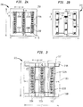
- Fig. 3 shows a top view of a 1 foot x 1 foot LED lighting package 300 employing an alternative backing arrangement 305 in accordance with the present invention.
- Backing arrangement 305 is in the form of a ladder structure.
- the ladder structure is composed of strips of thermally conductive material such as aluminum and preferably anodized with a white gloss.
- the ladder structure includes an upper member 310A and a lower member 310B attached to cross members 315A-315C.
- the cross members 315A-315C as shown in this exemplary embodiment are approximately 1.5 inches wide, 1 foot long, and 1/16 inch thick and are spaced z or approximately 1.6 inches apart.
- Cross members 315A-315C are attached to members 310A-310B and separated by free space.
- PCBs such as PCBs 320A and 320B containing an array of five LEDs are attached to the cross members 315A-315C.
- the combination of cross member 315C with PCBs 320A and 320B compose LED module 317.
- the vertical equidistant spacing, v, in this exemplary embodiment is approximately 1 inch.
- the horizontal equidistant spacing, d, in this exemplary embodiment is approximately 2.75 inches.
- the edge distance, e, as shown in Fig. 3 is approximately 3 1/4 inches.
- the LED lighting package 300 may now achieve higher brightness levels than LED lighting package 200 with the same heat dissipation because the LED arrays can be positioned closer. Furthermore, since the edge distance, e, is greater than the horizontal distance, d, an additional column of LEDs may be added, further increasing the brightness as will be discussed further in connection with Fig. 5C .
- the ladder structure is shown as strips of thermally conductive materially attached to support members, the present invention contemplates alternative techniques of forming a ladder structure such as by stamping out space gaps from a planar backing such as backing 210.
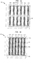
- Figs. 4A and 4B are top views illustrating aspects of two 2 feet x 2 feet LED lighting packages.
- Fig. 4A shows a 2 feet x 2 feet LED lighting package 400.
- LED lighting package 400 comprises six columns 405A-405F of twenty LEDs. Each of the LEDs in a particular column is electrically connected in serial. Each column of LEDs is electrically connected in parallel.
- LED lighting package 400 is composed of four 1 foot x 1 foot LED lighting packages 200 fixedly attached to each other with modified wiring to maintain the parallel electrical connections between columns 405A-405F.
- the horizontal and vertical spacing of LED lighting package 400 is the same as Fig. 2A .
- LED lighting package 400 may be alternatively constructed utilizing a planar sheet of thermally conductive material for backing 403 and the columns 405A-45F may be fixedly attached to the planar sheet.
- Fig. 4B shows a 2 feet x 2 feet LED lighting package 410.
- LED lighting package 410 comprises a ladder structure 415.
- the ladder structure 415 includes an upper member 420A, an optional middle member 420B, and a lower member 420C.
- the ladder structure 415 also includes cross members 417A-417F where each member is fixedly attached to members 420A-420C.
- Each cross member has a column of four PCBs with each PCB having five LEDs mounted thereon.
- the horizontal and vertical spacing of LED lighting package 410 is the same as Fig. 3 .
- Members 420A-420B and 417A-417F are constructed from a thermally conductive material such as aluminum which is preferably anodized with a white gloss.
- LED lighting packages are illustrative and exemplary.
- Fig. 4C is a perspective view of an exemplary backlight lighting application 422 employing six LED lighting packages 425A-425F.
- LED lighting packages 425A-425F may suitably be similar to LED lighting packages 200, 240, 300, 400, and 410 and the choice of which LED lighting package to deploy in the exemplary lighting application 422 depends on the brightness level required to illuminate curtain 427, a distance between lighting packages and curtain 427, and aesthetic effect to be accomplished.
- the distance between the array of LED lighting packages 425A-425F and the curtain 427 is between 5 and 18 inches.
- a footprint of area defined by the array of LED lighting packages 425A-425F is preferably 75% of the area of the curtain 427.
- curtain 427 would cover eight square feet.
- curtain 427 is one type of diffuser which may used in a back lighting application such as lighting a demonstration booth at a trade show, other diffuser types such as those made from cloth, plastics, nylon, and the like may be utilized within the scope of the present invention.
- another back lighting application may include a screen as the diffuser and a sign being projected on the screen.
- Fig. 4D is a perspective view of an exemplary surface lighting application 435 employing an LED lighting package 429.
- Exemplary surface lighting application 435 illuminates a conference table 442.
- LED lighting package 429 has a lighting cover 440 which acts a light diffuser.
- LED lighting package 429 may suitably be similar to LED lighting packages 200, 240, 300, 400, 410, and 540 and the choice of which LED lighting package to deploy in the exemplary surface lighting application 435 depends on the brightness level required to illuminate conference table 442.
- Fig. 4E is a perspective view of an exemplary high bay lighting application 450 employing an LED lighting fixture 455 in accordance with the teachings of the present invention.
- LED lighting fixture 455 includes an LED lighting package such as LED lighting package 540.
- LED lighting fixture 455 is placed a distance, h. The distance, h , as shown is 20 feet. However, a typical range for LED lighting fixture 455 is between 8 and 30 feet.
- LED lighting package 540 will be described further in connection with the discussion of Fig. 5C .
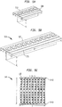
- Fig. 5A shows a perspective view 500 of a T-shaped integrated support heat sink 510 for a PCB 520 having an array of LEDs such as PCB 220A according to the present invention.
- the T-shaped integrated support heat sink 510 has a width, w, of approximately 1.5 inches and a height, h, of approximately 1 inch.
- the length, 1, is approximately 5.5 inches. However, the length, 1, and number of LEDs affixed to a T-shaped heat sink varies depending on the particular type of lighting application.
- the T-shaped heat sink 510 is made from thermally conductive material and is preferably a T-shaped aluminum bar.
- PCB 520 is fixedly attached to the T-shaped heat sink 510.
- the T-shaped heat sink 510 provides heat dissipation of the array of LEDs mounted to PCB 520.
- Fig. 5B shows a perspective view of a T-shaped LED array module 530 in accordance with the present invention.
- T-shaped LED array module 530 include a T-shaped heat sink 525 and a PCB 535 containing ten LEDs fixedly mounted on the top surface of the T-shaped heat sink 525.
- the T-shaped heat sink 525 has a width of approximately 1 inch, a height of approximately 1 inch, and a length of approximately 12 inches.
- the T-shaped heat sink 525 is made from thermally conductive material such as aluminum, is approximately 1/16 inch thick, and is optionally painted anodized black.
- Fig. 5C shows a top view of a 1 foot x 1 foot LED lighting package 540 having nine LED lighting arrays such as T-shaped LED array module 530 for a total of 90 LEDs.
- LED lighting package 540 includes two L-shaped support bars 545A and 545B.
- the T-shaped LED arrays are attached to the inside surface the L-shaped support bars 545A and 545B and spaced at an equal distance, s, of approximately 1/4 inch. Since the LEDs are positioned so close to each other, color uniformity is achieved.
- Two L-shaped support bars 545A and 545B are optionally anodized in black to help the heat be drawn from the LEDs and are made with thermally conductive material such as aluminum.
- LED lighting package 540 allows 90 one watt LEDs to be placed in close proximity within a 1 foot x 1 foot area. LED lighting package 540 may be suitably utilized in a high intensity density (HID) lighting application such as a high bay warehouse lighting application. It is noted that although support bars 545A and 545B are shown as L-shaped, other shaped bars may be utilized such as T-shape and Z-shape support bars.
- HID high intensity density
- Fig. 6 shows a side view of a lighting package 600 employing the T-shaped heat sink 510 in accordance with the present invention.
- the lighting package 600 includes an L-shaped bar 620 having a width of approximately 1/8 inch, a vertical length of approximately 3 inches, and a horizontal length of approximately 2.5 inches.
- the L-shaped bar 620 is preferably constructed from thermally conductive material such as aluminum.
- the ends of the L-shaped bar are optionally flanged to support a piece of transparent synthetic resinous material 650 such as acrylic, Plexiglas®, and the like.
- the flanged ends are approximately .25 inches long.
- the T-shaped heat sink 510 is fixedly mounted to the inner surfaces of the L-shaped bar 620.
- the bottom outer surface of the L-shaped bar 620 is fixedly mounted to the outer surface of the top portion of a hinge 640.
- the outer surface of the bottom portion of the hinge 640 is fixedly mounted to plate 630.
- the hinge 640 allows the light emitted from the array of LEDs 520 to be adjusted and aligned with a subject.
- the optional piece of transparent synthetic resinous material 650 is mounted on the flanged ends of the L-shaped bar 620. It should be recognized that rather than the L-shaped bar 620, an equal side corner bar may be alternatively utilized.
- Figs. 7A-7D show lighting packages which dissipate heat from an array of LEDs mounted therein in accordance with the present invention.
- Fig. 7A shows a perspective view of a lighting package 700 in the shape of a trapezoidal channel 710.
- the trapezoidal channel 710 has a base 705 at the bottom of the channel and two sides 715A-715B extending at obtuse angles from the base 705.
- the trapezoidal channel 710 has a thickness of approximately 1/16 inch and is made from thermal conductive material such as aluminum.
- Base 705 is approximately 2 inches.
- the height of the top edge of sides 715A-715B as measured according to a normal line projected to a plane defined by base 705 is approximately 1 inch.
- the distance, t, between the top edges of sides 715A - 715B is approximately 3 inches.
- the length of the trapezoidal channel 710, 1, varies with the particular type of lighting application.
- the inside surface of the trapezoidal channel 710 is preferably anodized with a white gloss.
- a PCB 720 containing LEDS is fixedly mounted at the top of base 705.
- PCB 720 may suitably be similar to PCB 520.
- Trapezoidal channel 710 serves as a heat sink as well as a LED light package. Other channel shapes may be employed as an LED lighting package.
- Fig. 7B shows a side view of a lighting package 730 having a channel with constant curvature
- Fig. 7C shows a side view of a lighting package 740 in the shape of a rectangular channel
- Lighting package 740 has PCB 720 fixedly mounted to the base of the lighting package 740.
- Fig. 7D shows a side view of a lighting package 740 in the shape of a parabolic channel.
- Lighting packages 730 and 750 has PCB 720 mounted through a T-shaped heat sink such as heat sink 510.
- transparent synthetic resinous material such as acrylic, Plexiglas®, and the like may be affixed to the top of LED lighting packages 710, 730, 740, and 750.
- the spacing in the above packages balances color uniformity, heat dissipation, brightness, and cost for Cree's XLampTM 7090 for a particular lighting application and addresses other LEDs having similar operating characteristics of the XLampTM 7090.
- Fig. 8 shows a control system 800 for one or more LED lighting packages.
- lighting application 422 utilizes six LED lighting packages.
- control system 800 may be suitably employed to selectively apply power to one or more of six LED lighting packages and to simultaneously vary the brightness of one or more of the six LED lighting packages. During brightness adjustment, the activated LED lighting packages are adjusted together so as to output the same brightness level.
- Control system 800 includes six direct current (DC) power supplies 810A - 810F, a potentiometer 820, and an Ethernet control relay switch. Each power supply supplies power to a corresponding LED lighting package such as lighting packages 200, 240, 300, 400, and 410.
- DC direct current
- power supplies 810B - 810F may suitably be similar and employ similar or identical equipment.
- power supplies 810B - 810F may employ different equipment from that of the item 810A and of one another, so long as they are able to communicate with potentiometer 820.
- Power supplies 810A-810F may be suitably a constant current supply with appropriate wattage such as model PS1-150W-36, manufactured by PowerSupplyl. Power supplies 810A-810F have a positive DC output terminal electrically connected to Ethernet control relay switch 830 and a negative DC output terminal electrically connected to ground. Power supplies 810A-810F also have an analog control port such as analog control port 815 which is electrically connected to potentiometer 820.
- the potentiometer 820 preferably includes an Ethernet control port and is preferably connected to a wireless router 840. Potentiometer 820 is well known and may include generally available 1 kiloohm, 1 watt potentiometer having an integrated Ethernet.
- the Ethernet control relay switch 830 includes at least six output ports such as output port 825. Each output port is electrically connected to a corresponding LED lighting package.
- the Ethernet control relay switch 830 also includes an Ethernet control port 835 which is preferably connected to the wireless router 840.
- Ethernet control relay switch 830 may suitably be a Smart Relay Controller, manufactured by 6Bit Incorporated having six 10 amp relays.
- a laptop 850 with a wireless adapter wirelessly communicates with the wireless router 840 to control either the Ethernet control relay switch 830 to selectively power one or more LED lighting packages, the potentiometer 820 to vary together the brightness level of LED lighting packages, or both.
- Power supplies 810A-810F receive input from an alternating current (AC) power source (not shown).
- the AC power source may provide 120 volts (V) at 20 amps (A) or a range of 220 V-240V at 20A.
- the input AC power runs between 50 and 60 hertz (Hz).
- the output power of power supplies 810A-810F matches the DC operating conditions of at most six columns of 20 serially connected LEDs where each column is electrically connected in parallel.
- the designed operating range for an LED such as LED 10 is to receive constant current around 350 mA. Consequently, for each power supply to power an LED lighting package such lighting packages 400 and 410, each power supply outputs 36V at 4.2 Amps.
- the Ethernet control relay switch 830 is controlled by a laptop through its Ethernet port 835 to connect one or more power supplies 810A-810F to their corresponding LED lighting packages.
- the potentiometer is manually controlled or controlled by laptop 850 to, in turn, vary the output voltage of power supplies 810A-810F simultaneously to the connected LED lighting packages.
- the combination of relay control and brightness control of the LED lighting packages provides a two dimensional adjustment.
- Laptop 850 may alternatively employ music to control both the potentiometer 820 and Ethernet control relay switch 830 so that the LED lighting packages emit lighting patterns corresponding to the beat of the music.
- LED lighting packages have been disclosed in the context of an XLampTM 7090 from Cree, Incorporated, the dimensions disclosed within a package such as spacing between members may vary based on the operating characteristics of a particular LED such as the XLampTM 3 7090, XLampTM 4550, and the like when employed by the LED lighting packages.
- LED lighting packages 200, 240, 300, 400, 410, and 540 and T-shaped integrated support heat sink 510 are modular components and may be combined with themselves or with each other to make various arrangements and configurations of larger LED lighting packages to meet specific lighting applications. Additionally, LED lighting packages 200, 240, 300, 400, and 410 and their combinations may be mounted and/or retrofitted into existing non-LED lamp fixtures including fluorescent ceiling fixtures. In retrofitting existing LED lighting packages to existing fluorescent lamp fixtures according to the teachings of the present invention, alternating current (AC) to DC conversion circuitry may need to be added or replaced in a manner known to one having ordinary skill in the art. Alternatively, AC may be supplied to the LED lighting packages.
- AC alternating current
- various layers may proximately cover LED lighting packages and integrated support heat sinks disclosed herein including diffusers, collimators, optics, lens, and the like.
- a diffuser is generally placed approximately 4 inches from the LEDs in the LED lighting packages to blend the light emitted.
- the spacing may be selected to achieve a desired color uniformity or appearance.
- An LED module which includes PCB and LED combination mounted on a thermally conductive backing such as LED module 317 is modular and may be arranged to address various configurations according to a specific lighting application.
- Fig. 9 illustrates various exemplary arrangements 900 of LED modules to define alternative LED lighting packages in accordance with the present invention.
- the LED lighting packages may include LED modules and/or support members without LEDs.
- the LED modules or support members have been described as strips, alternative shapes and/or lengths for the LED modules may be utilized.
- the printed circuit boards (PCBs) containing one or more LEDs described in the above embodiments is preferably mounted to thermally conductive material utilizing a thermal apoxy such as such as Loctite® 384, other well known techniques including utilizing screws, rivets, and the like are also contemplated by the present invention.
- the PCBs described above may be painted white to help reflect emitted light or black to help heat dissipation depending on the particular lighting application.
Landscapes
- Engineering & Computer Science (AREA)
- General Engineering & Computer Science (AREA)
- Physics & Mathematics (AREA)
- Microelectronics & Electronic Packaging (AREA)
- Optics & Photonics (AREA)
- Arrangement Of Elements, Cooling, Sealing, Or The Like Of Lighting Devices (AREA)
- Non-Portable Lighting Devices Or Systems Thereof (AREA)
- Fastening Of Light Sources Or Lamp Holders (AREA)
Applications Claiming Priority (2)
| Application Number | Priority Date | Filing Date | Title |
|---|---|---|---|
| US11/379,709 US7648257B2 (en) | 2006-04-21 | 2006-04-21 | Light emitting diode packages |
| PCT/US2007/066417 WO2007124276A2 (en) | 2006-04-21 | 2007-04-11 | Light emitting diode packages |
Publications (3)
| Publication Number | Publication Date |
|---|---|
| EP2010819A2 EP2010819A2 (en) | 2009-01-07 |
| EP2010819A4 EP2010819A4 (en) | 2013-09-11 |
| EP2010819B1 true EP2010819B1 (en) | 2018-03-07 |
Family
ID=38619304
Family Applications (1)
| Application Number | Title | Priority Date | Filing Date |
|---|---|---|---|
| EP07760470.0A Active EP2010819B1 (en) | 2006-04-21 | 2007-04-11 | Light emitting diode packages |
Country Status (4)
| Country | Link |
|---|---|
| US (2) | US7648257B2 (https=) |
| EP (1) | EP2010819B1 (https=) |
| JP (1) | JP2009534851A (https=) |
| WO (1) | WO2007124276A2 (https=) |
Families Citing this family (134)
| Publication number | Priority date | Publication date | Assignee | Title |
|---|---|---|---|---|
| US7564180B2 (en) | 2005-01-10 | 2009-07-21 | Cree, Inc. | Light emission device and method utilizing multiple emitters and multiple phosphors |
| US8125137B2 (en) | 2005-01-10 | 2012-02-28 | Cree, Inc. | Multi-chip light emitting device lamps for providing high-CRI warm white light and light fixtures including the same |
| EP1963743B1 (en) | 2005-12-21 | 2016-09-07 | Cree, Inc. | Lighting device |
| EP2372223A3 (en) | 2005-12-21 | 2012-08-01 | Cree, Inc. | Lighting Device and Lighting Method |
| EP1969633B1 (en) | 2005-12-22 | 2018-08-29 | Cree, Inc. | Lighting device |
| US9084328B2 (en) | 2006-12-01 | 2015-07-14 | Cree, Inc. | Lighting device and lighting method |
| US8513875B2 (en) | 2006-04-18 | 2013-08-20 | Cree, Inc. | Lighting device and lighting method |
| EP2052589A4 (en) | 2006-04-18 | 2012-09-19 | Cree Inc | LIGHTING DEVICE AND METHOD |
| KR101517244B1 (ko) | 2006-04-20 | 2015-05-04 | 크리, 인코포레이티드 | 조명 기기 및 조명 방법 |
| US7648257B2 (en) * | 2006-04-21 | 2010-01-19 | Cree, Inc. | Light emitting diode packages |
| US8596819B2 (en) | 2006-05-31 | 2013-12-03 | Cree, Inc. | Lighting device and method of lighting |
| JP4729441B2 (ja) * | 2006-06-09 | 2011-07-20 | スタンレー電気株式会社 | 車両用灯具 |
| JP2010500720A (ja) * | 2006-08-11 | 2010-01-07 | エルジー イノテック カンパニー リミテッド | ライトユニット及びこれを備えた液晶表示装置 |
| US7665862B2 (en) * | 2006-09-12 | 2010-02-23 | Cree, Inc. | LED lighting fixture |
| US7766508B2 (en) * | 2006-09-12 | 2010-08-03 | Cree, Inc. | LED lighting fixture |
| JP4981390B2 (ja) * | 2006-09-20 | 2012-07-18 | オスラム・メルコ株式会社 | Ledランプ |
| US9564070B2 (en) | 2006-10-05 | 2017-02-07 | GE Lighting Solutions, LLC | LED backlighting system for cabinet sign |
| US8029155B2 (en) | 2006-11-07 | 2011-10-04 | Cree, Inc. | Lighting device and lighting method |
| JP5324458B2 (ja) * | 2006-11-14 | 2013-10-23 | クリー インコーポレイテッド | 照明アセンブリー、および照明アセンブリーのための構成要素 |
| EP2095014B1 (en) | 2006-11-14 | 2017-05-10 | Cree, Inc. | Light engine assemblies |
| US9441793B2 (en) | 2006-12-01 | 2016-09-13 | Cree, Inc. | High efficiency lighting device including one or more solid state light emitters, and method of lighting |
| EP2089654B1 (en) | 2006-12-07 | 2016-08-03 | Cree, Inc. | Lighting device and lighting method |
| US8258682B2 (en) * | 2007-02-12 | 2012-09-04 | Cree, Inc. | High thermal conductivity packaging for solid state light emitting apparatus and associated assembling methods |
| US7922360B2 (en) * | 2007-02-14 | 2011-04-12 | Cree, Inc. | Thermal transfer in solid state light emitting apparatus and methods of manufacturing |
| KR101499269B1 (ko) | 2007-02-22 | 2015-03-09 | 크리, 인코포레이티드 | 발광 장치, 발광 방법, 광 필터 및 광 필터링 방법 |
| US7824070B2 (en) | 2007-03-22 | 2010-11-02 | Cree, Inc. | LED lighting fixture |
| US7690802B2 (en) * | 2007-04-17 | 2010-04-06 | Cree, Inc. | Light emitting diode emergency lighting methods and apparatus |
| ES1065356Y (es) * | 2007-04-24 | 2007-11-01 | Luxintec S L | Regleta para iluminacion con fuentes de luz led |
| US7901107B2 (en) | 2007-05-08 | 2011-03-08 | Cree, Inc. | Lighting device and lighting method |
| KR20100020464A (ko) | 2007-05-08 | 2010-02-22 | 크리 엘이디 라이팅 솔루션즈, 인크. | 조명 장치 및 조명 방법 |
| WO2008137975A1 (en) | 2007-05-08 | 2008-11-13 | Cree Led Lighting Solutions, Inc. | Lighting device and lighting method |
| KR101460832B1 (ko) | 2007-05-08 | 2014-11-12 | 크리, 인코포레이티드 | 조명 장치 및 조명 방법 |
| TWI422785B (zh) | 2007-05-08 | 2014-01-11 | 克里公司 | 照明裝置及照明方法 |
| US8042971B2 (en) | 2007-06-27 | 2011-10-25 | Cree, Inc. | Light emitting device (LED) lighting systems for emitting light in multiple directions and related methods |
| US20090002979A1 (en) * | 2007-06-27 | 2009-01-01 | Cree, Inc. | Light emitting device (led) lighting systems for emitting light in multiple directions and related methods |
| US7863635B2 (en) | 2007-08-07 | 2011-01-04 | Cree, Inc. | Semiconductor light emitting devices with applied wavelength conversion materials |
| US8143777B2 (en) * | 2007-08-23 | 2012-03-27 | Stanley Electric Co., Ltd. | LED lighting unit with LEDs and phosphor materials |
| KR101722265B1 (ko) | 2007-10-10 | 2017-03-31 | 크리, 인코포레이티드 | 조명 장치 및 그 제조 방법 |
| US8118447B2 (en) | 2007-12-20 | 2012-02-21 | Altair Engineering, Inc. | LED lighting apparatus with swivel connection |
| US7712918B2 (en) | 2007-12-21 | 2010-05-11 | Altair Engineering , Inc. | Light distribution using a light emitting diode assembly |
| US8322881B1 (en) | 2007-12-21 | 2012-12-04 | Appalachian Lighting Systems, Inc. | Lighting fixture |
| US8360599B2 (en) | 2008-05-23 | 2013-01-29 | Ilumisys, Inc. | Electric shock resistant L.E.D. based light |
| WO2009148449A1 (en) * | 2008-06-05 | 2009-12-10 | Relume Corporation | Light engine with enhanced heat transfer using independent elongated strips |
| US8240875B2 (en) | 2008-06-25 | 2012-08-14 | Cree, Inc. | Solid state linear array modules for general illumination |
| US7976196B2 (en) | 2008-07-09 | 2011-07-12 | Altair Engineering, Inc. | Method of forming LED-based light and resulting LED-based light |
| US7946729B2 (en) | 2008-07-31 | 2011-05-24 | Altair Engineering, Inc. | Fluorescent tube replacement having longitudinally oriented LEDs |
| US8674626B2 (en) | 2008-09-02 | 2014-03-18 | Ilumisys, Inc. | LED lamp failure alerting system |
| US8256924B2 (en) | 2008-09-15 | 2012-09-04 | Ilumisys, Inc. | LED-based light having rapidly oscillating LEDs |
| US8444292B2 (en) | 2008-10-24 | 2013-05-21 | Ilumisys, Inc. | End cap substitute for LED-based tube replacement light |
| US8901823B2 (en) | 2008-10-24 | 2014-12-02 | Ilumisys, Inc. | Light and light sensor |
| US7938562B2 (en) | 2008-10-24 | 2011-05-10 | Altair Engineering, Inc. | Lighting including integral communication apparatus |
| US8214084B2 (en) | 2008-10-24 | 2012-07-03 | Ilumisys, Inc. | Integration of LED lighting with building controls |
| US8324817B2 (en) | 2008-10-24 | 2012-12-04 | Ilumisys, Inc. | Light and light sensor |
| US8653984B2 (en) | 2008-10-24 | 2014-02-18 | Ilumisys, Inc. | Integration of LED lighting control with emergency notification systems |
| KR101308752B1 (ko) * | 2008-12-31 | 2013-09-12 | 엘지디스플레이 주식회사 | 액정표시장치 |
| US8556452B2 (en) | 2009-01-15 | 2013-10-15 | Ilumisys, Inc. | LED lens |
| US8362710B2 (en) | 2009-01-21 | 2013-01-29 | Ilumisys, Inc. | Direct AC-to-DC converter for passive component minimization and universal operation of LED arrays |
| US8664880B2 (en) | 2009-01-21 | 2014-03-04 | Ilumisys, Inc. | Ballast/line detection circuit for fluorescent replacement lamps |
| KR20100092696A (ko) * | 2009-02-13 | 2010-08-23 | 엘지이노텍 주식회사 | 발광 모듈 및 이를 구비한 라이트 유닛 |
| US8330381B2 (en) | 2009-05-14 | 2012-12-11 | Ilumisys, Inc. | Electronic circuit for DC conversion of fluorescent lighting ballast |
| US8299695B2 (en) | 2009-06-02 | 2012-10-30 | Ilumisys, Inc. | Screw-in LED bulb comprising a base having outwardly projecting nodes |
| US8921876B2 (en) | 2009-06-02 | 2014-12-30 | Cree, Inc. | Lighting devices with discrete lumiphor-bearing regions within or on a surface of remote elements |
| KR101660721B1 (ko) * | 2009-06-15 | 2016-09-29 | 엘지전자 주식회사 | 발광 다이오드 패키지 및 이를 포함하는 백라이트 유닛과 디스플레이장치 |
| KR101628366B1 (ko) * | 2009-07-06 | 2016-06-08 | 엘지전자 주식회사 | 광학 어셈블리, 이를 구비한 백라이트 유닛 및 디스플레이 장치 |
| CA2765200A1 (en) | 2009-06-23 | 2011-01-13 | Altair Engineering, Inc. | Illumination device including leds and a switching power control system |
| CN102472449B (zh) * | 2009-07-31 | 2013-12-04 | 夏普株式会社 | 背光源装置、显示装置以及电视接收机 |
| WO2011037877A1 (en) | 2009-09-25 | 2011-03-31 | Cree, Inc. | Lighting device with low glare and high light level uniformity |
| US20110080108A1 (en) * | 2009-10-06 | 2011-04-07 | Walsin Lihwa Corporation | Color tunable light emitting diode |
| JP5340879B2 (ja) * | 2009-10-13 | 2013-11-13 | スタンレー電気株式会社 | 発光装置 |
| EP2354817A1 (en) * | 2009-12-14 | 2011-08-10 | Lg Electronics Inc. | Backlight unit, and display apparatus including the backlight unit |
| US9275979B2 (en) | 2010-03-03 | 2016-03-01 | Cree, Inc. | Enhanced color rendering index emitter through phosphor separation |
| JP5571419B2 (ja) * | 2010-03-24 | 2014-08-13 | スタンレー電気株式会社 | 車両用前照灯 |
| US8541958B2 (en) | 2010-03-26 | 2013-09-24 | Ilumisys, Inc. | LED light with thermoelectric generator |
| CA2794512A1 (en) | 2010-03-26 | 2011-09-29 | Ilumisys, Inc. | Led light tube with dual sided light distribution |
| WO2011119958A1 (en) | 2010-03-26 | 2011-09-29 | Altair Engineering, Inc. | Inside-out led bulb |
| US20110254470A1 (en) * | 2010-04-19 | 2011-10-20 | Gregory James Penoyer | Collapsible Lighting Device |
| US8454193B2 (en) | 2010-07-08 | 2013-06-04 | Ilumisys, Inc. | Independent modules for LED fluorescent light tube replacement |
| US8596813B2 (en) | 2010-07-12 | 2013-12-03 | Ilumisys, Inc. | Circuit board mount for LED light tube |
| US8414153B2 (en) | 2010-08-05 | 2013-04-09 | Access 2 Communications, Inc. | High powered universal LED lamp |
| US20120036748A1 (en) * | 2010-08-13 | 2012-02-16 | Yu-Chung Yen | DIY LED sign panel arrangement |
| FR2964176B1 (fr) * | 2010-09-01 | 2015-10-16 | Saint Gobain | Panneau decoratif et eclairant a diodes electroluminescentes |
| KR101220834B1 (ko) * | 2011-02-16 | 2013-01-21 | (주)라이트스탠다드 | 방열성능의 향상 및 전압강하의 방지를 위한 고광력 엘이디 광원 구조체 |
| US8035284B2 (en) * | 2010-09-22 | 2011-10-11 | Bridgelux, Inc. | Distributed LED-based light source |
| JP2012069834A (ja) * | 2010-09-27 | 2012-04-05 | Toshiba Lighting & Technology Corp | 発光装置及び照明装置 |
| EP2633227B1 (en) | 2010-10-29 | 2018-08-29 | iLumisys, Inc. | Mechanisms for reducing risk of shock during installation of light tube |
| US8870415B2 (en) | 2010-12-09 | 2014-10-28 | Ilumisys, Inc. | LED fluorescent tube replacement light with reduced shock hazard |
| US11251164B2 (en) | 2011-02-16 | 2022-02-15 | Creeled, Inc. | Multi-layer conversion material for down conversion in solid state lighting |
| US9072171B2 (en) | 2011-08-24 | 2015-06-30 | Ilumisys, Inc. | Circuit board mount for LED light |
| EP2745289A1 (en) | 2011-09-06 | 2014-06-25 | Koninklijke Philips N.V. | Topology of distributing and connecting leds in a large area matrix |
| US8307547B1 (en) | 2012-01-16 | 2012-11-13 | Indak Manufacturing Corp. | Method of manufacturing a circuit board with light emitting diodes |
| US8733969B2 (en) | 2012-01-22 | 2014-05-27 | Ecolivegreen Corp. | Gradient diffusion globe LED light and fixture for the same |
| WO2013131002A1 (en) | 2012-03-02 | 2013-09-06 | Ilumisys, Inc. | Electrical connector header for an led-based light |
| US8888313B2 (en) | 2012-03-07 | 2014-11-18 | Harris Manufacturing, Inc. | Light emitting diode troffer door assembly |
| US10347609B2 (en) * | 2012-05-04 | 2019-07-09 | Micron Technology, Inc. | Solid-state transducer assemblies with remote converter material for improved light extraction efficiency and associated systems and methods |
| USD701342S1 (en) | 2012-05-25 | 2014-03-18 | Joshua David Company | Light fixture assembly |
| WO2014008463A1 (en) | 2012-07-06 | 2014-01-09 | Ilumisys, Inc. | Power supply assembly for led-based light tube |
| US9271367B2 (en) | 2012-07-09 | 2016-02-23 | Ilumisys, Inc. | System and method for controlling operation of an LED-based light |
| US8974077B2 (en) | 2012-07-30 | 2015-03-10 | Ultravision Technologies, Llc | Heat sink for LED light source |
| JP6024957B2 (ja) * | 2012-09-24 | 2016-11-16 | 東芝ライテック株式会社 | 発光装置および照明装置 |
| US9285084B2 (en) | 2013-03-14 | 2016-03-15 | Ilumisys, Inc. | Diffusers for LED-based lights |
| US20140286005A1 (en) * | 2013-03-20 | 2014-09-25 | Independence Led Lighting, Llc | Lighting Device Having Optimized Placement of Light-Emitting Elements for Parabolic Fixtures |
| CN104241262B (zh) | 2013-06-14 | 2020-11-06 | 惠州科锐半导体照明有限公司 | 发光装置以及显示装置 |
| CN103322534A (zh) * | 2013-06-21 | 2013-09-25 | 深圳市华星光电技术有限公司 | 直下型背光模组灯条装配结构、组装方法及液晶显示器 |
| SG11201602319TA (en) * | 2013-08-26 | 2016-05-30 | Delta T Corp | Tunable luminaire and related methods to control light output |
| US9267650B2 (en) | 2013-10-09 | 2016-02-23 | Ilumisys, Inc. | Lens for an LED-based light |
| WO2015084851A1 (en) | 2013-12-04 | 2015-06-11 | 3M Innovative Properties Company | Flexible light emitting semiconductor device with large area conduit |
| EP3097748A1 (en) | 2014-01-22 | 2016-11-30 | iLumisys, Inc. | Led-based light with addressed leds |
| US9903540B2 (en) * | 2014-02-06 | 2018-02-27 | Appalachian Lighting Systems, Inc. | LED light emitting apparatus having both reflected and diffused subassemblies |
| US9510400B2 (en) | 2014-05-13 | 2016-11-29 | Ilumisys, Inc. | User input systems for an LED-based light |
| US12372219B2 (en) * | 2014-05-30 | 2025-07-29 | Cree Lighting Usa Llc | LED luminaire with a cavity, finned interior, and a curved outer wall extending from a surface on which the light source is mounted |
| US20170138562A1 (en) * | 2014-06-12 | 2017-05-18 | Westland Joaus Technologies, Llc | System, devices, and methods for illumination including solid-state light emitting devices |
| EP3174612B1 (en) | 2014-08-01 | 2019-09-04 | Smart Billiard Lighting LLC | Billiard table lighting and game play monitor |
| US9827483B2 (en) | 2014-08-01 | 2017-11-28 | Smart Billiard Lighting LLC | Billiard table lighting and game play monitor |
| US10149439B2 (en) | 2014-12-18 | 2018-12-11 | Spectra Harvest Lighting, LLC | LED grow light system |
| US10161568B2 (en) | 2015-06-01 | 2018-12-25 | Ilumisys, Inc. | LED-based light with canted outer walls |
| USD835652S1 (en) | 2015-12-10 | 2018-12-11 | Smart Billiard Lighting LLC | Display screen with transitional graphical user interface of a billiard game |
| DE102016203883A1 (de) * | 2016-03-09 | 2017-09-14 | Osram Gmbh | Leuchtdiodenanordnung für eine Flächenleuchte |
| WO2017210361A1 (en) * | 2016-05-31 | 2017-12-07 | Air Motion Systems, Inc. | Air cooled array and system for cooling light emitting diode systems |
| USD822890S1 (en) | 2016-09-07 | 2018-07-10 | Felxtronics Ap, Llc | Lighting apparatus |
| CN106444158A (zh) * | 2016-12-07 | 2017-02-22 | 超亮显示系统(深圳)股份有限公司 | 一种大尺寸液晶屏led矩阵直下式高亮背光模组 |
| CN107068006A (zh) | 2017-03-22 | 2017-08-18 | 四川蓝景光电技术有限责任公司 | Led灯箱及显示装置 |
| US10775030B2 (en) | 2017-05-05 | 2020-09-15 | Flex Ltd. | Light fixture device including rotatable light modules |
| USD846793S1 (en) | 2017-08-09 | 2019-04-23 | Flex Ltd. | Lighting module locking mechanism |
| USD832494S1 (en) | 2017-08-09 | 2018-10-30 | Flex Ltd. | Lighting module heatsink |
| USD833061S1 (en) | 2017-08-09 | 2018-11-06 | Flex Ltd. | Lighting module locking endcap |
| USD877964S1 (en) | 2017-08-09 | 2020-03-10 | Flex Ltd. | Lighting module |
| USD872319S1 (en) | 2017-08-09 | 2020-01-07 | Flex Ltd. | Lighting module LED light board |
| USD862777S1 (en) | 2017-08-09 | 2019-10-08 | Flex Ltd. | Lighting module wide distribution lens |
| USD832495S1 (en) | 2017-08-18 | 2018-10-30 | Flex Ltd. | Lighting module locking mechanism |
| USD862778S1 (en) | 2017-08-22 | 2019-10-08 | Flex Ltd | Lighting module lens |
| USD888323S1 (en) | 2017-09-07 | 2020-06-23 | Flex Ltd | Lighting module wire guard |
| USD856569S1 (en) * | 2017-11-09 | 2019-08-13 | Illum Horticulture Llc | Light fixture |
| WO2021209492A1 (en) * | 2020-04-15 | 2021-10-21 | CommScope Connectivity Belgium BV | Device and method for sealing cables in telecommunications enclosures |
| US12338960B1 (en) * | 2025-02-24 | 2025-06-24 | Jiawei WANG | IC control light bulb, LED light strip and IC controller |
Family Cites Families (119)
| Publication number | Priority date | Publication date | Assignee | Title |
|---|---|---|---|---|
| US1565500A (en) | 1924-12-03 | 1925-12-15 | Ritter Edward | Electric vaporizer |
| US1775619A (en) * | 1927-10-07 | 1930-09-09 | Redirected Light Corp Of Ameri | Headlight |
| GB1494493A (en) | 1974-03-05 | 1977-12-07 | Thorn Electrical Ind Ltd | Lamp-holder with heat-sink |
| US3927290A (en) | 1974-11-14 | 1975-12-16 | Teletype Corp | Selectively illuminated pushbutton switch |
| US4163277A (en) | 1977-08-12 | 1979-07-31 | Altman Charles W | Spotlight |
| US4165851A (en) | 1977-09-28 | 1979-08-28 | Slater Electric Inc. | Adjustably lockable bar hanger for ceiling boxes and the like |
| US4219871A (en) | 1978-05-22 | 1980-08-26 | The United States Of America As Represented By The Secretary Of The Navy | High intensity navigation light |
| US4388677A (en) | 1981-01-02 | 1983-06-14 | Prescolite, A Div. Of U.S. Industries | Recessed lighting unit |
| JPS58144885U (ja) * | 1982-03-26 | 1983-09-29 | 株式会社日立製作所 | 発光体の固定装置 |
| US4480291A (en) * | 1983-09-14 | 1984-10-30 | Dranginis William M | Headlights for streamlined vehicles |
| AT396675B (de) * | 1985-12-04 | 1993-11-25 | Zizala Lichtsysteme Gmbh | Fahrzeugleuchte |
| CA2005294C (en) | 1988-12-14 | 1994-11-15 | Raymond S. Laughlin | Box support |
| US5264997A (en) | 1992-03-04 | 1993-11-23 | Dominion Automotive Industries Corp. | Sealed, inductively powered lamp assembly |
| KR970006293B1 (ko) | 1992-10-06 | 1997-04-25 | 캐논 가부시끼가이샤 | 원고 조명 장치 |
| US5632551A (en) | 1994-07-18 | 1997-05-27 | Grote Industries, Inc. | LED vehicle lamp assembly |
| US5537301A (en) | 1994-09-01 | 1996-07-16 | Pacific Scientific Company | Fluorescent lamp heat-dissipating apparatus |
| JPH08116096A (ja) * | 1994-10-14 | 1996-05-07 | Hamamatsu Photonics Kk | 発光装置 |
| US5588737A (en) | 1994-11-10 | 1996-12-31 | Thomas Industries, Inc. | Modular recessed lighting system |
| DE19528459C2 (de) | 1995-08-03 | 2001-08-23 | Garufo Gmbh | Kühlung für ein mit LED's bestücktes Leuchtaggregat |
| US5834889A (en) | 1995-09-22 | 1998-11-10 | Gl Displays, Inc. | Cold cathode fluorescent display |
| CA2161051A1 (en) | 1995-10-20 | 1997-04-21 | Howard Sirkin | Pot light mounting clip |
| US6076936A (en) | 1996-11-25 | 2000-06-20 | George; Ben | Tread area and step edge lighting system |
| US5934788A (en) | 1997-03-10 | 1999-08-10 | Prescolite-Moldcast Lighting Company | Recessed lighting trim structure |
| US6441943B1 (en) | 1997-04-02 | 2002-08-27 | Gentex Corporation | Indicators and illuminators using a semiconductor radiation emitter package |
| US5850126A (en) | 1997-04-11 | 1998-12-15 | Kanbar; Maurice S. | Screw-in led lamp |
| US6211626B1 (en) | 1997-08-26 | 2001-04-03 | Color Kinetics, Incorporated | Illumination components |
| US7014336B1 (en) | 1999-11-18 | 2006-03-21 | Color Kinetics Incorporated | Systems and methods for generating and modulating illumination conditions |
| US6292901B1 (en) | 1997-08-26 | 2001-09-18 | Color Kinetics Incorporated | Power/data protocol |
| GB2329238A (en) | 1997-09-12 | 1999-03-17 | Hassan Paddy Abdel Salam | LED light source |
| US6186650B1 (en) * | 1997-12-09 | 2001-02-13 | Cooper Automotive Products, Inc. | Vehicle headlamp with beamforming waveguide |
| JPH11208020A (ja) * | 1998-01-23 | 1999-08-03 | Canon Inc | 露光装置 |
| US6076788A (en) | 1998-06-22 | 2000-06-20 | Cooper Industries | Reinforced hanger bar |
| US6278607B1 (en) | 1998-08-06 | 2001-08-21 | Dell Usa, L.P. | Smart bi-metallic heat spreader |
| USD417305S (en) | 1998-09-24 | 1999-11-30 | Prescolite-Moldcast Lighting Company | Recessed lighting fixture trim |
| USD417307S (en) | 1998-09-24 | 1999-11-30 | Prescolite-Moldcast Lighting Company | Recessed lighting fixture trim |
| USD417306S (en) | 1998-09-24 | 1999-11-30 | Prescolite-Moldcast Lighting Company | Recessed lighting fixture trim |
| USD417747S (en) | 1998-10-14 | 1999-12-14 | Prescolite-Moldcast Lighting Company | Recessed lighting fixture trim |
| USD417746S (en) | 1998-10-14 | 1999-12-14 | Prescolite-Moldcast Lighting Company | Recessed lighting fixture trim |
| EP1006311A3 (de) | 1998-12-02 | 2001-10-04 | ERCO Leuchten GmbH | Leuchte nach Art einer Signal- und/oder Orientierungsleuchte |
| US6095671A (en) | 1999-01-07 | 2000-08-01 | Hutain; Barry | Actively cooled lighting trim apparatus |
| USD443949S1 (en) | 1999-05-26 | 2001-06-19 | Focal Point, Llc | Lighting fixture die-cast corner |
| USD428516S (en) | 1999-05-26 | 2000-07-18 | Focal Point, Llc | Lighting fixture quadra-partite dome reflector |
| USD430339S (en) | 1999-05-26 | 2000-08-29 | Focal Point Llc | Lighting fixture perforated lamp shield |
| USD437446S1 (en) | 1999-05-26 | 2001-02-06 | Focal Point, Llc | Lighting fixture |
| US6256200B1 (en) | 1999-05-27 | 2001-07-03 | Allen K. Lam | Symmetrical package for semiconductor die |
| US6335538B1 (en) | 1999-07-23 | 2002-01-01 | Impulse Dynamics N.V. | Electro-optically driven solid state relay system |
| US6504301B1 (en) | 1999-09-03 | 2003-01-07 | Lumileds Lighting, U.S., Llc | Non-incandescent lightbulb package using light emitting diodes |
| US6712486B1 (en) | 1999-10-19 | 2004-03-30 | Permlight Products, Inc. | Mounting arrangement for light emitting diodes |
| US6357889B1 (en) | 1999-12-01 | 2002-03-19 | General Electric Company | Color tunable light source |
| US6566808B1 (en) | 1999-12-22 | 2003-05-20 | General Electric Company | Luminescent display and method of making |
| US6482520B1 (en) | 2000-02-25 | 2002-11-19 | Jing Wen Tzeng | Thermal management system |
| US6517218B2 (en) | 2000-03-31 | 2003-02-11 | Relume Corporation | LED integrated heat sink |
| US6428189B1 (en) | 2000-03-31 | 2002-08-06 | Relume Corporation | L.E.D. thermal management |
| US6350043B1 (en) | 2000-07-21 | 2002-02-26 | Aerospace Lighting Corporation | Behind panel mount, directional lighting bracket |
| US6547416B2 (en) * | 2000-12-21 | 2003-04-15 | Koninklijke Philips Electronics N.V. | Faceted multi-chip package to provide a beam of uniform white light from multiple monochrome LEDs |
| US6624350B2 (en) | 2001-01-18 | 2003-09-23 | Arise Technologies Corporation | Solar power management system |
| US6684573B2 (en) * | 2001-05-04 | 2004-02-03 | Thyssen Elevator Capital Corp. | Elevator door sill assembly |
| US6578986B2 (en) | 2001-06-29 | 2003-06-17 | Permlight Products, Inc. | Modular mounting arrangement and method for light emitting diodes |
| US6889943B2 (en) | 2001-07-06 | 2005-05-10 | Thomas & Betts International, Inc. | Hanger bar assembly |
| CN1464953A (zh) * | 2001-08-09 | 2003-12-31 | 松下电器产业株式会社 | Led照明装置和卡型led照明光源 |
| JP2003059313A (ja) * | 2001-08-15 | 2003-02-28 | Koito Mfg Co Ltd | 車両用灯具 |
| DE60223050T2 (de) | 2001-08-31 | 2008-07-17 | Gentex Corp., Zeeland | Fahrzeuglampenanordnung mit kühlkörper |
| JP4013507B2 (ja) * | 2001-09-17 | 2007-11-28 | シーシーエス株式会社 | 発光パネル装置 |
| US6851834B2 (en) | 2001-12-21 | 2005-02-08 | Joseph A. Leysath | Light emitting diode lamp having parabolic reflector and diffuser |
| US7093958B2 (en) | 2002-04-09 | 2006-08-22 | Osram Sylvania Inc. | LED light source assembly |
| US6874911B2 (en) | 2002-04-09 | 2005-04-05 | Ccs, Inc. | Light irradiating unit, lighting unit and method for manufacturing lighting unit |
| JP4080780B2 (ja) * | 2002-04-23 | 2008-04-23 | 株式会社小糸製作所 | 光源ユニット |
| JP4068387B2 (ja) * | 2002-04-23 | 2008-03-26 | 株式会社小糸製作所 | 光源ユニット |
| JP4360481B2 (ja) * | 2002-07-10 | 2009-11-11 | 株式会社小糸製作所 | 車両用灯具 |
| JP4002159B2 (ja) * | 2002-09-03 | 2007-10-31 | 株式会社小糸製作所 | 車両用前照灯 |
| JP4083516B2 (ja) * | 2002-09-03 | 2008-04-30 | 株式会社小糸製作所 | 車両用前照灯 |
| JP4024628B2 (ja) * | 2002-09-03 | 2007-12-19 | 株式会社小糸製作所 | 車両用前照灯 |
| US6787999B2 (en) | 2002-10-03 | 2004-09-07 | Gelcore, Llc | LED-based modular lamp |
| AU2003296485A1 (en) * | 2002-12-11 | 2004-06-30 | Charles Bolta | Light emitting diode (l.e.d.) lighting fixtures with emergency back-up and scotopic enhancement |
| JP4047185B2 (ja) * | 2003-02-06 | 2008-02-13 | 株式会社小糸製作所 | 車両用前照灯及び発光モジュール |
| US7344296B2 (en) | 2003-02-07 | 2008-03-18 | Matsushita Electric Industrial Co., Ltd. | Socket for led light source and lighting system using the socket |
| JP4083593B2 (ja) * | 2003-02-13 | 2008-04-30 | 株式会社小糸製作所 | 車両用前照灯 |
| JP4037289B2 (ja) * | 2003-03-06 | 2008-01-23 | 株式会社小糸製作所 | 車両用前照灯 |
| JP4102240B2 (ja) * | 2003-04-08 | 2008-06-18 | 株式会社小糸製作所 | 車両用前照灯 |
| US6964507B2 (en) | 2003-04-25 | 2005-11-15 | Everbrite, Llc | Sign illumination system |
| EP1620676A4 (en) | 2003-05-05 | 2011-03-23 | Philips Solid State Lighting | LIGHTING PROCESSES AND SYSTEMS |
| US6864573B2 (en) | 2003-05-06 | 2005-03-08 | Daimlerchrysler Corporation | Two piece heat sink and device package |
| US6999318B2 (en) * | 2003-07-28 | 2006-02-14 | Honeywell International Inc. | Heatsinking electronic devices |
| DE10341219A1 (de) | 2003-09-04 | 2005-03-31 | Erco Leuchten Gmbh | Leuchte zur Anbringung an einer Gebäudefläche oder Gebäudeteilfläche |
| US7329024B2 (en) | 2003-09-22 | 2008-02-12 | Permlight Products, Inc. | Lighting apparatus |
| JP2005134858A (ja) * | 2003-10-07 | 2005-05-26 | Seiko Epson Corp | 光学装置及びリアプロジェクタ |
| DE20315543U1 (de) | 2003-10-09 | 2004-02-12 | Peters Design Gmbh | LED Einbauleuchtenprofil |
| US7102172B2 (en) | 2003-10-09 | 2006-09-05 | Permlight Products, Inc. | LED luminaire |
| JP2005159262A (ja) * | 2003-10-30 | 2005-06-16 | Kyocera Corp | 発光素子収納用パッケージおよび発光装置ならびに照明装置 |
| JP2005144679A (ja) | 2003-11-11 | 2005-06-09 | Roland Dg Corp | インクジェットプリンタ |
| US7144135B2 (en) | 2003-11-26 | 2006-12-05 | Philips Lumileds Lighting Company, Llc | LED lamp heat sink |
| US7329887B2 (en) | 2003-12-02 | 2008-02-12 | 3M Innovative Properties Company | Solid state light device |
| DE102004001940B4 (de) | 2004-01-14 | 2006-12-07 | Centrotherm Systemtechnik Gmbh | Leuchtbaustein und Verfahren zu seiner Herstellung |
| US20050168986A1 (en) | 2004-01-30 | 2005-08-04 | Scott Wegner | Reflector assemblies for luminaires |
| JP4339143B2 (ja) * | 2004-02-10 | 2009-10-07 | 株式会社小糸製作所 | 車両用灯具ユニット |
| CA2499137C (en) * | 2004-03-01 | 2012-07-17 | Lee W. Rempel | Box light |
| DE202004003793U1 (de) | 2004-03-11 | 2004-05-13 | Hella Kg Hueck & Co. | Leuchtdiodenanordnung, insbesondere zum Einbau in Fahrzeuge |
| US20050247842A1 (en) | 2004-05-10 | 2005-11-10 | Grzegorz Wronski | Hanger bar assemblies for recessed luminaires |
| DE102004019137A1 (de) | 2004-04-16 | 2005-11-17 | Trilux-Lenze Gmbh + Co Kg | Leuchtenfeld |
| US7210817B2 (en) | 2004-04-27 | 2007-05-01 | Avago Technologies Ecbu Ip (Singapore) Pte. Ltd. | Method, system and device for delivering phototherapy to a patient |
| US20050243556A1 (en) | 2004-04-30 | 2005-11-03 | Manuel Lynch | Lighting system and method |
| EP1600691A1 (en) | 2004-05-05 | 2005-11-30 | Lumodan ApS | Lamps and lamp assemblies |
| US8188503B2 (en) | 2004-05-10 | 2012-05-29 | Permlight Products, Inc. | Cuttable illuminated panel |
| KR100665298B1 (ko) | 2004-06-10 | 2007-01-04 | 서울반도체 주식회사 | 발광장치 |
| WO2006026575A2 (en) * | 2004-08-31 | 2006-03-09 | Herman Miller, Inc. | Visual shields with technology including led ladder, network connections and concertina effects |
| US7575354B2 (en) | 2004-09-16 | 2009-08-18 | Magna International Inc. | Thermal management system for solid state automotive lighting |
| KR101095637B1 (ko) | 2004-09-23 | 2011-12-19 | 삼성전자주식회사 | 광 발생 장치, 이를 갖는 백라이트 어셈블리 및 백라이트어셈블리를 갖는 표시장치 |
| ITFI20040269A1 (it) | 2004-12-23 | 2005-03-23 | Belisario Pini | Supporto contenitore orientabile |
| TWI262342B (en) * | 2005-02-18 | 2006-09-21 | Au Optronics Corp | Device for fastening lighting unit in backlight module |
| CN100468795C (zh) | 2005-06-03 | 2009-03-11 | 新灯源科技有限公司 | 整合导热/散热模块的半导体发光装置 |
| US6998650B1 (en) * | 2005-03-17 | 2006-02-14 | Jiahn-Chang Wu | Replaceable light emitting diode module |
| US7510159B2 (en) | 2005-04-28 | 2009-03-31 | Genlyte Thomas Group Llc | Hanger bar centering mechanism |
| US7918591B2 (en) | 2005-05-13 | 2011-04-05 | Permlight Products, Inc. | LED-based luminaire |
| WO2006127785A2 (en) | 2005-05-23 | 2006-11-30 | Color Kinetics Incorporated | Modular led lighting apparatus for socket engagement |
| US7766518B2 (en) | 2005-05-23 | 2010-08-03 | Philips Solid-State Lighting Solutions, Inc. | LED-based light-generating modules for socket engagement, and methods of assembling, installing and removing same |
| US7213940B1 (en) | 2005-12-21 | 2007-05-08 | Led Lighting Fixtures, Inc. | Lighting device and lighting method |
| US7648257B2 (en) * | 2006-04-21 | 2010-01-19 | Cree, Inc. | Light emitting diode packages |
| US7777166B2 (en) | 2006-04-21 | 2010-08-17 | Cree, Inc. | Solid state luminaires for general illumination including closed loop feedback control |
| US7815341B2 (en) | 2007-02-14 | 2010-10-19 | Permlight Products, Inc. | Strip illumination device |
-
2006
- 2006-04-21 US US11/379,709 patent/US7648257B2/en active Active
-
2007
- 2007-04-11 EP EP07760470.0A patent/EP2010819B1/en active Active
- 2007-04-11 JP JP2009506690A patent/JP2009534851A/ja active Pending
- 2007-04-11 WO PCT/US2007/066417 patent/WO2007124276A2/en not_active Ceased
-
2009
- 2009-12-10 US US12/634,783 patent/US8192056B2/en active Active
Non-Patent Citations (1)
| Title |
|---|
| None * |
Also Published As
| Publication number | Publication date |
|---|---|
| US7648257B2 (en) | 2010-01-19 |
| EP2010819A4 (en) | 2013-09-11 |
| US20070247847A1 (en) | 2007-10-25 |
| JP2009534851A (ja) | 2009-09-24 |
| US20100090606A1 (en) | 2010-04-15 |
| WO2007124276A3 (en) | 2009-03-05 |
| EP2010819A2 (en) | 2009-01-07 |
| WO2007124276A2 (en) | 2007-11-01 |
| US8192056B2 (en) | 2012-06-05 |
Similar Documents
| Publication | Publication Date | Title |
|---|---|---|
| EP2010819B1 (en) | Light emitting diode packages | |
| US7824070B2 (en) | LED lighting fixture | |
| JP5227948B2 (ja) | 改良されたヒートシンクを備えた発光ダイオード照明パッケージ | |
| KR101799504B1 (ko) | 고체-상태 조명 디바이스 | |
| US9441818B2 (en) | Uplight with suspended fixture | |
| CN102356268B (zh) | 具有至少一个半导体发光装置的支架和支架系统 | |
| US9913339B2 (en) | Dimmable lighting devices and methods for dimming same | |
| US20130083522A1 (en) | Light Fixture Using Light Emitting Diodes | |
| EP2570718A1 (en) | Luminaire | |
| US20130335962A1 (en) | Lighting assembly having a waveform reflector | |
| US20140240978A1 (en) | Illuminating apparatus | |
| WO2009104946A1 (es) | Sistema mejorado de iluminación de gabinetes de refrigeración con lámparas led | |
| US9188294B1 (en) | LED-based optically indirect recessed luminaire | |
| US10612735B2 (en) | Lighting device on grid sheet carrier | |
| US10588192B2 (en) | Multi-color light fixtures | |
| KR100777709B1 (ko) | 엘이디 조명 액자 | |
| US20230122405A1 (en) | Lighting fixture | |
| JP2011049123A (ja) | 照明装置 | |
| JP2006313271A (ja) | 内照式看板 | |
| US20060126330A1 (en) | Luminous floor with a change of light sources | |
| CN203322847U (zh) | 发光装置及照明装置 | |
| JP5876599B2 (ja) | Led照明器具 |
Legal Events
| Date | Code | Title | Description |
|---|---|---|---|
| PUAI | Public reference made under article 153(3) epc to a published international application that has entered the european phase |
Free format text: ORIGINAL CODE: 0009012 |
|
| 17P | Request for examination filed |
Effective date: 20081015 |
|
| AK | Designated contracting states |
Kind code of ref document: A2 Designated state(s): AT BE BG CH CY CZ DE DK EE ES FI FR GB GR HU IE IS IT LI LT LU LV MC MT NL PL PT RO SE SI SK TR |
|
| AX | Request for extension of the european patent |
Extension state: AL BA HR MK RS |
|
| R17D | Deferred search report published (corrected) |
Effective date: 20090305 |
|
| RIC1 | Information provided on ipc code assigned before grant |
Ipc: F21V 21/00 20060101AFI20090313BHEP |
|
| DAX | Request for extension of the european patent (deleted) | ||
| REG | Reference to a national code |
Ref country code: DE Ref legal event code: R079 Ref document number: 602007054153 Country of ref document: DE Free format text: PREVIOUS MAIN CLASS: F21W0101020000 Ipc: F21V0021000000 |
|
| A4 | Supplementary search report drawn up and despatched |
Effective date: 20130813 |
|
| RIC1 | Information provided on ipc code assigned before grant |
Ipc: F21V 21/00 20060101AFI20130807BHEP |
|
| GRAP | Despatch of communication of intention to grant a patent |
Free format text: ORIGINAL CODE: EPIDOSNIGR1 |
|
| STAA | Information on the status of an ep patent application or granted ep patent |
Free format text: STATUS: GRANT OF PATENT IS INTENDED |
|
| INTG | Intention to grant announced |
Effective date: 20170519 |
|
| GRAS | Grant fee paid |
Free format text: ORIGINAL CODE: EPIDOSNIGR3 |
|
| GRAJ | Information related to disapproval of communication of intention to grant by the applicant or resumption of examination proceedings by the epo deleted |
Free format text: ORIGINAL CODE: EPIDOSDIGR1 |
|
| GRAL | Information related to payment of fee for publishing/printing deleted |
Free format text: ORIGINAL CODE: EPIDOSDIGR3 |
|
| STAA | Information on the status of an ep patent application or granted ep patent |
Free format text: STATUS: REQUEST FOR EXAMINATION WAS MADE |
|
| STAA | Information on the status of an ep patent application or granted ep patent |
Free format text: STATUS: EXAMINATION IS IN PROGRESS |
|
| INTC | Intention to grant announced (deleted) | ||
| 17Q | First examination report despatched |
Effective date: 20171002 |
|
| GRAP | Despatch of communication of intention to grant a patent |
Free format text: ORIGINAL CODE: EPIDOSNIGR1 |
|
| STAA | Information on the status of an ep patent application or granted ep patent |
Free format text: STATUS: GRANT OF PATENT IS INTENDED |
|
| INTG | Intention to grant announced |
Effective date: 20171114 |
|
| GRAA | (expected) grant |
Free format text: ORIGINAL CODE: 0009210 |
|
| STAA | Information on the status of an ep patent application or granted ep patent |
Free format text: STATUS: THE PATENT HAS BEEN GRANTED |
|
| AK | Designated contracting states |
Kind code of ref document: B1 Designated state(s): AT BE BG CH CY CZ DE DK EE ES FI FR GB GR HU IE IS IT LI LT LU LV MC MT NL PL PT RO SE SI SK TR |
|
| REG | Reference to a national code |
Ref country code: GB Ref legal event code: FG4D |
|
| REG | Reference to a national code |
Ref country code: CH Ref legal event code: EP Ref country code: AT Ref legal event code: REF Ref document number: 976957 Country of ref document: AT Kind code of ref document: T Effective date: 20180315 |
|
| REG | Reference to a national code |
Ref country code: IE Ref legal event code: FG4D |
|
| REG | Reference to a national code |
Ref country code: DE Ref legal event code: R096 Ref document number: 602007054153 Country of ref document: DE |
|
| REG | Reference to a national code |
Ref country code: NL Ref legal event code: MP Effective date: 20180307 |
|
| REG | Reference to a national code |
Ref country code: LT Ref legal event code: MG4D |
|
| PG25 | Lapsed in a contracting state [announced via postgrant information from national office to epo] |
Ref country code: LT Free format text: LAPSE BECAUSE OF FAILURE TO SUBMIT A TRANSLATION OF THE DESCRIPTION OR TO PAY THE FEE WITHIN THE PRESCRIBED TIME-LIMIT Effective date: 20180307 Ref country code: ES Free format text: LAPSE BECAUSE OF FAILURE TO SUBMIT A TRANSLATION OF THE DESCRIPTION OR TO PAY THE FEE WITHIN THE PRESCRIBED TIME-LIMIT Effective date: 20180307 Ref country code: CY Free format text: LAPSE BECAUSE OF FAILURE TO SUBMIT A TRANSLATION OF THE DESCRIPTION OR TO PAY THE FEE WITHIN THE PRESCRIBED TIME-LIMIT Effective date: 20180307 Ref country code: FI Free format text: LAPSE BECAUSE OF FAILURE TO SUBMIT A TRANSLATION OF THE DESCRIPTION OR TO PAY THE FEE WITHIN THE PRESCRIBED TIME-LIMIT Effective date: 20180307 |
|
| REG | Reference to a national code |
Ref country code: AT Ref legal event code: MK05 Ref document number: 976957 Country of ref document: AT Kind code of ref document: T Effective date: 20180307 |
|
| PG25 | Lapsed in a contracting state [announced via postgrant information from national office to epo] |
Ref country code: SE Free format text: LAPSE BECAUSE OF FAILURE TO SUBMIT A TRANSLATION OF THE DESCRIPTION OR TO PAY THE FEE WITHIN THE PRESCRIBED TIME-LIMIT Effective date: 20180307 Ref country code: BG Free format text: LAPSE BECAUSE OF FAILURE TO SUBMIT A TRANSLATION OF THE DESCRIPTION OR TO PAY THE FEE WITHIN THE PRESCRIBED TIME-LIMIT Effective date: 20180607 Ref country code: GR Free format text: LAPSE BECAUSE OF FAILURE TO SUBMIT A TRANSLATION OF THE DESCRIPTION OR TO PAY THE FEE WITHIN THE PRESCRIBED TIME-LIMIT Effective date: 20180608 Ref country code: LV Free format text: LAPSE BECAUSE OF FAILURE TO SUBMIT A TRANSLATION OF THE DESCRIPTION OR TO PAY THE FEE WITHIN THE PRESCRIBED TIME-LIMIT Effective date: 20180307 |
|
| PG25 | Lapsed in a contracting state [announced via postgrant information from national office to epo] |
Ref country code: NL Free format text: LAPSE BECAUSE OF FAILURE TO SUBMIT A TRANSLATION OF THE DESCRIPTION OR TO PAY THE FEE WITHIN THE PRESCRIBED TIME-LIMIT Effective date: 20180307 Ref country code: RO Free format text: LAPSE BECAUSE OF FAILURE TO SUBMIT A TRANSLATION OF THE DESCRIPTION OR TO PAY THE FEE WITHIN THE PRESCRIBED TIME-LIMIT Effective date: 20180307 Ref country code: PL Free format text: LAPSE BECAUSE OF FAILURE TO SUBMIT A TRANSLATION OF THE DESCRIPTION OR TO PAY THE FEE WITHIN THE PRESCRIBED TIME-LIMIT Effective date: 20180307 Ref country code: EE Free format text: LAPSE BECAUSE OF FAILURE TO SUBMIT A TRANSLATION OF THE DESCRIPTION OR TO PAY THE FEE WITHIN THE PRESCRIBED TIME-LIMIT Effective date: 20180307 Ref country code: IT Free format text: LAPSE BECAUSE OF FAILURE TO SUBMIT A TRANSLATION OF THE DESCRIPTION OR TO PAY THE FEE WITHIN THE PRESCRIBED TIME-LIMIT Effective date: 20180307 |
|
| PG25 | Lapsed in a contracting state [announced via postgrant information from national office to epo] |
Ref country code: SK Free format text: LAPSE BECAUSE OF FAILURE TO SUBMIT A TRANSLATION OF THE DESCRIPTION OR TO PAY THE FEE WITHIN THE PRESCRIBED TIME-LIMIT Effective date: 20180307 Ref country code: AT Free format text: LAPSE BECAUSE OF FAILURE TO SUBMIT A TRANSLATION OF THE DESCRIPTION OR TO PAY THE FEE WITHIN THE PRESCRIBED TIME-LIMIT Effective date: 20180307 Ref country code: CZ Free format text: LAPSE BECAUSE OF FAILURE TO SUBMIT A TRANSLATION OF THE DESCRIPTION OR TO PAY THE FEE WITHIN THE PRESCRIBED TIME-LIMIT Effective date: 20180307 |
|
| REG | Reference to a national code |
Ref country code: CH Ref legal event code: PL |
|
| REG | Reference to a national code |
Ref country code: DE Ref legal event code: R097 Ref document number: 602007054153 Country of ref document: DE |
|
| REG | Reference to a national code |
Ref country code: BE Ref legal event code: MM Effective date: 20180430 |
|
| PG25 | Lapsed in a contracting state [announced via postgrant information from national office to epo] |
Ref country code: PT Free format text: LAPSE BECAUSE OF FAILURE TO SUBMIT A TRANSLATION OF THE DESCRIPTION OR TO PAY THE FEE WITHIN THE PRESCRIBED TIME-LIMIT Effective date: 20180709 |
|
| PLBE | No opposition filed within time limit |
Free format text: ORIGINAL CODE: 0009261 |
|
| STAA | Information on the status of an ep patent application or granted ep patent |
Free format text: STATUS: NO OPPOSITION FILED WITHIN TIME LIMIT |
|
| REG | Reference to a national code |
Ref country code: IE Ref legal event code: MM4A |
|
| PG25 | Lapsed in a contracting state [announced via postgrant information from national office to epo] |
Ref country code: MC Free format text: LAPSE BECAUSE OF FAILURE TO SUBMIT A TRANSLATION OF THE DESCRIPTION OR TO PAY THE FEE WITHIN THE PRESCRIBED TIME-LIMIT Effective date: 20180307 Ref country code: LU Free format text: LAPSE BECAUSE OF NON-PAYMENT OF DUE FEES Effective date: 20180411 Ref country code: DK Free format text: LAPSE BECAUSE OF FAILURE TO SUBMIT A TRANSLATION OF THE DESCRIPTION OR TO PAY THE FEE WITHIN THE PRESCRIBED TIME-LIMIT Effective date: 20180307 |
|
| 26N | No opposition filed |
Effective date: 20181210 |
|
| GBPC | Gb: european patent ceased through non-payment of renewal fee |
Effective date: 20180607 |
|
| PG25 | Lapsed in a contracting state [announced via postgrant information from national office to epo] |
Ref country code: SI Free format text: LAPSE BECAUSE OF FAILURE TO SUBMIT A TRANSLATION OF THE DESCRIPTION OR TO PAY THE FEE WITHIN THE PRESCRIBED TIME-LIMIT Effective date: 20180307 Ref country code: BE Free format text: LAPSE BECAUSE OF NON-PAYMENT OF DUE FEES Effective date: 20180430 Ref country code: LI Free format text: LAPSE BECAUSE OF NON-PAYMENT OF DUE FEES Effective date: 20180430 Ref country code: CH Free format text: LAPSE BECAUSE OF NON-PAYMENT OF DUE FEES Effective date: 20180430 |
|
| PG25 | Lapsed in a contracting state [announced via postgrant information from national office to epo] |
Ref country code: FR Free format text: LAPSE BECAUSE OF NON-PAYMENT OF DUE FEES Effective date: 20180507 Ref country code: IE Free format text: LAPSE BECAUSE OF NON-PAYMENT OF DUE FEES Effective date: 20180411 Ref country code: GB Free format text: LAPSE BECAUSE OF NON-PAYMENT OF DUE FEES Effective date: 20180607 |
|
| PG25 | Lapsed in a contracting state [announced via postgrant information from national office to epo] |
Ref country code: MT Free format text: LAPSE BECAUSE OF NON-PAYMENT OF DUE FEES Effective date: 20180411 |
|
| PG25 | Lapsed in a contracting state [announced via postgrant information from national office to epo] |
Ref country code: TR Free format text: LAPSE BECAUSE OF FAILURE TO SUBMIT A TRANSLATION OF THE DESCRIPTION OR TO PAY THE FEE WITHIN THE PRESCRIBED TIME-LIMIT Effective date: 20180307 |
|
| PG25 | Lapsed in a contracting state [announced via postgrant information from national office to epo] |
Ref country code: HU Free format text: LAPSE BECAUSE OF FAILURE TO SUBMIT A TRANSLATION OF THE DESCRIPTION OR TO PAY THE FEE WITHIN THE PRESCRIBED TIME-LIMIT; INVALID AB INITIO Effective date: 20070411 |
|
| PG25 | Lapsed in a contracting state [announced via postgrant information from national office to epo] |
Ref country code: IS Free format text: LAPSE BECAUSE OF FAILURE TO SUBMIT A TRANSLATION OF THE DESCRIPTION OR TO PAY THE FEE WITHIN THE PRESCRIBED TIME-LIMIT Effective date: 20180707 |
|
| REG | Reference to a national code |
Ref country code: DE Ref legal event code: R082 Ref document number: 602007054153 Country of ref document: DE Representative=s name: ISARPATENT - PATENT- UND RECHTSANWAELTE BARTH , DE Ref country code: DE Ref legal event code: R081 Ref document number: 602007054153 Country of ref document: DE Owner name: CREELED, INC., NEWARK, US Free format text: FORMER OWNER: CREE, INC., DURHAM, N.C., US |
|
| P01 | Opt-out of the competence of the unified patent court (upc) registered |
Effective date: 20230530 |
|
| PGFP | Annual fee paid to national office [announced via postgrant information from national office to epo] |
Ref country code: DE Payment date: 20250429 Year of fee payment: 19 |