EP2010442B1 - Convoyeur tampon pour transporter et séparer des produits - Google Patents
Convoyeur tampon pour transporter et séparer des produits Download PDFInfo
- Publication number
- EP2010442B1 EP2010442B1 EP07747398A EP07747398A EP2010442B1 EP 2010442 B1 EP2010442 B1 EP 2010442B1 EP 07747398 A EP07747398 A EP 07747398A EP 07747398 A EP07747398 A EP 07747398A EP 2010442 B1 EP2010442 B1 EP 2010442B1
- Authority
- EP
- European Patent Office
- Prior art keywords
- conveyor
- transfer unit
- transfer
- buffer
- path
- Prior art date
- Legal status (The legal status is an assumption and is not a legal conclusion. Google has not performed a legal analysis and makes no representation as to the accuracy of the status listed.)
- Active
Links
- 230000003139 buffering effect Effects 0.000 title claims description 9
- 238000012546 transfer Methods 0.000 claims abstract description 162
- 230000005540 biological transmission Effects 0.000 claims abstract description 12
- 230000007704 transition Effects 0.000 claims 1
- 238000004804 winding Methods 0.000 description 6
- 238000012545 processing Methods 0.000 description 4
- 238000009825 accumulation Methods 0.000 description 2
- 235000013361 beverage Nutrition 0.000 description 2
- 230000008859 change Effects 0.000 description 2
- 238000004891 communication Methods 0.000 description 2
- 238000010276 construction Methods 0.000 description 2
- 230000006698 induction Effects 0.000 description 2
- 238000002372 labelling Methods 0.000 description 2
- 238000004519 manufacturing process Methods 0.000 description 2
- 238000005259 measurement Methods 0.000 description 2
- 230000007246 mechanism Effects 0.000 description 2
- 229910000831 Steel Inorganic materials 0.000 description 1
- 230000008901 benefit Effects 0.000 description 1
- 235000019504 cigarettes Nutrition 0.000 description 1
- 230000001419 dependent effect Effects 0.000 description 1
- 238000001514 detection method Methods 0.000 description 1
- 230000000694 effects Effects 0.000 description 1
- 230000005611 electricity Effects 0.000 description 1
- 238000000034 method Methods 0.000 description 1
- 238000004806 packaging method and process Methods 0.000 description 1
- 230000008569 process Effects 0.000 description 1
- 229910001220 stainless steel Inorganic materials 0.000 description 1
- 239000010935 stainless steel Substances 0.000 description 1
- 239000010959 steel Substances 0.000 description 1
- 239000004753 textile Substances 0.000 description 1
- 238000005406 washing Methods 0.000 description 1
Images


Classifications
-
- B—PERFORMING OPERATIONS; TRANSPORTING
- B65—CONVEYING; PACKING; STORING; HANDLING THIN OR FILAMENTARY MATERIAL
- B65G—TRANSPORT OR STORAGE DEVICES, e.g. CONVEYORS FOR LOADING OR TIPPING, SHOP CONVEYOR SYSTEMS OR PNEUMATIC TUBE CONVEYORS
- B65G47/00—Article or material-handling devices associated with conveyors; Methods employing such devices
- B65G47/34—Devices for discharging articles or materials from conveyor
- B65G47/46—Devices for discharging articles or materials from conveyor and distributing, e.g. automatically, to desired points
- B65G47/51—Devices for discharging articles or materials from conveyor and distributing, e.g. automatically, to desired points according to unprogrammed signals, e.g. influenced by supply situation at destination
- B65G47/5104—Devices for discharging articles or materials from conveyor and distributing, e.g. automatically, to desired points according to unprogrammed signals, e.g. influenced by supply situation at destination for articles
- B65G47/5109—Devices for discharging articles or materials from conveyor and distributing, e.g. automatically, to desired points according to unprogrammed signals, e.g. influenced by supply situation at destination for articles first In - First Out systems: FIFO
- B65G47/5113—Devices for discharging articles or materials from conveyor and distributing, e.g. automatically, to desired points according to unprogrammed signals, e.g. influenced by supply situation at destination for articles first In - First Out systems: FIFO using endless conveyors
- B65G47/5118—Devices for discharging articles or materials from conveyor and distributing, e.g. automatically, to desired points according to unprogrammed signals, e.g. influenced by supply situation at destination for articles first In - First Out systems: FIFO using endless conveyors with variable accumulation capacity
- B65G47/5131—Devices for discharging articles or materials from conveyor and distributing, e.g. automatically, to desired points according to unprogrammed signals, e.g. influenced by supply situation at destination for articles first In - First Out systems: FIFO using endless conveyors with variable accumulation capacity by relative displacement between conveyors or conveyor parts and bridging means therebetween
-
- B—PERFORMING OPERATIONS; TRANSPORTING
- B65—CONVEYING; PACKING; STORING; HANDLING THIN OR FILAMENTARY MATERIAL
- B65G—TRANSPORT OR STORAGE DEVICES, e.g. CONVEYORS FOR LOADING OR TIPPING, SHOP CONVEYOR SYSTEMS OR PNEUMATIC TUBE CONVEYORS
- B65G47/00—Article or material-handling devices associated with conveyors; Methods employing such devices
- B65G47/34—Devices for discharging articles or materials from conveyor
- B65G47/46—Devices for discharging articles or materials from conveyor and distributing, e.g. automatically, to desired points
- B65G47/51—Devices for discharging articles or materials from conveyor and distributing, e.g. automatically, to desired points according to unprogrammed signals, e.g. influenced by supply situation at destination
-
- B—PERFORMING OPERATIONS; TRANSPORTING
- B65—CONVEYING; PACKING; STORING; HANDLING THIN OR FILAMENTARY MATERIAL
- B65G—TRANSPORT OR STORAGE DEVICES, e.g. CONVEYORS FOR LOADING OR TIPPING, SHOP CONVEYOR SYSTEMS OR PNEUMATIC TUBE CONVEYORS
- B65G47/00—Article or material-handling devices associated with conveyors; Methods employing such devices
- B65G47/34—Devices for discharging articles or materials from conveyor
- B65G47/46—Devices for discharging articles or materials from conveyor and distributing, e.g. automatically, to desired points
Definitions
- the invention relates to a buffer conveyor for conveying and buffering products, such as parcel goods being conveyed one at a time, in particular boxes, crates, beverage cartons and the like, as well as mass flow goods such as bottles, cans and the like.
- a buffer conveyor comprises at least one first elongated conveyor, which can be driven in a first direction and which has a supply end, a second elongated conveyor, which can be driven in a second, opposite direction and which has a discharge end, which first and second conveyors extend in a path at least substantially parallel to each other and beside each other, wherein said path is curved at least in the horizontal plane and also extends at least partially in vertical direction, and a transfer unit, which is movable at least substantially parallel to the first and the second conveyor in the aforesaid path and which is provided with a transfer device for transferring the products from the first conveyor to the second conveyor, which transfer unit comprises a drive unit for driving the transfer unit, preferably in dependence on the velocities of the first and second
- Such transfer units are known in many embodiments thereof.
- Several ways of driving the transfer unit are possible.
- buffer conveyors are known in which the transfer unit does not have its own drive unit, but in which the transfer unit is connected to the (drive unit(s) of the) first and second conveyors via a differential, so that the transfer unit is driven by the first and the second conveyor at a velocity dependent on the conveying velocity of said conveyors, see for example US 2003/111319 from which claim 1 is delimited.
- buffer conveyors are known in which the transfer unit is driven by a stationary drive motor, which is connected to and drives the transfer unit via a connecting element, such as an endless driving element.
- FR 2766803 discloses an accumulator used for articles that are arranged flat, or may be arranged on their edges. It uses two conveyors positioned parallel to each other. A mobile trolley is positioned on each conveyor and these two trolleys are connected by a curved conveyor that forms an angle of about 180 degrees. The two trolleys and curved conveyor form an assembly that can be moved along an axis.
- JP 59053315 discloses a conveyer device for a production line or the like which can easily balance supply and discharge by disposing an accumulation conveyer with a traverser between a supply conveyer and a discharge conveyer to control the transport amount.
- the object of the present invention is to provide a buffer conveyor embodying a new manner of driving the transfer unit.
- the buffer conveyor according to the invention is characterised in that the drive unit of the transfer unit comprises a drive motor, which is connected to the transfer unit in such a manner that it follows at least the vertical movements of the transfer unit.
- the advantage of configuring the transfer unit with its own drive motor is that this leads to a greater freedom in driving the transfer unit, in contrast to a mechanical differential, in which the transmission ratios are fixed. Since the drive motor follows at least the vertical movements of the transfer unit, less stringent requirements may be made of the transmission between the drive motor and the transfer unit. Accordingly, the invention leads to a simple, cost-advantageous and reliable buffer conveyor.
- a transmission can be left out altogether if the drive motor is mounted to a mounting element that moves along with the transfer unit, in which case the drive motor may be completely integral with the transfer unit if the mounting element is mounted on or to the transfer unit.
- the drive unit preferably comprises a transmission which is in driving engagement with the drive motor on the one hand and with either the frame or the first and/or the second conveyor on the other hand.
- Said engagement may be effected by means of friction or via gears, for example, with gears of the drive motor engaging a stationary ring gear, but it is also possible to drive the transfer unit through engagement with the adjacent first and/or second conveyor.
- the buffer conveyor in which the conveying path winds around a vertical axis, it is possible to use an arm which is rotatably connected to a central column at one end and which is connected to the transfer unit at the other end for driving the transfer unit.
- the drive motor may be mounted in or to the arm in that case or be connected thereto for driving and at least partially following the movements of the arm.
- the arm is preferably provided with means for adapting the arm to the varying distance between the transfer unit and the column.
- the drive motor which moves along with the transfer unit at least in part, may be connected to an energy source that moves along with the transfer unit, for example a battery, or to a stationary energy source via sliding contacts, cables that move along with the transfer unit or the like.
- Data communication between a stationary control unit and a control unit on the transfer unit may take place via a radio signal or through induction, for example.
- the buffer conveyor is preferably provided with sensors for measuring said velocities and with a control unit for controlling the drive unit of the transfer unit on the basis of the measured velocities.
- Said sensors may be disposed at a stationary location, but they may also be connected to the transfer unit, in which case the velocities of the first and the second conveyor in relation to that of the transfer unit are measured.
- the drawings show a buffer conveyor for conveying and buffering products.
- Such buffering generally takes place in a production line in which the products are subjected to different processing or treatment steps at different locations and in which temporary differences in the processing rates at these locations must be compensated.
- the products may consist of containers, for example, in particular containers such as bottles, cans, pots, cartons and the like, but also various other parcel goods, such as cigarettes, boxes, cases or the like are conceivable.
- the processing line will consist of a filling line for filling the containers in question, such as a bottling line for filling the bottles with a beverage.
- the buffer conveyor may for example be disposed between a depalletising station and a washing and/or filling station, between the filling station and a labelling station or between the labelling station and a packaging station.
- Other applications are also conceivable, of course.
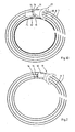
- the illustrated buffer conveyor comprises a frame, in this case provided with a central column 1 with a base 2 and a helical guide chute 3, which extends around the column and which is attached thereto. All kinds of other frame constructions are conceivable, of course.
- An end roller is mounted to the lower end 4 and the upper end 5 of the guide chute, and a return chute 6 of the frame extends between the ends of the helical guide chute 3.
- the guide chute 3 and the return chute 6 support a first elongated conveyor 7 and a second elongated conveyor 8, which may for example each be provided with one or more conveyor belts extending beside each other.
- the conveying portion and the return portion of the two conveyors 7, 8 move along different paths. Is also conceivable to use an embodiment in which the return portion is led along the underside of the guide chute 3 for the conveying portion.
- first and the second conveyor 7, 8 are possible, as long as a (preferably) more or less closed conveying surface is obtained.
- Examples of such conveyors are slat conveyors, link conveyors, stainless steel slat chain conveyors, textile belt conveyors, PVC belt conveyors, steel belt conveyors and the like, which latter types are generally only suitable for use in a straight, i.e. non-curved conveyor.
- the invention also extends to straight conveyors, however, to conveyors which are only curved in a horizontal plane, conveyors which (also) extend in vertical direction and conveyors not configured as endless conveyors, but for example as a roller conveyor or as an air conveyor or a magnetic conveyor.
- the helical chute 3 comprises 8 windings, but it is also possible to use a larger or a smaller number of windings, depending on the application in question.
- the use of guide rollers on the conveyors 7, 8 makes it possible to drive the conveyors over a large number of windings without any driving problem.
- the two conveyors 7, 8 each have their own drive motor 9, 10, which motors are mounted near the upper end roller 5 in this case, and which drive the associated conveyor belt 7, 8.
- the two conveyors may also be connected to supply or discharge conveyors and thus be driven and controlled by said conveyors.
- the two conveyors 7, 8 of Figs. 1A-1C (which each comprise two conveyor belts in the embodiment shown therein) can be driven independently of each other, in this case in opposite directions, i.e. products are conveyed upwards over the conveying surface of the first conveyor belts 7 from a supply end at the lower end 4, as indicated by the arrow P1, and downwards again over the conveying surface of the second conveyor belts 8 (see the arrow P2) towards a discharge end at the lower end 4.
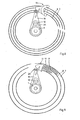
- the products are transferred from the conveying surface of the first conveyor belts 7 to the conveying surface of the second conveyor belts 8 by means of a transfer unit 11.
- the transfer unit 11 is movable within the buffer conveyor and is guided in the space between the first and the second conveyor.
- the position of the transfer unit 11 depends on the required buffering capacity between the supply end and the discharge end of the buffer conveyor. If the supply rate of the first conveyor 7 is higher than the discharge rate of the second conveyor 8, the excess of products being supplied must be buffered in the buffer conveyor, and the transfer unit 11 must move away from the supply end of the buffer conveyor in that case so as to collect more products on the buffer conveyor (see Figs. 1A-1C ). If in another case the supply rate of the first conveyor 7 is lower than the discharge rate of the second conveyor 8, the transfer unit 11 must move in the direction of the discharge end so as to supply buffered products to the discharge end.
- the buffer conveyor is for example capable of buffering a number of products which suffices for 5-15 minutes of buffering time, for example, which period of time generally suffices for restoring the balance between the supply rate and the discharge rate.
- the transfer unit 11 is provided with a drive unit for effecting the position change of the transfer unit 11 in the buffer conveyor, which drive unit preferably operates in dependence on the velocities of the first and the second conveyor 7, 8.
- Said drive unit for the transfer unit 11 comprises a drive motor 12, which follows at least the vertical movements of the transfer unit.
- Fig. 1D and Figs. 2-22 to be discussed hereinafter comprise various embodiments of buffer conveyors provided with transfer units 11 that can be driven in various ways.
- Fig. 1D shows a buffer conveyor according to Fig. 1 , in which the first conveyor 7, the second conveyor 8 and the transfer unit 11 provided with a drive motor 12 can be distinguished.
- the drive motor 12 is mounted to a mounting part 13, which is either rigidly or movably connected to the transfer unit 11, depending on the fact whether the curvature of the conveyor belts 7, 8 varies in the path along which the transfer unit can move, for example comprises straight and curved sections.
- the transfer unit 11 and the mounting part 13 can in that case rotate about an at least substantially vertical axis relative to each other.
- the drive motor 12 can adapt its position to the shape of the section in which the first and the second conveyor 7, 8 extend parallel to each other in case of a change in the curvature of said section.
- the drive motor 12 which may for example consist of an electric motor, is in engagement via the transmission 14 with a stationary part, in this case a ring gear 15 which is in engagement with a pinion 16 of the transmission 14. If the mounting part 13 is capable of movement relative to the transfer unit 11, the location where the pinion 16 engages the ring gear 15 is not critical.
- the drive motor 12 has a horizontal axis of rotation, so that the transmission 14 extends perpendicularly to a likewise horizontal, albeit transversely extending axis of rotation of the pinion 16.
- the transfer unit 11 comprises a transfer device 17 and a transfer element 18 for transferring the products from the first conveyor 7 to the second conveyor 8.
- the transfer device 17 in this case comprises a driven belt, which is known per se, for example from the priority document.
- the possible construction of the transfer element 18 is shown in the priority document.
- the transfer device 17 and the transfer element 18 are capable of transferring the products, which are to that end clamped between these two, from the first conveyor to the second conveyor.
- the drive motor 12 is directly rotatably mounted to the transfer unit 11.
- the pinion 16 of the transmission 14, which may or may not be provided with teeth, is not in engagement with a stationary ring gear or track in this case, but with one of the conveyors 7, 8 (in this case the conveyor 8), so that the movement with respect to one of the conveyors 7, 8 is directly effected.
- Figure 3 shows the embodiment in which the drive motor 12 is directly mounted to the transfer unit 11, with its axis of rotation extending at least substantially vertically.
- the drive motor is drivingly connected, via the transmission 14, which is configured as a drive belt in this case, to a gear or to a friction wheel 16, which is likewise rotatable about an at least substantially vertical axis and which is in engagement with the outer side of the column 1, which has a large diameter in this case.
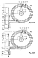
- Figure 4 shows a variant of the buffer conveyor, in which the transfer unit 11 is driven via an arm 19, which is on the one hand rotatably connected to the column 1 and which is drivingly connected to the transfer unit 11 at or near the other end.
- the arm 19 In the case of a transfer unit 11 that moves in vertical direction, the arm 19 is vertically movable with respect to the column 1, in such a manner that the arm 19 will remain at the same level as the transfer unit 11 during movement thereof along the helical path.
- the arm 19 can be moved in vertical direction via a separate driving mechanism, for example, but in this embodiment it is moved via a screw formed (in this case) by the helical path of the conveyors 7, 8.
- the arm 19 is to that end supported on the first conveyor 7 via a wheel 20.
- the gear on the outgoing shaft of the drive motor 12 is in engagement with a planet gear or ring gear 15, which is connected to the column 1, being locked against rotation but capable of vertical movement with respect thereto.
- Fig. 5 shows a variant of the preceding embodiment, in which the drive motor 12 is not mounted on the arm 19 and does not rotate along with the arm 19, either, and is fixedly connected to the column 1, locked against rotation but capable of vertical movement with respect thereto.
- the drive motor 12 may to that end be guided in vertical direction via a slide bearing, for example, which is connected to the arm 19.
- Fig. 5A shows another variant of the embodiment of Fig. 4 , in which the arm 19 is not vertically movable but extends above the uppermost winding or below the lowermost winding of the helically extending conveyors 7, 8, projecting beyond the outer circumference of the first conveyor 8 (or remaining within the inner circumference of the second conveyor belt 8).
- the arm 19 and the transfer unit 11 are in this case interconnected via a connecting element 21 which may vary in length so as to compensate for the difference in height between the arm 19 and the transfer unit 11.
- the position of the drive motor 12 is comparable to that shown in Fig. 4 , although in this case the arm 19, and thus the drive motor 12, are only capable of rotary movement and not of translatory movement with respect to the column 1.
- the embodiment of Fig. 5A is therefore not part of the present invention.
- Fig. 6 shows another variant of the embodiment of Fig. 4 , in which the conveyors 7 and 8 again extend in a helical path, which does not have a circular but rather an oval base shape, however.
- the arm 19 is to that end provided with means that enable the arm to adapt itself to the varying spacing between the transfer unit 11 and the column 1, which means comprise a telescopic arm portion 22 in this embodiment.
- Said telescopic arm portion 22 is connected to the transfer unit 11 in a manner which enables the arm portion 22 and the transfer unit 11 to pivot with respect to each other about an at least substantially vertical axis, for example via a vertical hinge 23.
- Fig. 7 shows a variant of the embodiment of Fig. 1D , the main difference being the fact that also in this case the helical path has an oval base shape and that the mounting element 13 with the drive motor 12 mounted thereon is connected to the transfer unit 11 via an at least substantially vertical hinge 24.
- Fig. 8 shows another variant of the embodiment of Fig. 4 , in which the drive motor 12 is mounted on the arm 19 in such a manner that the axis of rotation of the drive motor extends vertically, with the drive motor 12 being connected to the column 1 via a drive belt 25 and a pulley. Said pulley is in turn connected to the column 1, being locked against rotation but being vertically adjustable with respect thereto.
- Fig. 9 shows a variant of the embodiment of Fig. 8 , in which the transfer unit 11 has been adapted for transferring products P being conveyed in a mass flow.
- Products having a circular section are concerned in this case, such as bottles, pots or the like.
- the transfer device 17 of the transfer unit 11 may consist of a simple, non-movable guide, which functions to transfer products that come into contact with the guide of the transfer element 18 in lateral direction to the second conveyor 8.
- the guide of the transfer device 17 may also be moved in that case to help effect said transfer.
- Fig. 10 shows a variant comprising a movable transfer device 17 in the form of a circulating transfer belt moving from the first conveyor 7 to the second conveyor 8 on the side that faces towards the products.
- Fig. 11 shows a variant of the embodiment of Fig. 9 , in which a guide 26 is mounted to the conveyors 7, 8, thus moving along therewith, at the radial outer side and at the radial inner side, respectively, thereof for guiding the products.
- Fig. 12 shows another variant of the embodiment of Fig. 9 , in which a centre guide 27 extending parallel to the first conveyor 7 and the second conveyor 8 is provided between said conveyors. Said centre guide 27 follows the movements of the transfer unit 11.
- the centre guide 27 is to that end coupled to the transfer unit 11 or driven synchronously with the transfer unit 11.
- the end of the centre guide 27 facing towards the transfer device 17 is spaced a fixed distance therefrom, so that the products P present in the space between the centre guide 27 and the transfer device 17 can be transferred from the first conveyor 7 to the second conveyor 8.
- the centre guide 27 may be arranged in a small gap between the conveyors 7 and 8 or be suspended from a guide mounted above the conveyor belts 7 and 8.
- a transfer element 18 is attached to the end of the centre guide 27 that faces towards the transfer device 17.
- Said active transfer device 17 functions to help transfer the products P.
- the transfer element 18 may to that end be rotatable about one or more vertical axes, so that a kind of propeller is obtained, which actively transfers the products, but also an eccentrically reciprocating movement of the transfer element 18 is conceivable (a so-called "wagging unit"). Further variants are possible.
- the centre guide 27 provided with the transfer element 18, which may or may not be an active element, is combined with an active, in this case circulating transfer device 17.
- the centre guide 27 is arranged between the first conveyor 7 and the second conveyor 8, and the gap thus formed is provided with a flexible bridge element at the area between the transfer device 17 and the transfer element 18, the upper surface of which bridge element lies in the same plane as the conveying surface of the first and the second conveyor 7, 8, so that the products can be transferred from the first conveyor 7 to the second conveyor 8 via the flexible bridge element 28.
- the bridge element 28 may be integral with the centre guide 27 or consist of a separate element, which is connected either to the transfer unit 11 or to the centre guide 27 for following the movements of the transfer unit 11 at least along part of the conveyor path.
- Fig. 15 shows a variant of the embodiment shown in Fig. 10 , in which the first conveyor 7 and the second conveyor 8 are spaced apart by a small distance and in which a stationary bridge element 29 is disposed in the small gap between the conveyors, which bridge element extends along at least part of the conveyor path, parallel thereto.
- the surface of the bridge element 29 in turn lies in at least substantially the same plane as the conveying surface of the conveyors 7 and 8. In this case the products present near the transfer unit 11 move from the first conveyor 7 to the second conveyor 8 via the stationary bridge element 29.
- Fig. 16 is a view of a variant of the embodiment shown in Fig. 14 , which shows the manner in which the active transfer element 18 can be driven.
- the transfer element 18 is driven by drive means 31 visa a drive belt 30.
- Said drive means 31 may be a drive motor or be connected to the two conveyors 7, 8, for example via a differential, for being driven in dependence on the difference in velocity between the first and the second conveyor 7, 8.
- the drive means 31 may also be driven by one of the conveyors 7, 8.
- the drive means 31 is also used for driving the transfer device 17.
- Fig. 17 is a view of an embodiment corresponding to the embodiment of Fig. 4 , in which the means 31 for driving the transfer device 17 is shown.
- the transfer belt of the transfer device 17 is to that end passed over the drive means 31.
- Fig. 18 shows that in this embodiment the drive means 31 can also be used for driving the transfer element 18 disposed opposite the transfer device 17.
- Fig. 19 shows the manner in which the drive motor 12 for the transfer unit 11 can be controlled.
- Fig. 19 shows a control unit 32 which is on the one hand connected to the drive motor 12 and which is on the other hand connected to sensors 33 that determine the velocities of the first and the second conveyor 7, 8, directly at the conveyor belts thereof or via the driving gear thereof. Based on the detections made by the sensors 33, the control unit calculates the required speed for the drive motor 12. This takes place on the basis of a formula in which the difference in velocity between the first conveyor 7 and the second conveyor 8 and possibly a (varying) factor play a part.
- the control unit 34 may also be connected to the drive means 31, a drive motor in this case, for the transfer device 17 and the transfer element 18.
- Said drive means 31, too, may be controlled on the basis of the information obtained from the sensors 33.
- an associated energy source in particular the electricity mains
- use may be made of sliding contacts which extend substantially parallel to the path of the conveyors 7, 8, but it is also possible to make use of a rotary connection, with the cables extending from the column 1 to the drive motors 12, 31, for example.
- the connection between the control unit 32 and the drive motors 12 and 31 may take place in the same manner or, for example, via a radio signal or through induction.
- Fig. 20a shows an embodiment in which the first and the second conveyor are connected to a supply conveyor 34 and a discharge conveyor 35, which are integrated in this embodiment.
- Sensors 36 and 37 measure the amount of products present on the supply conveyor 34 and the discharge conveyor 35 (no supply or discharge, enough supply or discharge or too much supply or discharge) and the control unit 32 controls the drive motors 9 and 10 of the first and the second conveyor 7, 8, the drive motor 12 of the transfer unit 11 and/or the drive means 31 of the transfer device 17 (partially) on the basis of the measurement data.
- Fig. 20b the supply conveyor 34 and the discharge conveyor 35 are not connected, and the control unit 32 also controls motors 38 and 39 of the supply conveyor and the discharge conveyor, optimally gearing the various conveying links in the system to each other so as to tune the transportation to the preceding or next, likewise monitored processing or treatment processes in the line.
- control unit 32 and the sensors 33 are mounted on or to the transfer unit 11, so that the communication and the connections are significantly simplified. If the energy source is mounted to the transfer unit 11 as well, for example in the form of a battery, the transfer unit 11 can function independently. In this case the sensors 33 do not measure the absolute velocity of the conveyors 7, 8, but the velocity thereof in relation to the transfer unit 11, and the required velocity of the transfer unit 11 can be calculated on the basis of said measurement.
- Fig. 22 shows another variant of the transfer unit 11, which is in particular intended for transferring products P which are large, for example, or which, because of their shape, cannot be moved by the continuously circulated transfer unit.
- a "flap belt" pusher is used as the transfer device 17, but it is also possible to use a rod pusher or the like.
- the transfer device 17 makes a discontinuous stroke, and such a stroke is only made if the sensor detects the presence of a product near the transfer device 17.
- the transfer device 17 will then make a transferring movement, and in the illustrated embodiment, which makes use of a circulating belt for moving the pushers, the transfer device will directly be ready for transferring a next product P.
- the stroke of the transfer device may also be initiated by a computer calculation as known from tracing systems.
- the invention provides a buffer conveyor which can be embodied in a variety of ways and which provides a versatile manner of transferring products.
- the drive of the transfer unit can be readily adapted to the application in question.
- the various embodiments may be combined, if desired, so that specific features of one embodiment can also be integrated in another embodiment.
Landscapes
- Engineering & Computer Science (AREA)
- Mechanical Engineering (AREA)
- Branching, Merging, And Special Transfer Between Conveyors (AREA)
- Structure Of Belt Conveyors (AREA)
- Intermediate Stations On Conveyors (AREA)
- Attitude Control For Articles On Conveyors (AREA)
- Relays Between Conveyors (AREA)
Claims (14)
- Convoyeur tampon dévolu au transport et à l'amortissement de produits, comprenant
au moins un premier convoyeur (7) de forme allongée, qui peut être entraîné dans une première direction et présente une extrémité d'alimentation,
un second convoyeur (8) de forme allongée, qui peut être entraîné dans une seconde direction opposée et présente une extrémité de décharge, lesquels premier et second convoyeurs s'étendent sur un trajet offrant, au moins substantiellement, un parallélisme mutuel et une juxtaposition réciproque, ledit trajet étant courbe, au moins dans le plan horizontal, et s'étendant également dans une direction verticale, au moins en partie, et
une unité de transfert (11) qui est mobile, au moins pour l'essentiel, parallèlement aux premier et second convoyeurs, sur le trajet précité, et est pourvue d'un dispositif de transfert (17) conçu pour transférer les produits du premier convoyeur au second convoyeur, laquelle unité de transfert comprend une unité d'entraînement destinée à mouvoir ladite unité de transfert, de préférence en fonction des vitesses desdits premier et second convoyeurs,
caractérisé par le fait que l'unité d'entraînement de l'unité de transfert comprend un moteur d'entraînement (12) qui est relié à ladite unité de transfert (11), de manière à suivre au moins les mouvements verticaux de ladite unité de transfert. - Convoyeur tampon selon la revendication 1, dans lequel le moteur d'entraînement (12) est monté sur un élément de montage (13) qui se meut conjointement à l'unité de transfert, ledit élément de montage (13) étant monté, de préférence, sur ou contre ladite unité de transfert (11).
- Convoyeur tampon selon l'une quelconque des revendications précédentes, dans lequel l'unité d'entraînement comprend une transmission (14) qui est en prise d'entraînement, d'une part, avec le moteur d'entraînement (12) et, d'autre part, soit avec le bâti (1-3), soit avec le(s) premier et/ou second convoyeur(s) (7, 8).
- Convoyeur tampon selon l'une quelconque des revendications précédentes, dans lequel le trajet de convoyage s'enroule autour d'une colonne verticale (1) à laquelle un bras (19) est relié, lequel bras est relié à ladite colonne par l'une des extrémités, avec faculté de pivotement, et est relié à l'unité de transfert (11) par l'autre extrémité.
- Convoyeur tampon selon la revendication 4, dans lequel le moteur d'entraînement (12) est relié au bras (19), de préférence monté sur ledit bras, et est en prise d'entraînement avec la colonne (1).
- Convoyeur tampon selon la revendication 4 ou 5, dans lequel le trajet de convoyage s'étend de manière non concentrique à la colonne (1) ; et dans lequel le bras (19) est doté de moyens conçus pour adapter ledit bras à la distance variable entre l'unité de transfert (11) et ladite colonne.
- Convoyeur tampon selon l'une quelconque des revendications précédentes, dans lequel ledit trajet présente une courbure spiroïdale ou hélicoïdale, et peut offrir des courbures qui varient sur la longueur dudit trajet.
- Convoyeur tampon selon l'une quelconque des revendications précédentes, dans lequel les premier et second convoyeurs (7, 8) s'étendent, sur ledit trajet, en étant séparés l'un de l'autre par un espace interstitiel horizontal ; et dans lequel l'unité de transfert (11) est guidée sur un guide, dans ledit espace interstitiel, de façon telle que les produits soient transférés dudit premier convoyeur audit second convoyeur par l'intermédiaire de ladite unité de transfert.
- Convoyeur tampon selon l'une quelconque des revendications 1-7, dans lequel les premier et second convoyeurs (7, 8) s'étendent, sur ledit trajet, substantiellement sans aucun espace interstitiel les séparant, de telle sorte que les produits soient transférés directement dudit premier convoyeur audit second convoyeur, au moyen de l'unité de transfert (11) ; et dans lequel un guide central (27) est prévu, de préférence, au niveau ou au-dessus de la transition entre lesdits premier et second convoyeurs (7, 8), lequel guide central est couplé au mouvement de l'unité de transfert (11) et s'achève en un point éloigné, d'une certaine distance, du dispositif de transfert (17) de ladite unité de transfert.
- Convoyeur tampon selon la revendication 9, dans lequel un élément de transfert (18) est monté sur l'extrémité du guide central (27) qui pointe dans la direction du dispositif de transfert (17) de l'unité de transfert (11), lequel élément de transfert (18) peut être entraîné en vue de transférer, du premier convoyeur (7) au second convoyeur (8), des produits qui sont enserrés, à cette extrémité, entre ledit dispositif de transfert (17) et ledit élément de transfert (18).
- Convoyeur tampon selon l'une quelconque des revendications précédentes, dans lequel le dispositif de transfert (17) peut être entraîné, par exemple par des moyens d'entraînement (31) reliés à l'unité de transfert (11).
- Convoyeur tampon selon les revendications 10 et 11, dans lequel l'élément de transfert (18) et le dispositif de transfert (17) peuvent être entraînés par les mêmes moyens d'entraînement (31).
- Convoyeur tampon selon l'une quelconque des revendications précédentes, dans lequel l'unité de transfert (11) est entraînée en fonction des vitesses des premier et second convoyeurs (7, 8), ledit convoyeur tampon étant pourvu, à cette fin, de capteurs (33) affectés à la mesure desdites vitesses, et d'une unité de commande (32) destinée à commander la manière dont ladite unité de transfert est entraînée sur la base des vitesses ainsi mesurées ; et dans lequel, de préférence, lesdits capteurs (33) sont connectés à l'unité de transfert (11) et mesurent les vitesses desdits premier et second convoyeurs (7, 8) par rapport à celle de ladite unité de transfert.
- Convoyeur tampon selon l'une quelconque des revendications précédentes, dans lequel le moteur d'entraînement (12), se mouvant au moins en partie conjointement à l'unité de transfert, est raccordé à une source d'énergie se mouvant conjointement à ladite unité de transfert (11), telle qu'une batterie par exemple, ou à une source stationnaire d'énergie par l'intermédiaire de contacts glissants, de câbles ou d'éléments similaires l'accompagnant dans ses mouvements.
Priority Applications (1)
| Application Number | Priority Date | Filing Date | Title |
|---|---|---|---|
| EP07747398A EP2010442B1 (fr) | 2006-04-24 | 2007-04-20 | Convoyeur tampon pour transporter et séparer des produits |
Applications Claiming Priority (4)
| Application Number | Priority Date | Filing Date | Title |
|---|---|---|---|
| EP06112987A EP1849725B1 (fr) | 2006-04-24 | 2006-04-24 | Conveyeur pour transporter et accumuler des produits individuels |
| NL2000319A NL2000319C2 (nl) | 2006-04-24 | 2006-11-20 | Buffertransporteur voor het transporteren en bufferen van producten. |
| EP07747398A EP2010442B1 (fr) | 2006-04-24 | 2007-04-20 | Convoyeur tampon pour transporter et séparer des produits |
| PCT/NL2007/050174 WO2007123401A1 (fr) | 2006-04-24 | 2007-04-20 | Convoyeur tampon pour transporter et séparer des produits |
Publications (2)
| Publication Number | Publication Date |
|---|---|
| EP2010442A1 EP2010442A1 (fr) | 2009-01-07 |
| EP2010442B1 true EP2010442B1 (fr) | 2011-04-06 |
Family
ID=36607280
Family Applications (2)
| Application Number | Title | Priority Date | Filing Date |
|---|---|---|---|
| EP06112987A Active EP1849725B1 (fr) | 2006-04-24 | 2006-04-24 | Conveyeur pour transporter et accumuler des produits individuels |
| EP07747398A Active EP2010442B1 (fr) | 2006-04-24 | 2007-04-20 | Convoyeur tampon pour transporter et séparer des produits |
Family Applications Before (1)
| Application Number | Title | Priority Date | Filing Date |
|---|---|---|---|
| EP06112987A Active EP1849725B1 (fr) | 2006-04-24 | 2006-04-24 | Conveyeur pour transporter et accumuler des produits individuels |
Country Status (11)
| Country | Link |
|---|---|
| US (1) | US8042676B2 (fr) |
| EP (2) | EP1849725B1 (fr) |
| JP (1) | JP2009536601A (fr) |
| KR (1) | KR20080112230A (fr) |
| CN (1) | CN101374739B (fr) |
| AT (1) | ATE504527T1 (fr) |
| CA (1) | CA2633021A1 (fr) |
| DE (2) | DE602006003532D1 (fr) |
| ES (1) | ES2363101T3 (fr) |
| NL (1) | NL2000319C2 (fr) |
| WO (1) | WO2007123401A1 (fr) |
Families Citing this family (22)
| Publication number | Priority date | Publication date | Assignee | Title |
|---|---|---|---|---|
| NL2000404C2 (nl) | 2006-12-22 | 2008-06-25 | Ambaflex Internat B V | Transportinrichting. |
| DE102008004775A1 (de) * | 2008-01-16 | 2009-07-23 | Krones Ag | Vorrichtung zum Transportieren von Gegenständen |
| NL1035783C2 (nl) | 2008-08-04 | 2010-02-05 | Jan Willem Takens | Buffertransporteur voor het transporteren en bufferen van producten. |
| NL2001875C2 (nl) * | 2008-08-06 | 2010-02-09 | Specialty Conveyor Bv | Buffertransporteur voor het transporteren en bufferen van producten. |
| DE102008037188A1 (de) | 2008-08-11 | 2010-02-18 | Krones Ag | Vorrichtung und Verfahren zum Bilden von Stückgüterzusammenstellungen |
| NL2002100C (en) | 2008-10-15 | 2010-04-16 | Specialty Conveyor Bv | A buffer conveyor having parallel tracks. |
| NL2002878C2 (en) * | 2009-05-13 | 2010-11-18 | Ambaflex Internat B V | A conveyor having parallel conveyor members. |
| CN101559882B (zh) * | 2009-05-21 | 2011-11-23 | 东华大学 | 一种多层式堆栈缓冲设备 |
| DE102011001532A1 (de) | 2010-07-30 | 2012-02-02 | Krones Aktiengesellschaft | Speichervorrichtung für Behälter und Verfahren zum Speichern von Behältern |
| EP2428470B1 (fr) * | 2010-09-08 | 2013-03-13 | Krones AG | Convoyeur |
| NL2005846C2 (en) | 2010-12-09 | 2012-06-12 | Specialty Conveyor Bv | A transfer conveyor and a conveying system. |
| DE102011080441B4 (de) | 2011-08-04 | 2023-01-12 | Krones Aktiengesellschaft | Speichervorrichtung für eine Abfüllanlage und Getränkeabfüllanlage mit einer solchen Speichervorrichtung |
| DE202012104466U1 (de) * | 2012-11-19 | 2013-05-28 | Krones Ag | Vorrichtung zum Bereitstellen von Formteilen in einer Getränkeabfüllanlage |
| CN103935681B (zh) * | 2014-03-18 | 2016-01-20 | 杭州中亚瑞程包装科技有限公司 | 一种旁通暂存式输送缓冲装置及缓冲输送方法 |
| NL2013820B1 (en) * | 2014-11-17 | 2016-10-10 | Polyketting Holding B V | Accumulator device for dynamically accumulating conveyed products, as well as a method for using such a device. |
| CN104407162B (zh) * | 2014-12-19 | 2016-01-13 | 长沙开元仪器股份有限公司 | 红外测硫仪及其坩埚滑台 |
| US9688482B2 (en) | 2015-03-17 | 2017-06-27 | Illinois Tool Works Inc. | Apparatus for buffering the flow of articles |
| PL238000B1 (pl) * | 2015-04-20 | 2021-06-28 | Int Tobacco Machinery Poland Spolka Z Ograniczona Odpowiedzialnoscia | Urządzenie podtrzymujące przepływ masowy elementów prętopodobnych przemysłu tytoniowego w kanale transportowym oraz sposób napełniania oraz opróżniania kanału transportowego |
| US9688479B1 (en) * | 2015-09-21 | 2017-06-27 | Amazon Technologies, Inc. | Multiple speed conveyor storage system |
| DE102016102474A1 (de) * | 2016-02-12 | 2017-08-17 | Hauni Maschinenbau Gmbh | Vorrichtung zum Fördern eines Massenstroms stabförmiger Artikel und Verwendung derselben |
| CN106542482A (zh) * | 2016-10-21 | 2017-03-29 | 张家港市万金机械有限公司 | 一种全自动灌装封口一体机 |
| CN111408508B (zh) * | 2020-04-03 | 2021-05-25 | 涡阳县康仕达机电有限公司 | 一种车桥轮毂涂装用烘干装置 |
Family Cites Families (45)
| Publication number | Priority date | Publication date | Assignee | Title |
|---|---|---|---|---|
| DE1262886B (de) | 1964-12-04 | 1968-03-07 | Bahlsen Werner | Zwischenspeicher im Foerderweg von flachen, senkrecht aneinanderliegenden Gebaeckstuecken |
| US3318439A (en) * | 1965-04-12 | 1967-05-09 | Kornylac Co | Conveyor system |
| DE2307728A1 (de) | 1973-02-16 | 1974-09-05 | Windmoeller & Hoelscher | Einrichtung zur herstellung von einseitig offenen, am bodenende abgenaehten saecken |
| US4018325A (en) * | 1975-10-09 | 1977-04-19 | The Pillsbury Company | Automatic package accumulator |
| DE2618905C3 (de) | 1976-04-29 | 1980-09-25 | Maschinenfabrik Alfred Schmermund Gmbh & Co, 5820 Gevelsberg | Zwischenspeicher in Form eines Übergabe-Förderers |
| US4063632A (en) * | 1976-06-23 | 1977-12-20 | Columbia Machine, Inc. | Swingable arcuate guide for selectively orienting articles |
| CH618398A5 (fr) * | 1977-06-06 | 1980-07-31 | Ferag Ag | |
| US6497321B2 (en) * | 2001-03-09 | 2002-12-24 | Hartness International, Inc. | Apparatus for diverting a stream of articles |
| US4364465A (en) * | 1980-09-19 | 1982-12-21 | Nabisco, Inc. | Collating conveyor system |
| FR2499033A1 (fr) * | 1981-02-03 | 1982-08-06 | Nantaise Biscuiterie | Procede et dispositif pour regulariser le transfert de produits solides identiques |
| US4413724A (en) * | 1981-05-18 | 1983-11-08 | Mapatent, N.V. | Horizontal accumulator |
| US4513858A (en) * | 1981-05-18 | 1985-04-30 | Mapatent, N.V. | Horizontal accumulator |
| US4401020A (en) * | 1981-12-16 | 1983-08-30 | Seaco Industries | Vegetable banding apparatus |
| FR2524436B1 (fr) * | 1982-04-02 | 1985-09-27 | Nantaise Biscuiterie | Dispositif regulateur de transfert de produits solides identiques entre des machines amont et aval de vitesses differentes |
| JPS5953315A (ja) * | 1982-09-22 | 1984-03-28 | Toyo Kanetsu Kk | コンベヤ装置 |
| CH667258A5 (de) * | 1985-05-02 | 1988-09-30 | Ferag Ag | Verfahren und vorrichtung zum beschicken einer vereinzelungseinrichtung fuer druckprodukte, insbesondere eines anlegers. |
| DE3774048D1 (de) | 1986-09-08 | 1991-11-28 | Ferag Ag | Verfahren und vorrichtung zum vergleichmaessigen des abstandes zwischen aufeinanderfolgenden, in einer schuppenformation anfallenden produkten, insbesondere druckererzeugnissen. |
| JPH0736898Y2 (ja) * | 1987-02-19 | 1995-08-23 | エービー テトラパック | コンベヤにおける搬送物品の配分移送装置 |
| DE3742955A1 (de) * | 1987-12-18 | 1989-06-29 | Focke & Co | Einrichtung zum herstellen und verpacken von zigaretten |
| US4924998A (en) * | 1988-11-10 | 1990-05-15 | The Boeing Company | Storage mechanism for sorted articles |
| US4989718A (en) * | 1989-08-23 | 1991-02-05 | Hartness International, Inc. | Surge control method and apparatus |
| US5067857A (en) * | 1990-04-27 | 1991-11-26 | Coors Brewing Company | Apparatus for diverting the movement of cylindrical bodies |
| US5413213A (en) * | 1992-07-25 | 1995-05-09 | Korber Ag | Apparatus for transporting mass flows of articles |
| US5690463A (en) * | 1992-07-31 | 1997-11-25 | Nippon Filing Co., Ltd. | Book storage/retrieval apparatus |
| DE4325380C2 (de) | 1993-07-24 | 1996-02-08 | Schierholz Kg Louis | Hänge-Fördersystem |
| US5350050A (en) * | 1993-09-09 | 1994-09-27 | Donald L. Collver | Continuous vertical conveyor |
| DE9406061U1 (de) * | 1994-04-12 | 1995-08-10 | Mts Modulare Transport Systeme Gmbh, Vomp | Sortieranlage zum Sortieren von einzeln geförderten Gegenständen |
| US5417317A (en) * | 1994-04-29 | 1995-05-23 | Atlas Pacific Engineering Company | Apparatus for segregating and feeding fruit from a bulk supply |
| DE4416893C1 (de) * | 1994-05-13 | 1995-06-14 | Licentia Gmbh | Leitvorrichtung für Verteilfördereinrichtung |
| DK172491B1 (da) * | 1994-10-14 | 1998-10-05 | Gram As | Anlæg samt fremgangsmåde til midlertidig lagring af emner samt anvendelse af et sådant anlæg |
| CH690646A5 (de) * | 1995-05-09 | 2000-11-30 | Ferag Ag | Vorrichtung zum Fördern von Gegenständen. |
| SE504804C2 (sv) * | 1995-08-24 | 1997-04-28 | Swedefish Machinery Ab | Anordning för överföring av föremål från en första till en andra transportör |
| US5903464A (en) * | 1997-03-07 | 1999-05-11 | Stingel, Jr.; Frederick John | Conveying system and method for mixing stacked articles |
| FR2766803A1 (fr) * | 1997-07-31 | 1999-02-05 | Diaz Jose Arriaza | Accumulateur |
| US6152291A (en) * | 1998-03-09 | 2000-11-28 | Hartness International | Apparatus for controlling the flow of articles |
| US6260688B1 (en) * | 1999-01-22 | 2001-07-17 | Hartness International | Apparatus for controlling the flow of articles |
| US6325198B1 (en) * | 1998-06-26 | 2001-12-04 | Eveready Battery Company, Inc. | High speed manufacturing system |
| US6241074B1 (en) * | 1999-07-30 | 2001-06-05 | Hartness International, Inc. | Guide device for transferring articles between conveyors |
| US6182812B1 (en) * | 1999-07-30 | 2001-02-06 | Hartness International | Device for transferring articles between oppositely running conveyors |
| US6230874B1 (en) * | 1999-12-07 | 2001-05-15 | Hartness International | Apparatus for controlling the flow of articles |
| US6334528B1 (en) * | 2000-06-16 | 2002-01-01 | The Laitram Corporation | Variable-width spacer |
| US6612420B1 (en) * | 2000-10-17 | 2003-09-02 | Hartness International, Inc. | Device for transferring articles between oppositely running conveyors |
| US6533103B2 (en) * | 2001-07-27 | 2003-03-18 | Hartness International | Transfer device for use between two conveyors |
| US6713107B2 (en) * | 2002-03-01 | 2004-03-30 | Conagra Foods, Inc. | Airflow distribution systems for food processors |
| DE202004016069U1 (de) * | 2004-10-16 | 2005-12-01 | Krones Ag | Vorrichtung zum Puffern von Gegenständen |
-
2006
- 2006-04-24 EP EP06112987A patent/EP1849725B1/fr active Active
- 2006-04-24 DE DE602006003532T patent/DE602006003532D1/de active Active
- 2006-11-20 NL NL2000319A patent/NL2000319C2/nl not_active IP Right Cessation
-
2007
- 2007-04-20 JP JP2009507605A patent/JP2009536601A/ja active Pending
- 2007-04-20 WO PCT/NL2007/050174 patent/WO2007123401A1/fr active Application Filing
- 2007-04-20 ES ES07747398T patent/ES2363101T3/es active Active
- 2007-04-20 AT AT07747398T patent/ATE504527T1/de not_active IP Right Cessation
- 2007-04-20 EP EP07747398A patent/EP2010442B1/fr active Active
- 2007-04-20 CA CA002633021A patent/CA2633021A1/fr not_active Abandoned
- 2007-04-20 DE DE602007013735T patent/DE602007013735D1/de active Active
- 2007-04-20 KR KR1020087022384A patent/KR20080112230A/ko not_active Application Discontinuation
- 2007-04-20 CN CN2007800034082A patent/CN101374739B/zh active Active
-
2008
- 2008-10-24 US US12/257,629 patent/US8042676B2/en active Active
Also Published As
| Publication number | Publication date |
|---|---|
| DE602007013735D1 (de) | 2011-05-19 |
| CA2633021A1 (fr) | 2007-11-01 |
| EP2010442A1 (fr) | 2009-01-07 |
| EP1849725A1 (fr) | 2007-10-31 |
| WO2007123401A1 (fr) | 2007-11-01 |
| DE602006003532D1 (de) | 2008-12-18 |
| JP2009536601A (ja) | 2009-10-15 |
| CN101374739B (zh) | 2012-05-30 |
| EP1849725B1 (fr) | 2008-11-05 |
| KR20080112230A (ko) | 2008-12-24 |
| US8042676B2 (en) | 2011-10-25 |
| CN101374739A (zh) | 2009-02-25 |
| ATE504527T1 (de) | 2011-04-15 |
| ES2363101T3 (es) | 2011-07-20 |
| NL2000319C2 (nl) | 2007-10-25 |
| US20090050445A1 (en) | 2009-02-26 |
Similar Documents
| Publication | Publication Date | Title |
|---|---|---|
| EP2010442B1 (fr) | Convoyeur tampon pour transporter et séparer des produits | |
| CN102482038B (zh) | 用来在缓冲区域中运送和累积物品的设备 | |
| CN101918294B (zh) | 用于输送物体的装置 | |
| US20090314610A1 (en) | Transfer device for a transport system | |
| US20160052726A1 (en) | Conveyor Accumulator for Controlling the Flow of Articles Being Conveyed | |
| EP2310305B1 (fr) | Convoyeur tampon pour transporter et stocker temporairement des produits | |
| JP2002535217A (ja) | 物品の流れを制御する装置 | |
| EP2074045B1 (fr) | Transporteur pour le transport et le stockage tampon d'articles | |
| US20110259713A1 (en) | Spiral conveyor apparatus with automatic flow control and merge/divert attachment | |
| US20110180373A1 (en) | Buffer conveyor for conveying and buffering products | |
| US20080093197A1 (en) | Dynamic Conveyance Device | |
| EP3085645B1 (fr) | Appareil pour transporter des objets | |
| US10000344B2 (en) | Product flow regulator | |
| NL2000324C1 (nl) | Buffertransporteur. |
Legal Events
| Date | Code | Title | Description |
|---|---|---|---|
| PUAI | Public reference made under article 153(3) epc to a published international application that has entered the european phase |
Free format text: ORIGINAL CODE: 0009012 |
|
| 17P | Request for examination filed |
Effective date: 20080911 |
|
| AK | Designated contracting states |
Kind code of ref document: A1 Designated state(s): AT BE BG CH CY CZ DE DK EE ES FI FR GB GR HU IE IS IT LI LT LU LV MC MT NL PL PT RO SE SI SK TR |
|
| AX | Request for extension of the european patent |
Extension state: AL BA HR MK RS |
|
| 17Q | First examination report despatched |
Effective date: 20091116 |
|
| GRAP | Despatch of communication of intention to grant a patent |
Free format text: ORIGINAL CODE: EPIDOSNIGR1 |
|
| GRAS | Grant fee paid |
Free format text: ORIGINAL CODE: EPIDOSNIGR3 |
|
| GRAA | (expected) grant |
Free format text: ORIGINAL CODE: 0009210 |
|
| AK | Designated contracting states |
Kind code of ref document: B1 Designated state(s): AT BE BG CH CY CZ DE DK EE ES FI FR GB GR HU IE IS IT LI LT LU LV MC MT NL PL PT RO SE SI SK TR |
|
| REG | Reference to a national code |
Ref country code: GB Ref legal event code: FG4D |
|
| REG | Reference to a national code |
Ref country code: CH Ref legal event code: EP |
|
| REG | Reference to a national code |
Ref country code: IE Ref legal event code: FG4D |
|
| REF | Corresponds to: |
Ref document number: 602007013735 Country of ref document: DE Date of ref document: 20110519 Kind code of ref document: P |
|
| REG | Reference to a national code |
Ref country code: DE Ref legal event code: R096 Ref document number: 602007013735 Country of ref document: DE Effective date: 20110519 |
|
| REG | Reference to a national code |
Ref country code: NL Ref legal event code: T3 |
|
| REG | Reference to a national code |
Ref country code: ES Ref legal event code: FG2A Ref document number: 2363101 Country of ref document: ES Kind code of ref document: T3 Effective date: 20110720 |
|
| PG25 | Lapsed in a contracting state [announced via postgrant information from national office to epo] |
Ref country code: SI Free format text: LAPSE BECAUSE OF FAILURE TO SUBMIT A TRANSLATION OF THE DESCRIPTION OR TO PAY THE FEE WITHIN THE PRESCRIBED TIME-LIMIT Effective date: 20110406 |
|
| LTIE | Lt: invalidation of european patent or patent extension |
Effective date: 20110406 |
|
| PG25 | Lapsed in a contracting state [announced via postgrant information from national office to epo] |
Ref country code: PT Free format text: LAPSE BECAUSE OF FAILURE TO SUBMIT A TRANSLATION OF THE DESCRIPTION OR TO PAY THE FEE WITHIN THE PRESCRIBED TIME-LIMIT Effective date: 20110808 Ref country code: SE Free format text: LAPSE BECAUSE OF FAILURE TO SUBMIT A TRANSLATION OF THE DESCRIPTION OR TO PAY THE FEE WITHIN THE PRESCRIBED TIME-LIMIT Effective date: 20110406 Ref country code: LT Free format text: LAPSE BECAUSE OF FAILURE TO SUBMIT A TRANSLATION OF THE DESCRIPTION OR TO PAY THE FEE WITHIN THE PRESCRIBED TIME-LIMIT Effective date: 20110406 |
|
| PG25 | Lapsed in a contracting state [announced via postgrant information from national office to epo] |
Ref country code: LV Free format text: LAPSE BECAUSE OF FAILURE TO SUBMIT A TRANSLATION OF THE DESCRIPTION OR TO PAY THE FEE WITHIN THE PRESCRIBED TIME-LIMIT Effective date: 20110406 Ref country code: IS Free format text: LAPSE BECAUSE OF FAILURE TO SUBMIT A TRANSLATION OF THE DESCRIPTION OR TO PAY THE FEE WITHIN THE PRESCRIBED TIME-LIMIT Effective date: 20110806 Ref country code: MC Free format text: LAPSE BECAUSE OF NON-PAYMENT OF DUE FEES Effective date: 20110430 Ref country code: GR Free format text: LAPSE BECAUSE OF FAILURE TO SUBMIT A TRANSLATION OF THE DESCRIPTION OR TO PAY THE FEE WITHIN THE PRESCRIBED TIME-LIMIT Effective date: 20110707 Ref country code: AT Free format text: LAPSE BECAUSE OF FAILURE TO SUBMIT A TRANSLATION OF THE DESCRIPTION OR TO PAY THE FEE WITHIN THE PRESCRIBED TIME-LIMIT Effective date: 20110406 Ref country code: CY Free format text: LAPSE BECAUSE OF FAILURE TO SUBMIT A TRANSLATION OF THE DESCRIPTION OR TO PAY THE FEE WITHIN THE PRESCRIBED TIME-LIMIT Effective date: 20110406 Ref country code: FI Free format text: LAPSE BECAUSE OF FAILURE TO SUBMIT A TRANSLATION OF THE DESCRIPTION OR TO PAY THE FEE WITHIN THE PRESCRIBED TIME-LIMIT Effective date: 20110406 |
|
| REG | Reference to a national code |
Ref country code: CH Ref legal event code: PL |
|
| PG25 | Lapsed in a contracting state [announced via postgrant information from national office to epo] |
Ref country code: MT Free format text: LAPSE BECAUSE OF FAILURE TO SUBMIT A TRANSLATION OF THE DESCRIPTION OR TO PAY THE FEE WITHIN THE PRESCRIBED TIME-LIMIT Effective date: 20110406 |
|
| PG25 | Lapsed in a contracting state [announced via postgrant information from national office to epo] |
Ref country code: EE Free format text: LAPSE BECAUSE OF FAILURE TO SUBMIT A TRANSLATION OF THE DESCRIPTION OR TO PAY THE FEE WITHIN THE PRESCRIBED TIME-LIMIT Effective date: 20110406 Ref country code: CH Free format text: LAPSE BECAUSE OF NON-PAYMENT OF DUE FEES Effective date: 20110430 Ref country code: LI Free format text: LAPSE BECAUSE OF NON-PAYMENT OF DUE FEES Effective date: 20110430 Ref country code: CZ Free format text: LAPSE BECAUSE OF FAILURE TO SUBMIT A TRANSLATION OF THE DESCRIPTION OR TO PAY THE FEE WITHIN THE PRESCRIBED TIME-LIMIT Effective date: 20110406 |
|
| REG | Reference to a national code |
Ref country code: IE Ref legal event code: MM4A |
|
| PLBE | No opposition filed within time limit |
Free format text: ORIGINAL CODE: 0009261 |
|
| STAA | Information on the status of an ep patent application or granted ep patent |
Free format text: STATUS: NO OPPOSITION FILED WITHIN TIME LIMIT |
|
| PG25 | Lapsed in a contracting state [announced via postgrant information from national office to epo] |
Ref country code: PL Free format text: LAPSE BECAUSE OF FAILURE TO SUBMIT A TRANSLATION OF THE DESCRIPTION OR TO PAY THE FEE WITHIN THE PRESCRIBED TIME-LIMIT Effective date: 20110406 Ref country code: SK Free format text: LAPSE BECAUSE OF FAILURE TO SUBMIT A TRANSLATION OF THE DESCRIPTION OR TO PAY THE FEE WITHIN THE PRESCRIBED TIME-LIMIT Effective date: 20110406 Ref country code: RO Free format text: LAPSE BECAUSE OF FAILURE TO SUBMIT A TRANSLATION OF THE DESCRIPTION OR TO PAY THE FEE WITHIN THE PRESCRIBED TIME-LIMIT Effective date: 20110406 Ref country code: DK Free format text: LAPSE BECAUSE OF FAILURE TO SUBMIT A TRANSLATION OF THE DESCRIPTION OR TO PAY THE FEE WITHIN THE PRESCRIBED TIME-LIMIT Effective date: 20110406 |
|
| 26N | No opposition filed |
Effective date: 20120110 |
|
| PG25 | Lapsed in a contracting state [announced via postgrant information from national office to epo] |
Ref country code: IE Free format text: LAPSE BECAUSE OF NON-PAYMENT OF DUE FEES Effective date: 20110420 |
|
| REG | Reference to a national code |
Ref country code: DE Ref legal event code: R097 Ref document number: 602007013735 Country of ref document: DE Effective date: 20120110 |
|
| PG25 | Lapsed in a contracting state [announced via postgrant information from national office to epo] |
Ref country code: LU Free format text: LAPSE BECAUSE OF NON-PAYMENT OF DUE FEES Effective date: 20110420 |
|
| PG25 | Lapsed in a contracting state [announced via postgrant information from national office to epo] |
Ref country code: BG Free format text: LAPSE BECAUSE OF FAILURE TO SUBMIT A TRANSLATION OF THE DESCRIPTION OR TO PAY THE FEE WITHIN THE PRESCRIBED TIME-LIMIT Effective date: 20110706 |
|
| PG25 | Lapsed in a contracting state [announced via postgrant information from national office to epo] |
Ref country code: TR Free format text: LAPSE BECAUSE OF FAILURE TO SUBMIT A TRANSLATION OF THE DESCRIPTION OR TO PAY THE FEE WITHIN THE PRESCRIBED TIME-LIMIT Effective date: 20110406 |
|
| PG25 | Lapsed in a contracting state [announced via postgrant information from national office to epo] |
Ref country code: HU Free format text: LAPSE BECAUSE OF FAILURE TO SUBMIT A TRANSLATION OF THE DESCRIPTION OR TO PAY THE FEE WITHIN THE PRESCRIBED TIME-LIMIT Effective date: 20110406 |
|
| PG25 | Lapsed in a contracting state [announced via postgrant information from national office to epo] |
Ref country code: IT Free format text: LAPSE BECAUSE OF FAILURE TO SUBMIT A TRANSLATION OF THE DESCRIPTION OR TO PAY THE FEE WITHIN THE PRESCRIBED TIME-LIMIT Effective date: 20110406 |
|
| REG | Reference to a national code |
Ref country code: FR Ref legal event code: PLFP Year of fee payment: 10 |
|
| REG | Reference to a national code |
Ref country code: FR Ref legal event code: PLFP Year of fee payment: 11 |
|
| REG | Reference to a national code |
Ref country code: FR Ref legal event code: PLFP Year of fee payment: 12 |
|
| PGFP | Annual fee paid to national office [announced via postgrant information from national office to epo] |
Ref country code: NL Payment date: 20240426 Year of fee payment: 18 |
|
| PGFP | Annual fee paid to national office [announced via postgrant information from national office to epo] |
Ref country code: GB Payment date: 20240429 Year of fee payment: 18 |
|
| PGFP | Annual fee paid to national office [announced via postgrant information from national office to epo] |
Ref country code: DE Payment date: 20240429 Year of fee payment: 18 |
|
| PGFP | Annual fee paid to national office [announced via postgrant information from national office to epo] |
Ref country code: ES Payment date: 20240503 Year of fee payment: 18 |
|
| PGFP | Annual fee paid to national office [announced via postgrant information from national office to epo] |
Ref country code: FR Payment date: 20240425 Year of fee payment: 18 |
|
| PGFP | Annual fee paid to national office [announced via postgrant information from national office to epo] |
Ref country code: BE Payment date: 20240429 Year of fee payment: 18 |