EP2006200B1 - Antriebseinheit für ein Motorrad - Google Patents
Antriebseinheit für ein Motorrad Download PDFInfo
- Publication number
- EP2006200B1 EP2006200B1 EP08008785A EP08008785A EP2006200B1 EP 2006200 B1 EP2006200 B1 EP 2006200B1 EP 08008785 A EP08008785 A EP 08008785A EP 08008785 A EP08008785 A EP 08008785A EP 2006200 B1 EP2006200 B1 EP 2006200B1
- Authority
- EP
- European Patent Office
- Prior art keywords
- crankshaft
- axial line
- balancer
- driven
- continuously variable
- Prior art date
- Legal status (The legal status is an assumption and is not a legal conclusion. Google has not performed a legal analysis and makes no representation as to the accuracy of the status listed.)
- Expired - Fee Related
Links
Images


Classifications
-
- B—PERFORMING OPERATIONS; TRANSPORTING
- B62—LAND VEHICLES FOR TRAVELLING OTHERWISE THAN ON RAILS
- B62M—RIDER PROPULSION OF WHEELED VEHICLES OR SLEDGES; POWERED PROPULSION OF SLEDGES OR SINGLE-TRACK CYCLES; TRANSMISSIONS SPECIALLY ADAPTED FOR SUCH VEHICLES
- B62M7/00—Motorcycles characterised by position of motor or engine
- B62M7/02—Motorcycles characterised by position of motor or engine with engine between front and rear wheels
-
- F—MECHANICAL ENGINEERING; LIGHTING; HEATING; WEAPONS; BLASTING
- F02—COMBUSTION ENGINES; HOT-GAS OR COMBUSTION-PRODUCT ENGINE PLANTS
- F02B—INTERNAL-COMBUSTION PISTON ENGINES; COMBUSTION ENGINES IN GENERAL
- F02B61/00—Adaptations of engines for driving vehicles or for driving propellers; Combinations of engines with gearing
- F02B61/02—Adaptations of engines for driving vehicles or for driving propellers; Combinations of engines with gearing for driving cycles
Definitions
- the present invention relates to a power unit for a motorcycle that includes an internal combustion engine provided with a crankcase rotatably supporting a crankshaft with an axis extending in the vehicle-width direction and a power transmission device for changing and reducing the speed of rotational power from the crankshaft and transmitting it to a rear wheel.
- an oil pump for supplying oil to the lubricating portions of the internal combustion engine is mounted on the crankcase and a balancer is rotatably supported by the crankcase.
- rotational power from the crankshaft is transmitted to a pump driven member provided on the pump shaft of the oil pump and to a balancer driven member coaxially interlinked with and connected to the balancer so as to transmit power to the balancer.
- EP 1 498 642 A1 a power unit for a motorcycle in which a balancer gear provided on a balancer so as to receive rotational power transmitted from the crankshaft thereto and a pump gear provided on a pump shaft of the an oil pump so as to receive the rotational power transmitted from the crankshaft thereto are disposed to be vertically spaced apart from each other.
- a power unit according to the preamble of claim 1 is known from EP 1 491 762 A1 .
- the present invention has been made in view of such circumstances and it is an object of the present invention to provide a power unit for a motorcycle that is downsized by bringing a balancer and an oil pump into close arrangement.
- the invention recited in claim 1 is characterized in that in a power unit for a motorcycle, including: an internal combustion engine provided with a crankcase rotatably supporting a crankshaft with an axis extending in a vehicle-width direction; and a power transmission device for changing and reducing the speed of rotational power from the crankshaft and transmitting the resulting rotational power to a rear wheel; an oil pump for supplying oil to lubricating portions of the internal combustion engine is mounted on the crankcase and a balancer is rotatably supported by the crankcase; rotational power from the crankshaft is transmitted to a pump driven member provided on a pump shaft of the oil pump and to a balancer driven member coaxially interlinked with and connected to the balancer so as to transmit power to the balancer; and the pump driven member and the balancer driven member are offset from each other in a vehicle-width direction and are located at such a position as to at least partially overlap each other as viewed from the side of the vehicle-width direction.
- the invention recited in claim 2 is characterized in that in addition to the configuration of the invention recited in claim 1, an axial line of the pump shaft, an axial line of the balancer, and the axial line of the crankshaft are each disposed at a corresponding one of apexes of an imaginary triangle with the axial line of the crankshaft located at an upper apex thereof in a view projected on a plane perpendicular to the axial line of the crankshaft.
- the invention recited in claim 3 is characterized in that in addition to the configuration of the invention recited in claim 2, the axial line of the pump shaft and the axial line of the balancer are disposed in front or rear of a vertical line passing the axial line of the crankshaft.
- the invention recited in claim 4 is characterized in that in addition to the configuration of the invention recited in claim 2 or 3, the power transmission device is disposed rearward of the crankshaft, the power transmission device including a continuously variable transmission having a belt wound around a drive pulley receiving power transmitted from the crankshaft thereto and around a driven pulley; and the drive pulley and the driven pulley are arranged one above the other so that a first straight line is parallel to a second straight line on the view projected on the plane, the first straight line connecting the respective axial lines of the drive pulley and the driven pulley, the second straight line connecting the axial line of the crankshaft with an axial line disposed rearward of the vertical line passing the axial line of the crankshaft, of the axial line of the pump shaft and the axial line of the balancer.
- the driven sprocket 236 of the embodiment corresponds to the pump driven member of the present invention and the driven gear 249 of the embodiment corresponds to the balancer driven member of the present invention.
- the pump driven member and the balancer driven member are offset from each other in a vehicle-width direction and are located at such a position as to at least partially overlap each other as viewed from the side of the vehicle-width direction, the oil pump and the balancer are arranged in the crankcase so as to reduce the misalignment therebetween in the back and forth direction, thereby downsizing the power unit in the back and forth direction.
- the axial line of the pump shaft, the axial line of the balancer, and the axial line of the crankshaft are arranged in a triangle with the axial line of the crankshaft located at the upper position.
- the axial line of the pump shaft and the axial line of the balancer are disposed in front or rear of the vertical line passing the axial line of the crankshaft.
- the drive pulley and driven pulley of the continuously variable transmission are arranged one above the other rearward of the crankshaft.
- the respective axial lines of the drive pulley and the driven pulley are disposed on a straight line parallel to a straight line connecting the axial line of the crankshaft with an axial line, of the axial line of the pump shaft and the axial line of the balancer, disposed rearward of the vertical line passing the axial line of the crankshaft.
- front and rear or back and the left and right in the embodiment refer to respective directions in the state where the motorcycle faces the front of the traveling direction thereof.
- a body frame F of the motorcycle includes a head pipe 16; a main frame 17; a pair of left and right down frames 18; pivot plates 19; a pair of left and right seat rails 20; and a pair of left and right connection frames 21.
- the head pipe 16 steerably supports a front fork 15 which has a lower end rotatably supporting a front wheel WF.
- the main frame 17 extends rearward from the head pipe 16, bends therefrom and extends downward to form a hanging portion 17a at the rear portion thereof.
- the down frame 18 has a slant portion 18a which slants rearward downwardly from the head pipe 16 and a horizontal portion 18b which extends rearward from the rear portion of the slant portion 18a.
- the down frames 18 are located below the main frame 17.
- the pivot plate 19 connects a rear end of each horizontal portion of the down frames 18 with a lower end of each hanging portion 17a of the main frames 17.
- the seat rail 20 extends rearward from the upper portion of the hanging portion 17a of the main frame 17.
- the connection frame 21 connects the pivot plate 19 with the intermediate portion of the seat rail 20.
- a steering handlebar 22 is connected to the upper end of the front fork 15.
- An occupant's seat 23 is mounted on the seat rails 20.
- a fuel tank 24 is located in front of the occupant's seat 23 so as to be mounted on and straddle the main frame 17.
- the most part of a power unit P is disposed in a portion surrounded by the main frame 17 and by the down frames 18.
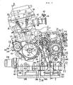
- the power unit P includes an in-series 4-cylinder internal combustion engine E supported by the down frames 18 and by the pivot plates 19 and a power transmission device T which changes and reduces the speed of the power of the engine E and transmits it to a rear wheel WR.
- the pivot plate 19 swingably supports the front end portion of a swing arm 25 via a support shaft 26 and the swing arm 25 has a rear end portion which rotatably supports a rear wheel WR.
- a rear cushion 27 is provided between each of the seat rails 20 and a corresponding one of the swing arms 25.
- Chain transmission means 33 is provided between an output shaft 28 of the power unit P and an axle 29 of the rear wheel WR.
- the chain transmission means 33 includes a drive sprocket 30 provided on the output shaft 28, a driven sprocket 31 secured to the axle 29, and an endless chain 32 wound around the drive sprocket 30 and around the driven sprocket 31.
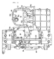
- the internal combustion engine E includes a crankcase 36; a cylinder block 37 joined to the upper portion of the crankcase 36; a cylinder head 38 joined to the upper end of the cylinder block 37; a head cover 38 joined to the cylinder head 38; and an oil pan 40 joined to the lower portion of the crankcase 36.
- Intake pipes 41 are each joined to the rear lateral surface of the cylinder head 38 so as to be associated with a corresponding one of cylinders.
- the intake pipe 41 is joint at an upstream end to a throttle body 43 attached with a fuel injection valve 42.
- the throttle body 43 is joined at an upstream end to an air cleaner 44 (see Fig. 1 ) located on the left side of the body frame F and above the rear portion of the power unit P.
- Exhaust pipes 45 are each joined to the front lateral surface of the cylinder head 38 so as to be associated with a corresponding one of the cylinders. As shown in Fig. 1 , the exhaust pipe 45 passes below the right side of the power unit P, extending rearward, and is joined to an exhaust muffler 46 disposed on the right side of the rear wheel WR.
- the crankcase 36 includes an upper case half body 48 and a lower case half body 49 which are coupled to each other at a split face 47 slanting forwardly upwardly.
- a crankshaft 50 having an axis CL1 extending in the width-direction of the motorcycle is rotatably carried between the upper case half body 48 and the lower case half body 49.
- the cylinder block 37 is joined to the upper case half body 48 of the crankcase 36 so as to slant forwardly upwardly toward the front of the traveling direction of the motorcycle.
- the cylinder block 37 is provided with four cylinder bores 51 lined in the direction of the axial line CL1 of the crankshaft 50.
- a piston 52 slidably fitted into each of the cylinder bores 51 is connected via a connecting rod 53 to a crank pin 50a provided for the crankshaft 50.
- the crankcase 36 is provided with six, first through sixth, journal walls 54 to 59 spaced apart from each other in the direction of the axial line CL1 of the crankshaft 50 from the left side to the right side in the state of being mounted on the motorcycle.
- the crankshaft 50 is rotatably journaled by the first through sixth journal walls 54 to 59.
- a rotor 60 is secured to an end of the crankshaft 50 outwardly projecting from the left lateral wall, i.e., the first journal wall 54 of the crankcase 36.
- a stator 61 constituting a generator 62 along with the rotor 60 is attached to a generator cover 63 fastened to the left lateral wall of the crankcase 36 so as to cover the generator 62.
- a starter motor 64 disposed within the generator cover 63 is mounted above the split face 47 to the crankcase 36 so as to have a rotational axis parallel to the crankshaft 50.
- a one-way clutch 67 is interposed between a gear 66 receiving power transmitted from the starter motor 64 via a reduction gear mechanism 65 and the rotor 60 of the generator 62 so as to enable power transmission from the side of the gear 66.
- a pulser 68 is secured to an end of the crankshaft 50 projecting from the right lateral wall, i.e., the sixth journal wall 59 of the crankcase 36.
- a rotation number sensor 70 is attached inside a pulser cover 69 so as to face the outer circumference of the pulser 68.
- the pulser cover 69 is joined to the crankcase 36 to cover the pulser 68.
- the third and fourth journal walls 56, 57 are disposed close to each other without putting the cylinder bore 51 therebetween.
- a chain chamber 73 is formed in the cylinder block 37 and in the cylinder head 38 at a portion corresponding to between the third and fourth journal walls 56, 57.
- the cylinder head 38 is provided with a pair of intake valves 74 for each cylinder and with a pair of exhaust valves 75 for each cylinder.
- the intake valves 74 and the exhaust valves 75 are provided in an openable and closable manner while being biased by springs in the valve-closing direction.
- a valve operating chamber 76 is formed between the cylinder head 38 and the head cover 39.
- a valve operating system 79 is received in the valve operating chamber 76 to drivingly open and close the intake valves 74 and the exhaust valves 75.
- the valve operating system 79 includes an intake side cam shaft 77 disposed parallel to the crankshaft 50 to be associated with the intake valves 74; and an exhaust side cam shaft 78 disposed parallel to the crankshaft 50 to be associated with the exhaust valves 75.
- the timing transmission means 80 includes a drive sprocket 81, driven sprockets 82, 83 and an endless timing chain 84.
- the drive sprocket 81 is provided on the crankshaft 50 between the third and fourth journal walls 56, 57.
- the driven sprockets 82 and 83 are provided on the intake side cam shaft 77 and on the exhaust side cam shaft 78, respectively, at respective positions corresponding to the drive sprocket 81.
- the timing chain 84 is wound around the drive sprocket 81 and around the driven sprockets 82, 83 so as to be able to run in the chain chamber 73.
- the crankcase 36 includes a front half portion 36a and a rear half portion 36b.
- the front half portion 36a is provided with the first through sixth journal walls 54 to 59.
- the rear half portion 36b has a right end portion flush with a right end portion of the front half portion 36a and a left end portion located inward of a left end portion of the front half portion 36a.
- the rear half portion 36b has a width narrower than that of the front half portion 36a in the direction of the axial line CL1 of the crankshaft 50.
- a left cover member 85 is joined to the rear half portion 36b from the left side and a first right cover member 86 is joined to the rear half portion 36b from the right side.
- a second right cover member 87 is joined to the first right cover member 86 from the right side.
- a third right cover member 88 is joined to the front half portion 36a and rear half portion 36b of the crankcase 36 so as to cover the second right cover member 87 from the right outside.
- the crankcase 36 is internally formed with a crank chamber 89 which receives therein the most portion of the crankshaft 50 and communicates with the cylinder bores 51.
- the crankcase 36 and the left cover member 85, the first right cover member 86 and the second right cover member 87 each of which is joined to the crankcase 36 define a continuously variable transmission chamber 90.
- the crankcase 36 is formed with a partition wall portion 36c which is disposed at a connection portion between the front half portion 36a and the rear half portion 36b to separate between the crank chamber 89 and the continuously variable transmission chamber 90.
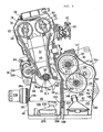
- the power transmission device T including the continuously variable transmission 91 is housed in the continuously variable transmission chamber 90.
- the power transmission device T includes the belt type continuously variable transmission 91 which enables continuously variable speed by hydraulic control; and an input clutch 92 interposed between the crankshaft 50 and the continuously variable transmission 91.
- the power transmission device T further includes the output shaft 28 which outwardly projects from the left cover member 85 to transmit power to the rear wheel WR; and a start clutch 93 and a gear transmission mechanism 94 interposed between the continuously variable transmission 91 and the output shat 28.
- the continuously variable transmission 91 includes a drive pulley shaft 95 parallel to the crankshaft 50; a driven pulley shaft 96 disposed above the drive pulley shaft 95; a drive pulley 97 provided on the drive pulley shaft 95; a driven pulley 98 provided on the driven pulley shaft 96; and an endless metal belt 99 wound around the drive pulley 97 and around the driven pulley 98.
- the continuously variable transmission 91 is disposed rearward of the axial line CL1 of the crankshaft 50.
- the axial line CL1 of the crankshaft 50, the axial line CL2 of the drive pulley 97, i.e., the axis of the drive pulley shaft 95 and the axial line CL3 of the driven pulley 98, i.e., the axis of the driven pulley shaft 96 are each located at a corresponding one of the apexes of an imaginary triangle VT1 on a view projected on a plane perpendicular to the axial line CL1 of the crankshaft 50 as clearly shown in Fig. 5 .
- the axial line CL1 of the crankshaft 50 and the axial line CL3 of the driven pulley 98 are located on the split face 47 of the crankcase 36.
- the driven pulley 98 is a downside-located pulley of the drive pulley 97 and driven pulley 98 located one above the other.
- the partition wall 36c provided in the crankcase 36 to separate between the crank chamber 89 and the continuously variable transmission chamber 90 is formed to slant toward the crankshaft 50 at a portion above the split face 47.
- the upside-located drive pulley 97 of the drive pulley 97 and driven pulley 98 is located at a position offset toward the crankshaft 50 with respect to a first vertical line VL1 passing the axial line CL3 of the downside-located driven pulley 98.
- the drive pulley shaft 95 rotatably passes through the rear half portion 36b of the crankcase 36, the first right cover member 86 and the second right cover member 87.
- the driven pulley shaft 96 rotatably passes through the rear half portion 36b of the crankcase 36 and the first right cover member 86.
- the external wall of the continuously variable transmission chamber 90 is composed of the rear half portion 36b of the crankcase 36, the left cover member 85, the first right cover member 86 and the second right cover member 87.
- a first oil pump 100 is disposed at the left cover member 85 which is a wall portion on one end side of the drive pulley shaft 95 so as to be coupled to one end of the drive pulley shaft 95.
- the first oil pump 100 is a trochoid pump.
- a pump case 101 for the first oil pump 100 includes the left cover member 85; a flat plate-like first case member 102 abutted against the inner surface of the left cover member 85; and a bowl-like second case member 103.
- a first pump chamber 104 is defined between the first case member 102 and the second case member 103.
- the first case member 102 is gripped between the left cover member 85 and the second case member 103.
- the first and second case members 102, 103 are co-fastened to the left cover member 85 with a plurality of bolts 105.
- One end portion of the drive pulley shaft 95 rotatably passes through the second case member 103 of the pump case 101 and projects into the first pump chamber 104.
- One end of the drive pulley shaft 95 is coupled to an inner rotor 106, of the inner rotor 106 and an outer rotor 107, incapably of relative rotation.
- the inner rotor 106 and the outer rotor 107 mesh with each other and are housed in the first pump chamber 104.
- a roller bearing 108 is interposed between the second case member 103 and the drive pulley shaft 95.
- a water pump 109 coaxial with the first oil pump 100 is disposed on the external surface side of the left cover member 85 at a portion corresponding to the first oil pump 100.
- a pump case 110 of the water pump 109 includes a third case member 111 and a fourth case member 112.
- the third case member 85 has a tubular support cylindrical portion 111 a which is formed integrally therewith, extends coaxially with the drive pulley shaft 95 and is partially fitted into the left cover member 85 in a liquid-tight manner.
- the fourth case member 112 is joined to the third case member 111 to define a second pump member 113 therebetween.
- the third and fourth case members 111, 112 are co-fastened and joined to the left cover member 85 with a plurality of bolts 114.
- An impeller 115 housed in the second pump chamber 113 is secured to one end of a pump shaft 116.
- the pump shaft 116 is liquid-tightly and rotatably inserted into a support cylindrical portion 111 a.
- One end of the pulley shaft 95 is coaxially coupled to the other end of the pump shaft 116 incapably of relative rotation.
- the other end of the drive pulley shaft 95 is fitted into the third right cover member 88 via an annular sealing member 117.
- a ball bearing 118 is interposed between the drive pulley shaft 95 and the second right cover member 87.
- driven pulley shaft 96 is rotatably journaled by the left cover member 85 via a roller bearing 119.
- the other end of the driven pulley shaft 96 rotatably passes through the first right cover member 86.
- a ball bearing 120 is interposed between the driven pulley shaft 96 and the first right cover member 86.
- Rotational power from the crankshaft 50 is transmitted to the drive pulley shaft 95 via a primary reduction gear mechanism 121 and via a damper spring 122.
- the primary reduction gear mechanism 121 reduces the speed of the rotational power from the crankshaft 50 and transmits it toward the drive pulley shaft 95.
- the primary reduction gear mechanism 121 includes a primary drive gear 123 provided on the crankshaft 50 and a primary driven gear 124 meshing with the primary drive gear 123.
- the primary drive gear 123 is integrally formed on the crankshaft 50 so as to be located between the fifth and sixth journal walls 58, 59.
- a transmitting member 125 having a cylindrical portion 125a coaxially surrounding the drive pulley shaft 95 is secured to the drive pulley shaft 95 between the second and third right cover members 87, 88.
- the primary driven gear 124 is carried on the transmitting member 125 so as to enable relative rotation within a limited range.
- the damper spring 122 is provided between the primary driven gear 124 and the transmitting member 125.
- An annular sealing member 126 is interposed between the cylindrical portion 125a of the transmitting member 125 and the second right cover member 87.
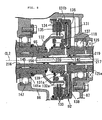
- the input clutch 92 is attached to the drive pulley shaft 95 between the first and second right cover members 86, 87 in the continuously variable transmission chamber 90.
- the input clutch 92 includes a clutch outer 131; a clutch inner 132; a plurality of first drive friction plates 133; a plurality of first driven friction plates 134; a pressure-receiving plate 135; a pressurizing plate 136; and a clutch spring 137.
- the clutch outer 131 has a tubular inner cylindrical portion 131 a joined to the drive pulley shaft 95 incapably of relative rotation and an outer cylindrical portion 131 b coaxially surrounding the inner cylindrical portion 131a.
- the clutch inner 132 has a cylindrical portion 132a coaxially disposed between the inner cylindrical portion 131 a and outer cylindrical portion 131 b of the clutch outer 131.
- the first drive friction plates 133 are axially slidably spline-fitted to the outer cylindrical portion 131 b of the clutch outer 131.
- the first driven friction plates 134 are alternately superimposed on the first drive friction plates 133 and axially slidably spline-fitted to the cylindrical portion 132a of the clutch inner 132.
- the pressure-receiving plate 135 is secured to the outer cylindrical portion 131 b of the clutch outer 131 so as to face, from one axial direction, the first drive friction plates 133 and first driven friction plates 134 that are superimposed on each other.
- the pressurizing plate 136 faces, from the other axial direction, the first drive friction plates 133 and first driven friction plates 134 that are superimposed on each other.
- the clutch spring 137 biases the pressurizing plate 136 toward the side where the pressurizing plate 136 is spaced from the pressure-receiving plate 135.
- the pressurizing plate 136 is adapted to define a first hydraulic chamber 138 between the clutch outer 131 and the pressurizing plate 136.
- the pressurizing plate 136 is slidably supported by the inner cylindrical portion 131 a and outer cylindrical portion 131 b of the clutch outer 131.
- the clutch spring 137 is compressively provided between the pressurizing plate 136 and a spring-receiving member 139 attached to the inner cylindrical portion 131 a of the clutch outer 131.
- the drive pulley shaft 95 is provided with a first oil hole 140 communicating with the first hydraulic chamber 138.
- the hydraulic pressure of the first hydraulic chamber 138 is increased to move the pressurizing plate 136 forward, i.e., toward the pressure-receiving plate 135 against the spring force of the clutch spring 137.
- the first drive friction plates 133 and first driven friction plates 134 are pressurized and gripped between the pressurizing plate 136 and the pressure-receiving plate 135.
- a clutch-off state is brought according to the reduced hydraulic pressure of the first hydraulic chamber 138.
- the drive pulley 97 includes a drive side stationary pulley half body 141 and a drive side movable pulley half body 142.
- the stationary pulley half body 141 has a tubular cylinder-shaft portion 141 a integrally formed therewith to coaxially surround the drive pulley shaft 95 and is carried on the drive pulley shaft 95 for relative rotation.
- the movable pulley half body 142 is carried on the cylinder-shaft portion 141 a incapably of relative rotation but capably of axial slide and is opposed to the drive side stationary pulley half body 141.
- the cylinder-shaft portion 141 a rotatably passes through the first right cover member 86 and is coupled to the clutch inner 132 of the input shaft 92 coaxially and incapably of relative rotation.
- the cylinder-shaft portion 141 a i.e., the drive side stationary pulley half body 141 is rotated together with the drive pulley shaft 95 in the clutch-on state of the input clutch 92.
- a ball bearing 147 is interposed between the cylinder-shaft portion 141 a and the first right cover member 86.
- the drive side movable pulley half body 142 is disposed at a position opposed to the drive side stationary pulley half body 141 from the side opposite to the first right cover member 86.
- the drive side movable pulley half body 142 has a cylindrical first boss portion 142a that is formed integrally therewith to coaxially surround the cylinder-shaft portion 141 a and to be coupled to the cylinder-shaft portion 141 a incapably of relative rotation but capably of axial slide.
- a drive side hydraulic drive mechanism 148 for slidably driving the drive side movable pulley half body 142 is disposed on the cylinder-shaft portion 141 a on the side opposed to the drive side stationary pulley half body 141 with respect to the drive side movable pulley half body 142.
- the drive side hydraulic drive mechanism 148 includes a cylindrical case portion 142b; a ring plate-like first end plate 150; a stationary bawl-like body 151; and a second end plate 152.
- the case portion 142b is integrally formed on the outer circumferential portion of the drive side movable pulley half body 142 so as to coaxially surround the first boss portion 142a and to extend oppositely to the drive side stationary pulley half body 141.
- the first end plate 150 is in slidable contact with the inner circumference of the case portion 142b and with the outer circumference of the first boss portion 142a in a liquid-tight manner to define a second hydraulic pressure chamber 149 between the drive side movable pulley half body 142 and the first end plate 150.
- the drive side movable pulley half body 142 is biased by the hydraulic force according to the hydraulic pressure applied to the second and third hydraulic chambers 149, 153 to move the drive side movable pulley half body 142 close to the drive side stationary pulley half body 141 to increase the winding radius of the belt 99 wound around the drive pulley 97.
- the driven side movable pulley half body 144 is disposed at a position corresponding to the drive side stationary pulley half body 141 of the drive pulley 97.
- the driven side movable pulley half body 144 is integrally provided in an internal circumferential portion with a second boss portion 144a.
- the second boss portion 144a extends toward the side opposite to the driven side stationary pulley half body 143 and coaxially surrounds the driven pulley shaft 96.
- the second boss portion 144a is coupled to the driven pulley shaft 96 incapably of relative rotation but capably of axial movement.
- the drive side stationary pulley half body 141 and the driven side movable pulley half body 144 are disposed to partially overlap each other as viewed from the respective directions of the respective axial lines CL2, CL3 of the drive pulley shaft 95 and the driven pulley shaft 96.
- a relief recess portion 159 is provided on the outer circumference of the driven side movable pulley half body 144.
- a driven side hydraulic drive mechanism 160 for slidably driving the driven side movable pulley half body 144 is disposed on the driven pulley shaft 96 on the side opposite to the driven side stationary pulley half body 143 with respect to driven side movable pulley half body 144.
- the driven side hydraulic drive mechanism 160 includes a tubular case member 161; an end wall member 163; and a coil spring 164.
- the case member 161 coaxially surrounds the second boss portion 144a, is secured at one end to the outer circumferential portion of the driven side movable pulley half body 144 and extends toward the side opposite to the driven side stationary pulley half body 143.
- the driven pulley shaft 96 is provided with a fourth oil hole 165 communicating with the fourth hydraulic chamber 162.
- the driven side movable pulley half body 144 is biased by the hydraulic force according to the hydraulic pressure applied to the fourth hydraulic chamber 162 to move the driven side movable pulley half body 144 close to the driven side stationary pulley half body 143 to increase the winding radius of the belt 99 wound around the driven pulley 98.
- a restrictive plate portion 161 a is integrally provided at the other end of the case member 161 to protrude radially inwardly.
- the restrictive plate portion 161 a is abutted against the end wall member 163 from the side opposite to the driven side stationary pulley half body 143 to restrict the movement of the driven side movable pulley half body 144 close to the driven side stationary pulley half body 143.
- the start clutch 93 is mounted to the driven pulley shaft 96 between the driven pulley 98 of the continuously variable transmission 91 and the left cover member 85.
- the start clutch 93 includes a clutch outer 169; a clutch inner 170; a plurality of second drive friction plates 172; a plurality of second driven friction plates 173; a pressure-receiving plate 174; a piston 175; and a spring 177.
- a tubular boss member 168 is joined to the inner circumference of the clutch outer 169 and to the driven pulley shaft 96 incapably of relative rotation.
- the clutch inner 170 is coaxially surrounded by the clutch outer 169 and carried on the driven pulley shaft 96 via a needle bearing 171 for relative rotation.
- the second drive friction plates 172 are engaged with the clutch outer 169 incapably of relative rotation.
- the second driven friction plates 173 are engaged with the clutch inner 170 incapably of relative rotation and alternately superposed on the second drive friction plates 172.
- the pressure-receiving plate 174 is fixedly supported by the clutch outer 169 so as to face the second drive and driven friction plates 172, 173 alternately superposed on each other.
- the piston 175 grips the second drive and driven friction plates 172, 173 between the pressure-receiving plate 174 and the piston 175 and defines a fifth hydraulic chamber 176 between the clutch outer 169 and the piston 175.
- the spring 177 biases the piston 175 in a direction to reduce the volume of the fifth hydraulic chamber 176.
- the inner circumferential portion of the piston 175 is in slidable contact with the outer circumferential portion of the boss member 168 in a liquid-tight manner.
- the outer circumferential portion of the piston 175 is in slidable contact with the clutch outer 169 in a liquid-tight manner.
- the driven pulley shaft 96 is provided with a fifth oil hole 178 communicating with the fifth hydraulic chamber 176. According to an increase in the hydraulic pressure of the fifth hydraulic chamber 176, the piston 175 is operated to grip and pressurize the second drive and driven friction plates 172, 173 between the pressure-receiving plate 174 and the piston 175.
- the start clutch 93 is brought into a clutch-on state where the rotational power transmitted from the driven pulley shaft 96 to the clutch outer 169 is transmitted to the clutch inner 170.
- a wall member 180 is secured at an inner circumferential portion to the boss member 168 to define a canceller chamber 179 between the piston 175 and the wall member 180 and on the side opposite to the fifth hydraulic chamber 176.
- the piston 175 is in slidable contact with the outer circumferential portion of the wall member 180 in a liquid-tight manner.
- the spring 177 is housed in the canceller chamber 179 and interposed between the piston 175 and the wall member 180.
- the driven pulley shaft 96 and the boss member 169 are provided with a branch oil passage 181 adapted to lead lubricating oil to the canceller chamber 179.
- one end of the output shaft 28 rotatably passes through the left cover member 85.
- An annular sealing member 182 and a ball bearing 183 are interposed between the output shaft 28 and the left cover member 85 in the order from the external side.
- the drive sprocket 30 constituting part of the chain transmission means 33 is secured to one end of the output shaft 28 extending from the left cover member 85.
- the other end of the output shaft 28 is rotatably journaled by the rear half portion 36b of the crankcase 36 via a roller bearing 184.
- the drive pulley shaft 95 passes through the second right cover 87 interposed between the crank chamber 89 and the continuously variable transmission chamber 90, of the rear half portion 36b of the crankcase 36, the left cover member 85, the first right cover member 86 and the second right cover member 87 constituting the outer wall of the continuously variable transmission chamber 90.
- the annular sealing member 126 is interposed between the second right cover member 87 and the transmitting member 125 fixedly brought into close contact with the outer circumference of the drive pulley shaft 95.
- the annular sealing member 117 is interposed between the other end of the tubular drive pulley shaft 95 and the third right cover member 88. In this way, the continuously variable transmission chamber 90 is liquid-tightly isolated from the crank chamber 89.
- an endlessly continuous first split face 190 is formed on the lower surface of the front half portion 36a in the lower case half body 49 of the crankcase 36 so as to correspond to the crank chamber 39.
- a second split face 191 is formed on the lower surface of the rear half portion 36b in the lower case half body 49 of the crankcase 36 and on the lower surface of the left cover member 85 joined to the rear half body 36b so as to correspond to the continuously variable transmission chamber 90 while endlessly continuing into and sharing part of the first split face 190 at the partition wall portion 36c.
- the oil pan 40 is fastened to the crankcase 36 and to the left cover member 85 with a plurality of bolts 198 in such a manner that the third and fourth split faces 194, 195 are joined to the first and second split faces 190, 191.
- the internal combustion engine side oil storage chamber 196 is allowed to communicate with the lower portion of the crank chamber 89.
- a ceiling wall portion 199 is provided on the rear half portion 36b of the lower case half body 49 in the crankcase 36 and on the left cover member 85 so as to be interposed between the continuously variable transmission side oil storage chamber 197 and the continuously variable transmission chamber 90 and to serve as a ceiling wall of the continuously variable transmission side oil storage chamber 197.
- the ceiling wall portion 199 is provided with a plurality of communication holes 200 adaptable for communication between the continuously variable transmission side oil storage chamber 197 and the continuously variable transmission chamber 90. This allows the continuously variable transmission side oil storage chamber 197 to communicate with the continuously variable transmission chamber 90.
- the continuously variable transmission side oil storage chamber 197 is disposed to be offset leftward from the body centerline C1 in such a manner that its center C2 with respect to the width-direction of the motorcycle is offset leftward or rightward from the body centerline C1 on the center of the width-direction.
- the center C2 is disposed to be offset leftward from the body centerline C1.
- the continuously variable transmission side oil storage chamber 197 is formed to partially protrude outwardly from the continuously variable transmission chamber 90 on the side where the continuously variable transmission side oil storage chamber 197 is offset from the body centerline C1.
- the continuously variable transmission 91 is disposed to be offset rightward from the body centerline C1 conversely to the continuously variable transmission side oil storage chamber 197.
- the center C2 of the continuously variable transmission side oil storage chamber 197 with respect to the width-direction of the motorcycle is disposed to be offset leftward from the body centerline C1.
- the continuously variable transmission side oil storage chamber 197 protrudes outwardly from the continuously variable transmission chamber 90.
- an empty space can be ensured on the right side from the body centerline C1 and below the crankcase 36.
- the four exhaust pipes 45, a collecting exhaust pipe 210 collecting the exhaust pipes 45 and the like are arranged in the space.
- the body frame F or internal combustion engine E is provided with respective steps 211, 211 on both sides of the motorcycle.
- the bank angle ⁇ of the motorcycle is determined by both the steps 211, 211.
- the continuously variable transmission side oil storage chamber 197 is formed to partially protrude outwardly (in this embodiment, leftwardly) from the continuously variable transmission chamber 90 in a range where the oil storage chamber 197 is accommodated in the bank angle ⁇ .
- a gauge hole 204 (see Fig. 11 ) is provided at a portion, outwardly protruding from the continuously variable transmission chamber 90, of the ceiling wall portion 199 which is a ceiling wall of the continuously variable transmission side oil storage chamber 197.
- the gauge hole 204 has an axis that slant to be spaced from the outer surface of the left cover member 85 as it goes upward.
- a level gauge 205 (see Figs. 2 and 7 ) is removably attached to the gauge hole 204 in order to check the amount of the oil stored in the continuously variable transmission side oil storage chamber 197.
- the hydraulic pressure controlled by the hydraulic control device 215 is supplied to the first hydraulic chamber 138 of the input shaft 92, to the second and third hydraulic chambers 149, 153 of the drive side hydraulic drive mechanism 148, and to the fourth hydraulic chamber 162 of the driven side hydraulic drive mechanism 160 and the fifth hydraulic chamber 176 of the start clutch 93.
- the drive pulley shaft 95 is coaxially provided with a first central oil passage 216 bottomed and opening toward the third right cover member 88.
- a cylindrical first tubular member 217 is liquid-tightly and coaxially inserted into the first central oil passage 216 so as to communicate with the third central oil passage 216.
- An oil passage 218 communicating with the first tubular member 217 is provided in the third right cover member 88 so as to lead hydraulic pressure from the hydraulic control device 215 thereto.
- a cylindrical second tubular member 219 is coaxially inserted into the first central oil passage 216 so as to coaxially surround the first tubular member 217.
- the second tubular member 219 is adapted to define, between the first and second tubular members 217, 218, an annular passage 220 (see Fig. 8 ) communicating with the first oil passage 140 continuous to the first hydraulic chamber 138 of the input clutch 92.
- An electromagnetic valve 221 (see Figs. 3 and 7 ) is mounted to the third right cover member 88 to switch the application and release of the hydraulic pressure discharged from the first oil pump 100 to the annular passage 220.
- an oil trainer 232 is installed in the internal combustion engine side oil storage chamber 196 of the oil pan 40.
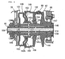
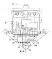
- a second oil pump 234 for pumping oil from the internal combustion engine side oil storage chamber 196 via the oil strainer 232 is mounted on the lower case half body 49 of the crankcase 36 so as be disposed between the second and third journal walls 55, 56 as shown in Fig. 15 .
- the oil discharged from the second oil pump 234 is supplied to the lubricating portions of the internal combustion engine E.
- a balancer 241 a secondary balancer, is disposed between fourth and fifth journal walls 57, 58.
- This balancer 241 is rotatably supported by a balancer shaft 242 carried by the fourth and fifth journal walls 57, 58 of the lower case half body 49 of the crankcase 36.
- the fourth journal wall 57 of the lower case half body 49 is provided with a support hole 243 adapted to receive and support one end of the balancer shaft 242 inserted thereinto.
- the fifth journal wall 58 is provided with a support hole 244 adapted to receive the other end of the balancer shaft 242 passed therethrough.
- the end portion of the balancer shaft 242 projecting from the fifth journal wall 58 is gripped by a gripping member 245, which is fastened to the fifth journal wall 58 of the lower case half body 49 with a bolt 246.
- the balancer 241 is formed to coaxially surround the balancer shaft 242 between the fourth and fifth journal walls 57, 58.
- a pair of needle bearings 247, 247 is interposed between the balancer shaft 242 and the balancer 241 so as to be axially spaced apart from each other.
- a driven gear 249 is coaxially interlocked with and connected to the end of the balancer 241 close to the fifth journal wall 58.
- the driven gear 249 coaxially surrounds the balancer 241 so as to engage it via a plurality of elastic members 248.
- the drive pulley 97 and driven pulley 98 of the continuously variable transmission 91 in the power transmission device T are arranged one above the other such that the drive pulley 97 is located above the driven pulley 98.
- the respective positions of the drive pulley 97 and the driven pulley 98 are set so that a first straight line L1 is parallel to a second straight line L2.
- the first straight line L1 connects the axial line CL2 of the drive pulley 97 with the axial line CL3 of the driven pulley 98.
- the second straight line L2 connects the axial line CL1 of the crankshaft 50 with an axial line disposed rearward of the second vertical line VL2 passing the axial line CL1 of the crankshaft 50, i.e., with the axial line CL4 of the pump shaft 240, of the axial line CL4 of the pump shaft 240 and the axial line CL5 of the balancer 241.
- the partition wall 36c provided in the crankcase 36 is formed to slant toward the crankshaft 50 at a portion above the split face 47.
- the downward-located drive pulley 97 of the drive pulley 97 and the driven pulley 98 is disposed at a position offset toward the crankshaft 50 from the first vertical line VL1 passing the axial line CL3 of the downward-located driven pulley 98.
- the distance between the crankshaft 50 and the drive pulley 97 can be reduced to make the power unit P compact in the back and forth direction.
- the driven sprocket 236 provided on the pump shaft 240 of the second oil pump 234 and the driven gear 249 coaxially interlocked with and connected to the balancer 241 are offset from each other in the vehicle-width direction and are located at a position where they at least partially overlap each other as viewed from the side of the vehicle-width direction.
- the second oil pump 236 and the balancer 241 are arranged in the crankcase 36 so as to reduce the misalignment therebetween in the back and forth direction, thereby downsizing the power unit P in the back and forth direction.
- the axial line CL4 of the pump shaft 240, the axial line CL5 of the balancer 241, and the axial line CL1 of the crankshaft 50 are each disposed at a corresponding one of the apexes of the imaginary triangle VT2 with the axial line CL1 of the crankshaft 50 located at an upper apex thereof in a view projected on a plane perpendicular to the axial line CL1 of the crankshaft 50.
- the axial line CL4 of the pump shaft 240 and the axial line CL5 of the balancer 241 are arranged in front or rear of the vertical line VL2 passing the axial line CL1 of the crankshaft 50.
- the oil pan 40 joined to the crankcase 36 is internally partitioned into the internal combustion engine side oil storage chamber 196 and the continuously variable transmission side oil storage chamber 197.
- the continuously variable transmission chamber 90 liquid-tightly isolated from the crank chamber 89 is allowed to communicate with the continuously variable transmission side oil storage chamber 197.
- the partition wall 193 provided in the oil pan 40 can increase the rigidity of the oil pan 40 which tends to increase in size to ensure the amount of oil for the internal combustion engine E and for the continuously variable transmission 91.
- the continuously variable transmission side oil storage chamber 197 is formed to partially protrude outwardly from the continuously variable transmission chamber 90 in the width-direction of the motorcycle. If the oil pan 40 is downwardly enlarged to sufficiently ensure the amount of oil, an influence is exerted on the minimum ground clearance of the motorcycle. However, it is possible to prevent the lowering of the minimum ground clearance while sufficiently ensuring the capacity of the oil pan 40. Thus, it is possible to efficiently arrange the oil pan 40 in the limited space of the motorcycle.
- the continuously variable transmission side oil storage chamber 197 is formed to protrude outwardly from the continuously variable transmission chamber 90 in the range of the bank angle ⁇ determined by the steps 211 disposed on both the sides of the motorcycle. Thus, the partially protruding formation of the continuously variable transmission side oil storage chamber 197 has no influence on the bank angle ⁇ .
- the center C2 of the continuously variable transmission side oil storage chamber 197 with respect to the width-direction is disposed to be offset to one side from the body centerline C1.
- the continuously variable transmission 91 is disposed at a position offset to the other side from the body centerline C1.
- the pump driven member 236 and the balancer driven member 249 are offset from each other in a vehicle-width direction and are located at such a position as to at least partially overlap each other as viewed from the side of the vehicle-width direction.
Claims (2)
- Antriebseinheit für ein Kraftrad, umfassend:einen Verbrennungsmotor (E), welcher mit einem Kurbelgehäuse (36) versehen ist, welches drehbar eine Kurbelwelle (50) mit einer sich in einer Fahrzeugbreitenrichtung erstreckenden Achslinie (CL1) lagert; undeine Kraftübertragungseinrichtung (T), um die Geschwindigkeit einer Rotationskraft der Kurbelwelle (50) zu ändern und zu reduzieren und die resultierende Rotationskraft zu einem Hinterrad zu übertragen;wobei eine Ölpumpe (234), um Schmierabschnitten des Verbrennungsmotors (E) Öl zuzuführen, an dem Kurbelgehäuse (36) angebracht ist und eine Ausgleichseinrichtung (241) drehbar durch das Kurbelgehäuse (36) gelagert ist;wobei eine Rotationskraft von der Kurbelwelle (50) zu einem auf einer Pumpenwelle (240) von der Ölpumpe (234) vorgesehenen Pumpenabtriebselement (236) und zu einemAusgleichseinrichtungsabtriebselement (249) übertragen wird, welches koaxial mit der Ausgleichseinrichtung (241) gekoppelt und verbunden ist,um Kraft zu der Ausgleichseinrichtung (241) zu übertragen;wobei das Pumpenabtriebselement (236) und das Ausgleichseinrichtungsabtriebselement (249) voneinander in einer Fahrzeugbreitenrichtung versetzt sind und an einer derartigen Position angeordnet sind, dass sie einander, von der Seite der Fahrzeugbreitenrichtung her gesehen, wenigstens teilweise überlappen;wobei eine Achslinie (CL4) der Pumpenwelle (240), eine Achslinie (CL5) der Ausgleichseinrichtung (241), und die Achslinie (CL1) der Kurbelwelle (50) jeweils an einem jeweiligen von Scheitelpunkten eines imaginären Dreiecks (VT2) angeordnet sind, wobei die Achslinie (CL1) der Kurbelwelle (50) in einer auf eine Ebene orthogonal zu der Achslinie (CL1) der Kurbelwelle (50) projizierten Ansicht an einem oberen Scheitelpunkt davon angeordnet ist;dadurch gekennzeichnet,dass die Kraftübertragungseinrichtung (T) rückwärts von der Kurbelwelle (50) angeordnet ist, die Kraftübertragungseinrichtung ( T) ein stufenlos verstellbares Getriebe (91) umfasst mit einem Riemen (99), welcher um eine Antriebsriemenscheibe (97), welche eine von der Kurbelwelle (50) zu dieser übertragene Kraft aufnimmt, und um eine Abtriebsriemenscheibe (98) gewickelt ist; und dass die Antriebsriemenscheibe (97) und die Abtriebsriemenscheibe (98) übereinander angeordnet sind, so dass in der auf die Ebene projizierten Ansicht eine erste gerade Linie (L1) parallel zu einer zweiten geraden Linie (L2) ist, wobei die erste gerade Linie (L1) die jeweiligen Achslinien (CL2, CL3) der Antriebsriemenscheibe (97) und der Abtriebsriemenscheibe (98) verbindet, die zweite gerade Linie (L2) die Achslinie (CL1) der Kurbelwelle (50) mit einer Achslinie, welche rückwärts von der vertikalen Linie (VL2) angeordnet ist, welche die Achslinie der Kurbelwelle (50) passiert, von der Achslinie (CL4) der Pumpenwelle (240) und der Achslinie (CL5) der Ausgleichseinrichtung (241) verbindet.
- Antriebseinheit für ein Kraftrad nach Anspruch 1, wobei die Achslinie (CL4) der Pumpenwelle (240) und die Achslinie (CL5) der Ausgleichseinrichtung (241) vor oder hinter einer vertikalen Linie (VL2) angeordnet sind, welche die Achslinie (CL1) der Kurbelwelle (50) passiert.
Applications Claiming Priority (1)
| Application Number | Priority Date | Filing Date | Title |
|---|---|---|---|
| JP2007165156A JP4914776B2 (ja) | 2007-06-22 | 2007-06-22 | 自動二輪車用パワーユニット |
Publications (2)
| Publication Number | Publication Date |
|---|---|
| EP2006200A1 EP2006200A1 (de) | 2008-12-24 |
| EP2006200B1 true EP2006200B1 (de) | 2010-09-15 |
Family
ID=39608179
Family Applications (1)
| Application Number | Title | Priority Date | Filing Date |
|---|---|---|---|
| EP08008785A Expired - Fee Related EP2006200B1 (de) | 2007-06-22 | 2008-05-09 | Antriebseinheit für ein Motorrad |
Country Status (6)
| Country | Link |
|---|---|
| US (1) | US8028669B2 (de) |
| EP (1) | EP2006200B1 (de) |
| JP (1) | JP4914776B2 (de) |
| CN (1) | CN101327829B (de) |
| CA (1) | CA2631470C (de) |
| DE (1) | DE602008002474D1 (de) |
Families Citing this family (12)
| Publication number | Priority date | Publication date | Assignee | Title |
|---|---|---|---|---|
| JP4939190B2 (ja) * | 2006-11-30 | 2012-05-23 | 本田技研工業株式会社 | 小型車両用パワーユニット |
| JP4451437B2 (ja) * | 2006-12-28 | 2010-04-14 | 本田技研工業株式会社 | 自動二輪車用パワーユニット |
| JP2008223880A (ja) * | 2007-03-13 | 2008-09-25 | Yamaha Motor Co Ltd | 内燃機関およびそれを備えた車両 |
| JP4751372B2 (ja) * | 2007-06-22 | 2011-08-17 | 本田技研工業株式会社 | 自動二輪車用パワーユニット |
| JP5174547B2 (ja) * | 2007-07-10 | 2013-04-03 | ヤマハ発動機株式会社 | 吸気システムおよびそれを備えた自動二輪車 |
| JP5339606B2 (ja) * | 2009-03-31 | 2013-11-13 | 本田技研工業株式会社 | ハイブリッド自動二輪車 |
| JP5572413B2 (ja) * | 2009-03-31 | 2014-08-13 | 本田技研工業株式会社 | ハイブリッド車両 |
| JP5474618B2 (ja) * | 2010-03-11 | 2014-04-16 | 本田技研工業株式会社 | 内燃機関のクラッチアクチュエータ取付構造 |
| JP2014065465A (ja) * | 2012-09-27 | 2014-04-17 | Honda Motor Co Ltd | 自動二輪車用内燃機関 |
| DE102015006365B4 (de) * | 2015-05-20 | 2021-09-30 | Deutz Aktiengesellschaft | Brennkraftmaschine mit mindestens einem Elektromotor |
| JP6215888B2 (ja) * | 2015-09-30 | 2017-10-18 | 本田技研工業株式会社 | ハイブリッド式パワーユニット |
| JP6756782B2 (ja) * | 2018-07-06 | 2020-09-16 | 本田技研工業株式会社 | 内燃機関 |
Family Cites Families (25)
| Publication number | Priority date | Publication date | Assignee | Title |
|---|---|---|---|---|
| JPS5675343A (en) * | 1979-11-16 | 1981-06-22 | Canon Inc | Mounting device for paper |
| JPS6394339A (ja) * | 1986-10-09 | 1988-04-25 | Nec Corp | 仮想計算機システム |
| JPH02223637A (ja) * | 1988-10-21 | 1990-09-06 | Yamaha Motor Co Ltd | エンジンのウォータポンプ配置構造 |
| JP2952515B2 (ja) * | 1990-08-30 | 1999-09-27 | ヤマハ発動機株式会社 | 自動二輪車用エンジンの潤滑ポンプ装置 |
| JP3470355B2 (ja) * | 1993-08-23 | 2003-11-25 | スズキ株式会社 | ドライサンプエンジンのオイル通路 |
| JPH1073014A (ja) * | 1996-08-29 | 1998-03-17 | Aisin Seiki Co Ltd | オイルパンの隔壁構造 |
| JP4083837B2 (ja) * | 1997-01-31 | 2008-04-30 | 本田技研工業株式会社 | 車両のエンジン支持装置 |
| JPH11294161A (ja) * | 1998-04-13 | 1999-10-26 | Yamaha Motor Co Ltd | 車両の水冷式エンジン冷却装置 |
| JP3823630B2 (ja) | 1999-08-30 | 2006-09-20 | スズキ株式会社 | 自動二輪車の変速装置 |
| JP3960450B2 (ja) * | 2000-02-22 | 2007-08-15 | 本田技研工業株式会社 | 内燃機関のバランサ組付構造 |
| JP4042947B2 (ja) * | 2000-10-13 | 2008-02-06 | 本田技研工業株式会社 | 動力装置の潤滑構造 |
| JP3984010B2 (ja) * | 2001-08-22 | 2007-09-26 | 本田技研工業株式会社 | エンジンのバランサー装置 |
| JP2003085285A (ja) | 2001-09-13 | 2003-03-20 | Matsushita Electric Ind Co Ltd | 認定審査会の事前審査支援システム構築装置及び認定審査会の事前審査支援システム構築用のプログラム並びにそのプログラムが記録されたコンピュータ読み取り可能な記録媒体 |
| JP2003120796A (ja) * | 2001-10-16 | 2003-04-23 | Toyota Motor Corp | 歯車装置の歯打ち音低減機構 |
| JP2003184566A (ja) * | 2001-12-20 | 2003-07-03 | Yamaha Motor Co Ltd | 単気筒エンジン |
| WO2003085285A1 (fr) | 2002-04-08 | 2003-10-16 | Yamaha Hatsudoki Kabushiki Kaisha | Moteur |
| JP4106962B2 (ja) * | 2002-05-17 | 2008-06-25 | スズキ株式会社 | 内燃機関におけるバランサシャフト周辺構造 |
| US7588009B2 (en) * | 2003-06-23 | 2009-09-15 | Honda Motor Co., Ltd. | Layout structure of a fuel injection device in a motor cycle |
| JP4270954B2 (ja) * | 2003-06-23 | 2009-06-03 | 本田技研工業株式会社 | 自動二輪車 |
| JP4163576B2 (ja) * | 2003-08-20 | 2008-10-08 | 本田技研工業株式会社 | エンジンの始動装置 |
| JP2007022098A (ja) * | 2003-10-23 | 2007-02-01 | Yamaha Motor Co Ltd | 鞍乗型車両用エンジン及びこれを備えた鞍乗型車両 |
| JP2005308001A (ja) * | 2004-04-16 | 2005-11-04 | Suzuki Motor Corp | エンジンのバランサ装置 |
| JP2006046326A (ja) * | 2004-07-09 | 2006-02-16 | Yamaha Motor Co Ltd | 1次バランサ付きエンジンおよび自動二輪車 |
| JP4580856B2 (ja) * | 2005-10-17 | 2010-11-17 | 本田技研工業株式会社 | スクータ型車両 |
| JP4545131B2 (ja) * | 2006-09-29 | 2010-09-15 | 本田技研工業株式会社 | 動力伝達装置 |
-
2007
- 2007-06-22 JP JP2007165156A patent/JP4914776B2/ja not_active Expired - Fee Related
-
2008
- 2008-05-09 DE DE602008002474T patent/DE602008002474D1/de active Active
- 2008-05-09 EP EP08008785A patent/EP2006200B1/de not_active Expired - Fee Related
- 2008-05-16 CA CA2631470A patent/CA2631470C/en not_active Expired - Fee Related
- 2008-06-19 US US12/142,457 patent/US8028669B2/en not_active Expired - Fee Related
- 2008-06-20 CN CN2008101288519A patent/CN101327829B/zh not_active Expired - Fee Related
Also Published As
| Publication number | Publication date |
|---|---|
| CA2631470C (en) | 2011-03-29 |
| JP2009002272A (ja) | 2009-01-08 |
| CN101327829A (zh) | 2008-12-24 |
| JP4914776B2 (ja) | 2012-04-11 |
| US8028669B2 (en) | 2011-10-04 |
| DE602008002474D1 (de) | 2010-10-28 |
| CN101327829B (zh) | 2011-10-12 |
| US20080314687A1 (en) | 2008-12-25 |
| CA2631470A1 (en) | 2008-12-22 |
| EP2006200A1 (de) | 2008-12-24 |
Similar Documents
| Publication | Publication Date | Title |
|---|---|---|
| EP2006200B1 (de) | Antriebseinheit für ein Motorrad | |
| US7951025B2 (en) | Power unit for motorcycle | |
| CA2631490C (en) | Power unit for motocycle | |
| US8002653B2 (en) | Power unit having engine and continuously variable transmission, configuration thereof, and vehicle incorporating same | |
| US7578277B2 (en) | Pump drive structure of water-cooled internal combustion engine | |
| JP4451437B2 (ja) | 自動二輪車用パワーユニット | |
| US7665561B2 (en) | Power unit for a motorcycle, and motorcycle incorporating same | |
| US8770160B2 (en) | Engine for small vehicle | |
| EP2239430B1 (de) | Ölaufbewahrungsstruktur für einen Motor | |
| US8147370B2 (en) | Power unit for motorcycle | |
| US8512181B2 (en) | Power unit for small vehicle | |
| EP2042766B1 (de) | Struktur zur Bereitstellung einer Kupplungssteuervorrichtung in einer Leistungseinheit für ein Motorrad | |
| JP2008138759A5 (de) | ||
| JP2007024007A (ja) | 内燃機関の潤滑装置 | |
| US7823667B2 (en) | Power unit for small vehicle | |
| JP2010196638A (ja) | パワーユニット | |
| JP5210206B2 (ja) | パワーユニットにおける油路構造 | |
| EP2031211A2 (de) | Motor und im Grätschsitz zu führendes Fahrzeug | |
| JP2010196637A (ja) | 車両用パワーユニット | |
| JP4627059B2 (ja) | 内燃機関を有する自動二輪車用パワーユニット | |
| JP2004036509A (ja) | トルクコンバータ付き内燃機関を備えたパワーユニット |
Legal Events
| Date | Code | Title | Description |
|---|---|---|---|
| PUAI | Public reference made under article 153(3) epc to a published international application that has entered the european phase |
Free format text: ORIGINAL CODE: 0009012 |
|
| 17P | Request for examination filed |
Effective date: 20080509 |
|
| AK | Designated contracting states |
Kind code of ref document: A1 Designated state(s): AT BE BG CH CY CZ DE DK EE ES FI FR GB GR HR HU IE IS IT LI LT LU LV MC MT NL NO PL PT RO SE SI SK TR |
|
| AX | Request for extension of the european patent |
Extension state: AL BA MK RS |
|
| AKX | Designation fees paid |
Designated state(s): DE ES FR IT |
|
| GRAP | Despatch of communication of intention to grant a patent |
Free format text: ORIGINAL CODE: EPIDOSNIGR1 |
|
| GRAS | Grant fee paid |
Free format text: ORIGINAL CODE: EPIDOSNIGR3 |
|
| GRAA | (expected) grant |
Free format text: ORIGINAL CODE: 0009210 |
|
| AK | Designated contracting states |
Kind code of ref document: B1 Designated state(s): DE ES FR IT |
|
| REF | Corresponds to: |
Ref document number: 602008002474 Country of ref document: DE Date of ref document: 20101028 Kind code of ref document: P |
|
| PG25 | Lapsed in a contracting state [announced via postgrant information from national office to epo] |
Ref country code: ES Free format text: LAPSE BECAUSE OF FAILURE TO SUBMIT A TRANSLATION OF THE DESCRIPTION OR TO PAY THE FEE WITHIN THE PRESCRIBED TIME-LIMIT Effective date: 20101226 |
|
| PLBE | No opposition filed within time limit |
Free format text: ORIGINAL CODE: 0009261 |
|
| STAA | Information on the status of an ep patent application or granted ep patent |
Free format text: STATUS: NO OPPOSITION FILED WITHIN TIME LIMIT |
|
| 26N | No opposition filed |
Effective date: 20110616 |
|
| REG | Reference to a national code |
Ref country code: DE Ref legal event code: R097 Ref document number: 602008002474 Country of ref document: DE Effective date: 20110616 |
|
| REG | Reference to a national code |
Ref country code: FR Ref legal event code: ST Effective date: 20120131 |
|
| PG25 | Lapsed in a contracting state [announced via postgrant information from national office to epo] |
Ref country code: FR Free format text: LAPSE BECAUSE OF NON-PAYMENT OF DUE FEES Effective date: 20110531 |
|
| REG | Reference to a national code |
Ref country code: DE Ref legal event code: R084 Ref document number: 602008002474 Country of ref document: DE Effective date: 20140204 |
|
| PGFP | Annual fee paid to national office [announced via postgrant information from national office to epo] |
Ref country code: DE Payment date: 20140507 Year of fee payment: 7 Ref country code: IT Payment date: 20140512 Year of fee payment: 7 |
|
| REG | Reference to a national code |
Ref country code: DE Ref legal event code: R119 Ref document number: 602008002474 Country of ref document: DE |
|
| PG25 | Lapsed in a contracting state [announced via postgrant information from national office to epo] |
Ref country code: IT Free format text: LAPSE BECAUSE OF NON-PAYMENT OF DUE FEES Effective date: 20150509 |
|
| PG25 | Lapsed in a contracting state [announced via postgrant information from national office to epo] |
Ref country code: DE Free format text: LAPSE BECAUSE OF NON-PAYMENT OF DUE FEES Effective date: 20151201 |