EP2003409B1 - Kältekreislaufvorrichtung - Google Patents
Kältekreislaufvorrichtung Download PDFInfo
- Publication number
- EP2003409B1 EP2003409B1 EP08164347.0A EP08164347A EP2003409B1 EP 2003409 B1 EP2003409 B1 EP 2003409B1 EP 08164347 A EP08164347 A EP 08164347A EP 2003409 B1 EP2003409 B1 EP 2003409B1
- Authority
- EP
- European Patent Office
- Prior art keywords
- refrigerant
- flow
- orifice
- heat exchanger
- porous permeable
- Prior art date
- Legal status (The legal status is an assumption and is not a legal conclusion. Google has not performed a legal analysis and makes no representation as to the accuracy of the status listed.)
- Expired - Lifetime
Links
Images


Classifications
-
- F—MECHANICAL ENGINEERING; LIGHTING; HEATING; WEAPONS; BLASTING
- F25—REFRIGERATION OR COOLING; COMBINED HEATING AND REFRIGERATION SYSTEMS; HEAT PUMP SYSTEMS; MANUFACTURE OR STORAGE OF ICE; LIQUEFACTION SOLIDIFICATION OF GASES
- F25B—REFRIGERATION MACHINES, PLANTS OR SYSTEMS; COMBINED HEATING AND REFRIGERATION SYSTEMS; HEAT PUMP SYSTEMS
- F25B13/00—Compression machines, plants or systems, with reversible cycle
-
- F—MECHANICAL ENGINEERING; LIGHTING; HEATING; WEAPONS; BLASTING
- F25—REFRIGERATION OR COOLING; COMBINED HEATING AND REFRIGERATION SYSTEMS; HEAT PUMP SYSTEMS; MANUFACTURE OR STORAGE OF ICE; LIQUEFACTION SOLIDIFICATION OF GASES
- F25B—REFRIGERATION MACHINES, PLANTS OR SYSTEMS; COMBINED HEATING AND REFRIGERATION SYSTEMS; HEAT PUMP SYSTEMS
- F25B41/00—Fluid-circulation arrangements
- F25B41/30—Expansion means; Dispositions thereof
- F25B41/31—Expansion valves
- F25B41/34—Expansion valves with the valve member being actuated by electric means, e.g. by piezoelectric actuators
- F25B41/35—Expansion valves with the valve member being actuated by electric means, e.g. by piezoelectric actuators by rotary motors, e.g. by stepping motors
-
- F—MECHANICAL ENGINEERING; LIGHTING; HEATING; WEAPONS; BLASTING
- F25—REFRIGERATION OR COOLING; COMBINED HEATING AND REFRIGERATION SYSTEMS; HEAT PUMP SYSTEMS; MANUFACTURE OR STORAGE OF ICE; LIQUEFACTION SOLIDIFICATION OF GASES
- F25B—REFRIGERATION MACHINES, PLANTS OR SYSTEMS; COMBINED HEATING AND REFRIGERATION SYSTEMS; HEAT PUMP SYSTEMS
- F25B41/00—Fluid-circulation arrangements
- F25B41/30—Expansion means; Dispositions thereof
- F25B41/39—Dispositions with two or more expansion means arranged in series, i.e. multi-stage expansion, on a refrigerant line leading to the same evaporator
-
- F—MECHANICAL ENGINEERING; LIGHTING; HEATING; WEAPONS; BLASTING
- F25—REFRIGERATION OR COOLING; COMBINED HEATING AND REFRIGERATION SYSTEMS; HEAT PUMP SYSTEMS; MANUFACTURE OR STORAGE OF ICE; LIQUEFACTION SOLIDIFICATION OF GASES
- F25B—REFRIGERATION MACHINES, PLANTS OR SYSTEMS; COMBINED HEATING AND REFRIGERATION SYSTEMS; HEAT PUMP SYSTEMS
- F25B43/00—Arrangements for separating or purifying gases or liquids; Arrangements for vaporising the residuum of liquid refrigerant, e.g. by heat
- F25B43/003—Filters
-
- G—PHYSICS
- G05—CONTROLLING; REGULATING
- G05D—SYSTEMS FOR CONTROLLING OR REGULATING NON-ELECTRIC VARIABLES
- G05D7/00—Control of flow
- G05D7/06—Control of flow characterised by the use of electric means
- G05D7/0617—Control of flow characterised by the use of electric means specially adapted for fluid materials
- G05D7/0629—Control of flow characterised by the use of electric means specially adapted for fluid materials characterised by the type of regulator means
- G05D7/0635—Control of flow characterised by the use of electric means specially adapted for fluid materials characterised by the type of regulator means by action on throttling means
- G05D7/0641—Control of flow characterised by the use of electric means specially adapted for fluid materials characterised by the type of regulator means by action on throttling means using a plurality of throttling means
- G05D7/0647—Control of flow characterised by the use of electric means specially adapted for fluid materials characterised by the type of regulator means by action on throttling means using a plurality of throttling means the plurality of throttling means being arranged in series
-
- F—MECHANICAL ENGINEERING; LIGHTING; HEATING; WEAPONS; BLASTING
- F25—REFRIGERATION OR COOLING; COMBINED HEATING AND REFRIGERATION SYSTEMS; HEAT PUMP SYSTEMS; MANUFACTURE OR STORAGE OF ICE; LIQUEFACTION SOLIDIFICATION OF GASES
- F25B—REFRIGERATION MACHINES, PLANTS OR SYSTEMS; COMBINED HEATING AND REFRIGERATION SYSTEMS; HEAT PUMP SYSTEMS
- F25B2313/00—Compression machines, plants or systems with reversible cycle not otherwise provided for
- F25B2313/023—Compression machines, plants or systems with reversible cycle not otherwise provided for using multiple indoor units
- F25B2313/0234—Compression machines, plants or systems with reversible cycle not otherwise provided for using multiple indoor units in series arrangements
- F25B2313/02341—Compression machines, plants or systems with reversible cycle not otherwise provided for using multiple indoor units in series arrangements during cooling
-
- F—MECHANICAL ENGINEERING; LIGHTING; HEATING; WEAPONS; BLASTING
- F25—REFRIGERATION OR COOLING; COMBINED HEATING AND REFRIGERATION SYSTEMS; HEAT PUMP SYSTEMS; MANUFACTURE OR STORAGE OF ICE; LIQUEFACTION SOLIDIFICATION OF GASES
- F25B—REFRIGERATION MACHINES, PLANTS OR SYSTEMS; COMBINED HEATING AND REFRIGERATION SYSTEMS; HEAT PUMP SYSTEMS
- F25B2313/00—Compression machines, plants or systems with reversible cycle not otherwise provided for
- F25B2313/023—Compression machines, plants or systems with reversible cycle not otherwise provided for using multiple indoor units
- F25B2313/0234—Compression machines, plants or systems with reversible cycle not otherwise provided for using multiple indoor units in series arrangements
- F25B2313/02343—Compression machines, plants or systems with reversible cycle not otherwise provided for using multiple indoor units in series arrangements during dehumidification
-
- F—MECHANICAL ENGINEERING; LIGHTING; HEATING; WEAPONS; BLASTING
- F25—REFRIGERATION OR COOLING; COMBINED HEATING AND REFRIGERATION SYSTEMS; HEAT PUMP SYSTEMS; MANUFACTURE OR STORAGE OF ICE; LIQUEFACTION SOLIDIFICATION OF GASES
- F25B—REFRIGERATION MACHINES, PLANTS OR SYSTEMS; COMBINED HEATING AND REFRIGERATION SYSTEMS; HEAT PUMP SYSTEMS
- F25B2313/00—Compression machines, plants or systems with reversible cycle not otherwise provided for
- F25B2313/023—Compression machines, plants or systems with reversible cycle not otherwise provided for using multiple indoor units
- F25B2313/0234—Compression machines, plants or systems with reversible cycle not otherwise provided for using multiple indoor units in series arrangements
- F25B2313/02344—Compression machines, plants or systems with reversible cycle not otherwise provided for using multiple indoor units in series arrangements during heating
-
- F—MECHANICAL ENGINEERING; LIGHTING; HEATING; WEAPONS; BLASTING
- F25—REFRIGERATION OR COOLING; COMBINED HEATING AND REFRIGERATION SYSTEMS; HEAT PUMP SYSTEMS; MANUFACTURE OR STORAGE OF ICE; LIQUEFACTION SOLIDIFICATION OF GASES
- F25B—REFRIGERATION MACHINES, PLANTS OR SYSTEMS; COMBINED HEATING AND REFRIGERATION SYSTEMS; HEAT PUMP SYSTEMS
- F25B2400/00—Component parts or details not otherwise provided for in this subclass
- F25B2400/04—Refrigeration circuit bypassing means
- F25B2400/0411—Refrigeration circuit bypassing means for expansion valves or capillary tubes
-
- F—MECHANICAL ENGINEERING; LIGHTING; HEATING; WEAPONS; BLASTING
- F25—REFRIGERATION OR COOLING; COMBINED HEATING AND REFRIGERATION SYSTEMS; HEAT PUMP SYSTEMS; MANUFACTURE OR STORAGE OF ICE; LIQUEFACTION SOLIDIFICATION OF GASES
- F25B—REFRIGERATION MACHINES, PLANTS OR SYSTEMS; COMBINED HEATING AND REFRIGERATION SYSTEMS; HEAT PUMP SYSTEMS
- F25B2500/00—Problems to be solved
- F25B2500/12—Sound
-
- F—MECHANICAL ENGINEERING; LIGHTING; HEATING; WEAPONS; BLASTING
- F25—REFRIGERATION OR COOLING; COMBINED HEATING AND REFRIGERATION SYSTEMS; HEAT PUMP SYSTEMS; MANUFACTURE OR STORAGE OF ICE; LIQUEFACTION SOLIDIFICATION OF GASES
- F25B—REFRIGERATION MACHINES, PLANTS OR SYSTEMS; COMBINED HEATING AND REFRIGERATION SYSTEMS; HEAT PUMP SYSTEMS
- F25B2500/00—Problems to be solved
- F25B2500/26—Problems to be solved characterised by the startup of the refrigeration cycle
-
- F—MECHANICAL ENGINEERING; LIGHTING; HEATING; WEAPONS; BLASTING
- F25—REFRIGERATION OR COOLING; COMBINED HEATING AND REFRIGERATION SYSTEMS; HEAT PUMP SYSTEMS; MANUFACTURE OR STORAGE OF ICE; LIQUEFACTION SOLIDIFICATION OF GASES
- F25B—REFRIGERATION MACHINES, PLANTS OR SYSTEMS; COMBINED HEATING AND REFRIGERATION SYSTEMS; HEAT PUMP SYSTEMS
- F25B2700/00—Sensing or detecting of parameters; Sensors therefor
- F25B2700/02—Humidity
-
- Y—GENERAL TAGGING OF NEW TECHNOLOGICAL DEVELOPMENTS; GENERAL TAGGING OF CROSS-SECTIONAL TECHNOLOGIES SPANNING OVER SEVERAL SECTIONS OF THE IPC; TECHNICAL SUBJECTS COVERED BY FORMER USPC CROSS-REFERENCE ART COLLECTIONS [XRACs] AND DIGESTS
- Y02—TECHNOLOGIES OR APPLICATIONS FOR MITIGATION OR ADAPTATION AGAINST CLIMATE CHANGE
- Y02B—CLIMATE CHANGE MITIGATION TECHNOLOGIES RELATED TO BUILDINGS, e.g. HOUSING, HOUSE APPLIANCES OR RELATED END-USER APPLICATIONS
- Y02B30/00—Energy efficient heating, ventilation or air conditioning [HVAC]
- Y02B30/70—Efficient control or regulation technologies, e.g. for control of refrigerant flow, motor or heating
Definitions
- the present invention relates to a refrigerating cycle apparatus that has a throttle structure suitable to control a refrigerant flow and that is suitable to control a two-phase refrigerant, and further relates to an air conditioning apparatus that improves temperature and humidity controllability in a cooling or heating operation, reduces refrigerant flow noise, and improves comfort with respect to room temperature and humidity and noise. Further, the present invention relates to a low noise throttle device or a low noise flow controller that has a simple structure and high reliability and reduces fluid flow noise. In particular, the invention relates to an apparatus as defined in the preamble of claim 1. Such an apparatus is known from JP-A-2000-346 493 .
- FIG. 19 shows a refrigerant circuit diagram of a conventional air conditioning apparatus shown in Japanese Unexamined Patent Application Publication JP-A-11-51514
- FIG. 20 shows a sectional view of an ordinary throttle valve provided in FIG. 19 .
- numeral 1 denotes a compressor
- 2 denotes a four-way valve
- 3 denotes an outdoor heat exchanger
- 4 denotes a first flow controller
- 5 denotes a first indoor heat exchanger
- 6 denotes a second flow controller
- 7 denotes a second indoor heat exchanger
- the refrigerant ejected from the compressor 1 passes through the four-way valve 2, is condensed and liquefied in the outdoor heat exchanger 3, is reduced in pressure by a throttle device 11 because the two-way valve 12 of the first flow controller 4 is closed, is evaporated and gasified in the indoor heat exchanger 5, and returns to the compressor 1 again through the four-way valve 2.
- the refrigerant ejected from the compressor 1 passes through the four-way valve 2 inversely to the cooling operation, is condensed and liquefied in the outdoor heat exchanger 5, is reduced in pressure by the main throttle device 11 because the two-way valve 12 of the first flow controller 4 is closed, is evaporated and gasified in the outdoor heat exchanger 3, and returns to the compressor 1 again through the four-way valve 2.
- the main throttle device 11 of the first flow controller 4 is closed, and the first indoor heat exchanger 5 is operated as a condenser, that is, as a reheater and the second indoor heat exchanger 7 is operated as an evaporator by opening the 2-way valve 12 and controlling the flow amount of the refrigerant by the second flow control valve 6.
- the indoor air is heated in the first indoor heat exchanger 5, whereby it is possible to execute a dehumidifying operation in which a decrease in the room temperature is small.
- Japanese Unexamined Patent Application Publication JP-A-11-51514 discloses such an arrangement that an orifice-like throttle flow path composed of a plurality of cut grooves 31 and a valve disc 17 is disposed in the valve of a valve seat 18 of a second flow control valve 6 of FIG. 20 .
- numeral 16 denotes an electromagnetic coil for moving the valve disc 17
- 31 denotes a plurality of groove-like cut-outs cut in the opening 18 of a pipe acting as the valve seat and forming orifice-like throttle flow paths.
- This countermeasure for the refrigerant flow noise is devised to continuously flow the gas/liquid two-phase refrigerant through the plurality of orifice-like flow paths.
- this arrangement is not effective because the number of flow paths that can be disposed from processing point view is limited and the refrigerant flow noise is increased.
- an additional countermeasure of providing a noise insulating material and a damping material around the second flow controller 6 is required, so that a problem arises in that the cost is increased, and an installation performance and a cycle performance are deteriorated.
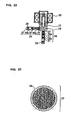
- porous members 32 acting as filters are disposed upstream and downstream of a throttle to reduce refrigerant flow noise as shown in the sectional view of FIG. 21 .
- the porous members 32 are disposed at positions separated from a throttle section, so that they cannot continuously supply a gas/liquid two-phase refrigerant effectively to the throttle section, and thus a problem arises in that refrigerant flow noise is increased.
- FIG. 22 shows a sectional view of the arrangement of a flow controller used in an air conditioning apparatus disclosed in Japanese Unexamined Patent Application Publication JP-A-10-131 681 .
- Honeycomb pipes 37 acting as noise eliminators 36 each having holes communicating both the ends thereof are disposed upstream and downstream of a throttle to reduce refrigerant flow noise.
- FIG. 23 shows a sectional view of the honeycomb pipe.
- An object of the present invention which was made to solve the above problems, is to provide a refrigerating cycle apparatus and an air conditioning apparatus using a throttle device and a flow controller that can greatly reduce refrigerant flow noise and are not clogged by foreign materials in a cycle. Another object of the present invention is to provide a low noise and reliable refrigerating cycle apparatus. Another object of the present invention is to provide a low noise throttle device and flow controller.
- Another object of the present invention is to provide a reliable throttle device and flow controller that are not clogged by foreign materials. Another object of the present invention is to provide a less expensive apparatus having a simple structure. Another object of the present invention is to provide an apparatus that needs not select any particular mounting direction or orientation and has good workability. Another object of the present invention is to provide an easy-to-use air conditioning apparatus.
- a refrigerating cycle apparatus in which a refrigerating cycle is connected circularly through a compressor, a condenser, a flow controller, and an evaporator, respectively, wherein the flow controller comprising a multi-directional valve connected in parallel with a throttle device having at least one porous permeable member communicating in a refrigerant flow direction in a flow path is disposed in a divided intermediate flow path of the evaporator, and a gas/liquid two-phase refrigerant is caused to pass through the throttle section, characterized in that the throttle device comprises an orifice, wherein the porous permeable member is disposed at least at one of the upstream side and the downstream side of the orifice in the refrigerant flow direction, in that a space is defined between the orifice and the porous permeable member, and in that bypass flow paths are formed through foamed metal as the porous permeable members at positions where the bypass flow paths are not superimposed on the orifice, wherein through hole
- a space is disposed at least at one of upstream of the porous permeable member disposed upstream of the orifice and downstream of the porous permeable member disposed downstream of the orifice.
- the multi-directional valve is closed in a reheating/dehumidifying operation.
- the evaporator and the throttle device are in an indoor machine.
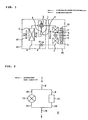
- FIG. 1 is a refrigerant circuit diagram of an air conditioning apparatus showing an example of an embodiment of the present invention, wherein the same components as those of the conventional apparatus are denoted by the same reference numerals.
- numeral 1 denotes a compressor
- 2 denotes a flow-path switching means, for example, a 4-way valve for switching a refrigerant flow between a cooling operation and a heating operation
- 3 denotes an outdoor heat exchanger
- 4 denotes a first flow controller
- 5 denotes a first indoor heat exchanger
- 6 denotes a second flow controller
- 7 denotes a second indoor heat exchanger
- an outdoor unit 33 contains an outdoor fan 40 attached to the outdoor heat exchanger 3
- an indoor unit 34 contains an indoor fan 41 attached to the two indoor heat exchangers.
- a mixed refrigerant R410A composed of R32 mixed with R125 is used as a refrigerant of this refrigerating cycle, and alkylbenzene oil is used as ice machine oil.
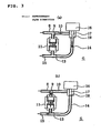
- FIG. 2 is a view showing the arrangement of the secondflow controller 6 of the air conditioning apparatus shown in FIG. 1 , wherein numeral 8 denotes a pipe for connecting the first indoor heat exchanger 5 to the second flow controller 6, 11 denotes a throttle device, 12 denotes a two-way valve, 15 denotes a pipe for connecting the second flow controller 6 to the second indoor heat exchanger, 9 denotes a pipe for connecting the pipe 8 to the throttle device 11, 10 denotes a pipe for connecting the pipe 8 to the two-way valve 12, 13 denotes a pipe for connecting the throttle device 11 to a pipe 15, and 14 denotes a pipe for connecting the two-way valve 12 to the pipe 15.
- numeral 8 denotes a pipe for connecting the first indoor heat exchanger 5 to the second flow controller 6
- 11 denotes a throttle device
- 12 denotes a two-way valve
- 15 denotes a pipe for connecting the second flow controller 6 to the second indoor heat exchanger
- 9 denotes a pipe for connecting the pipe
- the second flow controller 6 is composed of the two-way valve 12 connected in parallel to the throttle device 11 through the pipes.
- FIG. 3 depicts sectional views of the second flow controller 6 shown in FIG. 2 showing the operation thereof, wherein FIG. 3 (a) shows an operating state of the second flow controller 6 in a cooling operation or a heating operation, and FIG.3 (b) shows an operating state of the second flow controller 6 in a reheating/dehumidifying operation.
- numeral 16 denotes an electromagnetic coil
- 17 denotes a valve disc
- 18 denotes a valve seat.
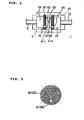
- FIG. 4 is a sectional view in enlargement of the throttle device 11 of the second flow controller 6, wherein 19 denotes an inlet noise eliminating space, 20 denotes a foamed metal disposed on an inlet side; 21 denotes a bypass flow path (through hole) disposed in the inlet side foamed metal, 23 denotes an orifice for performing throttling through a small diameter flow path; 22 denotes a space between the inlet side foamed metal 20 and the orifice 23, 25 denotes an outlet side foamed metal, 24 denotes a space between the orifice 23 and the outlet side foamed metal 25, 26 denotes a bypass flow path (through hole) disposed in the outlet side foamed metal 25, and 27 denotes an outlet side noise eliminating space.
- 19 denotes an inlet noise eliminating space
- 20 denotes a foamed metal disposed on an inlet side
- 21 denotes a bypass flow path (through hole) disposed in the inlet side foamed metal
- Reference numeral 61 denotes a main body with a thickness formed into a cylindrical shape, a polygonal shape, a disc shape, or the like and having the through hole 23 of a small diameter acting as the orifice
- 62 denotes presser members inserted into the main body 61 and having flow paths, for example, pipes for communicating the inside spaces 19 and 26 thereof with the outside.
- the foamed metals 20 and 25 as the porous permeable members disposed at the inlet and outlet of the orifice 23 have the same shape, and FIG. 5 shows a sectional view of them in a flow direction.
- Each foamed metal is composed of the porous permeable member in its entirety.
- vent holes ventilation holes on the surface and in the inside of the porous member through which a fluid can pass
- the diameter of the vent holes is set to 500 ⁇ m and the porosity thereof is set to 92 ⁇ 6% in consideration of the influence of clogging.
- bypass flow path 21 (26) defined through the foamed metal 20 (25) is arranged as a through hole located at one position where it is not superimposed on the orifice 23 and its diameter is equal to or larger than the minimum diameter of 100 ⁇ m of the vent holes, it can obtain an action as a bypass, and thus reliability can be improved by preventing the occurrence of clogging of the foamed metals.
- a through hole having a diameter of 2 mm is provided.
- the foamed metal is made by coating metal powder or alloy powder on urethane foam, burning and eliminating the urethane foam by subjecting it to a heat treatment, and molding the remaining metal into a three-dimensional lattice shape.
- Ni nickel
- Cr chromium
- the area through which the fluid (refrigerant) passes through the porous permeable members 20 can be largely and effectively utilized by the existence of the predetermined gaps 61 c, whereby even if foreign matters are mixed in the fluid (refrigerant), durability to clogging due to foreign matters can be improved. Further, the provision of the positioning projections 61b permits the porous permeable members 20 and the presser members 62 to be positioned easily and reliably, whereby an assembling performance can be improved.
- the ring-shaped positioning projections 61b have an inside diameter set to 10 mm to 20 mm. Further, the inside diameter of the orifice 23 is set to 0.5 mm to 2 mm and the length of the orifice 23 is set to 1 mm to 4 mm; and the dimension of the orifice is determined within the above ranges according to a necessary amount of throttling of the fluid (refrigerant).
- the amount of projection of the positioning projections 61b is set such that the gaps 61c between the porous permeable members 20 and orifice 23 are set within the range of 5 mm or less. In an experiment, a noise reducing effect could be obtained when the gaps 61c were set within the above range.
- the porous permeable members 20 are positioned in the refrigerant (fluid) flow direction by being abutted against the ring-shaped positioning projections 61 b. Further, the porous permeable member 20 is fixed in the state in which it is pressed against the ring-shaped positioning projection 61b side by the presser member 62 having the flow path 13 on the surface thereof opposite to that on the orifice 23 side.
- the presser member 62 has the space 19, which has an inside diameter larger than the inside diameter of the flow path 13 and a predetermined length, is inserted into and joined to the main body 61, and also fixes the porous permeable member in place 20.
- the main body 61 and the presser members 62 are made by cutting or forging metal such as copper, brass, aluminum, stainless steel, or the like.
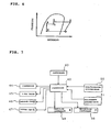
- FIG. 7 shows a block diagram of an overall controller assembled in the air conditioning apparatus.
- the controller 42 is composed of a microprocessor, and the like.
- an operation mode signal for setting an operating state of the air conditioning apparatus a target temperature signal, a target humidity signal, an air flow selecting signal, an operation start/stop signal, and the like are applied to the controller 42 from a remote controller 43 disposed at a location near to, for example, an inhabitant, the controller 42 controls the compressor 1, the 4-way valve 2, the outdoor fan 40, the indoor fan 41, the first flow controller 4, and the second flow controller 6, while monitoring the outputs from a room temperature sensing means 50 and a room humidity sensing means 51.
- Reference numeral 44 denotes a compressor control means for making the operating frequency of the compressor 1 variable
- 45 denotes a 4-way valve control means for switching the 4-way valve 2
- 46 denotes an outdoor fan control means for changing the number of revolutions of the outdoor fan 40
- 47 denotes an indoor/outdoor fan control means for changing the number of revolutions of the indoor fan 40
- 48 denotes a first flow controller control means for controlling the opening/closing of the valve of the first flow controller
- 49 denotes a second flow controller control means for controlling the opening/closing of the valve of the second flow controller.
- FIG. 1 solid arrows show the refrigerant flow in a cooling operation.
- the cooling operation is divided into an ordinary cooling operation corresponding to a case in which both the air conditioning sensible heat load and the air conditioning latent heat load in a room are high at start, in summer, and the like and a dehumidifying operation corresponding to a case in which the latent heat load is large while the air conditioning sensible heat load is low as in an intermediate season, a rainy season, and the like.
- the two-way valve of the second flow controller 6 is put into an open state by the second flow controller control means 49 for controlling the opening/closing of the valve of the second flow controller that receives a command from the controller 42, and the refrigerant is connected from the first indoor heat exchanger to the second indoor heat exchanger with almost no pressure loss.
- a high temperature and high pressure vapor refrigerant ejected from the compressor 1 operating at the number of revolutions corresponding to an air conditioning load passes through the 4-way valve 2, is condensed and liquefied in the outdoor heat exchanger 3, reduced in pressure in the first flow controller 4, and changed to a low pressure two-phase refrigerant, which flows into the first indoor heat exchanger 5 and is evaporated and gasified therein, passes through the second flow controller 6 without a large pressure loss, is evaporated and gasified again in the second indoor heat exchanger 7, and returns to the compressor 1 through the 4-way valve 2 again as a low pressure vapor refrigerant.
- the first flow controller 4 is controlled by the first flow controller control means 48 for controlling the opening and closing of the valve of the first flow controller such that the degree of superheat of the refrigerant at, for example, the intake of the compressor 1 is 10°C.
- heat is drawn from the inside of the room by evaporating the refrigerant in the indoor heat exchanger 5, and the inside of the room is cooled by releasing the heat drawn from the inside of the room to the outside thereof by condensing the refrigerant in the outdoor heat exchanger 3.
- the high pressure and high temperature vapor refrigerant (point A) ejected from the compressor 1 operating at the number of revolutions corresponding to the air conditioning load passes through the 4-way valve 2, exchanges heat with the outside air in the outdoor heat exchanger 3 and is condensed so as to be made into a condensed gas/liquid two-phase refrigerant (point B).
- the high pressure two-phase refrigerant is somewhat reduced in pressure in the first flow controller 4 and flows into the first indoor heat exchanger 5 as an intermediate pressure gas/liquid two-phase refrigerant (point C).
- the intermediate pressure gas/liquid two-phase refrigerant flowed into the first indoor heat exchanger 5 exchanges heat with the indoor air, and is further condensed (point D).
- the gas/liquid two-phase refrigerant ejected from the first indoor heat exchanger flows into the second flow controller 6.
- the refrigerant flows from the inlet pipe 8 of the second flow controller into the throttle device 11 through the connecting pipe 9.
- the refrigerant from the connecting pipe 9 is reduced in pressure in the orifice 23 through the inlet noise eliminating space 19, the inlet side foamed member 20, and the space 22 between the inlet side foamed member 20 and the orifice 23, and is made into a low pressure gas/liquid two-phase refrigerant, which flows into the second indoor heat exchanger 7 (point E) sequentially passing through the space 24 between the orifice 23 and the outlet side foamed metal 25, the outlet side foamed metal 25, the outlet side noise eliminating space 27, and the connecting pipe 13.
- the thickness in the refrigerant flow direction of the foamed metals disposed at the inlet and the outlet of the orifice be 1 mm or more from the view point of flow noise reduction effect and the processing easiness thereof, and the thickness is set to about 3 mm in this embodiment. Further, the inside diameter of the orifice is set to 1 mm and the thickness thereof is set to about 3 mm.
- the refrigerant having flowed into the second indoor heat exchanger 7 is evaporated by removing the sensible and latent heat of indoor air.
- the low pressure vapor refrigerant ejected from the second indoor heat exchanger returns to the compressor 1 again through the 4-way valve 2. Since the indoor air is heated in the first indoor heat exchanger 5 and cooled and dehumidified in the second indoor heat exchanger 7, it is possible to execute the dehumidification while preventing the reduction in the room temperature.
- the dehumidifying operation it is possible to control a blowing-out temperature in a wide range by controlling the heat exchange amount of the outdoor heat exchanger 3 by adjusting the rotational frequency of the compressor 1 and the number of revolutions of the outdoor fan 40 of the outdoor heat exchanger 3 and by controlling the heating amount of the indoor air heated by the first indoor heat exchanger 5. It is also possible to control the heating amount of the indoor air heated by the first indoor heat exchanger 5 by controlling the condensing temperature of the first indoor heat exchanger by controlling the degree of opening of the first flow controller 4 and the number of revolutions of the indoor fan 41. Further, the second flow controller 6 is controlled such that the degree of superheat of the intake refrigerant of the compressor is set to, for example, 10°C.
- a throttling process is composed of the orifice 23. Since the foamed metals arranged as the porous permeable members are disposed on the inlet side and the outlet side of the orifice 23, and the spaces 19 and 27 capable of obtaining a noise eliminating effect are disposed upstream of the inlet side foamed metal 20 and downstream of the outlet side foamed metal 25, respectively, refrigerant flow noise produced when the gas/liquid two-phase refrigerant passes can be greatly reduced.
- the gas/liquid two-phase refrigerant and the liquid refrigerant flowing into the orifice 23 of the throttle device 11 shown in FIG. 4 are rectified when they pass through the countless number of the fine vent holes of the inlet side foamed member 20.
- vapor slags large bubbles
- a gas and a liquid flow intermittently are made into small bubbles
- the flowing state of the refrigerant is made into a uniform gas/liquid two-phase flow (a state in which a vapor refrigerant and a liquid refrigerant are mixed well). Accordingly, the vapor refrigerant and the liquid refrigerant pass through the orifice 23 at the same time, whereby the speed of the refrigerant is not fluctuated, and the pressure thereof is not also fluctuated.
- the porous permeable member since the flow paths formed inside of the porous permeable member such as the inlet side foamed metal 20 are arranged intricately, the porous permeable member has such an effect that the pressure of the refrigerant is fluctuated repeatedly in the porous member and made constant with a part thereof converted into thermal energy. Thus, even if a pressure fluctuation is caused in the orifice 23, the porous permeable member has an effect of absorbing it and is unlike to transmit the influence of the pressure fluctuation to upstream of the orifice. Further, the flow speed of the refrigerant as a high speed gas/liquid two-phase jet stream downstream of the orifice 23 is sufficiently reduced in the inside of the outlet side foamed metal 25 and uniformly distributed. Accordingly, the high speed gas/liquid two-phase jet stream does not collide against a wall surface and no large swirl is produced in the stream, whereby jet stream noise can be also reduced.
- the inlet noise eliminating space 19 disposed on the inlet side of the throttle device 11 can reduce pressure fluctuations having a low frequency that cannot be suppressed by the inlet side foamed metal 20.
- the outlet noise eliminating space 27 is also disposed on the outlet side of the throttle device 11 likewise, it can reduce pressure fluctuations having a low frequency that cannot be suppressed by the outlet side foamed metal 25.
- the porous permeable member 20 is disposed at a position on an approximate linear line with respect to the inlet inside space 19 and the outlet inside space 27 disposed in an approximate linear state with respect to the refrigerant flow direction in the main body 61.
- the flow state of the refrigerant having passed through the porous permeable member 20 is made into a uniform gas/liquid two-phase flow (a state in which a vapor refrigerant is mixed well with a liquid refrigerant), and further the refrigerant can pass through the throttle path (orifice) 23 while maintaining the uniform gas/liquid two-phase flow (the state in which the vapor refrigerant is mixed well with the liquid refrigerant), whereby the speed of the refrigerant is not fluctuated, the pressure thereof is not also fluctuated, and noise is unlike to be produced.
- the porous permeable member 20 is assembled in such a manner that it is abutted against the positioning projections 61b and then pressed by the presser member 62 so as to be sandwiched between the presser member 62 and the positioning projections 61b.
- the presser member 62 is fixed to the main body 61 by press fitting, shrinkage fit, welding, or the like. Therefore, the porous permeable member 20 can be simply and positively positioned when it is assembled, and thus a less expensive throttle device whose assembly time is reduced and whose reliability is improved can be obtained.
- the structure of the throttle device is simple, it is possible to obtain a throttle device at low cost. Further, a countermeasure, which is required in a conventional apparatus, for winding a noise insulating material and a damping material around a throttle device is not necessary, and thus a less expensive refrigerating cycle apparatus can be obtained.
- the cost can be reduced because the countermeasure required in the convention apparatus for winding the noise insulating material and the damping material around the throttle device 6 is unnecessary, and further the recycling performance of the air conditioning apparatus can be improved.
- the problem of the refrigerant flow noise due to the gas/liquid two-phase refrigerant described above is not limited to the air conditioning apparatus and is a general problem common to general refrigerating cycles such as a refrigerator, and the like, the same effect can be obtained by widely applying the throttle device of this embodiment to these general refrigerating cycles.
- the flow characteristics (the relationship between the flow rate of refrigerant and a pressure loss) of the second flow controller 6 in the cooling/dehumidifying operation can be adjusted by adjusting the diameter of the orifice 23, the length of flow path of the orifice through which the refrigerant passes, and the number of the orifices. That is, when a certain amount of refrigerant is flowed with a small pressure loss, it is sufficient to increase the diameter of the orifice, to decrease the length of the flow path thereof, or to use a plurality of the orifices.
- foamed metal has been described as the element for the porous permeable members used on the outlet and the inlet sides of the orifice in the embodiment, the same effect can be obtained even if ceramics, sintered metal, foamed resin, metal wire netting, and the like are used as the element.
- bypass paths (through holes) 21 and 26 are formed through the inlet side foamed metal 20 and the outlet side foamed metal 25, respectively, at the positions where they are not superimposed on the orifice 23, even if the inlet and outlet side foamed metals 20 and 25 are clogged with foreign materials in the refrigerating cycle, it is possible to prevent the reduction of the performance of the throttle device 11 caused by the clogging.
- the space 22 is formed between the inlet side foamed metal 20 and the orifice 23, and the space 24 is formed between the orifice 23 and the outlet side foamed metal 25, almost all the portions of the foamed metals actuate as refrigerant flow paths, whereby a function as the throttle device can be maintained. Since the inlet and outlet side foamed metals 20 and 25 have sufficient reliability as the throttle device, it is possible to provide a sufficiently reliable air conditioning apparatus. While the bypass flow path described in this embodiment is formed into the cylindrical shape and located at one position, the present invention is not limited thereto, and the same effect can be obtained even by a cut-out shaped bypass flow path or a plurality of cylindrical bypass flow paths as shown in FIGS. 12 and 13 .
- FIG. 9 shows the results of measurements of the frequency characteristics of noise produced by a conventional throttle device and those of noise produced by the throttle device of this embodiment.
- the abscissa shows the frequency (Hz) and the ordinate shows the sound pressure (SPL, dBA).
- the dotted line shows the second flow controller of this embodiment, and the solid line shows the conventional second flow controller. It can be found that the sound pressure level of the second flow controller of this embodiment is reduced as compared with the conventional device over the entire frequency range. In particular, it can be found that a great sound pressure level reduction effect can be obtained in the range of from 2000 Hz to 7000 Hz that is well audible to human ears.
- a preset temperature and humidity are set for the air conditioning apparatus when it is operated in order to set a temperature and humidity environment preferred by an inhabitant in a room.
- the inhabitant may directly input the respective set values of the preset temperature and humidity from the remote controller 43 of the indoor unit.
- an optimum temperature and humidity value table which is determined for respective inhabitants who are sensitive to the heat and cold, to children, to elderly persons, and the like, may be stored in the remote controller of the indoor unit so that they can directly input any stored optimum value.
- the indoor unit 34 is provided with sensors for detecting the temperature and humidity of the intake air of the indoor unit to detect the room temperature and humidity.
- the difference between a preset temperature and the current intake air temperature of the room and the difference between a preset humidity and the current intake air humidity of the room are calculated as a temperature difference and a humidity difference, respectively, and the rotational frequency of the compressor 1, the number of revolutions of the outdoor fan, the number of revolutions of the indoor fan, the degree of throttle opening of the first flow control valve 4, and the opening/closing of the second flow control valve 6 of the air conditioning apparatus are controlled such that these differences are finally brought to zero or within the predetermined values.
- the air conditioning apparatus is controlled giving priority to the temperature difference over the humidity difference.
- the controller instructs to set the valve disc 17 of the two-way valve 12 of the second flow control valve 6 at an open position, as shown in FIG. 3(a) . Since the refrigerant passing through the second flow controller has almost no pressure loss, neither the cooling capacity nor the cooling efficiency is reduced. As described above, the second flow controller 6 is set to the open state, and the air conditioning apparatus is operated first such that the temperature difference in the room is preferentially set to zero or within the predetermined value in an ordinary cooling operation.
- the humidity difference is detected.
- the operation of the air conditioning apparatus will be continued as it is.
- the valve disc 17 of the second flow control valve 6 is set to the position where it is in intimate contact with the valve seat 18, as shown in FIG. 3(b) .
- the operation of the air conditioning apparatus is switched to a cooling/dehumidifying operation by throttling the second control valve 12.
- the heating amount of the first indoor heat exchanger 5 is controlled such that the temperature difference in the room can be maintained at zero or within the predetermined value as well as the cooling/ dehumidifying amount of the second indoor heat exchanger 7 is controlled such that the humidity difference is set to zero or within the predetermined value.
- the control of the heating amount of the first indoor heat exchanger 5 is adjusted by the number of revolutions of the outdoor fan of the outdoor heat exchanger 3, the degree of opening of the first flow control valve 4, and the like. Further, the cooling/dehumidifying amount of the second indoor heat exchanger 7 is controlled by the rotational frequency of the compressor 1, the number of revolutions of the indoor fan of the indoor unit 34, and the like.
- alkylbenzene oil that is unlike to be dissolved in the refrigerant is used as ice machine oil in this embodiment, foreign matters that are not dissolved in the refrigerant and foreign materials that are dissolved in the ice machine oil exist in the refrigerating cycle.
- the reliability of the throttle section to clogging can be improved because when these foreign materials are deposited on the foamed metals as the porous permeable members, the ice machine oil that is unlike to be dissolved in the refrigerant has an effect of cleaning the foreign materials when it passes through the foamed metals.
- the heating operation of the air conditioning apparatus of the present invention will be described below.
- the refrigerant circuit constituting the air conditioning apparatus is the same as that shown in, for example, FIG. 1 , so that the arrangement of the second flow controller 6 is the same as that shown in FIG. 3 , and the detailed structure of the throttle device 11 is the same as that shown in FIG. 4 .
- FIG. 1 the flow of the refrigerant in the heating is shown by the broken arrows.
- the controller instructs to set the valve disc 17 of the two-way valve 12 of the second flow control valve 6 in the open position, as shown in FIG. 3(a) .
- the high temperature and high pressure vapor refrigerant ejected from the compressor 1 flows into the second indoor heat exchanger 7 and into the first indoor heat exchanger 5 through the 4-way valve 2, exchanges heat with the indoor air, and is condensed and liquefied.
- the pipe 8 is connected to the pipe 15 through a large opening area as shown in FIG. 3(a) , almost no pressure loss is caused in the refrigerant when it passes through the valve, and thus no decrease in the heating capacity and efficiency is caused by the pressure loss.
- the high pressure liquid refrigerant ejected from the first indoor heat exchanger 5 is reduced in pressure by the first flow controller 4 and made into a gas/liquid two-phase refrigerant, which exchanges heat with the outside air in the outdoor heat exchanger 3 and is evaporated.
- the low pressure vapor refrigerant ejected from the outdoor heat exchanger 3 returns to the compressor 1 again through the 4-way valve 2.
- the degree of opening of the first flow control valve 4 in the ordinary heating operation is controlled such that the degree of superheat of the refrigerant at the outlet of the outdoor heat exchanger 3 is set to, for example, 5 °C.
- the controller instructs to cause the valve disc 17 of the two-way valve 12 of the second flow control valve 6 to be in intimate contact with the valve seat 18, as shown in FIG. 3(b) .
- the high temperature and pressure vapor refrigerant ejected from the compressor 1 flows into the second indoor heat exchanger 7 through the 4-way valve 2, exchanges heat with the indoor air, and is condensed (point E).
- the high pressure liquid refrigerant or the gas/liquid two-phase refrigerant flows into the second flow control valve 6.
- the valve disc 17 of the two-way valve 12 Since the valve disc 17 of the two-way valve 12 is in intimate contact with the valve seat 18 in the second flow control valve 6 as shown in FIG. 3(b) , the high pressure liquid refrigerant or the gas/liquid two-phase refrigerant flows into the throttle device 11 through the second flow path connecting pipe 13, is reduced in pressure and expanded in the orifice 23, and made into a low pressure gas/liquid two-phase refrigerant, which flows into the first indoor heat exchanger 5 through the pipes 9 and 8 (point D).
- the saturation temperature of the refrigerant flowed into the second indoor heat exchanger 5 is equal to or less than the dew point of the indoor air, and the refrigerant is evaporated by drawing the sensible heat and the latent heat of the indoor air (point C).
- the low pressure gas/liquid two-phase refrigerant ejected from the first indoor heat exchanger 5 flows into the first flow control valve 4, is further reduced in pressure, flows into the outdoor heat exchanger 3, exchanges heat with the outside air, and is evaporated.
- the low pressure vapor refrigerant ejected from the outdoor heat exchanger 4 returns to the compressor 1 again through the 4-way valve 2.
- the heating/dehumidifying operation since the indoor air is heated in the second indoor heat exchanger 7 as well as cooled and dehumidified in the first indoor heat exchanger 5, it is possible to dehumidify the room while heating it. Further, in the heating/dehumidifying operation, it is possible to control a blowing-out air temperature in a wide range by controlling the heat exchange amount of the outdoor heat exchanger 3 by adjusting the rotational frequency of the compressor 1 and the number of revolutions of the fan of the outdoor heat exchanger 3 and by controlling the heating amount of the indoor air heated by the first indoor heat exchanger 5.
- the dehumidifying amount of the indoor air dehumidified by the first indoor heat exchanger 5 by controlling the evaporating temperature of the first indoor heat exchanger 5 by adjusting the degree of opening of the first flow control valve 4 and the number of revolutions of the indoor fan.
- the degree of opening of the second flow control valve 6 is controlled such that the degree of supercooling of the refrigerant at the outlet of the second indoor heat exchanger 7 is set to, for example, 10 °C.
- this embodiment employs the second flow control valve in which the orifice 23 of the throttle device 11 is sandwiched between the foamed metals, which permits the dehumidifying operation during heating as well as can prevent the occurrence of refrigerant flow noise in the heating/dehumidifying operation, whereby a comfortable space can be realized as to a temperature and humidity environment and noise.
- the preset temperature, the preset humidity, the intake air temperature, and the intake humidity have been input to the air conditioning apparatus.
- the air conditioning apparatus carries out a high temperature air blowing-out operation for a predetermined period of time, for example, five minutes at the start of heating and then shifts to the ordinary heating operation. Thereafter, switching between the ordinary heating operation and the heating/dehumidifying operation is controlled according to the temperature difference and the humidity difference in the room.
- the compressor 1 is started by putting the valve disc 17 of the two-way valve 12 or the second flow control valve 6 into a throttled state in which the valve disc 17 comes into intimate contact with the valve seat 18, as shown in FIG. 3(b) .
- the evaporating temperature of the first indoor heat exchanger 5 is controlled to become equal to an intake air temperature by adjusting the number of revolutions of the fan of the outdoor heat exchanger 3, the degree of opening of the first flow control valve 4, and the like such that the cooling and dehumidifying capacity in the first indoor heat exchanger 5 is set to zero.
- the air conditioning apparatus shifts to the ordinary heating operation by setting the second flow control valve 6 in the open state, as shown in FIG. 3(a) .
- the rotational frequency of the compressor 1, the number of revolutions of the indoor fan, and the number of revolutions of the outdoor fan are adjusted such that the temperature difference is set to zero or within the predetermined value.
- the humidity difference is detected.
- the heating/dehumidifying operation is carried out by setting the second flow control valve 6 in the throttled state, as shown in FIG. 3(b) .
- the heating amount of the second indoor heat exchanger 7 is controlled such that the temperature difference in the room can be maintained at zero or within the predetermined value as well as the cooling/dehumidifying amount of the first indoor heat exchanger 5 is controlled such that the humidity difference is set to zero or within the predetermined value.
- the heating amount of the second indoor heat exchanger 7 is controlled by the rotational frequency of the compressor 1, the number of revolutions of the fan of the indoor unit 22, and the like. Further, the control of the cooling/dehumidifying amount of the first indoor heat exchanger 5 is adjusted by the number of revolutions of the fan of the outdoor heat exchanger 3, the degree of opening of the first flow control valve 4, and the like.
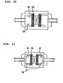
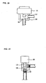
- FIG. 10 is a detailed sectional view showing the structure of another throttle device 11 of the second flow control valve 6 in the air conditioning apparatus of the present invention, wherein the constitutional components that are the same as or similar to those shown in FIG. 4 are denoted by the same reference numerals, and the duplicate description thereof is omitted.
- a convex block 28 is disposed around the inside of the inlet noise eliminating space 19.
- FIG. 11 is a detailed sectional view showing another structure of the throttle device 11 in the second flow control valve 6 of the air conditioning apparatus of the present invention, wherein the constitutional components that are the same as or similar to those shown in FIG. 4 are denoted by the same reference numerals, and the duplicate description thereof is omitted.
- strainers 29 each composed of a woven metal wire are disposed in the inlet and outlet noise eliminating spaces 19 and 27.
- the average pore diameter of the strainers is set smaller than the average pore diameter of 500 micrometers of the inlet and outlet side foamed metals 20 and 25.
- the provision of the strainer 29 composed of the woven metal wire in the inlet noise eliminating space as shown in this embodiment can more reliably prevent the deposit of the foreign materials in the refrigerating cycle on the inlet side foamed metal 20 as compared with the provision of the convex block 28 in the inlet noise eliminating space shown in FIG. 10 .
- the second flow controller having more improved reliability can be obtained, whereby a reliable air conditioning apparatus can be realized.
- R410A is used as the refrigerant of the air conditioning apparatus.
- the refrigerant R410A is an ozone-friendly HFC refrigerant suitable for the conservation of global environment.
- R410A has a smaller pressure loss than that of R22 used conventionally as the refrigerant. This is because it has a larger refrigerant vapor density and thus a slow flow speed.
- R310A is a refrigerant that makes it possible to reduce the size of the vent holes of the porous members used in the throttle device of the second flow control valve 6, whereby a greater refrigerant flow noise reducing effect can be obtained.
- the refrigerant used in the air conditioning apparatus is not limited to R410A, and R407C, R404A, and R507A that are the HFC refrigerants may be used.
- R32 alone, R152a alone, a mixed refrigerant of R32/R124a, and the like that are HFC refrigerants having a small global warming coefficient may be used from the view point of preventing global warming.
- HC refrigerants such as propane, butane, isobutene, etc.
- natural refrigerants such as ammonia, carbon dioxide, ether, and the like, and mixed refrigerants thereof may be used.
- propane, butane, isobutene, and mixed refrigerants thereof have an operating pressure smaller than that of R410A and thus have a small pressure difference between a condensing pressure and an evaporating pressure, which makes it possible to increase the inside diameter of an orifice, thereby reliability to clogging can be more improved.
- the present invention is not limited to the two-way valve, and the second flow controller may use a multidirectional valve, for example, a 3-way valve, by which the same effect can be obtained.
- a method of using the 3-way valve in this case it is possible to include a refrigerant circuit in which a diverted flow path is connected to the outlet side pipe of the second indoor heat exchanger, in addition to the flow path connected in parallel with the throttle device so that the diverted flow path bypasses a refrigerant as a means for reducing the dehumidifying capacity depending upon air conditioning load conditions.
- the refrigerating cycle apparatus of the present invention having the refrigerating cycle in which the compressor, the condenser, the flow controller, and the evaporator are circularly connected, respectively, is provided with the throttle device composed of the multidirectional valve and the orifice connected in parallel with each other, wherein the orifice has the porous permeable members communicating in the refrigerant flow direction in the flow path thereof. Since the gas/liquid two-phase refrigerant is caused to pass through the orifice in this arrangement, there can be obtained an effect of preventing the occurrence of refrigerant flow noise by preventing the breakage of vapor refrigerant slags and refrigerant bubbles to thereby reduce noise and further prevent the clogging due to foreign materials in the cycle.
- the refrigerating cycle apparatus of the present invention includes the orifice in the throttle flow path, an effect of stably adjusting the flow amount of refrigerant can be obtained. Since the refrigerating cycle apparatus is provided with the porous permeable member at least one of upstream and downstream of the orifice in the refrigerant flow direction, there can be obtained an effect of reducing refrigerant flow noise and jet stream noise produced upstream of the orifice by making the size of the vapor slags and the vapor bubbles finer and by making the gas/liquid two-phase refrigerant uniform.
- the pore diameter of the porous permeable members is set to 100 ⁇ m or more, an effect of reducing the refrigerant flow noise and preventing clogging can be obtained. Further, since the thickness of the porous permeable member in the refrigerant flow direction is set to 1 mm or more, an effect of reducing the refrigerant flow noise, preventing the clogging and ensuring a simplified working can be obtained. Further, since at least one through hole having a diameter of at least 100 ⁇ m is formed through each of the porous permeable members, an effect of preventing the clogging and improving reliability can be obtained.
- the refrigerating cycle apparatus of the present invention is provided with the filter disposed at least one of upstream of the porous permeable member disposed upstream of the orifice and downstream of the porous permeable member disposed downstream of the orifice, the clogging of the upstream or downstream side porous permeable member can be prevented, whereby an effect of more improving reliability can be obtained. Since the stagnating portion is disposed upstream of the porous permeable member, the clogging of the upstream side porous permeable member can be prevented, and thus an effect of more improving reliability can be obtained.
- the space is disposed at least one of upstream of the porous permeable member disposed upstream of the orifice and downstream of the porous permeable member disposed downstream of the orifice, there can be obtained an effect of reducing the refrigerant flowing noise produced upstream or downstream of the orifice.
- the refrigerant is composed of the non-azeotropic refrigerant, it is possible to stably control the flow resistance of the refrigerant with low noise and to pass it even if the phase state of the refrigerant changes to various states of a liquid, gas, and two-phase, and thus an effect of stabilizing the refrigerating cycle can be obtained.
- the refrigerant having the vapor density larger than that of R22 is used, an effect of reducing the size of the throttle device can be obtained. Since the refrigerant is composed of the hydrocarbon refrigerant, the inside diameter of the orifice of the throttle section can be increased, and thus an effect of improving reliability can be obtained. Since the multidirectional valve is closed in the reheating/dehumidifying operation, an effect of dehumidifying the room without reducing the room temperature can be obtained.
- the ice machine oil that is easily dissolved in the refrigerant is used, even if foreign matters in the cycle, which are not dissolved in the refrigerant and are dissolved in the ice machine oil, deposit on the porous permeable members, they can be cleaned with the ice machine oil, and thus an effect of improving reliability with respect to clogging can be obtained. Further, since the ice machine oil that is unlike to bc dissolved in the refrigerant is uscd, even if the ice machine oil deposits on the porous permeable members while the compressor is at stop, the deposited ice machine oil can be cleaned with the refrigerant when the compressor is started, and thus an effect of improving reliability can be obtained.
- the second flow controller is composed of the throttle device composed of the multidirectional valve and the orifice connected in parallel with each other, and the orifice has the porous permeable members communicating in the refrigerant flow direction in the flow path thereof.
- the controller for using the throttle device as the refrigerant flow path in the cooling or dehumidifying as well as heating operations there can be obtained an effect of executing comfortable dehumidification while effectively reducing refrigerant flow noise even if the phase state of the refrigerant is changed by the difference of operation modes. Since the controller for using the throttle device as the refrigerant flow path when the heating operation starts is provided, there can be obtained an effect of executing comfortable heating with an enhanced feeling of quick heating by increasing the temperature of blowing-out air.
- the controller for using the throttle section as the refrigerant flow path when the difference between a preset temperature and a room temperature is equal to or larger than a predetermined value in the heating operation is provided, it is possible to blow out high temperature air when the room temperature is sufficiently lower than the preset temperature. Accordingly, there can be obtained an effect of executing comfortable heating without giving a feeling of cold draft.
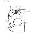
- FIGS. 14 and 15 are front elevational views of an indoor machine, from which a front cover is removed, of the refrigerating cycle apparatus, for example, an air conditioning apparatus, wherein numeral 6 denotes the second flow controller described above, 75 denotes a heat exchanger showing the first indoor heat exchanger 5 or the second indoor heat exchanger 7 disposed in the indoor machine, 74 denotes the controller described in FIG. 7 , 73 denotes a fan motor for driving the fan of the indoor machine, and 88 denotes a cabinet as the outside enclosure of the indoor machine. Further, FIGS. 16 , 17 , and 18 are sectional views of the indoor machine of the air conditioning apparatus.
- 75 denotes the heat exchanger
- 89 denotes a fan
- 88 denotes the cabinet of the indoor machine.
- the throttle device 11 in the second flow controller 6 described in the present invention is disposed in the indoor machine, it can be disposed in the space between the heat exchanger 75 and the fan motor 73, the space between the heat exchanger 75 and the controller 74, and the like in the inside of the cabinet 88 of the indoor machine when viewed at a front position of the cabinet 88, as shown in FIG. 14 .
- the throttle device 11 when viewed at a position on the cross section of the cabinet 88, the throttle device 11 can be disposed on a front surface portion as shown in FIG. 16 , on an upper portion of the cabinet 88 as shown in FIG. 17 , on a rear side of the cabinet as shown in FIG. 18 , and the like. That is, the throttle device of the embodiment can be disposed in any space without the need of any noise insulating material because it operates at low noise. Further, as shown in FIG. 15 , the throttle device 11 can be disposed in the space between the heat exchanger 25 and the cabinet 88. The positions where it can be disposed are the same as those of FIGS. 16 to 18 .
- the throttle device 11 of the present invention operates with low noise, no noise absorbing material is necessary, and thus it can be disposed in any other unused space of the indoor machine of the air conditioning apparatus.
- the throttle device 11 may be disposed in any direction, that is, horizontally, approximately at right angles, obliquely, and the like, with respect to the flow direction of the fluid (refrigerant).
- the fluid (refrigerant) may flow upward from a lower side or downward from an upper side.
Landscapes
- Engineering & Computer Science (AREA)
- Physics & Mathematics (AREA)
- Mechanical Engineering (AREA)
- Thermal Sciences (AREA)
- General Engineering & Computer Science (AREA)
- General Physics & Mathematics (AREA)
- Analytical Chemistry (AREA)
- Power Engineering (AREA)
- Chemical & Material Sciences (AREA)
- Automation & Control Theory (AREA)
- Compression-Type Refrigeration Machines With Reversible Cycles (AREA)
- Lift Valve (AREA)
- Temperature-Responsive Valves (AREA)
- Multiple-Way Valves (AREA)
- Details Of Valves (AREA)
- Electrically Driven Valve-Operating Means (AREA)
Claims (4)
- Kältekreislaufvorrichtung, bei der ein Kältekreislauf durch einen Kompressor (1), einen Kondensator (3), einen Strömungsregler (6) und einen Verdampfer (5, 7) jeweils im Kreislauf verbunden ist,
wobei der Strömungsregler (6), der ein Mehrwegeventil (12) aufweist, das einer Drosseleinrichtung (11) parallelgeschaltet ist, die mindestens ein poröses durchlässiges Element (20, 25) aufweist, das eine Verbindung in einer Kältemittelströmungsrichtung in einem Strömungsweg herstellt, in einem geteilten zwischengeordneten Strömungsweg des Verdampfers (5, 7) angeordnet ist, und ein Gas-/Flüssigkeits-Zweiphasenkältemittel dazu veranlasst wird, den Drosselabschnitt zu passieren,
dadurch gekennzeichnet,
dass die Drosseleinrichtung (11) eine Öffnung (23) aufweist, wobei das poröse durchlässige Element (20, 25) zumindest an einer von einer stromaufwärtigen und einer stromabwärtigen Seite der Öffnung (23) in der Kältemittelströmungsrichtung angeordnet ist,
dass ein Raum (22, 24) zwischen der Öffnung (23) und dem porösen durchlässigen Element (20, 25) gebildet ist, und
dass Umgehungsströmungswege (21, 26) durch geschäumtes Metall als die porösen durchlässigen Elemente (20, 25) an Stellen gebildet sind, an denen die Umgehungsströmungswege (21, 26) der Öffnung (23) nicht überlagert sind, wobei Durchgangsöffnungs-Durchmesser der Umgehungsströmungswege (21, 26) gleich dem oder größer als der Mindestdurchmesser von 100 µm der Lüftungsöffnungen der porösen durchlässigen Elemente (20, 25) sind. - Kältekreislaufvorrichtung nach Anspruch 1,
dadurch gekennzeichnet,
dass ein Raum (19, 27) zumindest an einer Stelle stromaufwärts von dem porösen durchlässigen Element (20, 25), das stromaufwärts von der Öffnung (23) angeordnet ist, und stromabwärts von dem porösen durchlässigen Element (20, 25), das stromabwärts von der Öffnung (23) angeordnet ist, vorgesehen ist. - Kältekreislaufvorrichtung nach einem der Ansprüche 1 und 2,
dadurch gekennzeichnet,
dass das Mehrwegeventil (12) in einem Wiedererwärmungs-/ Entfeuchtungsvorgang geschlossen ist. - Kältekreislaufvorrichtung nach einem der Ansprüche 1 bis 3,
dadurch gekennzeichnet,
dass sich der Verdampfer (5, 7) und die Drosseleinrichtung (11) in einer Innenraummaschine befinden.
Priority Applications (2)
| Application Number | Priority Date | Filing Date | Title |
|---|---|---|---|
| EP08164347.0A EP2003409B1 (de) | 2001-01-31 | 2001-01-31 | Kältekreislaufvorrichtung |
| ES08164347.0T ES2554806T3 (es) | 2001-01-31 | 2001-01-31 | Aparato de ciclo de refrigeración |
Applications Claiming Priority (3)
| Application Number | Priority Date | Filing Date | Title |
|---|---|---|---|
| EP08164347.0A EP2003409B1 (de) | 2001-01-31 | 2001-01-31 | Kältekreislaufvorrichtung |
| EP01902687A EP1367341B1 (de) | 2001-01-31 | 2001-01-31 | Drosselvorrichtung |
| PCT/JP2001/000639 WO2002061350A1 (en) | 2001-01-31 | 2001-01-31 | Refrigerating cycle device, air conditioner, choke, and flow rate controller |
Related Parent Applications (1)
| Application Number | Title | Priority Date | Filing Date |
|---|---|---|---|
| EP01902687A Division EP1367341B1 (de) | 2001-01-31 | 2001-01-31 | Drosselvorrichtung |
Publications (3)
| Publication Number | Publication Date |
|---|---|
| EP2003409A2 EP2003409A2 (de) | 2008-12-17 |
| EP2003409A3 EP2003409A3 (de) | 2009-08-12 |
| EP2003409B1 true EP2003409B1 (de) | 2015-08-26 |
Family
ID=11736965
Family Applications (4)
| Application Number | Title | Priority Date | Filing Date |
|---|---|---|---|
| EP01902687A Expired - Lifetime EP1367341B1 (de) | 2001-01-31 | 2001-01-31 | Drosselvorrichtung |
| EP08164347.0A Expired - Lifetime EP2003409B1 (de) | 2001-01-31 | 2001-01-31 | Kältekreislaufvorrichtung |
| EP08164858A Expired - Lifetime EP2000757B1 (de) | 2001-01-31 | 2001-01-31 | Kältekreislaufvorrichtung |
| EP08164444A Expired - Lifetime EP2000756B1 (de) | 2001-01-31 | 2001-01-31 | Klimaanlage |
Family Applications Before (1)
| Application Number | Title | Priority Date | Filing Date |
|---|---|---|---|
| EP01902687A Expired - Lifetime EP1367341B1 (de) | 2001-01-31 | 2001-01-31 | Drosselvorrichtung |
Family Applications After (2)
| Application Number | Title | Priority Date | Filing Date |
|---|---|---|---|
| EP08164858A Expired - Lifetime EP2000757B1 (de) | 2001-01-31 | 2001-01-31 | Kältekreislaufvorrichtung |
| EP08164444A Expired - Lifetime EP2000756B1 (de) | 2001-01-31 | 2001-01-31 | Klimaanlage |
Country Status (7)
| Country | Link |
|---|---|
| US (2) | US7290567B2 (de) |
| EP (4) | EP1367341B1 (de) |
| CN (2) | CN100498139C (de) |
| AU (1) | AU2001230541B8 (de) |
| DE (1) | DE60142491D1 (de) |
| ES (4) | ES2347761T3 (de) |
| WO (1) | WO2002061350A1 (de) |
Families Citing this family (40)
| Publication number | Priority date | Publication date | Assignee | Title |
|---|---|---|---|---|
| US7146997B2 (en) | 2004-03-29 | 2006-12-12 | Siemens Vdo Automotive Corporation | Regulator with flow diffuser |
| DE102004037537A1 (de) * | 2004-08-03 | 2006-02-23 | Robert Bosch Gmbh | Einrichtung und Verfahren zum Steuern der Strömungsgeschwindigkeit einer Flüssigkeitsströmung in einer Hydraulikleitung |
| ES2706849T3 (es) * | 2004-09-28 | 2019-04-01 | Daikin Ind Ltd | Dispositivo de gestión de ambiente, sistema de gestión de ambiente, método de gestión de ambiente y programa de gestión de ambiente |
| JP4949258B2 (ja) | 2004-11-05 | 2012-06-06 | アルチュリク・アノニム・シルケチ | 冷却装置及び制御方法 |
| KR20070099780A (ko) * | 2006-04-05 | 2007-10-10 | 엘지전자 주식회사 | 냉매배관용 소음저감장치, 그리고 이를 포함하는공기조화기 |
| JP2008095918A (ja) * | 2006-10-16 | 2008-04-24 | Yamaha Marine Co Ltd | サーモエレメント及びこのサーモエレメントを用いたサーモスタット装置 |
| JP5446064B2 (ja) * | 2006-11-13 | 2014-03-19 | ダイキン工業株式会社 | 熱交換システム |
| US20090019886A1 (en) * | 2007-07-20 | 2009-01-22 | Inspired Technologies, Inc. | Method and Apparatus for liquefaction of a Gas |
| CN101358654B (zh) * | 2007-08-02 | 2011-08-03 | 浙江三花股份有限公司 | 电磁阀、空调机及用于电磁阀的节流装置 |
| USD633181S1 (en) * | 2007-09-25 | 2011-02-22 | Fujikin Incorporated | Flow rate controller |
| JP5076950B2 (ja) * | 2008-02-14 | 2012-11-21 | アイシン精機株式会社 | 空気調和装置用ストレーナ |
| CN101561055B (zh) * | 2008-04-18 | 2011-08-24 | 浙江三花股份有限公司 | 电磁阀 |
| EP2428749B1 (de) * | 2009-05-08 | 2019-04-24 | Mitsubishi Electric Corporation | Klimaanlage |
| WO2012035577A1 (ja) * | 2010-09-14 | 2012-03-22 | 三菱電機株式会社 | 室外ユニットの送風機、室外ユニット及び冷凍サイクル装置 |
| AU2011358038B2 (en) * | 2011-01-31 | 2015-01-22 | Mitsubishi Electric Corporation | Air-conditioning apparatus |
| JP2012202624A (ja) * | 2011-03-25 | 2012-10-22 | Toshiba Carrier Corp | 冷凍サイクル装置 |
| JP5665981B2 (ja) * | 2011-06-14 | 2015-02-04 | 三菱電機株式会社 | 空気調和装置 |
| US9651287B2 (en) * | 2011-09-30 | 2017-05-16 | Mitsubishi Electric Corporation | Air-conditioning apparatus |
| US9644872B2 (en) * | 2011-10-24 | 2017-05-09 | Mitsubishi Electric Corporation | Heat pump system, control device, temperature adjustment method, and program |
| JP5450694B2 (ja) * | 2012-03-05 | 2014-03-26 | 本田技研工業株式会社 | 車両用空調装置 |
| JP5891968B2 (ja) * | 2012-06-22 | 2016-03-23 | 株式会社デンソー | 減圧装置 |
| KR101326542B1 (ko) * | 2013-05-28 | 2013-11-07 | 한국기초과학지원연구원 | 압력차를 이용한 자연유도방식의 열교환방법 및 이를 이용한 가스압축기와 히트펌프 |
| US9996091B2 (en) * | 2013-05-30 | 2018-06-12 | Honeywell International Inc. | Comfort controller with user feedback |
| US20140358294A1 (en) * | 2013-05-30 | 2014-12-04 | Honeywell International Inc. | Perceived comfort temperature control |
| DE102013015072A1 (de) * | 2013-07-01 | 2015-01-08 | Liebherr-Hausgeräte Ochsenhausen GmbH | Kühl- und/oder Gefriergerät |
| EP3064868B1 (de) * | 2013-10-29 | 2021-01-20 | Mitsubishi Electric Corporation | Expansionsventil |
| US10054344B2 (en) * | 2014-07-02 | 2018-08-21 | Mitsubishi Electric Corporation | Expansion valve and refrigeration cycle apparatus |
| CH710088B1 (de) * | 2014-09-08 | 2021-05-14 | V Zug Ag | Kühlgerät mit wählbaren Geräuschemissionen. |
| JP6592803B2 (ja) * | 2015-01-16 | 2019-10-23 | 三菱重工コンプレッサ株式会社 | 冷却システム用減圧装置及び冷却システム |
| US10394199B2 (en) | 2015-06-26 | 2019-08-27 | International Business Machines Corporation | Collaborative adjustment of resources within a managed environment |
| KR102620362B1 (ko) * | 2016-08-31 | 2024-01-04 | 삼성전자주식회사 | 공기조화기 |
| DE102017208181A1 (de) * | 2017-03-07 | 2018-09-13 | Robert Bosch Gmbh | Ventil zur Steuerung eines Fluidstroms |
| CN107575939B (zh) * | 2017-09-07 | 2019-10-25 | 珠海格力电器股份有限公司 | 多联机系统及其控制方法 |
| US10920483B2 (en) | 2018-10-25 | 2021-02-16 | Mark Mutchnik | Window seal for preventing water penetration |
| FR3094394B1 (fr) * | 2019-03-28 | 2021-04-09 | Exel Ind | Silencieux de pompe pneumatique, pompe pneumatique comprenant un tel silencieux et installation de projection de produit de revêtement comportant au moins une telle pompe pneumatique |
| CN111457647A (zh) * | 2020-01-16 | 2020-07-28 | 天津商业大学 | 一种减小连续融霜温度波动的冷库控制系统 |
| WO2021153244A1 (ja) * | 2020-01-28 | 2021-08-05 | 三菱電機株式会社 | 空気調和機用消音器及び空気調和機 |
| CN111706964B (zh) * | 2020-05-27 | 2022-08-19 | 青岛海尔空调器有限总公司 | 一种除湿控制方法、装置及除湿设备 |
| CN113587507A (zh) * | 2021-08-13 | 2021-11-02 | 中国科学院上海技术物理研究所 | 一种液氦温区过滤节流蒸发一体化装置 |
| CN120426700A (zh) * | 2025-06-04 | 2025-08-05 | 江苏拓米洛高端装备股份有限公司 | 制冷系统蒸发器出口的过热度辨识方法及制冷系统 |
Family Cites Families (28)
| Publication number | Priority date | Publication date | Assignee | Title |
|---|---|---|---|---|
| US2576610A (en) * | 1944-04-10 | 1951-11-27 | Gen Motors Corp | Restricter |
| US2720756A (en) * | 1954-12-29 | 1955-10-18 | Gen Electric | Heat pump, including fixed flow control means |
| US3150502A (en) * | 1962-07-25 | 1964-09-29 | Singer Co | No-freeze refrigerant control |
| US3270756A (en) * | 1963-04-09 | 1966-09-06 | Hugh L Dryden | Fluid flow control valve |
| DE7338368U (de) * | 1972-10-30 | 1974-04-04 | General Motors Corp | Klimagerät, vorzugsweise für Automobile |
| US3808830A (en) * | 1973-04-16 | 1974-05-07 | Gen Motors Corp | Thermally actuated suction throttling valve |
| US4150696A (en) * | 1974-03-04 | 1979-04-24 | Max-Planck-Gesellschaft Zur Forderung Der Wissenschaften E.V. | Arrangement for suppressing vibrations caused by the flow of a flowable medium |
| US4311020A (en) * | 1980-02-29 | 1982-01-19 | Carrier Corporation | Combination reversing valve and expansion device for a reversible refrigeration circuit |
| JPS57108568A (en) | 1980-12-26 | 1982-07-06 | Nihon Radiator Co | Air conditioning equipment |
| JPS58158276A (ja) | 1982-03-16 | 1983-09-20 | Victor Co Of Japan Ltd | 熱転写型印刷装置の濃度制御装置 |
| JPS6426469A (en) | 1987-07-22 | 1989-01-27 | Canon Kk | Electronic typewriter system |
| US5097866A (en) * | 1990-07-30 | 1992-03-24 | Carrier Corporation | Refrigerant metering device |
| US5083745A (en) * | 1991-01-18 | 1992-01-28 | American Standard Inc. | Incremental electrically actuated valve |
| JPH05141813A (ja) | 1991-11-18 | 1993-06-08 | Mitsubishi Motors Corp | 膨張弁 |
| JPH06207764A (ja) | 1993-01-11 | 1994-07-26 | Mitsubishi Heavy Ind Ltd | 冷凍装置 |
| JPH06241534A (ja) | 1993-02-12 | 1994-08-30 | Mitsubishi Heavy Ind Ltd | 空気調和機 |
| JPH07146032A (ja) | 1993-11-26 | 1995-06-06 | Matsushita Seiko Co Ltd | 膨張弁 |
| JP2883535B2 (ja) | 1994-04-26 | 1999-04-19 | 三洋電機株式会社 | 冷凍装置 |
| JPH07332794A (ja) | 1994-06-02 | 1995-12-22 | Matsushita Seiko Co Ltd | 多室型空気調和装置 |
| JPH09145196A (ja) | 1995-11-22 | 1997-06-06 | Hitachi Ltd | 空気調和機の運転制御方法 |
| JP3605240B2 (ja) | 1996-11-05 | 2004-12-22 | 三菱重工業株式会社 | トンネル掘削機及び掘削方法 |
| JP3955361B2 (ja) | 1997-07-30 | 2007-08-08 | 株式会社日立製作所 | 空気調和機 |
| US5906225A (en) * | 1997-09-10 | 1999-05-25 | General Motors Corporation | Orifice tube type refrigerant expansion valve assembly with combined particulate and noise attenuation filters |
| JP3380452B2 (ja) | 1997-12-26 | 2003-02-24 | 松下電器産業株式会社 | 冷凍サイクル装置および冷凍サイクル装置のレトロフィット方法 |
| JPH11325655A (ja) * | 1998-05-14 | 1999-11-26 | Matsushita Seiko Co Ltd | 消音器および空気調和機 |
| JPH11351706A (ja) | 1998-06-11 | 1999-12-24 | Mitsubishi Electric Corp | 冷媒分配器 |
| JP3428516B2 (ja) | 1999-06-01 | 2003-07-22 | 三菱電機株式会社 | 絞り装置 |
| JP2000346493A (ja) * | 1999-06-01 | 2000-12-15 | Mitsubishi Electric Corp | 絞り装置、冷凍サイクル装置および空気調和装置 |
-
2001
- 2001-01-31 CN CNB2006100958092A patent/CN100498139C/zh not_active Expired - Fee Related
- 2001-01-31 US US10/239,178 patent/US7290567B2/en not_active Expired - Lifetime
- 2001-01-31 EP EP01902687A patent/EP1367341B1/de not_active Expired - Lifetime
- 2001-01-31 CN CNB018075258A patent/CN1304803C/zh not_active Expired - Fee Related
- 2001-01-31 ES ES01902687T patent/ES2347761T3/es not_active Expired - Lifetime
- 2001-01-31 ES ES08164444T patent/ES2373932T3/es not_active Expired - Lifetime
- 2001-01-31 ES ES08164858T patent/ES2392469T3/es not_active Expired - Lifetime
- 2001-01-31 DE DE60142491T patent/DE60142491D1/de not_active Expired - Lifetime
- 2001-01-31 WO PCT/JP2001/000639 patent/WO2002061350A1/ja not_active Ceased
- 2001-01-31 AU AU2001230541A patent/AU2001230541B8/en not_active Ceased
- 2001-01-31 ES ES08164347.0T patent/ES2554806T3/es not_active Expired - Lifetime
- 2001-01-31 EP EP08164347.0A patent/EP2003409B1/de not_active Expired - Lifetime
- 2001-01-31 EP EP08164858A patent/EP2000757B1/de not_active Expired - Lifetime
- 2001-01-31 EP EP08164444A patent/EP2000756B1/de not_active Expired - Lifetime
-
2004
- 2004-08-23 US US10/923,145 patent/US7225630B2/en not_active Expired - Lifetime
Also Published As
| Publication number | Publication date |
|---|---|
| ES2373932T3 (es) | 2012-02-10 |
| CN1912506A (zh) | 2007-02-14 |
| EP1367341B1 (de) | 2010-06-30 |
| EP2000757A2 (de) | 2008-12-10 |
| US7225630B2 (en) | 2007-06-05 |
| ES2392469T3 (es) | 2012-12-11 |
| EP2000757B1 (de) | 2012-09-19 |
| AU2001230541B8 (en) | 2010-03-11 |
| US20050061027A1 (en) | 2005-03-24 |
| AU2001230541B1 (en) | 2002-08-12 |
| CN1422375A (zh) | 2003-06-04 |
| US20030074914A1 (en) | 2003-04-24 |
| ES2554806T3 (es) | 2015-12-23 |
| HK1057085A1 (en) | 2004-03-12 |
| US7290567B2 (en) | 2007-11-06 |
| CN100498139C (zh) | 2009-06-10 |
| EP2003409A3 (de) | 2009-08-12 |
| EP2003409A2 (de) | 2008-12-17 |
| ES2347761T3 (es) | 2010-11-04 |
| DE60142491D1 (de) | 2010-08-12 |
| CN1304803C (zh) | 2007-03-14 |
| EP2000756A3 (de) | 2009-08-26 |
| EP2000757A3 (de) | 2009-11-11 |
| WO2002061350A1 (en) | 2002-08-08 |
| EP2000756B1 (de) | 2011-11-02 |
| EP2000756A2 (de) | 2008-12-10 |
| HK1099658A1 (zh) | 2007-08-17 |
| EP1367341A4 (de) | 2006-07-05 |
| EP1367341A1 (de) | 2003-12-03 |
Similar Documents
| Publication | Publication Date | Title |
|---|---|---|
| EP2003409B1 (de) | Kältekreislaufvorrichtung | |
| WO2012172599A1 (ja) | 空気調和装置 | |
| JP3901103B2 (ja) | 空気調和装置 | |
| JP4103363B2 (ja) | 流量制御装置、冷凍サイクル装置および空気調和装置 | |
| JP3870768B2 (ja) | 空気調和機及び空気調和機の運転方法 | |
| JP3817981B2 (ja) | 冷凍サイクル装置および空気調和装置 | |
| JP4221922B2 (ja) | 流量制御装置、絞り装置及び空気調和装置 | |
| JP2006097901A (ja) | 流量制御弁および冷凍空調装置および流量制御弁の製造方法 | |
| JP2008261626A (ja) | 流量制御装置、絞り装置及び空気調和装置 | |
| AU2004242542B2 (en) | Air conditioning apparatus | |
| EP1291593B1 (de) | Schalldämpfer für Klimaanlage | |
| AU2004202567B2 (en) | Refrigerating cycle apparatus | |
| JP3412602B2 (ja) | 冷凍サイクル装置および空気調和装置 | |
| JP3712355B2 (ja) | 冷凍サイクル装置 | |
| JP3417351B2 (ja) | 絞り装置 | |
| JP2003202167A (ja) | 流量制御弁および冷凍空調装置および流量制御弁の製造方法 | |
| JP4151236B2 (ja) | 流量制御装置及び空気調和装置 | |
| WO2013061365A1 (ja) | 空気調和装置 | |
| CN100436972C (zh) | 流量控制装置和空调装置 | |
| JPH1062032A (ja) | 空気調和機 | |
| HK1099659A1 (zh) | 流量控制装置和空调装置 | |
| HK1099659B (en) | A flow controller and an air conditioning apparatus | |
| HK1099658B (en) | A refrigerating cycle apparatus | |
| JP2003294339A (ja) | 絞り装置 |
Legal Events
| Date | Code | Title | Description |
|---|---|---|---|
| PUAI | Public reference made under article 153(3) epc to a published international application that has entered the european phase |
Free format text: ORIGINAL CODE: 0009012 |
|
| AC | Divisional application: reference to earlier application |
Ref document number: 1367341 Country of ref document: EP Kind code of ref document: P |
|
| AK | Designated contracting states |
Kind code of ref document: A2 Designated state(s): DE ES GB IE IT |
|
| RIN1 | Information on inventor provided before grant (corrected) |
Inventor name: TANABE, YOSHIHIRO Inventor name: SUMIDA, YOSHIHIRO Inventor name: HIRAKUNI, SATOSHI Inventor name: MAKINO, HIROAKI Inventor name: OONISHI, SHIGEKI Inventor name: MOCHIDUKI, ATUSHI |
|
| RIN1 | Information on inventor provided before grant (corrected) |
Inventor name: MOCHIDUKI, ATUSHI Inventor name: HIRAKUNI, SATOSHI Inventor name: SUMIDA, YOSHIHIRO Inventor name: MAKINO, HIROAKI Inventor name: TANABE, YOSHIHIRO Inventor name: OONISHI, SHIGEKI |
|
| PUAL | Search report despatched |
Free format text: ORIGINAL CODE: 0009013 |
|
| AK | Designated contracting states |
Kind code of ref document: A3 Designated state(s): DE ES GB IE IT |
|
| 17P | Request for examination filed |
Effective date: 20100208 |
|
| AKX | Designation fees paid |
Designated state(s): DE ES GB IE IT |
|
| 17Q | First examination report despatched |
Effective date: 20120521 |
|
| GRAP | Despatch of communication of intention to grant a patent |
Free format text: ORIGINAL CODE: EPIDOSNIGR1 |
|
| RIN1 | Information on inventor provided before grant (corrected) |
Inventor name: MOCHIDUKI, ATUSHI Inventor name: OONISHI, SHIGEKI Inventor name: TANABE, YOSHIHIRO Inventor name: MAKINO, HIROAKI Inventor name: HIRAKUNI, SATOSHI Inventor name: SUMIDA, YOSHIHIRO |
|
| RAP1 | Party data changed (applicant data changed or rights of an application transferred) |
Owner name: MITSUBISHI DENKI K.K. |
|
| INTG | Intention to grant announced |
Effective date: 20150310 |
|
| GRAS | Grant fee paid |
Free format text: ORIGINAL CODE: EPIDOSNIGR3 |
|
| GRAA | (expected) grant |
Free format text: ORIGINAL CODE: 0009210 |
|
| AC | Divisional application: reference to earlier application |
Ref document number: 1367341 Country of ref document: EP Kind code of ref document: P |
|
| AK | Designated contracting states |
Kind code of ref document: B1 Designated state(s): DE ES GB IE IT |
|
| REG | Reference to a national code |
Ref country code: GB Ref legal event code: FG4D |
|
| REG | Reference to a national code |
Ref country code: IE Ref legal event code: FG4D |
|
| REG | Reference to a national code |
Ref country code: DE Ref legal event code: R096 Ref document number: 60149549 Country of ref document: DE |
|
| REG | Reference to a national code |
Ref country code: ES Ref legal event code: FG2A Ref document number: 2554806 Country of ref document: ES Kind code of ref document: T3 Effective date: 20151223 |
|
| REG | Reference to a national code |
Ref country code: DE Ref legal event code: R097 Ref document number: 60149549 Country of ref document: DE |
|
| PLBE | No opposition filed within time limit |
Free format text: ORIGINAL CODE: 0009261 |
|
| STAA | Information on the status of an ep patent application or granted ep patent |
Free format text: STATUS: NO OPPOSITION FILED WITHIN TIME LIMIT |
|
| 26N | No opposition filed |
Effective date: 20160530 |
|
| PGFP | Annual fee paid to national office [announced via postgrant information from national office to epo] |
Ref country code: IT Payment date: 20180122 Year of fee payment: 18 |
|
| PGFP | Annual fee paid to national office [announced via postgrant information from national office to epo] |
Ref country code: IE Payment date: 20190109 Year of fee payment: 19 Ref country code: ES Payment date: 20190204 Year of fee payment: 19 |
|
| PG25 | Lapsed in a contracting state [announced via postgrant information from national office to epo] |
Ref country code: IT Free format text: LAPSE BECAUSE OF NON-PAYMENT OF DUE FEES Effective date: 20190131 |
|
| PGFP | Annual fee paid to national office [announced via postgrant information from national office to epo] |
Ref country code: GB Payment date: 20200122 Year of fee payment: 20 |
|
| REG | Reference to a national code |
Ref country code: DE Ref legal event code: R119 Ref document number: 60149549 Country of ref document: DE |
|
| PG25 | Lapsed in a contracting state [announced via postgrant information from national office to epo] |
Ref country code: DE Free format text: LAPSE BECAUSE OF NON-PAYMENT OF DUE FEES Effective date: 20200801 |
|
| PG25 | Lapsed in a contracting state [announced via postgrant information from national office to epo] |
Ref country code: IE Free format text: LAPSE BECAUSE OF NON-PAYMENT OF DUE FEES Effective date: 20200131 |
|
| REG | Reference to a national code |
Ref country code: GB Ref legal event code: PE20 Expiry date: 20210130 |
|
| PG25 | Lapsed in a contracting state [announced via postgrant information from national office to epo] |
Ref country code: GB Free format text: LAPSE BECAUSE OF EXPIRATION OF PROTECTION Effective date: 20210130 |
|
| REG | Reference to a national code |
Ref country code: ES Ref legal event code: FD2A Effective date: 20210603 |
|
| PG25 | Lapsed in a contracting state [announced via postgrant information from national office to epo] |
Ref country code: ES Free format text: LAPSE BECAUSE OF NON-PAYMENT OF DUE FEES Effective date: 20200201 |