EP2000680B1 - Agent de formation d'un film de revêtement pour vis taraudeuse, procédé de préparation de l'agent de formation du film de revêtement, procédé de formation d'un film de revêtement prévu sur la circonférence extérieure d'une vis taraudeuse à l'aide de l'agent de formation de film de revêtement et vis taraudeuse dotée d'un fil - Google Patents
Agent de formation d'un film de revêtement pour vis taraudeuse, procédé de préparation de l'agent de formation du film de revêtement, procédé de formation d'un film de revêtement prévu sur la circonférence extérieure d'une vis taraudeuse à l'aide de l'agent de formation de film de revêtement et vis taraudeuse dotée d'un fil Download PDFInfo
- Publication number
- EP2000680B1 EP2000680B1 EP07849901A EP07849901A EP2000680B1 EP 2000680 B1 EP2000680 B1 EP 2000680B1 EP 07849901 A EP07849901 A EP 07849901A EP 07849901 A EP07849901 A EP 07849901A EP 2000680 B1 EP2000680 B1 EP 2000680B1
- Authority
- EP
- European Patent Office
- Prior art keywords
- tapping screw
- coating layer
- coating agent
- coating
- coating film
- Prior art date
- Legal status (The legal status is an assumption and is not a legal conclusion. Google has not performed a legal analysis and makes no representation as to the accuracy of the status listed.)
- Not-in-force
Links
- 238000010079 rubber tapping Methods 0.000 title claims abstract description 183
- 239000011248 coating agent Substances 0.000 title claims abstract description 135
- 238000000034 method Methods 0.000 title claims description 25
- 238000000576 coating method Methods 0.000 title description 24
- 239000003795 chemical substances by application Substances 0.000 title description 19
- 239000011247 coating layer Substances 0.000 claims abstract description 172
- FIASKJZPIYCESA-UHFFFAOYSA-L calcium;octacosanoate Chemical compound [Ca+2].CCCCCCCCCCCCCCCCCCCCCCCCCCCC([O-])=O.CCCCCCCCCCCCCCCCCCCCCCCCCCCC([O-])=O FIASKJZPIYCESA-UHFFFAOYSA-L 0.000 claims abstract description 63
- UTOPWMOLSKOLTQ-UHFFFAOYSA-N octacosanoic acid Chemical compound CCCCCCCCCCCCCCCCCCCCCCCCCCCC(O)=O UTOPWMOLSKOLTQ-UHFFFAOYSA-N 0.000 claims abstract description 56
- 239000000839 emulsion Substances 0.000 claims abstract description 41
- 229920005992 thermoplastic resin Polymers 0.000 claims abstract description 36
- 239000000203 mixture Substances 0.000 claims abstract description 32
- 230000001050 lubricating effect Effects 0.000 claims abstract description 21
- XLYOFNOQVPJJNP-UHFFFAOYSA-N water Substances O XLYOFNOQVPJJNP-UHFFFAOYSA-N 0.000 claims abstract description 19
- 229920005989 resin Polymers 0.000 claims description 27
- 239000011347 resin Substances 0.000 claims description 27
- 239000004094 surface-active agent Substances 0.000 claims description 23
- 230000009477 glass transition Effects 0.000 claims description 11
- 239000000463 material Substances 0.000 claims description 10
- 239000000049 pigment Substances 0.000 claims description 10
- 238000007654 immersion Methods 0.000 claims description 7
- 239000007787 solid Substances 0.000 claims description 7
- 230000001747 exhibiting effect Effects 0.000 claims description 6
- 238000001035 drying Methods 0.000 claims description 2
- 238000012360 testing method Methods 0.000 description 33
- 230000015572 biosynthetic process Effects 0.000 description 26
- 230000002093 peripheral effect Effects 0.000 description 18
- 239000000853 adhesive Substances 0.000 description 14
- 235000013872 montan acid ester Nutrition 0.000 description 13
- 239000000314 lubricant Substances 0.000 description 12
- 238000005259 measurement Methods 0.000 description 12
- 235000014113 dietary fatty acids Nutrition 0.000 description 11
- 239000000428 dust Substances 0.000 description 11
- 238000011156 evaluation Methods 0.000 description 11
- 239000000194 fatty acid Substances 0.000 description 11
- 229930195729 fatty acid Natural products 0.000 description 11
- 239000003094 microcapsule Substances 0.000 description 11
- 241000894007 species Species 0.000 description 10
- 239000001993 wax Substances 0.000 description 10
- 230000001070 adhesive effect Effects 0.000 description 9
- 150000004665 fatty acids Chemical class 0.000 description 9
- 239000011575 calcium Substances 0.000 description 8
- 239000011230 binding agent Substances 0.000 description 7
- 239000004925 Acrylic resin Substances 0.000 description 6
- 229920000178 Acrylic resin Polymers 0.000 description 6
- 159000000007 calcium salts Chemical class 0.000 description 6
- 230000000694 effects Effects 0.000 description 6
- 239000000344 soap Substances 0.000 description 6
- VHOCUJPBKOZGJD-UHFFFAOYSA-N triacontanoic acid Chemical compound CCCCCCCCCCCCCCCCCCCCCCCCCCCCCC(O)=O VHOCUJPBKOZGJD-UHFFFAOYSA-N 0.000 description 6
- 235000013871 bee wax Nutrition 0.000 description 5
- 239000012166 beeswax Substances 0.000 description 5
- 235000013869 carnauba wax Nutrition 0.000 description 5
- 239000004203 carnauba wax Substances 0.000 description 5
- 229920006332 epoxy adhesive Polymers 0.000 description 5
- XMHIUKTWLZUKEX-UHFFFAOYSA-N hexacosanoic acid Chemical compound CCCCCCCCCCCCCCCCCCCCCCCCCC(O)=O XMHIUKTWLZUKEX-UHFFFAOYSA-N 0.000 description 5
- 238000002360 preparation method Methods 0.000 description 5
- 238000009864 tensile test Methods 0.000 description 5
- -1 alcohol ester Chemical class 0.000 description 4
- 239000006185 dispersion Substances 0.000 description 4
- 230000032050 esterification Effects 0.000 description 4
- 238000005886 esterification reaction Methods 0.000 description 4
- 230000008018 melting Effects 0.000 description 4
- 238000002844 melting Methods 0.000 description 4
- 239000000758 substrate Substances 0.000 description 4
- OKTJSMMVPCPJKN-UHFFFAOYSA-N Carbon Chemical compound [C] OKTJSMMVPCPJKN-UHFFFAOYSA-N 0.000 description 3
- 239000004952 Polyamide Substances 0.000 description 3
- 230000002411 adverse Effects 0.000 description 3
- 230000000052 comparative effect Effects 0.000 description 3
- 239000010410 layer Substances 0.000 description 3
- 229920002647 polyamide Polymers 0.000 description 3
- PUPZLCDOIYMWBV-UHFFFAOYSA-N (1R)-1,3-butanediol Natural products CC(O)CCO PUPZLCDOIYMWBV-UHFFFAOYSA-N 0.000 description 2
- OYPRJOBELJOOCE-UHFFFAOYSA-N Calcium Chemical compound [Ca] OYPRJOBELJOOCE-UHFFFAOYSA-N 0.000 description 2
- LYCAIKOWRPUZTN-UHFFFAOYSA-N Ethylene glycol Chemical compound OCCO LYCAIKOWRPUZTN-UHFFFAOYSA-N 0.000 description 2
- 229920000180 alkyd Polymers 0.000 description 2
- 239000012298 atmosphere Substances 0.000 description 2
- 229910052791 calcium Inorganic materials 0.000 description 2
- CJZGTCYPCWQAJB-UHFFFAOYSA-L calcium stearate Chemical compound [Ca+2].CCCCCCCCCCCCCCCCCC([O-])=O.CCCCCCCCCCCCCCCCCC([O-])=O CJZGTCYPCWQAJB-UHFFFAOYSA-L 0.000 description 2
- 239000008116 calcium stearate Substances 0.000 description 2
- 235000013539 calcium stearate Nutrition 0.000 description 2
- 238000004132 cross linking Methods 0.000 description 2
- 230000008021 deposition Effects 0.000 description 2
- 239000002270 dispersing agent Substances 0.000 description 2
- 239000010439 graphite Substances 0.000 description 2
- 229910002804 graphite Inorganic materials 0.000 description 2
- 229910052751 metal Inorganic materials 0.000 description 2
- 239000002184 metal Substances 0.000 description 2
- 239000002245 particle Substances 0.000 description 2
- 230000001105 regulatory effect Effects 0.000 description 2
- 239000003381 stabilizer Substances 0.000 description 2
- 125000005480 straight-chain fatty acid group Chemical group 0.000 description 2
- 238000010998 test method Methods 0.000 description 2
- REZQBEBOWJAQKS-UHFFFAOYSA-N triacontan-1-ol Chemical compound CCCCCCCCCCCCCCCCCCCCCCCCCCCCCCO REZQBEBOWJAQKS-UHFFFAOYSA-N 0.000 description 2
- KMEHEQFDWWYZIO-UHFFFAOYSA-N triacontyl hexadecanoate Chemical compound CCCCCCCCCCCCCCCCCCCCCCCCCCCCCCOC(=O)CCCCCCCCCCCCCCC KMEHEQFDWWYZIO-UHFFFAOYSA-N 0.000 description 2
- 235000019386 wax ester Nutrition 0.000 description 2
- 206010012335 Dependence Diseases 0.000 description 1
- GRYLNZFGIOXLOG-UHFFFAOYSA-N Nitric acid Chemical compound O[N+]([O-])=O GRYLNZFGIOXLOG-UHFFFAOYSA-N 0.000 description 1
- 229910000831 Steel Inorganic materials 0.000 description 1
- 239000002253 acid Substances 0.000 description 1
- 239000002280 amphoteric surfactant Substances 0.000 description 1
- 239000003945 anionic surfactant Substances 0.000 description 1
- AXCZMVOFGPJBDE-UHFFFAOYSA-L calcium dihydroxide Chemical compound [OH-].[OH-].[Ca+2] AXCZMVOFGPJBDE-UHFFFAOYSA-L 0.000 description 1
- 239000000920 calcium hydroxide Substances 0.000 description 1
- 229910001861 calcium hydroxide Inorganic materials 0.000 description 1
- 125000004432 carbon atom Chemical group C* 0.000 description 1
- 239000003093 cationic surfactant Substances 0.000 description 1
- 238000013329 compounding Methods 0.000 description 1
- 238000005336 cracking Methods 0.000 description 1
- 230000006735 deficit Effects 0.000 description 1
- 229940126534 drug product Drugs 0.000 description 1
- 238000004993 emission spectroscopy Methods 0.000 description 1
- 150000002148 esters Chemical class 0.000 description 1
- 238000004299 exfoliation Methods 0.000 description 1
- 239000000945 filler Substances 0.000 description 1
- 235000021588 free fatty acids Nutrition 0.000 description 1
- 230000007062 hydrolysis Effects 0.000 description 1
- 238000006460 hydrolysis reaction Methods 0.000 description 1
- 230000001976 improved effect Effects 0.000 description 1
- 239000003077 lignite Substances 0.000 description 1
- 238000005461 lubrication Methods 0.000 description 1
- 238000004519 manufacturing process Methods 0.000 description 1
- 229910017604 nitric acid Inorganic materials 0.000 description 1
- 239000002736 nonionic surfactant Substances 0.000 description 1
- 238000005192 partition Methods 0.000 description 1
- 239000000825 pharmaceutical preparation Substances 0.000 description 1
- 239000000843 powder Substances 0.000 description 1
- 239000010453 quartz Substances 0.000 description 1
- 239000011342 resin composition Substances 0.000 description 1
- 238000007790 scraping Methods 0.000 description 1
- VYPSYNLAJGMNEJ-UHFFFAOYSA-N silicon dioxide Inorganic materials O=[Si]=O VYPSYNLAJGMNEJ-UHFFFAOYSA-N 0.000 description 1
- 239000002904 solvent Substances 0.000 description 1
- 239000010959 steel Substances 0.000 description 1
- 239000000126 substance Substances 0.000 description 1
- 229920001187 thermosetting polymer Polymers 0.000 description 1
Images

Classifications
-
- F—MECHANICAL ENGINEERING; LIGHTING; HEATING; WEAPONS; BLASTING
- F16—ENGINEERING ELEMENTS AND UNITS; GENERAL MEASURES FOR PRODUCING AND MAINTAINING EFFECTIVE FUNCTIONING OF MACHINES OR INSTALLATIONS; THERMAL INSULATION IN GENERAL
- F16B—DEVICES FOR FASTENING OR SECURING CONSTRUCTIONAL ELEMENTS OR MACHINE PARTS TOGETHER, e.g. NAILS, BOLTS, CIRCLIPS, CLAMPS, CLIPS OR WEDGES; JOINTS OR JOINTING
- F16B33/00—Features common to bolt and nut
- F16B33/06—Surface treatment of parts furnished with screw-thread, e.g. for preventing seizure or fretting
-
- C—CHEMISTRY; METALLURGY
- C10—PETROLEUM, GAS OR COKE INDUSTRIES; TECHNICAL GASES CONTAINING CARBON MONOXIDE; FUELS; LUBRICANTS; PEAT
- C10M—LUBRICATING COMPOSITIONS; USE OF CHEMICAL SUBSTANCES EITHER ALONE OR AS LUBRICATING INGREDIENTS IN A LUBRICATING COMPOSITION
- C10M173/00—Lubricating compositions containing more than 10% water
- C10M173/02—Lubricating compositions containing more than 10% water not containing mineral or fatty oils
-
- C—CHEMISTRY; METALLURGY
- C10—PETROLEUM, GAS OR COKE INDUSTRIES; TECHNICAL GASES CONTAINING CARBON MONOXIDE; FUELS; LUBRICANTS; PEAT
- C10M—LUBRICATING COMPOSITIONS; USE OF CHEMICAL SUBSTANCES EITHER ALONE OR AS LUBRICATING INGREDIENTS IN A LUBRICATING COMPOSITION
- C10M2201/00—Inorganic compounds or elements as ingredients in lubricant compositions
- C10M2201/02—Water
-
- C—CHEMISTRY; METALLURGY
- C10—PETROLEUM, GAS OR COKE INDUSTRIES; TECHNICAL GASES CONTAINING CARBON MONOXIDE; FUELS; LUBRICANTS; PEAT
- C10M—LUBRICATING COMPOSITIONS; USE OF CHEMICAL SUBSTANCES EITHER ALONE OR AS LUBRICATING INGREDIENTS IN A LUBRICATING COMPOSITION
- C10M2201/00—Inorganic compounds or elements as ingredients in lubricant compositions
- C10M2201/085—Phosphorus oxides, acids or salts
-
- C—CHEMISTRY; METALLURGY
- C10—PETROLEUM, GAS OR COKE INDUSTRIES; TECHNICAL GASES CONTAINING CARBON MONOXIDE; FUELS; LUBRICANTS; PEAT
- C10M—LUBRICATING COMPOSITIONS; USE OF CHEMICAL SUBSTANCES EITHER ALONE OR AS LUBRICATING INGREDIENTS IN A LUBRICATING COMPOSITION
- C10M2207/00—Organic non-macromolecular hydrocarbon compounds containing hydrogen, carbon and oxygen as ingredients in lubricant compositions
- C10M2207/10—Carboxylix acids; Neutral salts thereof
- C10M2207/12—Carboxylix acids; Neutral salts thereof having carboxyl groups bound to acyclic or cycloaliphatic carbon atoms
- C10M2207/1203—Carboxylix acids; Neutral salts thereof having carboxyl groups bound to acyclic or cycloaliphatic carbon atoms used as base material
-
- C—CHEMISTRY; METALLURGY
- C10—PETROLEUM, GAS OR COKE INDUSTRIES; TECHNICAL GASES CONTAINING CARBON MONOXIDE; FUELS; LUBRICANTS; PEAT
- C10M—LUBRICATING COMPOSITIONS; USE OF CHEMICAL SUBSTANCES EITHER ALONE OR AS LUBRICATING INGREDIENTS IN A LUBRICATING COMPOSITION
- C10M2209/00—Organic macromolecular compounds containing oxygen as ingredients in lubricant compositions
- C10M2209/02—Macromolecular compounds obtained by reactions only involving carbon-to-carbon unsaturated bonds
- C10M2209/08—Macromolecular compounds obtained by reactions only involving carbon-to-carbon unsaturated bonds containing monomers having an unsaturated radical bound to a carboxyl radical, e.g. acrylate type
- C10M2209/084—Acrylate; Methacrylate
-
- F—MECHANICAL ENGINEERING; LIGHTING; HEATING; WEAPONS; BLASTING
- F16—ENGINEERING ELEMENTS AND UNITS; GENERAL MEASURES FOR PRODUCING AND MAINTAINING EFFECTIVE FUNCTIONING OF MACHINES OR INSTALLATIONS; THERMAL INSULATION IN GENERAL
- F16B—DEVICES FOR FASTENING OR SECURING CONSTRUCTIONAL ELEMENTS OR MACHINE PARTS TOGETHER, e.g. NAILS, BOLTS, CIRCLIPS, CLAMPS, CLIPS OR WEDGES; JOINTS OR JOINTING
- F16B25/00—Screws that cut thread in the body into which they are screwed, e.g. wood screws
Definitions
- the present invention relates to an agent for forming a coating layer on a tapping screw (hereinafter the agent may be referred to as a "(tapping screw) coating agent"); to a method for preparing the coating agent; a method for forming a coating layer so as to cover the periphery of a tapping screw by use of the coating agent; and to a tapping screw having thereon a coating layer formed from the coating agent.
- apping screw collectively refers to screws which allow self-tapping.
- the tapping screws are screwed into prepared holes formed in the workpiece while tapping female threads, so that the parts are supported between the workpiece and the heads of the tapping screws.
- a mounting method is generally employed for, for example, mounting small parts of an electronic device on a workpiece.
- attention must be paid to the treatment of powdery chips (i.e., forming chips) generated during screwing of a tapping screw into a prepared hole of a workpiece.
- a tapping screw when a tapping screw is screwed into a prepared hole of a workpiece, as the tapping screw enters the prepared hole, a female thread is gradually formed at the inner wall of the prepared hole, whereby shavings are continuously generated through formation of the female thread.
- the shavings are scraping of the material of the workpiece.
- the thus-generated shavings may be scattered and deposited on a part to be mounted or on the workpiece.
- the shavings deposited on the part or the workpiece may adversely affect other parts mounted on the workpiece.
- male-thread-forming chips When, for example, an electronic circuit or a similar part is mounted on the workpiece, scattering of chips generated during formation of a female thread (hereinafter the chips may be referred to as “female-thread-forming chips") may cause short-circuit of the electronic circuit, resulting in, for example, breakage or burnout of devices.
- a tapping screw having means for preventing deposition of female-thread-forming chips on parts or a workpiece has been proposed and disclosed in, for example, Japanese Patent Application Laid-Open (kokai) No. 2002-70824 , No. 2002-257120 , or No. 2002-257121 .
- the tapping screws proposed in the aforementioned patent documents include a male threaded portion (i.e., shank) having, on the periphery thereof, a coating layer.
- the coating layer is formed through application of a resin adhesive agent containing microcapsules encapsulating an epoxy adhesive, or application of a coating material.
- US 2002/037400 A1 discloses metal plate coated with a lubricating resin is coated with a lubricating resin having a modified polyamide and a crosslinking curing agent of the modified polyamide at least one side face of the metal plate.
- the compounding ratio of the modified polyamide and the above-described crosslinking curing agent is preferably 60:40 to 15:85 by mass ratio converted to solid content.
- an inorganic powder filler may be added to the resin composition.
- JP 2005 2901120 A discloses a torque coefficient stabilizing agent which is applied on a material member having a screwed part such as a fastened bolt to reduce an ambient temperature dependence of the axial force of the screwed part at the time of fastening.
- the torque coefficient stabilizing agent is composed of an aqueous dispersion containing 0.5-20 wt% graphite and 5-30 wt% wax.
- the material member for screwing having the screwed part and at least a part of the surface of which is covered with a covering material containing a mixture of graphite and wax is presented.
- the coating layer is formed from a resin adhesive agent containing densely dispersed microcapsules encapsulating an epoxy adhesive.
- the coating layer may exhibit an adhesion effect on female-thread-forming chips.
- the coating layer may hold female-thread-forming chips generated during screwing of the tapping screw; i.e., the coating layer may function so as to prevent scattering of female-thread-forming chips on parts or the workpiece.
- a coating layer in particular, an effective component for forming the coating layer
- a male threaded portion i.e., shank
- the coating layer is required to have the following characteristics for exhibiting the function of capturing female-thread-forming chips.
- the coating layer is required to have a characteristic such that it is strongly bonded to the periphery of the shank of the tapping screw and is never removed therefrom until completion of screwing of the tapping screw into the prepared hole of the workpiece.
- the coating layer is required to have a characteristic such that it expresses its potential adhesive function at a desired timing by means of pressure applied thereto during gradual formation of a female thread until completion of screwing of the tapping screw into the prepared hole of the workpiece.
- the coating layer is required to have a characteristic such that it exhibits a lubricating function to such an extent that the tapping screw can be smoothly screwed into the prepared hole of the workpiece under a predetermined operation load.
- the coating layer formed from the aforementioned resin adhesive agent containing densely dispersed microcapsules encapsulating an epoxy adhesive poses problems described below.
- the adhesion strength of the coating layer to the shank of the tapping screw cannot be evaluated.
- the adhesion strength of the coating layer is not considered in the aforementioned patent documents.
- the coating layer cannot be regarded as having the aforementioned first characteristic.
- the coating agent for forming the coating layer is a resin adhesive agent containing densely dispersed microcapsules encapsulating an epoxy adhesive.
- the coating agent is thought to be prepared by, for example, dispersing numerous epoxy-adhesive-containing microcapsules in a resin emulsion as an effective coating component.
- the size of resin particles of the resin emulsion which is an effective coating component is as small as about 0.01 ⁇ m, whereas the size of microcapsules is very large (i.e., 1 ⁇ m or more).
- the coating agent poses a problem in that a large number of microcapsules cannot be uniformly dispersed in the resultant coating layer; i.e., the microcapsules are not uniformly distributed over the surface of a metallic member to which the coating layer is bonded.
- the thickness of a coating layer formed must be increased.
- the coating layer is likely to separate from the screw in an early stage of screwing of the screw into a prepared hole of a workpiece; i.e., the coating layer cannot maintain strong adhesion to the screw until completion of screwing of the screw into the prepared hole of the workpiece.
- the coating layer cannot achieve expression of its potential adhesive function at a desired timing by means of pressure applied thereto upon formation of a female thread until completion of screwing of the tapping screw into the prepared hole of the workpiece. That is, since the coating layer does not have the aforementioned second characteristic, the coating layer cannot exhibit the function of capturing female-thread-forming chips (chips produced during formation of a female thread) at a desired timing, and scattering of the chips is inevitable.
- a main object of the present invention is to provide a coating agent capable of forming a coating layer which has at least the aforementioned three characteristics, and which functions so as to prevent scattering of female-thread-forming chips generated during formation of a female thread through screwing of a tapping screw into a prepared hole of a workpiece.
- Another object of the present invention is to provide a method for forming the coating layer on the periphery of a tapping screw by use of the coating agent.
- Yet another object of the present invention is to provide a tapping screw having thereon the coating layer (hereinafter the tapping screw may be referred to as a "coated tapping screw").
- the present invention is directed to a tapping screw coating agent; to a method for preparing the coating agent; to a method for forming a coating layer on the periphery of a tapping screw by use of the coating agent; and to a tapping screw having thereon a coating layer formed from the coating agent.
- the present invention provides a tapping screw coating agent for forming, on the periphery of a tapping screw, a coating layer exhibiting a lubricating function and a function of capturing female-thread-forming chips, characterized in that the coating agent is a composition comprising, as primary components, calcium montanate or a calcium-montanate-containing montanic acid species mixture, a thermoplastic resin emulsion, and water, wherein the amount of calcium montanate or the montanic acid species mixture is 3 to 20 wt.%, and the amount of the thermoplastic resin emulsion is 1 to 10 wt.% as a solid content.
- calcium montanate or a calcium-montanate-containing montanic acid species mixture which is a component of the coating agent of the present invention, refers to, for example, calcium montanate, a calcium salt produced from a mixture of montanic acid and a montanic acid ester, or a mixture of calcium montanate and a montanic acid ester.
- calcium montanate may collectively refer to these species.
- the thermoplastic resin emulsion which is a component of the coating agent, preferably contains a resin having a glass transition point of 50°C or lower.
- a surfactant for dispersing calcium montanate in water is used.
- the coating agent preferably contains a surfactant in an amount equal to or greater than that required for dispersing calcium montanate in water.
- the surfactant content of the coating, agent is preferably 1 to 9 wt.%.
- the coating agent preferably contains a pigment.
- the pigment content of the coating agent is preferably 0.1 to 0.5 wt.%.
- the present invention also provides a method for forming a coating layer on a tapping screw; i.e., a method for forming a coating layer on the periphery of a tapping screw by use of the coating agent of the present invention, characterized in that the method comprises immersing numerous tapping screws placed in an immersing container in a coating agent having a temperature adjusted to 10 to 30°C and a viscosity adjusted to 3 to 13 mPa ⁇ S (at 25°C); removing an excessive amount of the coating agent deposited on each tapping screw after completion of immersion; and drying the coating agent deposited on each tapping screw, to thereby form a coating layer on the periphery of the tapping screw.
- the present invention also provides a tapping screw having thereon a coating layer formed by applying the coating agent of the present invention to the tapping screw through immersion, characterized in that the tapping screw has a coating layer of virtually uniform thickness on the entirety of a shank of the screw, which is a male threaded portion, and on the entirety of a head of the screw, which is united with the shank, wherein the coating layer exhibits a lubricating function during screwing of the tapping screw, and a function of capturing female-thread-forming chips generated through screwing of the tapping screw.
- the coating layer formed on the entirety thereof preferably has a thickness of 1 to 6 ⁇ m.
- the coating layer formed on the entirety of the tapping screw preferably assumes a color different from that of the material of the tapping screw.
- the tapping screw When the coated taping screw having thereon a coating layer formed from the coating agent of the present invention is employed for, for example, fixing a part on a workpiece, the tapping screw is screwed into a prepared hole provided in the workpiece.
- the tapping screw is employed in such a manner, since the coating layer formed on the periphery of the tapping screw has small thickness and high adhesion strength, the coating layer is note removed away from the shank, which is male threaded portion, of the tapping screw until completion of screwing of the tapping screw into the prepared hole.
- the coating layer exhibits a proper lubricating function during screwing of the tapping screw, and also exhibits a proper function of capturing female-thread-forming chips through expression of the adhesive function of the coating layer by means of pressure and heat applied thereto during formation of a female thread during screwing.
- the coated tapping screw of the present invention is screwed into a prepared hole of a workpiece under a virtually consistent load; i.e., screwing of the tapping screw can be smoothly carried out.
- female-thread-forming chips generated during formation of a female thread during screwing of the tapping screw are held, at a desired timing, in the coating layer by its adhesive function that is expressed by means of pressure and heat applied to the coating layer during formation of the female thread. Therefore, scattering of female-thread-forming chips on mounted parts or the workpiece is reliably prevented.
- employment of the tapping screw can prevent scattering of female-thread-forming chips, and can avoid adverse effects of female-thread-forming chips on the mounted parts or the workpiece.
- Calcium montanate contained in the coating agent of the present invention functions so that a coating layer formed from the coating agent exhibits lubricity.
- calcium stearate calcium soap
- calcium montanate exhibits strong waxy characteristics and excellent adhesion to the surface of a metallic member. Therefore, employment of calcium montanate, which serves as a lubricant, can considerably reduce the amount of the thermoplastic resin emulsion employed, which serves as a binder for attaining strong adhesion of a coating layer to the surface of a tapping screw. This is the reason why the coating agent of the present invention can form a thin coating layer which is strongly bonded to the peripheral surface of a tapping screw.
- thermoplastic resin emulsion which is a component of the coating agent of the present invention, serves as a binder for bonding calcium montanate which is an effective coating component to the surface of a tapping screw. Also the thermoplastic resin emulsion functions so as to hold shavings generated during formation of a female thread. Therefore, the resin contained in the emulsion must have excellent capturing performance and adhesion.
- the coating agent of the present invention employs, as the resin constituting the thermoplastic resin emulsion, a thermoplastic resin having a glass transition point of 50°C or lower.
- the present invention employs a thermoplastic resin having a glass transition point of 50°C or lower.
- a coating layer formed from the coating agent is prevented from melting in an atmosphere at about 80°C, and can exhibit the function of capturing shavings generated during formation of a female thread.
- a tapping screw having the coating layer is employed for mounting parts on a workpiece, thereby producing a device, the coating layer is prevented from melting at high temperature in the produced device, and also prevented from falling from the tapping screw.
- the resin employed in the coating agent is preferably an acrylic resin.
- a surfactant is used for dispersing calcium montanate in water.
- the surfactant is incorporated into the coating agent in an amount equal to or in excess of that required for dispersing calcium montanate in water, the excess portion of the surfactant serves as a leveling agent for improving applicability of the coating agent (i.e., the ability of the agent to be uniformly applied), thereby reducing irregularities of the resultant coating layer.
- the coating layer can express its potential adhesive function at a desired timing corresponding to generation of shavings during formation of a female thread.
- the coating layer exhibits further improved effect of capturing female-thread-forming chips.
- the type of the surfactant employed in the present invention so long as it can uniformly disperse calcium montanate and the thermoplastic resin emulsion in water, to thereby prepare a uniform aqueous dispersion.
- the surfactant include an anionic surfactant, a cationic surfactant, an amphoteric surfactant, and a nonionic surfactant.
- the coating layer of virtually uniform thickness is formed on the entirety of the shank, which is a male threaded portion, of the screw, and on the entirety of the head of the screw, which is united with the shank. Therefore, as described above in detail, when the tapping screw is screwed into a workpiece, the tapping screw effectively exhibits a lubricating function, as well as a function of capturing female-thread-forming chips.
- the coating layer formed on the tapping screw can reduce friction coefficient during screwing, and can reduce variation in friction coefficient, to thereby attain a consistent, low screwing torque during formation of a female thread.
- the coating layer is formed on a seating surface of a collar of the tapping screw, after seating of the collar seating surface onto a target part, variation in axial force generated by a set torque can be considerably reduced.
- a tapping screw having thereon a coating layer formed from a pigment-containing coating agent is advantageous in that, the difference in color between the coating layer and the material of the tapping screw facilitates visually distinguishing the tapping screw from a tapping screw having no such a coating layer.
- a coating layer on a tapping screw of the present invention numerous tapping screws can be subjected to a coating treatment at one time without using any special jig, since the coating agent employed in the method has low viscosity, and a coating layer is formed on the entire peripheral surface of each tapping screw. Therefore, according to the coating method, a coating layer can be formed on each tapping screw in an economically advantageous manner. In addition, according to the coating method, a coating layer having such a small thickness that can secure screw accuracy can be formed on a male threaded portion having a small diameter, and poor operation of screwing a small-diameter tapping screw into a workpiece can be prevented.
- the present invention relates to a tapping screw coating agent; to a method for forming a coating layer on a tapping screw by use of the coating agent; and to a tapping screw having thereon a coating layer formed from the coating agent.
- the tapping screw coating agent of the present invention is a composition containing, as primary components, calcium montanate or a calcium-montanate-containing montanic acid species mixture; i.e., calcium montanate, a mixture of calcium montanate and a montanic acid ester, or a calcium salt produced from a mixture of montanic acid and a montanic acid ester (these species will be collectively referred to as "calcium montanate"), a thermoplastic resin emulsion, and water.
- the coating agent preferably contains an excess surfactant.
- the amount of calcium montanate is 3 to 20 wt.%
- the amount of the thermoplastic resin emulsion is 1 to 10 wt.% as a solid content.
- the thermoplastic resin emulsion preferably contains a resin having a glass transition point of 50°C or lower.
- Montanic acid is a trivial name for a straight-chain fatty acid predominantly containing a C28 fatty acid, or a C28 fatty acid and a C24-C34 fatty acid.
- Calcium montanate exhibits a lubricating function.
- Calcium montanate, which is a component of the coating agent of the present invention exhibits strong waxy characteristics and excellent adhesion to the surface of a metallic member, as compared with calcium stearate, which is generally employed as a lubricant.
- the coating agent employs calcium montanate as a component
- the amount of the below-described thermoplastic resin emulsion, which is employed as a binder for bonding calcium montanate to the peripheral surface of a tapping screw can be considerably reduced, as compared with the case where a generally employed lubricant is incorporated into the coating agent. Therefore, the coating agent, which contains calcium montanate as a component, can form a thin coating layer on the entire peripheral surface of a tapping screw.
- the coating agent of the present invention employs calcium montanate as a component exhibiting a lubricating function.
- Montanic acid is a straight-chain fatty acid predominantly containing a C28 fatty acid and containing a C24-C34 fatty acid.
- Examples of similar fatty acids and waxes thereof include carnauba wax, beeswax, and melissic acid.
- melissic acid which has a long carbon chain (30 carbon atoms), is considered to exhibit a function similar to that of montanic acid.
- melissic acid is a rare fatty acid which is known to be present only in apple skin, the fatty acid is expensive, and, at present, use of the fatty acid is limited to a drug product. Therefore, employment of such an expensive fatty acid as a component of the coating agent is economically very disadvantageous.
- Carnauba wax or beeswax contains cerotic acid (C26) as a primary component. However, carnauba wax or beeswax contains a free fatty acid in a small amount. Carnauba wax contains cerotic acid in the form of an ester with myricyl alcohol, whereas beeswax contains a large amount of myricyl palmitate. Therefore, employment of carnauba wax or beeswax as a component of the coating agent results in an increase in cost, as compared with the case of employment of montanic acid.
- cerotic acid C26
- carnauba wax or beeswax contains a free fatty acid in a small amount.
- Carnauba wax contains cerotic acid in the form of an ester with myricyl alcohol, whereas beeswax contains a large amount of myricyl palmitate. Therefore, employment of carnauba wax or beeswax as a component of the coating agent results in an increase
- montanic acid can be easily extracted from brown coal with a solvent, and has been commercially available in the form of montanic acid wax, montanic acid ester wax, or partially saponified montanic acid ester wax. Therefore, montanic acid or a montanic acid ester is inexpensive and readily available. Employment of such an inexpensive, readily available fatty acid as a component of the coating agent is economically very advantageous.
- calcium montanate which is employed as a component of the coating agent, may be calcium montanate alone.
- calcium montanate employed in the coating agent may be a mixture of calcium montanate and a montanic acid ester, or a calcium salt produced from a mixture of montanic acid and a montanic acid ester.
- the reason why such a mixture-form calcium montanate may be employed is that it is functionally comparable to calcium montanate alone, and is, readily available (i.e., commercially available in the form of, for example, montanic acid wax or montanic acid ester wax).
- thermoplastic resin emulsion which is a component of the coating agent of the present invention, serves as a binder for bonding calcium montanate which is an effective coating component to the peripheral surface of a tapping screw.
- the thermoplastic resin emulsion also functions so as to hold shavings generated during formation of a female thread. Therefore, the resin contained in the emulsion must have excellent capturing performance and adhesion. No particular limitation is imposed on the type of the resin, so long as the resin exhibits both these properties.
- the resin is preferably a thermoplastic resin having a glass transition point of 50°C or lower.
- a coating layer formed from the coating agent is prevented from melting in an atmosphere at about 80°C, and can ensure the function of capturing shavings generated during formation of a female thread.
- the coating layer is prevented from melting, which would otherwise be cased by high temperature during mounting, and also prevented from falling from the tapping screw.
- the resin employed in the coating agent is preferably an acrylic resin.
- the tapping screw coating agent of the present invention is a composition containing, as primary components, calcium montanate, a thermoplastic resin emulsion, and water.
- the amount of calcium montanate is 3 to 20 wt.%
- the amount of the thermoplastic resin emulsion is 1 to 10 wt.% as a solid content.
- the coating agent contains an excess surfactant serving as a leveling agent
- the excess surfactant content of the coating agent is 0.4 to 2 wt.%
- the total surfactant content of the coating agent is 1 to 9 wt.%.
- Calcium montanate which is a component of the coating agent of the present invention, functions so that a coating layer formed from the coating agent exhibits lubricity.
- a generally employed lubricant e.g., calcium soap
- calcium montanate exhibits strong waxy characteristics and excellent adhesion to the surface of a metallic member. Therefore, employment of calcium montanate, which serves as a lubricant, can considerably reduce the amount of the thermoplastic resin emulsion employed, which serves as a binder for attaining strong adhesion of a coating layer to the entire peripheral surface of a tapping screw.
- thermoplastic resin emulsion which serves as a binder, contributes to formability of a coating layer, but impairs the lubricating function of calcium montanate. Therefore, from the viewpoint of such a negative contribution, preferably, the amount of the thermoplastic resin emulsion, which is employed as a component of the coating agent, is reduced to the smallest possible extent.
- the present invention employs calcium montanate, which exhibits strong waxy characteristics and excellent adhesion to the surface of a metallic member.
- the coating agent of the present invention can form a coating layer which has a thickness as small as 1 to 6 ⁇ m, and which is strongly bonded to the peripheral surface of a tapping screw.
- the amount of calcium montanate is regulated to 3 to 20 wt.%, and the amount of the thermoplastic resin emulsion is regulated to 1 to 10 wt.% as a solid content.
- the coating agent of the present invention preferably contains, as a component, a pigment which assumes an appropriate color. No particular limitation is imposed on the type of the pigment employed, so long as the color of a coating layer formed on the peripheral surface of a tapping screw applied by the pigment-containing coating agent can be visually distinguished from the color of the material of the tapping screw.
- the coating agent of the present invention may be prepared through any known method. Basically, the coating agent is prepared through the following procedure: montanic acid or a mixture of montanic acid and a montanic acid ester (hereinafter the mixture may be referred to as a "montanic acid species mixture”) is saponified with calcium hydroxide, to thereby prepare calcium montanate or a calcium salt of the montanic acid species mixture; and the thus-prepared calcium montanate or calcium salt of the montanic acid species mixture and a thermoplastic resin emulsion are uniformly dispersed in water by use of a surfactant.
- montanic acid or a mixture of montanic acid and a montanic acid ester hereinafter the mixture may be referred to as a "montanic acid species mixture”
- the thus-prepared calcium montanate or calcium salt of the montanic acid species mixture and a thermoplastic resin emulsion are uniformly dispersed in water by use of a surfactant.
- the coating agent is prepared so that the amounts of the respective components are as follows: calcium montanate or a calcium salt of a montanic acid species mixture: 3 to 20 wt.%, a thermoplastic resin emulsion: 1 to 10 wt.% (as a solid content), a surfactant: 1 to 9 wt.%, and water: balance.
- Preparation of the thermoplastic resin emulsion and dispersion of calcium montanate in water require a surfactant in an amount of 0.6 to 7 wt.%.
- an excess surfactant (0.4 to 2 wt.%) is not used for such dispersion but used as a leveling agent for enabling the coating agent to be uniformly applied.
- the coating agent of the present invention is basically prepared through the aforementioned method.
- a commercially available lubricant e.g., montanic acid wax or montanic acid ester wax
- calcium montanate i.e., calcium montanate or a mixture of calcium montanate and a montanic acid ester
- any of the following commercially available lubricants may be employed as calcium montanate.
- montanic-acid-containing lubricants examples include "Wax OP (registered trademark)” and “Wax O (registered trademark)” (products of Clariant GmbH) and “Wax OP (registered trademark)” (product of BASF).
- a lubricant is a mixture of Ca soap of montanic acid and a dihydric alcohol ester having a high degree of esterification.
- such a mixture contains a 1,2-ethanediol and/or 1,3-butanediol ester having a degree of esterification of 90% or more.
- the Ca soap content of the mixture is about 45 wt.%, which corresponds to a Ca content of about 1.5 wt.%.
- the coating method of the present invention is employed.
- numerous tapping screws contained in an immersion container are immersed at one time in a coating agent having a temperature adjusted to 10 to 30°C and a viscosity adjusted to 3 to 13 mPa-S (at 25°); subsequently, an excessive amount of the coating agent deposited on each tapping screw is removed after completion of immersion; and finally, the coating agent deposited on each tapping screw is dried, to thereby form a coating layer on the entire periphery of the tapping screw.
- the coating agent of the present invention which is employed for forming a coating layer on a tapping screw
- the amount of the thermoplastic resin emulsion, which serves as a binder can be reduced, since calcium montanate, which is a component of the coating agent, exhibits excellent properties contributing to formation of a coating layer. Therefore, the viscosity of the coating agent can be reduced.
- a coating layer can be formed on a tapping screw so that a cruciform recess (drive recess) provided in the head of the screw, into which the tip end of a screwdriver fits, is not filled with the coating agent. Therefore, the coating method of the present invention can form a coating layer on the entire peripheral surface of a tapping screw.
- the coating method exhibits the below-described effects intrinsic to the method, and realizes production of an excellent tapping screw as described below.
- a conventional coating agent has high viscosity.
- the region on which a coating layer is formed is limited to only the shank, which is a male threaded portion, of the tapping screw, at least where a coating layer must be formed.
- a single tapping screw is held by means of a special, exclusive jig, and only the shank of the thus-held tapping screw is immersed in the coating agent, to thereby form a coating layer on the peripheral surface of the shank.
- a coating layer can be formed on the entire peripheral surface of a tapping screw without causing any problem, since the coating agent employed in the method has low viscosity. Therefore, numerous tapping screws contained in an immersion container can be immersed at one time in the coating agent, and coating layers can be formed on the peripheries of the numerous tapping screws at one time without using special exclusive jig.
- a coating layer can be formed on each tapping screw in an economically advantageous manner.
- a coating layer having such a small thickness can secure screw accuracy, and it is possible to form the coating layer on a male threaded portion having a small diameter. Further, poor operation of screwing a small-diameter tapping screw into a workpiece can be prevented.
- the tapping screw of the present invention has thereon a coating layer formed from the coating agent of the present invention.
- the tapping screw has a coating layer of virtually uniform thickness on the entire peripheral surface of the shank, which is a male threaded portion, of the screw, and on the entire peripheral surface of the head of the screw, which is united with the shank.
- the coating layer exhibits a lubricating function during screwing of the tapping screw, and a function of capturing female-thread-forming chips generated through screwing of the tapping screw.
- FIG. 1 schematically shows a tapping screw 10 according to an embodiment of the present invention.
- the tapping screw 10 includes a shank (male threaded portion) 11; a head 12 which is united with the shank 11; and a collar 13 formed at the boundary between the shank 11 and the head 12.
- the head 12 has, on the top surface thereof, a cross recess (a drive recess 14) into which the tip end of a screwdriver fits.
- the tapping screw 10 has, on the entire peripheral surface thereof, a coating layer 20 formed from the coating agent of the present invention.
- the coating layer 20 is schematically shown by a two-dot chain line.
- the coating layer 20 consists of a first coating layer portion 21 formed on the entire peripheral surface of the shank 11; a second coating layer portion 22 formed on the entire peripheral surface of the head 12; and a third coating layer portion 23 formed on the entire peripheral surface of the collar 13.
- the coating layer 20 assumes a color different from that of the material of the tapping screw 10, and the coating layer 20 has a thickness of 1 to 6 ⁇ m.
- FIG. 2 schematically shows a common tapping screw 10A and a mode of use thereof.
- the tapping screw 10A When a non-illustrated screwdriver fitted into a drive recess 14 formed in the top of a head 12 of the tapping screw 10A is rotated, the tapping screw 10A is screwed into a prepared hole 31 provided in a workpiece 30, to thereby form a female thread on the inner wall of the prepared hole 31; i.e., the tapping screw 10A taps a female thread in the prepared hole 31.
- a target part is fastened and mounted on the workpiece 30 so as to be sandwiched between the surface of the workpiece 30 and the seating surface of the collar 13 of the tapping screw 10A.
- female-thread-forming chips 33 are generated.
- the female-thread-forming chips 33 continuously generate as the female thread is formed until screwing of the tapping screw 10A is stopped.
- the thus-generated female-thread-forming chips 33 are scattered on the workpiece 30.
- the tapping screw 10 of the present invention has, on the entire peripheral surface thereof, the coating layer 20 exhibiting a lubrication function and a function of capturing the female-thread-forming chips 33. Therefore, by virtue of the lubricating function of the first coating layer portion 21, the tapping screw 10 is smoothly screwed into the prepared hole 31 by means of a virtually constant operational force, to thereby form a female thread on the inner wall of the prepared hole 31.
- the female-thread-forming chips 33 generated during formation of the female thread are held in the coating layer portion by its adhesive function that is expressed by means of pressure and heat applied thereto during formation of the female thread, whereby scattering of the female-thread-forming chips 33 on the workpiece 30 is prevented.
- the coating layer 20 formed on the tapping screw 10 has small thickness and high adhesion strength, no removal or peeling of the coating layer from the shank 11 (i.e., male threaded portion) of the tapping screw 10 occurs until completion of screwing of the tapping screw 10 into the prepared hole.
- the coating layer 20 exhibits a proper lubricating function during screwing of the tapping screw 10, and also exhibits a proper function of capturing the female-thread-forming chips 33 through expression of the adhesive function of the coating layer at a desired timing by means of pressure and heat applied thereto during formation of the female thread during screwing.
- the tapping screw 10 is screwed into the prepared hole 33 of the workpiece 30 under a low and virtually constant load. Accordingly, screwing of the tapping screw 10 can be smoothly carried out at a low and constant torque.
- the female-thread-forming chips 33 generated during formation of the female thread by screwing are held, at a desired timing, in the coating layer 20 by its adhesive function that is expressed by means of pressure and heat applied to the coating layer 20 during formation of the female thread. Therefore, scattering of the female-thread-forming chips 33 on mounted parts or the workpiece 30 is reliably prevented.
- the coating layer 20 can prevent adverse effects of scattering of the female-thread-forming chips 33 on the mounted parts or the workpiece 30.
- the seating surface of the collar 13, which serves as a partition between the shank 11 and the head 12 of the tapping screw 10 is seated onto a portion of the target part mounted on the surface of the workpiece 30. Since the third coating layer portion 23 constituting the coating layer 20 is formed on the seating surface of the collar 13 of the tapping screw 10, after seating of the collar 13 of the tapping screw 10 onto the target part, variation in axial force generated at a set torque can be considerably reduced.
- Example 1 a plurality of coating agents containing calcium montanate as a component were prepared, and coating layers formed from the thus-prepared agents were tested in terms of adhesion strength to a metallic member, tackiness (capturing performance), friction coefficient, and amount of cut dust generated.
- Table 1 shows components of the thus-prepared coating agents, and the amounts of the components.
- Table 2 shows the results of tests.
- Component A "Wax OP" (registered trademark) ⁇ calcium montanate (wt.%)
- Component B thermoplastic resin emulsion Resin component: b1 ⁇ acrylic-alkyd resin (no Tg) (wt.%) b2 ⁇ acrylic resin (Tg: -5°C) (wt.%) b3 ⁇ acrylic resin (Tg: 6°C) b4 ⁇ acrylic-styrene resin (Tg: 47°C) (wt.%)
- Component C leveling agent (wt.%) ⁇ Troysol LAC (registered trademark)
- Component D pigment (wt.%)
- Component E water (containing a surfactant) (wt.%)
- Coating layer thickness: (g/m 2 ) ⁇ 1g/m 2 corresponds to a thickness of 1 ⁇ m Table 2 (Properties
- AB/AB 6B 10 cm 0.155/x 1.17// ⁇ 7 177/196 186.3 AB/B ⁇ 6B 10 cm 0.120/ ⁇ 0.96/ ⁇ 8 206/216 210.8 AB/B ⁇ 6B 10 cm 0.123/ ⁇ 1.04/ ⁇ Bonding strength: unit N/cm 2 Breakage position: AB ⁇ interfacial breakage B ⁇ breakage of cohesion and interfacial breakage between sub-layers in a coating layer Pencil hardness: evaluation ratings (6H to 6B) Friction coefficient: evaluation by three ratings (O, ⁇ , any ⁇ ). Amount of cut dust generated: unit mg, evaluation by three ratings (O. ⁇ , and ⁇ ).
- test samples 1 to 8 eight types of coating agents (test samples 1 to 8) were prepared by use of a commercial lubricant ("Wax OP" (registered trademark), product of Clariant GmbH) as calcium montanate, a thermoplastic resin emulsion, a surfactant (serving as a dispersant for dispersing calcium montanate in water, or as a leveling agent), a pigment, and water.
- Wax OP registered trademark
- surfactant serving as a dispersant for dispersing calcium montanate in water, or as a leveling agent
- component A represents “Wax OP”
- component B b1, b2, b3, or b4
- component C a surfactant serving as a leveling agent
- component D a pigment
- component E water containing a surfactant
- “Wax OP” (component A) is a mixture of Ca soap of montanic acid and a dihydric alcohol ester having a high degree of esterification, and contains a 1,2-ethanediol and/or 1,3-butanediol ester having a degree of esterification of 90% or more.
- the Ca soap content of the mixture is about 45 wt.%, which corresponds to a Ca content of about 1.5 wt.%.
- thermoplastic resin emulsion (component B)
- component b1 represents an emulsion containing an acrylic-alkyd resin (no glass transition point)
- component b2 an emulsion containing an acrylic resin (glass transition point: -5°C)
- component b3 an emulsion containing an acrylic resin (glass transition point: 6°C)
- component b4" an emulsion containing an acrylic-styrene resin (glass transition point: 47°C).
- the leveling agent (component C) is Troysol LAC (registered trademark) (product of Troy Chemical Corporation).
- Water (component E) contains, in an amount of 0.5 wt.%, a surfactant serving as a dispersant for dispersing calcium montanate in water.
- Coating layer thickness (g/m 2 ) shown in Table 1 is the thickness of a coating layer formed on a test piece subjected to the below-described tests.
- a coating layer thickness of 1 g/m 2 corresponds to about 1 ⁇ m.
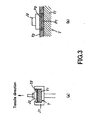
- each of the above-prepared coating agents was applied to a surface of a steel plate (substrate), to thereby prepare a test piece having thereon a coating layer, and the test piece was subjected to the tensile bonding strength test method according to JIS K5600-5-7 (see FIG. 3a ).
- the thus-measured bonding strength was regarded as adhesion strength.
- the unit of bonding strength is "N/cm 2 .”
- the position of breakage of the coating layer was determined through the breakage position test method according to JIS K5400 (see FIG. 3b ).
- a test piece T was placed on a lower jig J1 for tensile testing so that the test piece T did not move upward.
- An upper jig J2 for tensile testing ( ⁇ 20 mm) was attached, by use of an adhesive, to the surface of a coating layer t2 formed on the top surface of a substrate t1 of the test piece T.
- a groove was formed in the coating layer t2 along the circumference of the upper jig J2 so as to reach the substrate t1, so that a portion of the coating layer t2 attached to the upper jig J2 was separated from the remaining portion; and then the attached portion of the coating layer t2 was subjected to tensile testing by means of a tensile tester at a tensile rate of 10 mm/min, to thereby measure the bonding strength of the coating layer t2.
- the position of breakage of the coating layer was determined as shown in FIG. 3(b) .
- Position P1 denotes interfacial breakage between the coating layer t2 and the substrate t1 of the test piece T.
- Position P2 denotes breakage of cohesion in the coating layer t2 and interfacial breakage between sub-layers in the coating layer t2.
- the bonding strength and breakage position as determined through the tensile bonding strength test are shown in the column “Adhesion strength” of Table 2.
- the tensile bonding strength test was carried out at two sites per a single test piece. These test data are shown in the sub-columns "Measured value” and "Breakage position" of the column “Bonding strength.” In each sub-column, test data corresponding the two sites of the test piece are separately listed by a slash (/).
- a test piece T was prepared so as to have the same configuration as that employed in the aforementioned measurement of adhesion strength.
- the tackiness of the coating layer t2 of the test piece T was evaluated on the basis of pencil hardness as measured through the pencil hardness test according to JIS K5400 8,4,2, and impact resistance as measured through the impact resistance test according to JIS 5600-5-3. Pencil hardness was evaluated by scores (6 H to 6B), and the unit of impact value used for evaluation of impact resistance is "cm.”
- a test piece T was prepared so as to have the same configuration as that employed in the aforementioned measurement of adhesion strength.
- thread friction coefficient and seating surface friction coefficient were calculated through "Method of tightening test for threaded fasteners" according to JIS B1014, and total friction coefficient was calculated as friction coefficient by use of the following formula 1.
- the thus-calculated friction coefficient was evaluated by three ratings (O, ⁇ , and ⁇ ). The results of measurement and evaluation of friction coefficient are shown in the column “Friction coefficient/evaluation" of Table 2.
- Tf tightening torque
- Ff tightening axial force
- P thread pitch
- D nominal screw diameter
- Dw equivalent diameter of friction torque on the seating surface
- the tapping screw having a coating layer formed from each test sample shown in Table 1 and formed on the entire periphery thereof was screwed into a prepared hole of a workpiece.
- the thus-generated cut dust (female-thread-forming chips) was completely collected, and the thus-collected cut dust was entirely transferred into a quartz beaker.
- a mixed acid (HCl + HNO 3 ) was added to the beaker for hydrolysis, and the volume of the mixture was adjusted to 50 mL, to thereby prepare a solution for measurement.
- the thus-prepared solution was subjected to ICP emission spectrometry for quantitative determination of the amount of cut dust.
- the thus-measured amount of cut dust was evaluated by three ratings (O, ⁇ , and ⁇ ).
- the results of measurement and evaluation of the amount of cut dust are shown in the column "Amount of cut dust generated/evaluation" of Table 2.
- the unit of amount of cut dust generated is "mg.”
- the coating agent of the present invention can form, on the periphery of a tapping screw, a coating layer which exhibits a lubricating function during formation of a female thread, and a function of capturing female-thread-forming chips.
- a coating layer exhibiting these functions can be readily formed on the periphery of a tapping screw in an economically advantageous manner.
- the coated tapping screw of the present invention realizes, through smooth screwing, mounting of various parts on a workpiece, and can prevent scattering of female-thread-forming chips generated during screwing of the tapping screw into the workpiece.
Landscapes
- Chemical & Material Sciences (AREA)
- Engineering & Computer Science (AREA)
- General Engineering & Computer Science (AREA)
- Chemical Kinetics & Catalysis (AREA)
- General Chemical & Material Sciences (AREA)
- Oil, Petroleum & Natural Gas (AREA)
- Organic Chemistry (AREA)
- Mechanical Engineering (AREA)
- Application Of Or Painting With Fluid Materials (AREA)
- Lubricants (AREA)
- Paints Or Removers (AREA)
- Laminated Bodies (AREA)
Claims (8)
- Agent de revêtement pour vis taraudeuse pour former, sur la périphérie d'une vis taraudeuse (10), une couche de revêtement (20) présentant une fonction de lubrification et une fonction de capture de copeaux (33) de formation d'un filetage femelle, caractérisé par le fait que l'agent de revêtement est une composition comprenant, comme composants primaires, du montanate de calcium ou un mélange d'espèces d'acide montanique contenant du montanate de calcium, une émulsion de résine thermoplastique et de l'eau, la quantité de montanate de calcium ou du mélange d'espèces d'acide montanique étant de 3 à 20 % en poids, et la quantité de l'émulsion de résine thermoplastique étant de 1 à 10 % en poids en tant que teneur en matières solides.
- Agent de revêtement pour vis taraudeuse selon la revendication 1, dans lequel l'émulsion de résine thermoplastique, qui est un composant de l'agent de revêtement, contient une résine ayant un point de transition vitreuse de 50°C ou moins.
- Agent de revêtement pour vis taraudeuse selon l'une des revendications 1 ou 2, qui contient un tensioactif dans une quantité de 1 à 9 % en poids.
- Agent de revêtement pour vis taraudeuse selon l'une des revendications 1, 2 ou 3, qui contient un pigment dans une quantité de 0,1 à 0,5 % en poids.
- Procédé de formation d'une couche de revêtement sur la périphérie d'une vis taraudeuse (10) à l'aide d'un agent de revêtement pour vis taraudeuse tel que défini à l'une quelconque des revendications 1 à 4, caractérisé par le fait que le procédé comprend l'immersion des vis taraudeuses placées dans un récipient d'immersion dans un agent de revêtement ayant une température ajustée à 10 à 30°C et une viscosité ajustée à 3 à 13 mPa·s telle que déterminée à 25°C ; l'élimination d'une quantité en excès de l'agent de revêtement déposé sur chaque vis taraudeuse après l'achèvement de l'immersion ; et le séchage de l'agent de revêtement déposé sur chaque vis taraudeuse, permettant ainsi de former une couche de revêtement sur la périphérie de la vis taraudeuse.
- Vis taraudeuse (10) sur laquelle a été formée une couche de revêtement par application d'un agent de revêtement pour vis taraudeuse (10) tel que défini à l'une quelconque des revendications 1 à 4, sur la vis taraudeuse (10) par immersion, caractérisée par le fait que la vis taraudeuse (10) a une couche de revêtement d'épaisseur pratiquement uniforme sur la totalité d'une tige (11) de la vis (10), qui est une partie à filetage mâle, et sur la totalité d'une tête (12) de la vis (10), qui est réunie à la tige (11), la couche de revêtement présentant une fonction de lubrification pendant le vissage de la vis taraudeuse (10) et une fonction de capture de copeaux (33) de formation d'un filetage femelle, générés par le vissage de la vis taraudeuse (10).
- Vis taraudeuse (10) sur laquelle se trouve une couche de revêtement, selon la revendication 6, dans laquelle la couche de revêtement formée sur la totalité de la vis taraudeuse (10) a une épaisseur de 1 à 6 µm.
- Vis taraudeuse (10) sur laquelle se trouve une couche de revêtement, selon la revendication 7, dans laquelle la couche de revêtement formée sur la totalité de la vis taraudeuse (10) revêt une couleur différente de celle du matériau de la vis taraudeuse (10).
Applications Claiming Priority (2)
| Application Number | Priority Date | Filing Date | Title |
|---|---|---|---|
| JP2006277411A JP4742007B2 (ja) | 2006-10-11 | 2006-10-11 | タッピンねじ用皮膜形成剤、同皮膜形成剤を用いてタッピンねじの外周を被覆する皮膜を形成する皮膜形成方法、および、同皮膜形成剤にて形成された皮膜付きタッピンねじ |
| PCT/JP2007/069903 WO2008044751A1 (fr) | 2006-10-11 | 2007-10-04 | agent de formation d'un film de revêtement pour vis taraudeuse, procédé de préparation de l'agent de formation du film de revêtement, procédé de formation d'un film de revêtement prévu sur la circonférence extérieure d'une vis taraudeuse à l'aide de l'agent de formation de film de revêtement et vis taraudeuse dotée d'un fil |
Publications (4)
| Publication Number | Publication Date |
|---|---|
| EP2000680A2 EP2000680A2 (fr) | 2008-12-10 |
| EP2000680A9 EP2000680A9 (fr) | 2009-04-08 |
| EP2000680A4 EP2000680A4 (fr) | 2010-12-22 |
| EP2000680B1 true EP2000680B1 (fr) | 2012-01-11 |
Family
ID=39282939
Family Applications (1)
| Application Number | Title | Priority Date | Filing Date |
|---|---|---|---|
| EP07849901A Not-in-force EP2000680B1 (fr) | 2006-10-11 | 2007-10-04 | Agent de formation d'un film de revêtement pour vis taraudeuse, procédé de préparation de l'agent de formation du film de revêtement, procédé de formation d'un film de revêtement prévu sur la circonférence extérieure d'une vis taraudeuse à l'aide de l'agent de formation de film de revêtement et vis taraudeuse dotée d'un fil |
Country Status (6)
| Country | Link |
|---|---|
| US (1) | US8927064B2 (fr) |
| EP (1) | EP2000680B1 (fr) |
| JP (1) | JP4742007B2 (fr) |
| CN (1) | CN101371052B (fr) |
| AT (1) | ATE541130T1 (fr) |
| WO (1) | WO2008044751A1 (fr) |
Cited By (1)
| Publication number | Priority date | Publication date | Assignee | Title |
|---|---|---|---|---|
| DE102016212437A1 (de) | 2016-07-07 | 2018-01-11 | Audi Ag | Bauteil |
Families Citing this family (21)
| Publication number | Priority date | Publication date | Assignee | Title |
|---|---|---|---|---|
| DE502008001944D1 (de) * | 2008-06-17 | 2011-01-13 | Ti Automotive Heidelberg Gmbh | Schraubelement und Rohranschlusseinrichtung für den Anschluss von Rohrleitungen |
| JP4787295B2 (ja) * | 2008-07-14 | 2011-10-05 | 株式会社トープラ | 高強度セルフフォーミングねじによるねじ締結構造体 |
| JP5462508B2 (ja) * | 2009-03-19 | 2014-04-02 | 日東精工株式会社 | ねじ部品 |
| JP2010265928A (ja) * | 2009-05-12 | 2010-11-25 | Topura Co Ltd | アース取りねじ |
| US8511961B2 (en) * | 2009-10-02 | 2013-08-20 | Illinois Tool Works Inc. | Fastener and method of prolonging use of a driver blade in a fastening tool |
| CN102654155A (zh) * | 2012-05-21 | 2012-09-05 | 彭耀光 | 一种自钻自攻螺钉 |
| US9738792B2 (en) | 2015-02-03 | 2017-08-22 | Nylok Llc | Articles having thermoset coatings and coating methods |
| US11365757B2 (en) * | 2016-08-12 | 2022-06-21 | Lisi Aerospace | Fastener with lubricating ring for interference fitting, and assembly method using such a fastener |
| WO2019155245A1 (fr) * | 2018-02-07 | 2019-08-15 | Lisi Aerospace | Dispositif de fixation à anneau lubrifiant pour ajustement serré, et procédé d'assemblage utilisant un tel dispositif de fixation |
| US10495130B2 (en) | 2016-11-11 | 2019-12-03 | The Boeing Company | Fasteners having enhanced electrical energy dispersion properties |
| EP3505782B1 (fr) * | 2016-11-11 | 2021-12-08 | The Boeing Company | Dispositifs de fixation ayant des propriétés de dispersion d'énergie électrique améliorées |
| KR101920655B1 (ko) * | 2017-06-15 | 2018-11-22 | 주식회사 에이스테크놀로지 | Pimd 저감용 하이브리드 캡볼트를 이용한 캐비티필터 |
| JP6967769B2 (ja) * | 2017-08-04 | 2021-11-17 | アーキヤマデ株式会社 | ビス |
| CN111225792A (zh) * | 2017-10-27 | 2020-06-02 | 三井化学株式会社 | 金属/树脂复合结构体及金属/树脂复合结构体的制造方法 |
| ES2883420T3 (es) | 2017-12-11 | 2021-12-07 | Sfs Intec Holding Ag | Agente de revestimiento para tornillos |
| US10436373B2 (en) * | 2018-03-12 | 2019-10-08 | Frank Seth Gaunce | Copper plumbing pinhole prevention; pinhole repair and protection for long life of copper plumbing |
| JP7086470B2 (ja) * | 2018-05-18 | 2022-06-20 | 株式会社青山製作所 | ボルト及び締結構造 |
| CN113166630A (zh) * | 2018-12-18 | 2021-07-23 | 三键有限公司 | 螺接部件用密封剂以及使用其的螺接部件 |
| EP3671367B1 (fr) * | 2018-12-21 | 2025-01-29 | ETA SA Manufacture Horlogère Suisse | Assemblage comprenant un support, une platine et des moyens de fixation, notamment pour une piece d'horlogerie |
| JP7221486B2 (ja) * | 2019-06-20 | 2023-02-14 | 三桜工業株式会社 | 管継手及び管継手付きチューブ |
| JP2022026389A (ja) * | 2020-07-31 | 2022-02-10 | 日東精工株式会社 | 成形屑吸着ねじ |
Family Cites Families (31)
| Publication number | Priority date | Publication date | Assignee | Title |
|---|---|---|---|---|
| US1976305A (en) * | 1933-06-26 | 1934-10-09 | Elco Tool & Screw Corp | Lubricated screw |
| US2181835A (en) * | 1937-08-07 | 1939-11-28 | Clare L Brackett | Thread surface coating composition |
| JPS5735695Y2 (fr) | 1978-01-25 | 1982-08-06 | ||
| JPS54111558A (en) * | 1978-02-21 | 1979-08-31 | Matsushita Electric Works Ltd | Manufacturing of thermosetting resin plate |
| US5221170B1 (en) * | 1986-09-15 | 1995-08-01 | Nylok Fastener Corp | Coated threaded fasteners |
| JPH0715037B2 (ja) * | 1989-03-17 | 1995-02-22 | 住友ダウ株式会社 | 熱可塑性樹脂組成物 |
| DE69107067T2 (de) * | 1991-07-18 | 1995-06-01 | Daidousanso Co. Ltd., Osaka | Schraube aus hartem rostfreiem austenitischem Stahl. |
| JP3698830B2 (ja) * | 1995-09-11 | 2005-09-21 | 光洋精工株式会社 | 送りねじおよび送りねじの潤滑膜形成方法 |
| JP2000144167A (ja) * | 1998-11-05 | 2000-05-26 | Asahi Denka Kogyo Kk | 水性潤滑性組成物 |
| JP4342119B2 (ja) | 2000-04-06 | 2009-10-14 | 株式会社神戸製鋼所 | 孔開け加工時の保護用あて板及びそれを使用したプリント配線基板の孔開け加工方法 |
| JP2002070824A (ja) * | 2000-08-31 | 2002-03-08 | Nitto Seiko Co Ltd | 雌ねじ成形タッピンねじ |
| JP4092871B2 (ja) * | 2000-12-04 | 2008-05-28 | 住友金属工業株式会社 | ねじ継手の潤滑処理に適した潤滑被膜形成用組成物 |
| JP4199428B2 (ja) * | 2001-02-28 | 2008-12-17 | 日東精工株式会社 | 雌ねじ成形屑吸着タッピンねじ |
| JP2002295430A (ja) * | 2001-03-30 | 2002-10-09 | Nitto Seiko Co Ltd | 被覆材及び被覆材付着潤滑ねじ |
| DE10152228A1 (de) * | 2001-10-20 | 2003-05-08 | Clariant Gmbh | Mischungen aus Wachsen und Polymeradditiven |
| DE10152229A1 (de) * | 2001-10-20 | 2003-04-30 | Clariant Gmbh | Verfahren zur Herstellung von Polykondensaten |
| JP4298948B2 (ja) * | 2001-12-27 | 2009-07-22 | 日東精工株式会社 | 雌ねじ成形屑吸着タッピンねじ |
| JP2005290112A (ja) | 2004-03-31 | 2005-10-20 | Sumikin Seiatsuhin Kogyo Kk | トルク係数安定剤 |
| JP4526865B2 (ja) * | 2004-04-30 | 2010-08-18 | Sabicイノベーティブプラスチックスジャパン合同会社 | ポリエステル樹脂製光反射体 |
| JP4404760B2 (ja) * | 2004-12-28 | 2010-01-27 | 株式会社ニッセイテクニカ | 潤滑剤を内包のマイクロカプセルを含むねじ溝塗着用組成物と、その応用 |
| JP2006328117A (ja) * | 2005-05-23 | 2006-12-07 | National Institute Of Advanced Industrial & Technology | 耐衝撃性環境素材とその製造方法及び成形体 |
| KR100674798B1 (ko) * | 2005-06-15 | 2007-01-29 | 현대모비스 주식회사 | 파우더 슬러쉬 몰딩 공정에 사용되는 열가소성 폴리우레탄제조용 조성물 |
| EP2617766A1 (fr) * | 2005-08-04 | 2013-07-24 | Toray Industries, Inc. | Composition de résine et article moulé comprenant celle-ci |
| US7521402B2 (en) * | 2005-08-22 | 2009-04-21 | Nd Industries, Inc. | Lubricant composition, fastener coated with same, and methods for making and using same |
| EP1920921B1 (fr) * | 2005-08-31 | 2010-06-02 | Toray Industries, Inc. | Feuille multicouche en resine d'acide polylactique et corps moule constitue de cette feuille |
| JP2007100014A (ja) * | 2005-10-07 | 2007-04-19 | Fujifilm Corp | 樹脂組成物および電子機器用部材 |
| CN101336167B (zh) * | 2005-11-30 | 2012-07-18 | 东丽株式会社 | 聚乳酸类树脂叠层片及其成型体 |
| US8247475B2 (en) * | 2005-12-29 | 2012-08-21 | Toda Kogyo Corporation | Hydrotalcite-based compound particles, resin stabilizer using the same, halogen-containing resin composition and anion scavenger using the same |
| US7842403B2 (en) * | 2006-02-23 | 2010-11-30 | Atotech Deutschland Gmbh | Antifriction coatings, methods of producing such coatings and articles including such coatings |
| CN101400735B (zh) * | 2006-03-17 | 2011-02-09 | 三菱工程塑料株式会社 | 阻燃性聚酰胺树脂组合物和成型品 |
| US20110014486A1 (en) * | 2008-03-28 | 2011-01-20 | Ube Industries, Ltd | Polyamide resin composition |
-
2006
- 2006-10-11 JP JP2006277411A patent/JP4742007B2/ja not_active Expired - Fee Related
-
2007
- 2007-10-04 AT AT07849901T patent/ATE541130T1/de active
- 2007-10-04 US US12/444,602 patent/US8927064B2/en not_active Expired - Fee Related
- 2007-10-04 CN CN200780002410.8A patent/CN101371052B/zh not_active Expired - Fee Related
- 2007-10-04 EP EP07849901A patent/EP2000680B1/fr not_active Not-in-force
- 2007-10-04 WO PCT/JP2007/069903 patent/WO2008044751A1/fr not_active Ceased
Cited By (1)
| Publication number | Priority date | Publication date | Assignee | Title |
|---|---|---|---|---|
| DE102016212437A1 (de) | 2016-07-07 | 2018-01-11 | Audi Ag | Bauteil |
Also Published As
| Publication number | Publication date |
|---|---|
| WO2008044751A1 (fr) | 2008-04-17 |
| ATE541130T1 (de) | 2012-01-15 |
| US8927064B2 (en) | 2015-01-06 |
| JP4742007B2 (ja) | 2011-08-10 |
| CN101371052A (zh) | 2009-02-18 |
| JP2008095793A (ja) | 2008-04-24 |
| EP2000680A4 (fr) | 2010-12-22 |
| EP2000680A2 (fr) | 2008-12-10 |
| EP2000680A9 (fr) | 2009-04-08 |
| US20100034615A1 (en) | 2010-02-11 |
| CN101371052B (zh) | 2011-04-06 |
Similar Documents
| Publication | Publication Date | Title |
|---|---|---|
| EP2000680B1 (fr) | Agent de formation d'un film de revêtement pour vis taraudeuse, procédé de préparation de l'agent de formation du film de revêtement, procédé de formation d'un film de revêtement prévu sur la circonférence extérieure d'une vis taraudeuse à l'aide de l'agent de formation de film de revêtement et vis taraudeuse dotée d'un fil | |
| EP2426190A1 (fr) | Composition de film pour element de glissement | |
| US4206060A (en) | Bolt and nut unit coated with lubricant | |
| EP2194101A1 (fr) | Composition pour élément de glissement et élément de glissement revêtu de la composition | |
| EP3050903B1 (fr) | Composition de résine durcissable de type microcapsule | |
| CN101715479A (zh) | 摩擦系数适于管式螺纹接头的组件中的螺纹元件的润滑组合物 | |
| Chang et al. | Mechanical property and fracture behavior characterizations of 96.5 Sn–3.0 Ag–0.5 Cu solder joints | |
| Wänstrand et al. | An experimental method for evaluation of the load-carrying capacity of coated aluminium: the influence of coating stiffness, hardness and thickness | |
| Carlsson et al. | Tribological behaviour of thin organic permanent coatings deposited on hot-dip coated steel sheet—a laboratory study | |
| JP2006183825A (ja) | 潤滑剤を内包のマイクロカプセルを含むねじ溝塗着用組成物と、その応用 | |
| US20220314314A1 (en) | Thixomolding material, method for manufacturing thixomolding material, and thixomolded article | |
| Alsammarraie et al. | Studying the tribological behavior of the Counterface Materials 60/40 Brass alloy under Dry Sliding Contact | |
| Prasad | Sliding wear characteristics of grey cast iron as influenced by sliding speed, load and environment | |
| CN115926575B (zh) | 一种耐高温润滑涂料及其制备方法和应用 | |
| MARIA et al. | Effect of Sn Plating Thickness on Wettability, Solderability, and Electrical Connections of Electronic Lead Connectors for Surface Mount Technology Applications | |
| JP5830765B1 (ja) | ねじ用潤滑剤 | |
| TW200944372A (en) | Resin-coated steel sheet having excellent anti-scratch properties | |
| JP2007084643A (ja) | 摩擦材 | |
| Smirnov et al. | Effect of nanosized oxide fillers on the adhesive strength of epoxy lacquer under scratching | |
| RU2769698C1 (ru) | Одноупаковочное цинк-ламельное покрытие с фиксированным значением коэффициента закручивания | |
| Mahmudi et al. | Creep of dilute tin based lead free solder alloys as replacements of Sn–Pb solders | |
| US20200071837A1 (en) | Method for coating a cold-worked multi-cone anchoring element | |
| JPH04307233A (ja) | 複合形制振金属板の製造方法 | |
| Kamada et al. | Effects of Titanates in Low Steel Formulation: Prevention of Metal Pick Up Growth | |
| Okamoto et al. | Microstructural analysis of slip mechanisms in friction-type joints using as-coated hot-dip galvanized steel and high-strength bolts |
Legal Events
| Date | Code | Title | Description |
|---|---|---|---|
| PUAI | Public reference made under article 153(3) epc to a published international application that has entered the european phase |
Free format text: ORIGINAL CODE: 0009012 |
|
| 17P | Request for examination filed |
Effective date: 20080917 |
|
| AK | Designated contracting states |
Kind code of ref document: A2 Designated state(s): AT BE BG CH CY CZ DE DK EE ES FI FR GB GR HU IE IS IT LI LT LU LV MC MT NL PL PT RO SE SI SK TR |
|
| PUAB | Information related to the publication of an a document modified or deleted |
Free format text: ORIGINAL CODE: 0009199EPPU |
|
| A4 | Supplementary search report drawn up and despatched |
Effective date: 20101118 |
|
| GRAP | Despatch of communication of intention to grant a patent |
Free format text: ORIGINAL CODE: EPIDOSNIGR1 |
|
| RIC1 | Information provided on ipc code assigned before grant |
Ipc: C10M 145/14 20060101ALI20110707BHEP Ipc: C10N 50/02 20060101ALI20110707BHEP Ipc: F16B 25/00 20060101AFI20110707BHEP Ipc: F16B 33/06 20060101ALI20110707BHEP Ipc: C10N 30/06 20060101ALI20110707BHEP Ipc: C10N 10/04 20060101ALI20110707BHEP Ipc: C10M 173/02 20060101ALI20110707BHEP Ipc: C10N 30/00 20060101ALI20110707BHEP Ipc: C10M 169/04 20060101ALI20110707BHEP Ipc: C10M 105/24 20060101ALI20110707BHEP Ipc: C10N 40/00 20060101ALI20110707BHEP |
|
| GRAS | Grant fee paid |
Free format text: ORIGINAL CODE: EPIDOSNIGR3 |
|
| GRAA | (expected) grant |
Free format text: ORIGINAL CODE: 0009210 |
|
| AK | Designated contracting states |
Kind code of ref document: B1 Designated state(s): AT BE BG CH CY CZ DE DK EE ES FI FR GB GR HU IE IS IT LI LT LU LV MC MT NL PL PT RO SE SI SK TR |
|
| DAX | Request for extension of the european patent (deleted) | ||
| REG | Reference to a national code |
Ref country code: GB Ref legal event code: FG4D |
|
| REG | Reference to a national code |
Ref country code: CH Ref legal event code: EP |
|
| REG | Reference to a national code |
Ref country code: AT Ref legal event code: REF Ref document number: 541130 Country of ref document: AT Kind code of ref document: T Effective date: 20120115 |
|
| REG | Reference to a national code |
Ref country code: IE Ref legal event code: FG4D |
|
| REG | Reference to a national code |
Ref country code: DE Ref legal event code: R096 Ref document number: 602007020070 Country of ref document: DE Effective date: 20120308 |
|
| REG | Reference to a national code |
Ref country code: SE Ref legal event code: TRGR |
|
| REG | Reference to a national code |
Ref country code: NL Ref legal event code: VDEP Effective date: 20120111 |
|
| PG25 | Lapsed in a contracting state [announced via postgrant information from national office to epo] |
Ref country code: SI Free format text: LAPSE BECAUSE OF FAILURE TO SUBMIT A TRANSLATION OF THE DESCRIPTION OR TO PAY THE FEE WITHIN THE PRESCRIBED TIME-LIMIT Effective date: 20120111 |
|
| LTIE | Lt: invalidation of european patent or patent extension |
Effective date: 20120111 |
|
| PG25 | Lapsed in a contracting state [announced via postgrant information from national office to epo] |
Ref country code: NL Free format text: LAPSE BECAUSE OF FAILURE TO SUBMIT A TRANSLATION OF THE DESCRIPTION OR TO PAY THE FEE WITHIN THE PRESCRIBED TIME-LIMIT Effective date: 20120111 Ref country code: BG Free format text: LAPSE BECAUSE OF FAILURE TO SUBMIT A TRANSLATION OF THE DESCRIPTION OR TO PAY THE FEE WITHIN THE PRESCRIBED TIME-LIMIT Effective date: 20120411 Ref country code: IS Free format text: LAPSE BECAUSE OF FAILURE TO SUBMIT A TRANSLATION OF THE DESCRIPTION OR TO PAY THE FEE WITHIN THE PRESCRIBED TIME-LIMIT Effective date: 20120511 Ref country code: BE Free format text: LAPSE BECAUSE OF FAILURE TO SUBMIT A TRANSLATION OF THE DESCRIPTION OR TO PAY THE FEE WITHIN THE PRESCRIBED TIME-LIMIT Effective date: 20120111 Ref country code: LT Free format text: LAPSE BECAUSE OF FAILURE TO SUBMIT A TRANSLATION OF THE DESCRIPTION OR TO PAY THE FEE WITHIN THE PRESCRIBED TIME-LIMIT Effective date: 20120111 |
|
| PG25 | Lapsed in a contracting state [announced via postgrant information from national office to epo] |
Ref country code: FI Free format text: LAPSE BECAUSE OF FAILURE TO SUBMIT A TRANSLATION OF THE DESCRIPTION OR TO PAY THE FEE WITHIN THE PRESCRIBED TIME-LIMIT Effective date: 20120111 Ref country code: PT Free format text: LAPSE BECAUSE OF FAILURE TO SUBMIT A TRANSLATION OF THE DESCRIPTION OR TO PAY THE FEE WITHIN THE PRESCRIBED TIME-LIMIT Effective date: 20120511 Ref country code: LV Free format text: LAPSE BECAUSE OF FAILURE TO SUBMIT A TRANSLATION OF THE DESCRIPTION OR TO PAY THE FEE WITHIN THE PRESCRIBED TIME-LIMIT Effective date: 20120111 Ref country code: PL Free format text: LAPSE BECAUSE OF FAILURE TO SUBMIT A TRANSLATION OF THE DESCRIPTION OR TO PAY THE FEE WITHIN THE PRESCRIBED TIME-LIMIT Effective date: 20120111 Ref country code: GR Free format text: LAPSE BECAUSE OF FAILURE TO SUBMIT A TRANSLATION OF THE DESCRIPTION OR TO PAY THE FEE WITHIN THE PRESCRIBED TIME-LIMIT Effective date: 20120412 |
|
| REG | Reference to a national code |
Ref country code: AT Ref legal event code: MK05 Ref document number: 541130 Country of ref document: AT Kind code of ref document: T Effective date: 20120111 |
|
| PG25 | Lapsed in a contracting state [announced via postgrant information from national office to epo] |
Ref country code: CY Free format text: LAPSE BECAUSE OF FAILURE TO SUBMIT A TRANSLATION OF THE DESCRIPTION OR TO PAY THE FEE WITHIN THE PRESCRIBED TIME-LIMIT Effective date: 20120111 |
|
| PG25 | Lapsed in a contracting state [announced via postgrant information from national office to epo] |
Ref country code: RO Free format text: LAPSE BECAUSE OF FAILURE TO SUBMIT A TRANSLATION OF THE DESCRIPTION OR TO PAY THE FEE WITHIN THE PRESCRIBED TIME-LIMIT Effective date: 20120111 Ref country code: CZ Free format text: LAPSE BECAUSE OF FAILURE TO SUBMIT A TRANSLATION OF THE DESCRIPTION OR TO PAY THE FEE WITHIN THE PRESCRIBED TIME-LIMIT Effective date: 20120111 Ref country code: EE Free format text: LAPSE BECAUSE OF FAILURE TO SUBMIT A TRANSLATION OF THE DESCRIPTION OR TO PAY THE FEE WITHIN THE PRESCRIBED TIME-LIMIT Effective date: 20120111 Ref country code: DK Free format text: LAPSE BECAUSE OF FAILURE TO SUBMIT A TRANSLATION OF THE DESCRIPTION OR TO PAY THE FEE WITHIN THE PRESCRIBED TIME-LIMIT Effective date: 20120111 |
|
| PLBE | No opposition filed within time limit |
Free format text: ORIGINAL CODE: 0009261 |
|
| STAA | Information on the status of an ep patent application or granted ep patent |
Free format text: STATUS: NO OPPOSITION FILED WITHIN TIME LIMIT |
|
| PG25 | Lapsed in a contracting state [announced via postgrant information from national office to epo] |
Ref country code: SK Free format text: LAPSE BECAUSE OF FAILURE TO SUBMIT A TRANSLATION OF THE DESCRIPTION OR TO PAY THE FEE WITHIN THE PRESCRIBED TIME-LIMIT Effective date: 20120111 |
|
| 26N | No opposition filed |
Effective date: 20121012 |
|
| PG25 | Lapsed in a contracting state [announced via postgrant information from national office to epo] |
Ref country code: AT Free format text: LAPSE BECAUSE OF FAILURE TO SUBMIT A TRANSLATION OF THE DESCRIPTION OR TO PAY THE FEE WITHIN THE PRESCRIBED TIME-LIMIT Effective date: 20120111 |
|
| REG | Reference to a national code |
Ref country code: DE Ref legal event code: R097 Ref document number: 602007020070 Country of ref document: DE Effective date: 20121012 |
|
| PG25 | Lapsed in a contracting state [announced via postgrant information from national office to epo] |
Ref country code: ES Free format text: LAPSE BECAUSE OF FAILURE TO SUBMIT A TRANSLATION OF THE DESCRIPTION OR TO PAY THE FEE WITHIN THE PRESCRIBED TIME-LIMIT Effective date: 20120422 |
|
| PG25 | Lapsed in a contracting state [announced via postgrant information from national office to epo] |
Ref country code: MC Free format text: LAPSE BECAUSE OF NON-PAYMENT OF DUE FEES Effective date: 20121031 |
|
| REG | Reference to a national code |
Ref country code: CH Ref legal event code: PL |
|
| REG | Reference to a national code |
Ref country code: IE Ref legal event code: MM4A |
|
| PG25 | Lapsed in a contracting state [announced via postgrant information from national office to epo] |
Ref country code: DE Free format text: LAPSE BECAUSE OF NON-PAYMENT OF DUE FEES Effective date: 20130501 Ref country code: CH Free format text: LAPSE BECAUSE OF NON-PAYMENT OF DUE FEES Effective date: 20121031 Ref country code: IE Free format text: LAPSE BECAUSE OF NON-PAYMENT OF DUE FEES Effective date: 20121004 Ref country code: LI Free format text: LAPSE BECAUSE OF NON-PAYMENT OF DUE FEES Effective date: 20121031 |
|
| REG | Reference to a national code |
Ref country code: DE Ref legal event code: R119 Ref document number: 602007020070 Country of ref document: DE Effective date: 20130501 |
|
| PG25 | Lapsed in a contracting state [announced via postgrant information from national office to epo] |
Ref country code: MT Free format text: LAPSE BECAUSE OF FAILURE TO SUBMIT A TRANSLATION OF THE DESCRIPTION OR TO PAY THE FEE WITHIN THE PRESCRIBED TIME-LIMIT Effective date: 20120111 |
|
| PG25 | Lapsed in a contracting state [announced via postgrant information from national office to epo] |
Ref country code: TR Free format text: LAPSE BECAUSE OF FAILURE TO SUBMIT A TRANSLATION OF THE DESCRIPTION OR TO PAY THE FEE WITHIN THE PRESCRIBED TIME-LIMIT Effective date: 20120111 |
|
| PG25 | Lapsed in a contracting state [announced via postgrant information from national office to epo] |
Ref country code: LU Free format text: LAPSE BECAUSE OF NON-PAYMENT OF DUE FEES Effective date: 20121004 |
|
| PG25 | Lapsed in a contracting state [announced via postgrant information from national office to epo] |
Ref country code: HU Free format text: LAPSE BECAUSE OF FAILURE TO SUBMIT A TRANSLATION OF THE DESCRIPTION OR TO PAY THE FEE WITHIN THE PRESCRIBED TIME-LIMIT Effective date: 20071004 |
|
| REG | Reference to a national code |
Ref country code: FR Ref legal event code: PLFP Year of fee payment: 10 |
|
| REG | Reference to a national code |
Ref country code: FR Ref legal event code: PLFP Year of fee payment: 11 |
|
| PGFP | Annual fee paid to national office [announced via postgrant information from national office to epo] |
Ref country code: FR Payment date: 20170918 Year of fee payment: 11 |
|
| PGFP | Annual fee paid to national office [announced via postgrant information from national office to epo] |
Ref country code: SE Payment date: 20171011 Year of fee payment: 11 Ref country code: GB Payment date: 20171004 Year of fee payment: 11 Ref country code: IT Payment date: 20171024 Year of fee payment: 11 |
|
| REG | Reference to a national code |
Ref country code: SE Ref legal event code: EUG |
|
| GBPC | Gb: european patent ceased through non-payment of renewal fee |
Effective date: 20181004 |
|
| PG25 | Lapsed in a contracting state [announced via postgrant information from national office to epo] |
Ref country code: SE Free format text: LAPSE BECAUSE OF NON-PAYMENT OF DUE FEES Effective date: 20181005 |
|
| PG25 | Lapsed in a contracting state [announced via postgrant information from national office to epo] |
Ref country code: FR Free format text: LAPSE BECAUSE OF NON-PAYMENT OF DUE FEES Effective date: 20181031 |
|
| PG25 | Lapsed in a contracting state [announced via postgrant information from national office to epo] |
Ref country code: IT Free format text: LAPSE BECAUSE OF NON-PAYMENT OF DUE FEES Effective date: 20181004 Ref country code: GB Free format text: LAPSE BECAUSE OF NON-PAYMENT OF DUE FEES Effective date: 20181004 |