EP2000646A9 - Superlader - Google Patents
Superlader Download PDFInfo
- Publication number
- EP2000646A9 EP2000646A9 EP07739878A EP07739878A EP2000646A9 EP 2000646 A9 EP2000646 A9 EP 2000646A9 EP 07739878 A EP07739878 A EP 07739878A EP 07739878 A EP07739878 A EP 07739878A EP 2000646 A9 EP2000646 A9 EP 2000646A9
- Authority
- EP
- European Patent Office
- Prior art keywords
- housing
- passage
- center hole
- coolant
- turbine
- Prior art date
- Legal status (The legal status is an assumption and is not a legal conclusion. Google has not performed a legal analysis and makes no representation as to the accuracy of the status listed.)
- Withdrawn
Links
- 238000005096 rolling process Methods 0.000 claims abstract description 185
- 239000010687 lubricating oil Substances 0.000 claims abstract description 51
- 239000000498 cooling water Substances 0.000 claims abstract description 48
- 239000002826 coolant Substances 0.000 claims description 83
- 239000000314 lubricant Substances 0.000 claims description 8
- 230000002093 peripheral effect Effects 0.000 description 38
- 238000010276 construction Methods 0.000 description 31
- 238000001816 cooling Methods 0.000 description 22
- 230000000694 effects Effects 0.000 description 17
- 230000001050 lubricating effect Effects 0.000 description 13
- 239000010705 motor oil Substances 0.000 description 6
- OKTJSMMVPCPJKN-UHFFFAOYSA-N Carbon Chemical compound [C] OKTJSMMVPCPJKN-UHFFFAOYSA-N 0.000 description 4
- 229910052799 carbon Inorganic materials 0.000 description 4
- 239000000463 material Substances 0.000 description 4
- 239000010802 sludge Substances 0.000 description 4
- 230000036316 preload Effects 0.000 description 3
- 238000005266 casting Methods 0.000 description 2
- 239000000919 ceramic Substances 0.000 description 2
- 238000004519 manufacturing process Methods 0.000 description 2
- 239000003921 oil Substances 0.000 description 2
- 235000019198 oils Nutrition 0.000 description 2
- 230000004323 axial length Effects 0.000 description 1
- 230000000052 comparative effect Effects 0.000 description 1
- 238000011109 contamination Methods 0.000 description 1
- 230000003247 decreasing effect Effects 0.000 description 1
- 230000002708 enhancing effect Effects 0.000 description 1
- 239000004519 grease Substances 0.000 description 1
- 238000005461 lubrication Methods 0.000 description 1
- 239000002184 metal Substances 0.000 description 1
- 238000004321 preservation Methods 0.000 description 1
- 230000005855 radiation Effects 0.000 description 1
- 238000003756 stirring Methods 0.000 description 1
- 238000011144 upstream manufacturing Methods 0.000 description 1
- 235000015112 vegetable and seed oil Nutrition 0.000 description 1
- 239000008158 vegetable oil Substances 0.000 description 1
Images


Classifications
-
- F—MECHANICAL ENGINEERING; LIGHTING; HEATING; WEAPONS; BLASTING
- F01—MACHINES OR ENGINES IN GENERAL; ENGINE PLANTS IN GENERAL; STEAM ENGINES
- F01D—NON-POSITIVE DISPLACEMENT MACHINES OR ENGINES, e.g. STEAM TURBINES
- F01D25/00—Component parts, details, or accessories, not provided for in, or of interest apart from, other groups
- F01D25/16—Arrangement of bearings; Supporting or mounting bearings in casings
-
- F—MECHANICAL ENGINEERING; LIGHTING; HEATING; WEAPONS; BLASTING
- F01—MACHINES OR ENGINES IN GENERAL; ENGINE PLANTS IN GENERAL; STEAM ENGINES
- F01D—NON-POSITIVE DISPLACEMENT MACHINES OR ENGINES, e.g. STEAM TURBINES
- F01D25/00—Component parts, details, or accessories, not provided for in, or of interest apart from, other groups
- F01D25/08—Cooling; Heating; Heat-insulation
- F01D25/12—Cooling
- F01D25/125—Cooling of bearings
-
- F—MECHANICAL ENGINEERING; LIGHTING; HEATING; WEAPONS; BLASTING
- F01—MACHINES OR ENGINES IN GENERAL; ENGINE PLANTS IN GENERAL; STEAM ENGINES
- F01D—NON-POSITIVE DISPLACEMENT MACHINES OR ENGINES, e.g. STEAM TURBINES
- F01D25/00—Component parts, details, or accessories, not provided for in, or of interest apart from, other groups
- F01D25/08—Cooling; Heating; Heat-insulation
- F01D25/14—Casings modified therefor
-
- F—MECHANICAL ENGINEERING; LIGHTING; HEATING; WEAPONS; BLASTING
- F01—MACHINES OR ENGINES IN GENERAL; ENGINE PLANTS IN GENERAL; STEAM ENGINES
- F01D—NON-POSITIVE DISPLACEMENT MACHINES OR ENGINES, e.g. STEAM TURBINES
- F01D25/00—Component parts, details, or accessories, not provided for in, or of interest apart from, other groups
- F01D25/18—Lubricating arrangements
- F01D25/183—Sealing means
-
- F—MECHANICAL ENGINEERING; LIGHTING; HEATING; WEAPONS; BLASTING
- F02—COMBUSTION ENGINES; HOT-GAS OR COMBUSTION-PRODUCT ENGINE PLANTS
- F02B—INTERNAL-COMBUSTION PISTON ENGINES; COMBUSTION ENGINES IN GENERAL
- F02B39/00—Component parts, details, or accessories relating to, driven charging or scavenging pumps, not provided for in groups F02B33/00 - F02B37/00
- F02B39/005—Cooling of pump drives
-
- F—MECHANICAL ENGINEERING; LIGHTING; HEATING; WEAPONS; BLASTING
- F02—COMBUSTION ENGINES; HOT-GAS OR COMBUSTION-PRODUCT ENGINE PLANTS
- F02B—INTERNAL-COMBUSTION PISTON ENGINES; COMBUSTION ENGINES IN GENERAL
- F02B39/00—Component parts, details, or accessories relating to, driven charging or scavenging pumps, not provided for in groups F02B33/00 - F02B37/00
- F02B39/14—Lubrication of pumps; Safety measures therefor
-
- F—MECHANICAL ENGINEERING; LIGHTING; HEATING; WEAPONS; BLASTING
- F16—ENGINEERING ELEMENTS AND UNITS; GENERAL MEASURES FOR PRODUCING AND MAINTAINING EFFECTIVE FUNCTIONING OF MACHINES OR INSTALLATIONS; THERMAL INSULATION IN GENERAL
- F16C—SHAFTS; FLEXIBLE SHAFTS; ELEMENTS OR CRANKSHAFT MECHANISMS; ROTARY BODIES OTHER THAN GEARING ELEMENTS; BEARINGS
- F16C19/00—Bearings with rolling contact, for exclusively rotary movement
- F16C19/54—Systems consisting of a plurality of bearings with rolling friction
- F16C19/55—Systems consisting of a plurality of bearings with rolling friction with intermediate floating or independently-driven rings rotating at reduced speed or with other differential ball or roller bearings
-
- F—MECHANICAL ENGINEERING; LIGHTING; HEATING; WEAPONS; BLASTING
- F16—ENGINEERING ELEMENTS AND UNITS; GENERAL MEASURES FOR PRODUCING AND MAINTAINING EFFECTIVE FUNCTIONING OF MACHINES OR INSTALLATIONS; THERMAL INSULATION IN GENERAL
- F16C—SHAFTS; FLEXIBLE SHAFTS; ELEMENTS OR CRANKSHAFT MECHANISMS; ROTARY BODIES OTHER THAN GEARING ELEMENTS; BEARINGS
- F16C33/00—Parts of bearings; Special methods for making bearings or parts thereof
- F16C33/30—Parts of ball or roller bearings
- F16C33/66—Special parts or details in view of lubrication
- F16C33/6637—Special parts or details in view of lubrication with liquid lubricant
- F16C33/664—Retaining the liquid in or near the bearing
-
- F—MECHANICAL ENGINEERING; LIGHTING; HEATING; WEAPONS; BLASTING
- F16—ENGINEERING ELEMENTS AND UNITS; GENERAL MEASURES FOR PRODUCING AND MAINTAINING EFFECTIVE FUNCTIONING OF MACHINES OR INSTALLATIONS; THERMAL INSULATION IN GENERAL
- F16C—SHAFTS; FLEXIBLE SHAFTS; ELEMENTS OR CRANKSHAFT MECHANISMS; ROTARY BODIES OTHER THAN GEARING ELEMENTS; BEARINGS
- F16C33/00—Parts of bearings; Special methods for making bearings or parts thereof
- F16C33/30—Parts of ball or roller bearings
- F16C33/66—Special parts or details in view of lubrication
- F16C33/6637—Special parts or details in view of lubrication with liquid lubricant
- F16C33/6659—Details of supply of the liquid to the bearing, e.g. passages or nozzles
- F16C33/6666—Details of supply of the liquid to the bearing, e.g. passages or nozzles from an oil bath in the bearing housing, e.g. by an oil ring or centrifugal disc
-
- F—MECHANICAL ENGINEERING; LIGHTING; HEATING; WEAPONS; BLASTING
- F05—INDEXING SCHEMES RELATING TO ENGINES OR PUMPS IN VARIOUS SUBCLASSES OF CLASSES F01-F04
- F05D—INDEXING SCHEME FOR ASPECTS RELATING TO NON-POSITIVE-DISPLACEMENT MACHINES OR ENGINES, GAS-TURBINES OR JET-PROPULSION PLANTS
- F05D2220/00—Application
- F05D2220/40—Application in turbochargers
-
- F—MECHANICAL ENGINEERING; LIGHTING; HEATING; WEAPONS; BLASTING
- F05—INDEXING SCHEMES RELATING TO ENGINES OR PUMPS IN VARIOUS SUBCLASSES OF CLASSES F01-F04
- F05D—INDEXING SCHEME FOR ASPECTS RELATING TO NON-POSITIVE-DISPLACEMENT MACHINES OR ENGINES, GAS-TURBINES OR JET-PROPULSION PLANTS
- F05D2250/00—Geometry
- F05D2250/30—Arrangement of components
- F05D2250/31—Arrangement of components according to the direction of their main axis or their axis of rotation
- F05D2250/314—Arrangement of components according to the direction of their main axis or their axis of rotation the axes being inclined in relation to each other
-
- F—MECHANICAL ENGINEERING; LIGHTING; HEATING; WEAPONS; BLASTING
- F05—INDEXING SCHEMES RELATING TO ENGINES OR PUMPS IN VARIOUS SUBCLASSES OF CLASSES F01-F04
- F05D—INDEXING SCHEME FOR ASPECTS RELATING TO NON-POSITIVE-DISPLACEMENT MACHINES OR ENGINES, GAS-TURBINES OR JET-PROPULSION PLANTS
- F05D2250/00—Geometry
- F05D2250/70—Shape
- F05D2250/71—Shape curved
- F05D2250/713—Shape curved inflexed
-
- F—MECHANICAL ENGINEERING; LIGHTING; HEATING; WEAPONS; BLASTING
- F05—INDEXING SCHEMES RELATING TO ENGINES OR PUMPS IN VARIOUS SUBCLASSES OF CLASSES F01-F04
- F05D—INDEXING SCHEME FOR ASPECTS RELATING TO NON-POSITIVE-DISPLACEMENT MACHINES OR ENGINES, GAS-TURBINES OR JET-PROPULSION PLANTS
- F05D2260/00—Function
- F05D2260/20—Heat transfer, e.g. cooling
- F05D2260/232—Heat transfer, e.g. cooling characterized by the cooling medium
-
- F—MECHANICAL ENGINEERING; LIGHTING; HEATING; WEAPONS; BLASTING
- F05—INDEXING SCHEMES RELATING TO ENGINES OR PUMPS IN VARIOUS SUBCLASSES OF CLASSES F01-F04
- F05D—INDEXING SCHEME FOR ASPECTS RELATING TO NON-POSITIVE-DISPLACEMENT MACHINES OR ENGINES, GAS-TURBINES OR JET-PROPULSION PLANTS
- F05D2260/00—Function
- F05D2260/50—Kinematic linkage, i.e. transmission of position
-
- F—MECHANICAL ENGINEERING; LIGHTING; HEATING; WEAPONS; BLASTING
- F16—ENGINEERING ELEMENTS AND UNITS; GENERAL MEASURES FOR PRODUCING AND MAINTAINING EFFECTIVE FUNCTIONING OF MACHINES OR INSTALLATIONS; THERMAL INSULATION IN GENERAL
- F16C—SHAFTS; FLEXIBLE SHAFTS; ELEMENTS OR CRANKSHAFT MECHANISMS; ROTARY BODIES OTHER THAN GEARING ELEMENTS; BEARINGS
- F16C19/00—Bearings with rolling contact, for exclusively rotary movement
- F16C19/54—Systems consisting of a plurality of bearings with rolling friction
- F16C19/546—Systems with spaced apart rolling bearings including at least one angular contact bearing
- F16C19/547—Systems with spaced apart rolling bearings including at least one angular contact bearing with two angular contact rolling bearings
- F16C19/548—Systems with spaced apart rolling bearings including at least one angular contact bearing with two angular contact rolling bearings in O-arrangement
-
- F—MECHANICAL ENGINEERING; LIGHTING; HEATING; WEAPONS; BLASTING
- F16—ENGINEERING ELEMENTS AND UNITS; GENERAL MEASURES FOR PRODUCING AND MAINTAINING EFFECTIVE FUNCTIONING OF MACHINES OR INSTALLATIONS; THERMAL INSULATION IN GENERAL
- F16C—SHAFTS; FLEXIBLE SHAFTS; ELEMENTS OR CRANKSHAFT MECHANISMS; ROTARY BODIES OTHER THAN GEARING ELEMENTS; BEARINGS
- F16C2360/00—Engines or pumps
- F16C2360/44—Centrifugal pumps
-
- F—MECHANICAL ENGINEERING; LIGHTING; HEATING; WEAPONS; BLASTING
- F16—ENGINEERING ELEMENTS AND UNITS; GENERAL MEASURES FOR PRODUCING AND MAINTAINING EFFECTIVE FUNCTIONING OF MACHINES OR INSTALLATIONS; THERMAL INSULATION IN GENERAL
- F16C—SHAFTS; FLEXIBLE SHAFTS; ELEMENTS OR CRANKSHAFT MECHANISMS; ROTARY BODIES OTHER THAN GEARING ELEMENTS; BEARINGS
- F16C25/00—Bearings for exclusively rotary movement adjustable for wear or play
- F16C25/06—Ball or roller bearings
- F16C25/08—Ball or roller bearings self-adjusting
- F16C25/083—Ball or roller bearings self-adjusting with resilient means acting axially on a race ring to preload the bearing
-
- F—MECHANICAL ENGINEERING; LIGHTING; HEATING; WEAPONS; BLASTING
- F16—ENGINEERING ELEMENTS AND UNITS; GENERAL MEASURES FOR PRODUCING AND MAINTAINING EFFECTIVE FUNCTIONING OF MACHINES OR INSTALLATIONS; THERMAL INSULATION IN GENERAL
- F16C—SHAFTS; FLEXIBLE SHAFTS; ELEMENTS OR CRANKSHAFT MECHANISMS; ROTARY BODIES OTHER THAN GEARING ELEMENTS; BEARINGS
- F16C37/00—Cooling of bearings
- F16C37/007—Cooling of bearings of rolling bearings
Definitions
- This invention relates to a supercharger.
- Turbochargers have been extensively used in automobiles since they can further enhance the performance of an engine.
- the turbocharger includes a housing, and a turbine shaft supported in a center hole in the housing through bearings.
- the bearings are supplied with engine oil to be lubricated. Therefore, many holes serving as passages for engine oil are formed in the small housing of the turbocharger as described in Patent Literatures 1 and 2.
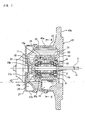
- a supercharger of the present invention comprising a housing having a cooling water jacket provided therein, and a turbine shaft supported in a center hole in a center portion of the housing through a rolling bearing, a turbine being mounted on one end portion of the turbine shaft and disposed exteriorly of the housing in an axial direction; wherein lubricating oil for the rolling bearing exists only within the housing; and the cooling water jacket is provided within a body portion of the housing over a region from one axial end portion of the body portion to the other axial end portion thereof.
- the lubricating oil for the rolling bearing exists only within the housing, and therefore the contamination of the lubricating oil by factors outside the supercharger such as carbon sludge developing in an engine as in the conventional structure can be prevented. Therefore, the performance of the rolling bearing can be prevented from being lowered by the lubricating oil. And besides, any construction for receiving lubricating oil from the exterior is not needed, and therefore the structure is simplified. Further, any passage for receiving the lubricating oil from the exterior does not need to be provided within the body portion of the housing. Therefore, the cooling water jacket can be provided within the body portion of the housing over the wide range from the one axial end portion to the other axial end portion. A cooling effect by this cooling water jacket can be enhanced, and the rolling bearing can be cooled over the wide range in the axial direction of the housing.
- a supercharger comprising a housing having a cooling water jacket provided therein, and a turbine shaft supported in a center hole in a center portion of the housing through a rolling bearing, a turbine being mounted on one end portion of the turbine shaft and disposed exteriorly of the housing in an axial direction; wherein the cooling water jacket comprises a passage for flowing a coolant at least more than one round around the center hole in a circumferential direction.
- the supply means may comprise a blade member for producing an air flow within the center hole in accordance with the rotation of the turbine shaft so as to render a pressure within the center hole negative relative to a pressure within the tank portion, and a lubricant passage leading from the tank portion to the center hole so that the lubricating oil can be drawn up from the tank potion by the negative pressure to flow to the center hole via the lubricant passage.
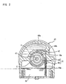
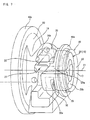
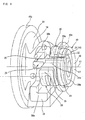
- the passage 16 of Figs. 6 and 7 the first and second passage portions 29 and 30 are juxtaposed, and in the passage 16 of Fig. 8 , the first and second passage portions 29 and 30 are juxtaposed, and the second and third passages 30 and 38 are juxtaposed. Therefore, the passage 16 can be arranged densely within the housing 40, and the cooling effect can be enhanced. Furthermore, the passage is formed in the circumferential direction, and therefore the rolling bearings 10a and 10b can be cooled over the entire periphery thereof, and the rolling bearings 10a and 10b can be cooled uniformly over the entire periphery thereof. Therefore, the temperature of each of the bearings 10a and 10b is prevented from becoming high at a localized portion thereof.
- the coolant is cooled at the coolant supply source (not shown) provided exteriorly of the housing 40, and the first passage portion 29 through which the supplied coolant first passes is disposed close to the turbine 42, and the second passage portion 30 (and the third passage portion 38) is disposed close to the compressor (not shown). Therefore, the turbine-side portion (42) within the housing 40 where the temperature becomes higher can be efficiently cooled. Furthermore, in Fig. 6 , the annular portion 29b of the first passage portion 29 has the generally annular portion 33 disposed at the one end portion 49 of the body portion 42a and projecting radially inwardly beyond the inner peripheral surface 43a of the center hole 43. Within the body portion 40a, this annular portion 33 is disposed between the turbine 42 and the rolling bearing 10a.
- the intermediate ring 2 includes a larger-diameter ring portion 7 of an annular shape, a smaller-diameter ring portion 6 of an annular shape, and an inclined ring portion 15 of an annular shape disposed between and interconnecting the larger-diameter and smaller-diameter ring portions 7 and 6.
- a diameter of an outer peripheral surface of the smaller-diameter ring portion 6 is smaller than a diameter of an outer peripheral surface of the larger-diameter ring portion 7.
- the inclined ring portion 15 extends linearly in inclined relation to the axis C.
- the larger-diameter ring portion 7 is disposed radially outwardly of the inner ring 1 with the row of first rolling elements 4 interposed therebetween.
- a diameter D3 of a pitch circle of the second rolling elements 5 contacting the fourth raceway 22 is larger than a diameter D4 of a pitch circle of the first rolling elements 4 contacting the third raceway 21. Therefore, the row of first rolling elements 4 and the row of second rolling elements 5 can be arranged close to each other in the axial direction with the inclined ring portion 15 interposed therebetween, and the axial dimension of the rolling bearing 10 can be reduced.
- the diameter of the pitch circle means a diameter of a circle passing through the centers of the row of balls.
- the fourth raceway 22 is formed on the outer peripheral surface of the boundary portion between the smaller-diameter ring portion 6 (smaller in diameter than the larger-diameter ring portion 7) and the inclined ring portion 15.
- the second rolling elements 5 contacting the fourth raceway 22 formed at the boundary portion between the smaller-diameter ring portion 6 and the inclined ring portion 5) are disposed at the radially inward position, and therefore the radial dimension of the rolling bearing 10 can be reduced.
- the outer diameter of the outer ring 3 can be reduced. Therefore, the inner diameter of the center hole 43 of the housing 40 (in which the rolling bearings 10a and 10b (see Fig. 1 ) are fixedly received) can be reduced. As a result, the capacity of the cooling water jacket 26 can be increased.
- a raceway is formed only on an inner periphery of a larger-diameter ring portion 57 of an intermediate ring 52 indicated in dots-and-dash lines, and also a raceway is formed only on an outer periphery of a smaller-diameter ring portion 56, the distance Q between a median plane of a row of rolling elements 54 and a median plane of a row of rolling elements 55 contacting the respective raceways is increased, and the overall axial length of the rolling bearing is increased.
- part of the third raceway 21 and part of the fourth raceway 22 are formed respectively on the inner and outer peripheral surfaces of the inclined ring portion 15 as indicated in solid lines in Fig.
- the distance P between a median plane of the row of rolling elements 4 and a median plane of the row of rolling elements 5 respectively contacting the third and fourth raceways 21 and 22 can be made smaller than the distance Q (P ⁇ Q). Namely, the row of rolling elements 4 and the row of rolling elements 5 can be disposed closer to each other, and therefore the axial dimension of the rolling bearing can be reduced.
- part of the third raceway 21 and part of the fourth raceway 22 are formed respectively on the inner and outer peripheral surfaces of the inclined ring portion 15, and the pitch circle diameter D3 of the second rolling elements 5 contacting the fourth raceway 22 is larger than the pitch circle diameter D4 of the first rolling elements 4 contacting the third raceway 21, and therefore the row of first rolling elements 4 and the row of second rolling elements 5 can be disposed close to each other in the direction of the axis C. Therefore, the dimension of the rolling bearing 10 in the direction of the axis C can be reduced. Therefore, a space for receiving the rolling bearing 10 can be reduced in the axial direction, and other parts can be provided adjacent to the rolling bearing.
- a raceway surface 22a of the fourth raceway 22 is disposed radially inwardly of a raceway surface 21a of the third raceway 21, and therefore the row of second rolling elements 5 contacting the fourth raceway 22 are disposed closer to the axis C in the radial direction, and therefore the radial dimension of the rolling bearing can be further reduced.
- the rolling bearing 10 of the invention is of such a type that at least one intermediate ring 2 is interposed between the inner and outer rings 1 and 3, and the plurality of rolling elements are rollably interposed between the opposed raceways of the inner and intermediate rings, and the plurality of rolling elements are rollably interposed between the opposed raceways of the intermediate and outer rings.
- Two intermediate rings 2a and 2b may be interposed between the inner and outer rings 1 and 3 as shown in Fig. 4 .
- the inner ring 1, the first intermediate ring 2a, the second intermediate ring 2b and the outer ring 3 are arranged in this order in the axial direction, and are offset from one another in the axial direction.
- a row of first rolling elements 45 are rollably interposed between the inner ring 1 and the first intermediate ring 2a, and a row of second rolling elements 46 are rollably interposed between the first intermediate ring 2a and the second intermediate ring 2b, and a row of third rolling elements 47 are rollably interposed between the second intermediate ring 2b and the outer ring 3.
- a third raceway 21 is formed at a boundary portion between an inner peripheral surface of the larger-diameter ring portion 7 and an inner peripheral surface of the inclined ring portion 15, and a fourth raceway 22 is formed at a boundary portion between an outer peripheral surface of the smaller-diameter ring portion 6 and an outer peripheral surface of the inclined ring portion 15.
- the rolling bearing 10 of the invention its component parts can be made of known materials, and particularly when the balls (rolling elements) and the intermediate ring are made of lightweight ceramics materials, there is achieved the structure capable of supporting the shaft rotating at still higher speed.
- the overall number of revolutions is distributed to the multi-stage bearing portions, so that the number of revolutions at each bearing portion is reduced, and therefore the rotation resistance at each bearing portion is reduced. Therefore, the rolling bearing 10 can be formed into a low torque structure as a whole. Therefore, in the turbocharger employing such rolling bearings 10, the rotation torque is reduced at the rolling bearings 10, and therefore a rotation response is enhanced, and a turbo lag can be suppressed.
Landscapes
- Engineering & Computer Science (AREA)
- General Engineering & Computer Science (AREA)
- Mechanical Engineering (AREA)
- Chemical & Material Sciences (AREA)
- Combustion & Propulsion (AREA)
- Supercharger (AREA)
Applications Claiming Priority (3)
| Application Number | Priority Date | Filing Date | Title |
|---|---|---|---|
| JP2006087299 | 2006-03-28 | ||
| JP2006268920A JP4797920B2 (ja) | 2006-03-28 | 2006-09-29 | 過給機 |
| PCT/JP2007/056440 WO2007116754A1 (ja) | 2006-03-28 | 2007-03-27 | 過給機 |
Publications (3)
| Publication Number | Publication Date |
|---|---|
| EP2000646A2 EP2000646A2 (de) | 2008-12-10 |
| EP2000646A9 true EP2000646A9 (de) | 2009-04-08 |
| EP2000646A4 EP2000646A4 (de) | 2015-03-25 |
Family
ID=38581051
Family Applications (1)
| Application Number | Title | Priority Date | Filing Date |
|---|---|---|---|
| EP07739878.2A Withdrawn EP2000646A4 (de) | 2006-03-28 | 2007-03-27 | Superlader |
Country Status (4)
| Country | Link |
|---|---|
| US (1) | US8181632B2 (de) |
| EP (1) | EP2000646A4 (de) |
| JP (1) | JP4797920B2 (de) |
| WO (1) | WO2007116754A1 (de) |
Families Citing this family (30)
| Publication number | Priority date | Publication date | Assignee | Title |
|---|---|---|---|---|
| JP2009167803A (ja) * | 2008-01-10 | 2009-07-30 | Jtekt Corp | 過給機 |
| KR100937901B1 (ko) * | 2008-04-21 | 2010-01-21 | 한국과학기술연구원 | 무급유 터보차저 어셈블리 |
| US20110014028A1 (en) * | 2009-07-09 | 2011-01-20 | Wood Ryan S | Compressor cooling for turbine engines |
| DE112011102810T5 (de) * | 2010-08-24 | 2013-05-29 | Borgwarner Inc. | Lagergehäuse eines Abgasturboladers |
| DE102011003907A1 (de) | 2011-02-10 | 2012-08-16 | Continental Automotive Gmbh | Abgasturbolader mit gekühltem Turbinengehäuse |
| EP2698504A1 (de) * | 2011-06-17 | 2014-02-19 | Aktiebolaget SKF | Turbolader, insbesondere für einen Verbrennungsmotor |
| JP5926094B2 (ja) * | 2012-03-30 | 2016-05-25 | 大豊工業株式会社 | ターボチャージャーの軸受ハウジング |
| US9234439B2 (en) | 2012-11-01 | 2016-01-12 | United Technologies Corporation | Gas turbine engine with bearing compartment wall cooling |
| EP2924261B1 (de) * | 2012-11-22 | 2019-09-25 | Mitsubishi Heavy Industries Engine & Turbocharger, Ltd. | Turbolader mit elektrischem motor und motorvorrichtung mit turbolader mit elektrischem motor |
| US9702266B2 (en) * | 2014-06-30 | 2017-07-11 | Honeywell International Inc. | Turbocharger turbine housing |
| US9915172B2 (en) | 2015-03-09 | 2018-03-13 | Caterpillar Inc. | Turbocharger with bearing piloted compressor wheel |
| US9879594B2 (en) | 2015-03-09 | 2018-01-30 | Caterpillar Inc. | Turbocharger turbine nozzle and containment structure |
| US9890788B2 (en) | 2015-03-09 | 2018-02-13 | Caterpillar Inc. | Turbocharger and method |
| US9822700B2 (en) | 2015-03-09 | 2017-11-21 | Caterpillar Inc. | Turbocharger with oil containment arrangement |
| US10066639B2 (en) | 2015-03-09 | 2018-09-04 | Caterpillar Inc. | Compressor assembly having a vaneless space |
| US9903225B2 (en) | 2015-03-09 | 2018-02-27 | Caterpillar Inc. | Turbocharger with low carbon steel shaft |
| US9683520B2 (en) | 2015-03-09 | 2017-06-20 | Caterpillar Inc. | Turbocharger and method |
| US10006341B2 (en) | 2015-03-09 | 2018-06-26 | Caterpillar Inc. | Compressor assembly having a diffuser ring with tabs |
| US9752536B2 (en) | 2015-03-09 | 2017-09-05 | Caterpillar Inc. | Turbocharger and method |
| US9810238B2 (en) | 2015-03-09 | 2017-11-07 | Caterpillar Inc. | Turbocharger with turbine shroud |
| US9777747B2 (en) | 2015-03-09 | 2017-10-03 | Caterpillar Inc. | Turbocharger with dual-use mounting holes |
| US9732633B2 (en) | 2015-03-09 | 2017-08-15 | Caterpillar Inc. | Turbocharger turbine assembly |
| US9650913B2 (en) | 2015-03-09 | 2017-05-16 | Caterpillar Inc. | Turbocharger turbine containment structure |
| US9739238B2 (en) | 2015-03-09 | 2017-08-22 | Caterpillar Inc. | Turbocharger and method |
| US9638138B2 (en) | 2015-03-09 | 2017-05-02 | Caterpillar Inc. | Turbocharger and method |
| DE102017219029A1 (de) * | 2017-10-25 | 2019-04-25 | Zf Friedrichshafen Ag | Prüfeinheit für einen Kupplungsprüfstand sowie Kupplungsprüfstand mit der Prüfeinheit |
| US11181007B1 (en) * | 2019-02-28 | 2021-11-23 | Florida Turbine Technologies, Inc. | Gas turbine engine bearing with fuel lubrication and cooling |
| JP7452711B2 (ja) * | 2021-02-10 | 2024-03-19 | 株式会社Ihi | 電動過給機 |
| DE102021124357A1 (de) * | 2021-09-21 | 2023-03-23 | MTU Aero Engines AG | Hitzeschutzelement für eine Lagerkammer einer Gasturbine |
| CN116241339A (zh) * | 2023-01-18 | 2023-06-09 | 天津北方天力增压技术有限公司 | 一种高可靠性的涡轮增压器转子系统 |
Family Cites Families (14)
| Publication number | Priority date | Publication date | Assignee | Title |
|---|---|---|---|---|
| US4179247A (en) * | 1977-01-14 | 1979-12-18 | Wrr Industries, Inc. | Turbocharger having variable area turbine nozzles |
| JPS59141721A (ja) * | 1983-02-01 | 1984-08-14 | Ishikawajima Harima Heavy Ind Co Ltd | 小形過給機 |
| JPH0540275Y2 (de) * | 1988-05-17 | 1993-10-13 | ||
| JPH0333431A (ja) * | 1989-06-30 | 1991-02-13 | Hitachi Ltd | 内燃機関用過給機 |
| JPH04183933A (ja) * | 1990-11-20 | 1992-06-30 | Tochigi Fuji Ind Co Ltd | 過給機 |
| JP3084841B2 (ja) * | 1991-09-18 | 2000-09-04 | 石川島播磨重工業株式会社 | 過給機の水冷軸受ハウジング構造 |
| JP2924363B2 (ja) * | 1991-09-18 | 1999-07-26 | 石川島播磨重工業株式会社 | 過給機の水冷軸受ハウジング構造 |
| US5161960A (en) * | 1991-11-12 | 1992-11-10 | Allied-Signal Inc. | Turbocharger with liquid cooled housing |
| DE4330380A1 (de) * | 1993-09-08 | 1995-03-09 | Abb Management Ag | Abgasturbolader mit mehrteiligem Lagergehäuse |
| JPH07208191A (ja) * | 1994-01-10 | 1995-08-08 | Ishikawajima Harima Heavy Ind Co Ltd | ターボチャージャー |
| JPH1019045A (ja) | 1996-07-03 | 1998-01-20 | Koyo Seiko Co Ltd | 深溝型玉軸受およびそれを用いた過給機 |
| JP2000130176A (ja) * | 1998-10-30 | 2000-05-09 | Isuzu Motors Ltd | 発電・電動機を備えたターボチャージャ |
| JP4183933B2 (ja) | 2001-07-25 | 2008-11-19 | 株式会社 東京ウエルズ | ワーク供給装置 |
| JP2008082298A (ja) * | 2006-09-28 | 2008-04-10 | Jtekt Corp | 過給機 |
-
2006
- 2006-09-29 JP JP2006268920A patent/JP4797920B2/ja not_active Expired - Fee Related
-
2007
- 2007-03-27 US US12/225,666 patent/US8181632B2/en not_active Expired - Fee Related
- 2007-03-27 WO PCT/JP2007/056440 patent/WO2007116754A1/ja not_active Ceased
- 2007-03-27 EP EP07739878.2A patent/EP2000646A4/de not_active Withdrawn
Also Published As
| Publication number | Publication date |
|---|---|
| US8181632B2 (en) | 2012-05-22 |
| WO2007116754A1 (ja) | 2007-10-18 |
| EP2000646A4 (de) | 2015-03-25 |
| US20090101087A1 (en) | 2009-04-23 |
| JP2007292041A (ja) | 2007-11-08 |
| EP2000646A2 (de) | 2008-12-10 |
| JP4797920B2 (ja) | 2011-10-19 |
Similar Documents
| Publication | Publication Date | Title |
|---|---|---|
| US8181632B2 (en) | Supercharger | |
| US20090081040A1 (en) | Rolling bearing device and turbocharger incorporating same | |
| US5522667A (en) | Ball bearing for turbocharger | |
| CN101415920A (zh) | 增压器 | |
| CN103842674B (zh) | 动态润滑的轴承和动态润滑轴承的方法 | |
| US20120189235A1 (en) | Bearing race for a rolling-element bearing | |
| EP1580028A2 (de) | Kegelrollenlager | |
| EP2711573B1 (de) | Lagervorrichtung | |
| CN112196969A (zh) | 油管罩及包括该罩的用于飞行器涡轮机的机械齿轮减速器 | |
| EP1905980A2 (de) | Auflader | |
| US20070003178A1 (en) | Cylindrical roller bearing and retainer for cylindrical roller bearing | |
| EP2042690B1 (de) | Turbolader | |
| JP2009287678A (ja) | ころ軸受および軸受構造物 | |
| JP2024101198A (ja) | 玉軸受及び軸受装置 | |
| JP2009203846A (ja) | ターボチャージャ用軸受装置 | |
| JP2010007788A5 (de) | ||
| US20090067768A1 (en) | Rolling Bearing and Supercharger Using Same | |
| JP7760958B2 (ja) | 転がり軸受潤滑構造 | |
| JP2014126083A (ja) | 玉軸受ユニット | |
| JP6539507B2 (ja) | 軸受ユニット | |
| JP6074966B2 (ja) | 軸受装置 | |
| JP6307883B2 (ja) | 転がり軸受 | |
| US12449002B2 (en) | Tapered roller bearing | |
| EP3564494B1 (de) | Turboladerlagergehäuse mit nichtkreisförmigen lagerbohrungen | |
| EP2535608A1 (de) | Wälzlager, insbesondere für einen Turbolader |
Legal Events
| Date | Code | Title | Description |
|---|---|---|---|
| PUAI | Public reference made under article 153(3) epc to a published international application that has entered the european phase |
Free format text: ORIGINAL CODE: 0009012 |
|
| 17P | Request for examination filed |
Effective date: 20080926 |
|
| AK | Designated contracting states |
Kind code of ref document: A2 Designated state(s): DE FR GB |
|
| PUAB | Information related to the publication of an a document modified or deleted |
Free format text: ORIGINAL CODE: 0009199EPPU |
|
| DAX | Request for extension of the european patent (deleted) | ||
| RBV | Designated contracting states (corrected) |
Designated state(s): DE FR GB |
|
| A4 | Supplementary search report drawn up and despatched |
Effective date: 20150225 |
|
| RIC1 | Information provided on ipc code assigned before grant |
Ipc: F02B 39/00 20060101ALI20150218BHEP Ipc: F02B 39/14 20060101AFI20150218BHEP Ipc: F16C 33/66 20060101ALI20150218BHEP Ipc: F01D 25/14 20060101ALI20150218BHEP |
|
| STAA | Information on the status of an ep patent application or granted ep patent |
Free format text: STATUS: THE APPLICATION IS DEEMED TO BE WITHDRAWN |
|
| 18D | Application deemed to be withdrawn |
Effective date: 20171003 |