EP2000637B1 - Schalldämpfer - Google Patents
Schalldämpfer Download PDFInfo
- Publication number
- EP2000637B1 EP2000637B1 EP08157032A EP08157032A EP2000637B1 EP 2000637 B1 EP2000637 B1 EP 2000637B1 EP 08157032 A EP08157032 A EP 08157032A EP 08157032 A EP08157032 A EP 08157032A EP 2000637 B1 EP2000637 B1 EP 2000637B1
- Authority
- EP
- European Patent Office
- Prior art keywords
- pipe
- outlet
- inlet
- housing
- inlet pipe
- Prior art date
- Legal status (The legal status is an assumption and is not a legal conclusion. Google has not performed a legal analysis and makes no representation as to the accuracy of the status listed.)
- Revoked
Links
Images
Classifications
-
- F—MECHANICAL ENGINEERING; LIGHTING; HEATING; WEAPONS; BLASTING
- F01—MACHINES OR ENGINES IN GENERAL; ENGINE PLANTS IN GENERAL; STEAM ENGINES
- F01N—GAS-FLOW SILENCERS OR EXHAUST APPARATUS FOR MACHINES OR ENGINES IN GENERAL; GAS-FLOW SILENCERS OR EXHAUST APPARATUS FOR INTERNAL-COMBUSTION ENGINES
- F01N1/00—Silencing apparatus characterised by method of silencing
- F01N1/003—Silencing apparatus characterised by method of silencing by using dead chambers communicating with exhaust gas flow passages
-
- F—MECHANICAL ENGINEERING; LIGHTING; HEATING; WEAPONS; BLASTING
- F01—MACHINES OR ENGINES IN GENERAL; ENGINE PLANTS IN GENERAL; STEAM ENGINES
- F01N—GAS-FLOW SILENCERS OR EXHAUST APPARATUS FOR MACHINES OR ENGINES IN GENERAL; GAS-FLOW SILENCERS OR EXHAUST APPARATUS FOR INTERNAL-COMBUSTION ENGINES
- F01N1/00—Silencing apparatus characterised by method of silencing
- F01N1/08—Silencing apparatus characterised by method of silencing by reducing exhaust energy by throttling or whirling
- F01N1/084—Silencing apparatus characterised by method of silencing by reducing exhaust energy by throttling or whirling the exhaust gases flowing through the silencer two or more times longitudinally in opposite directions, e.g. using parallel or concentric tubes
-
- F—MECHANICAL ENGINEERING; LIGHTING; HEATING; WEAPONS; BLASTING
- F01—MACHINES OR ENGINES IN GENERAL; ENGINE PLANTS IN GENERAL; STEAM ENGINES
- F01N—GAS-FLOW SILENCERS OR EXHAUST APPARATUS FOR MACHINES OR ENGINES IN GENERAL; GAS-FLOW SILENCERS OR EXHAUST APPARATUS FOR INTERNAL-COMBUSTION ENGINES
- F01N1/00—Silencing apparatus characterised by method of silencing
- F01N1/16—Silencing apparatus characterised by method of silencing by using movable parts
- F01N1/165—Silencing apparatus characterised by method of silencing by using movable parts for adjusting flow area
-
- F—MECHANICAL ENGINEERING; LIGHTING; HEATING; WEAPONS; BLASTING
- F01—MACHINES OR ENGINES IN GENERAL; ENGINE PLANTS IN GENERAL; STEAM ENGINES
- F01N—GAS-FLOW SILENCERS OR EXHAUST APPARATUS FOR MACHINES OR ENGINES IN GENERAL; GAS-FLOW SILENCERS OR EXHAUST APPARATUS FOR INTERNAL-COMBUSTION ENGINES
- F01N1/00—Silencing apparatus characterised by method of silencing
- F01N1/08—Silencing apparatus characterised by method of silencing by reducing exhaust energy by throttling or whirling
- F01N1/10—Silencing apparatus characterised by method of silencing by reducing exhaust energy by throttling or whirling in combination with sound-absorbing materials
Definitions
- the present invention relates to a silencer for airborne sound conducting pipe system, in particular for an exhaust system, preferably in an internal combustion engine.
- mufflers are used to avoid unwanted noise emission into the environment.
- silencers which work according to the absorption structure or the reflection construction or combinations thereof. In this construction results in respect of the attenuated frequencies in a substantially constant damping effect.
- the spectrum of disturbing sound varies relatively strong, since it is speed and load-dependent. For example, significantly dominated engine orders have excessive sound pressure levels.
- mufflers may include at least one flap with which a gas flow path in the muffler is controllable.
- active systems in which an external control for actuating an actuator driving the respective flap is required
- passive systems are known in which the respective flap is actuated by the gas flow. With the help of such a flap, the damping effect and the counter-pressure behavior of the muffler can be influenced.
- active systems are relatively expensive in terms of manufacturing costs due to the required additional active control components, such as control unit, vacuum unit, vacuum line, switching valve.
- a silencer with an active system In the DE 19540716 is proposed a silencer with an active system. Passive systems are less expensive than active systems, but may be more or less complicated and / or develop only a comparatively low acoustic effect and / or produce a comparatively high counterpressure and / or have a comparatively large volume of construction.
- the present invention is concerned with the problem of providing an improved embodiment for a silencer, which is characterized in particular by the fact that it is comparatively inexpensive and / or comparatively compact and / or has a comparatively high acoustic effect with a favorable counterpressure behavior.
- the present invention is based on the general idea, in a silencer whose inlet pipe is equipped with a passive operating switching element, branch off a bypass pipe from the inlet pipe upstream of the switching element and form or arrange the pipe system in the housing so that the interior of the housing, ie substantially the entire silencer volume is acoustically effective when the switching element is open and closed.
- the switching element remains closed and the gas flow and the airborne sound transported therein are - except for unavoidable leaks at the flap - passed exclusively through the bypass pipe. This makes it possible to achieve a comparatively high acoustic damping effect.
- the respective switching element is open, so that the gas flow and the airborne sound transported therein largely passes over the controlled by the switching element end portion of the inlet pipe into the interior of the muffler.
- the exhaust backpressure is comparatively low.
- the acoustic effect of the muffler can be designed in this case so that it can still be accepted for the particular application of the muffler. Due to the proposed construction of the muffler has a relatively simple and suitable for different applications and in so far universal structure. In particular, the Silencer by the one acoustically undivided interior inexpensive to produce.
- the proposed muffler is characterized by a high acoustic damping effect at low gas flow, as they occur, for example, at low speeds and operating loads of an internal combustion engine.
- the proposed muffler is characterized by a comparatively low flow noise and by a relatively low back pressure, which is achieved in particular by the use of the acoustically undivided interior.
- the installation space is lower than in conventional mufflers, which have comparable acoustic properties without switching elements and / or a comparable low back pressure.
- the outlet of the inlet pipe, the outlet of the bypass pipe and the respective inlet of the at least one outlet pipe may be arranged acoustically in the same space or volume.
- the muffler may include at least one absorption sleeve, which in at least an outlet tube encloses an axial section extending in the interior and is acoustically coupled to the interior of the respective outlet tube.
- at least one absorption chamber may be formed in the housing, which is acoustically coupled to the rest of the interior.
- the respective absorption sleeve or the respective absorption chamber are arranged in a shunt and thus influence neither the gas flow nor the sound propagation, neither with the door open nor with the door closed. They bring about an intensive damping of high-frequency flow noise, which can occur in particular when flowing around the respective switching element.
- a muffler 1 comprises a housing 2 which encloses an interior space 3.
- the muffler 1 is suitable, for example, for damping airborne noise in a pipe system that carries airborne sound or in which airborne sound can propagate.
- a pipe system that carries airborne sound or in which airborne sound can propagate.
- Such pipe systems can be found for example in turbo groups of power plants and in internal combustion engines, namely in a fresh gas system or in an exhaust system.
- Preference is given here to the use of the muffler 1 in an exhaust system of an internal combustion engine, which may be arranged in particular in a motor vehicle.
- the silencer 1 further comprises an inlet pipe 4, which has at least one outlet 5 in the interior 3, which is preferably axially open.
- inlet pipe 4 which has at least one outlet 5 in the interior 3, which is preferably axially open.
- more than one inlet pipe 4 may be provided.
- the embodiment shown here is preferred with only a single inlet pipe 4.
- From the inlet pipe 4 branches off a bypass pipe 6, within the housing 2 and preferably in the interior 3.
- the bypass pipe 6 has in the interior 3 at least one outlet 7, which preferably axially open.
- from the respective inlet pipe 4 or branch off from the inlet pipes 4 also a plurality of bypass pipes 6.
- the embodiment shown here in which only a single bypass tube 6 is provided is preferred.
- the bypass pipe 6 is substantially perpendicular from the inlet pipe 4; other angles are possible.
- a switching element 8 is arranged, which is actuated as a function of the gas flow, that is, as a function of the gas mass flow.
- the switching element 8 is a flap, which is driven by gravity and / or spring-loaded in a closed position shown by a solid line and which can be driven by the flow forces more or less to open.
- an open position is shown with a broken line.
- the passively operating switching element 8 opens more or less, whereby the gas flow and thus the airborne sound more or less controlled by the switching element 8, downstream of the bypass tube 6 end portion of the inlet tube 4 and thus flows through the outlet 5 of the inlet pipe 4. From a certain size of the gas flow or from a certain gas mass flow, the gas flow and thus also the entrained airborne sound largely enters the interior 3 through the outlet 5 of the inlet pipe 4.
- a corresponding flow path or airborne sound propagation path is indicated in the figures by broken arrows.
- Fig. 1 shows an embodiment in which the switching element 8 is arranged directly at the outlet 5 of the inlet pipe 4.
- the switching element 8 can be particularly easily attached to the inlet pipe 4 in this construction.
- Fig.2 By way of example, an embodiment in which the switching element 8 is installed in the inlet pipe 4, that is, is located downstream of the associated outlet 5. This design can for example offer space advantages.
- the silencer 1 also has at least one outlet pipe 9, which has at least one inlet 10 in the interior 3, which is preferably axially open.
- outlet pipe 9 which has at least one inlet 10 in the interior 3, which is preferably axially open.
- only a single outlet pipe 9 is shown.
- designs are conceivable in which more than one outlet pipe 9 is provided.
- the muffler 1 is characterized in particular by the fact that the interior 3, in which the outlet 5 of Inlet pipe 4, the outlet 7 of the bypass pipe 6 and the inlet 10 of the outlet pipe 9 are acoustically undivided.
- the said openings or pipe ends 5, 7, 10 are acoustically in the same space, namely in the interior 3 or in the same acoustic volume, namely in the volume of the interior 3.
- the impact of airborne sound volume of the interior 3 is independent of the operating state of the switching element 8 always the same size.
- the airborne sound can propagate in the entire acoustic volume of the interior 3 both with the switching element 8 open and closed. This design leads to a relatively small space requirement of the muffler 1.
- the bypass pipe 6 is dimensioned such that a flow of the muffler 1 adjusts from a predetermined gas flow, in which the gas flow and thus the entrained airborne sound passes mainly through the outlet 5 of the inlet pipe 4 into the interior 3.
- this is a cross section 11 or - in a circular cross section - a diameter 11 of the bypass tube 6 smaller than a cross section 12 or - in a circular cross section - a diameter 12 of the inlet tube 4.
- an axial length 13 of the bypass tube 6 at least equal be as the diameter 12 of the inlet pipe 4. In the examples shown, the axial length 13 of the bypass pipe 6 is greater than the diameter 12 of the inlet pipe 4th
- the outlet pipe 9 is equipped inside the housing 2 with an absorption sleeve 14. This encloses in the interior 3 an axial section of the outlet pipe 9.
- the axial section of the outlet pipe 9 enclosed by the absorption sleeve 14 has a perforated wall 15, whereby the absorption sleeve 14 or its annular space 16 is acoustically coupled to the interior of the outlet pipe 9.
- the annular space 16 may be filled or stuffed with a sound-absorbing substance 17, in particular a porous absorption material.
- the muffler 1 have at least one absorption chamber 18 which is arranged in the housing 2.
- the absorption chamber 18, which in particular can be filled again with a sound-absorbing substance 17, is bounded here by a perforated wall 19 and by the housing 2.
- the absorption chamber 18 is formed in the region of a bottom 20 of the housing 2, so that the respective housing bottom 20 with adjoining sections of a housing jacket 21 delimits the respective absorption chamber 18.
- this or another absorption chamber along the (entire) housing shell 21 may be arranged so that the housing shell 21 and in particular edge regions of the housing bottoms 20 limit the absorption chamber.
- the at least one perforated wall 19 used to confine the absorption chamber 18 is positioned so as to be between the respective absorption chamber 18 and the Outlet 5 of the inlet pipe 4, the outlet 7 of the bypass pipe 6 and the inlet 10 of the outlet pipe 9 is located.
- the absorption chamber 18 is thus arranged in shunt and is not flowed through. This also applies to the absorption sleeve 14.
- the housing 1 may be stiffened with at least one perforated intermediate bottom 22.
- the end portions of the inlet pipe 4 and the at least one outlet pipe 9 may be supported.
- the outlet 5 of the inlet tube 4 and the inlet 10 of the outlet tube 9 are arranged and / or aligned relative to one another in the interior 3 such that a gas flow in the interior 3 has to reverse its flow direction twice by approximately 180 ° in order to exit from the outlet 5 of the inlet pipe 4 to the inlet 10 of the outlet pipe 9 to arrive.
- outlet 7 of the bypass tube 6 and the inlet 10 of the outlet tube 9 in the interior 3 are arranged or oriented relative to each other so that the gas flow in the interior 3 is not their flow direction or - as here - only once by about 90 ° or less to change from the outlet 7 of the bypass pipe 6 to the inlet 10 of the outlet pipe 9.
- the selected arrangements of the respective pipe ends or openings 5, 7, 10 contribute to the fact that in the respective operating state, thus depending on the gas mass flow, sets the desired effective damping or the desired comparatively low back pressure.
- the silencer 1 comprises an assembly 23 which forms a unit which can be pre-assembled separately or independently with respect to the other components of the silencer 1.
- This assembly 23 includes an end portion 24 of the inlet pipe 4, which includes the bypass pipe 6 and the switching element 8.
- This assembly 23 is designed so that it can be relatively easily attached to a terminal end 25 of the remaining inlet pipe 4. For example, a plug connection is conceivable here.
Landscapes
- Engineering & Computer Science (AREA)
- Chemical & Material Sciences (AREA)
- Combustion & Propulsion (AREA)
- Mechanical Engineering (AREA)
- General Engineering & Computer Science (AREA)
- Exhaust Silencers (AREA)
Description
- Die vorliegende Erfindung betrifft einen Schalldämpfer für ein Luftschall führendes Rohrsystem, insbesondere für eine Abgasanlage, vorzugsweise in einer Brennkraftmaschine.
- Bei Rohrsystemen, in denen sich Luftschall ausbreiten kann, wie zum Beispiel in Kanälen von Lüftungsanlagen oder Klimaanlagen, in Zu- und Ableitungen von Kompressoren oder Verdichtern, in Frischgasanlagen sowie in Abgasanlagen von Brennkraftmaschinen, werden zur Vermeidung einer unerwünschten Schallemission in die Umgebung Schalldämpfer verwendet. Bekannt sind beispielsweise Schalldämpfer, die nach der Absorptionsbauweise oder nach der Reflexionsbauweise oder Kombinationen daraus arbeiten. Bei dieser Bauweise ergibt sich hinsichtlich der gedämpften Frequenzen eine im wesentliche konstante Dämpfungswirkung. Bei Brennkraftmaschinen variiert jedoch das Spektrum des störenden Schalls relativ stark, da es drehzahl- und lastabhängig ist. Beispielsweise existieren bei dominierenden Motorordnungen deutlich überhöhte Schalldruckpegel.
- Ferner können Schalldämpfer zumindest eine Klappe enthalten, mit denen ein Gasströmungspfad im Schalldämpfer steuerbar ist. Hier sind aktive Systeme, bei denen eine externe Steuerung zur Betätigung eines die jeweilige Klappe antreibenden Stellantriebs erforderlich ist, sowie passive Systeme bekannt, bei denen die jeweilige Klappe durch die Gasströmung betätigt wird. Mit Hilfe einer derartigen Klappe kann die Dämpfungswirkung sowie das Gegendruckverhalten des Schalldämpfers beeinflusst werden. Aktive Systeme sind jedoch hinsichtlich der Herstellungskosten aufgrund der erforderlichen zusätzlichen aktiven Steuerungskomponenten, wie zum Beispiel Steuergerät, Unterdruckdose, Unterdruckleitung, Schaltventil, vergleichsweise aufwendig. In der
DE 19540716 ist ein Schalldämpfer mit einem aktiven System vorgeschlagen. Passive Systeme sind zwar preiswerter als aktive Systeme, können jedoch mehr oder weniger kompliziert aufgebaut sein und/oder nur eine vergleichsweise geringe akustische Wirkung entfalten und/oder einen vergleichsweise hohen Gegendruck erzeugen und/oder ein vergleichsweise großes Bauvolumen besitzen. - Die vorliegende Erfindung beschäftigt sich mit dem Problem, für einen Schalldämpfer eine verbesserte Ausführungsform anzugeben, die sich insbesondere dadurch auszeichnet, dass sie vergleichsweise preiswert und/oder vergleichsweise kompakt baut und/oder eine vergleichsweise hohe akustische Wirkung bei einem günstigen Gegendruckverhalten aufweist.
- Dieses Problem wird erfindungsgemäß durch den Gegenstand des unabhängigen Anspruchs gelöst. Vorteilhafte Ausführungsformen sind Gegenstand der abhängigen Ansprüche.
- Die vorliegende Erfindung beruht auf dem allgemeinen Gedanken, bei einem Schalldämpfer, dessen Einlassrohr mit einem passiv arbeitenden Schaltelement ausgestattet ist, vom Einlassrohr stromauf des Schaltelements ein Bypassrohr abzuzweigen und das Rohrsystem im Gehäuse so auszubilden beziehungsweise anzuordnen, dass der Innenraum des Gehäuses, also im wesentlichen das gesamte Schalldämpfervolumen bei geöffnetem und bei geschlossenem Schaltelement akustisch wirksam ist. Bei geringen Massenströmen, wie sie beispielsweise im Leerlauf einer Brennkraftmaschine auftreten, bleibt das Schaltelement geschlossen und die Gasströmung sowie der darin transportierte Luftschall werden - abgesehen von unvermeidlichen Leckagen an der Klappe - ausschließlich über das Bypassrohr geleitet. Hierdurch lässt sich eine vergleichsweise hohe akustische Dämpfungswirkung erzielen. Bei hohen Massenströmen, wie sie beispielsweise bei Volllast einer Brennkraftmaschine auftreten, ist das jeweilige Schaltelement geöffnet, so dass die Gasströmung und der darin transportierte Luftschall weitgehend über den vom Schaltelement gesteuerten Endbereich des Einlassrohres in den Innenraum des Schalldämpfers gelangt. In diesem Fall ist der Abgasgegendruck vergleichsweise gering. Die akustische Wirkung des Schalldämpfers kann für diesen Fall so ausgelegt werden, dass sie für den jeweiligen Anwendungsfall des Schalldämpfers noch akzeptiert werden kann. Durch die vorgeschlagene Bauweise besitzt der Schalldämpfer einen vergleichsweise einfachen und für unterschiedliche Anwendungsfälle geeigneten und insoweit universellen Aufbau. Insbesondere ist der Schalldämpfer durch den einen akustisch ungeteilten Innenraum preiswert herstellbar. Ferner zeichnet sich der vorgeschlagene Schalldämpfer durch eine hohe akustische Dämpfungswirkung bei kleiner Gasströmung aus, wie sie beispielsweise bei niedrigen Drehzahlen und Betriebslasten einer Brennkraftmaschine auftreten. Bei großen Gasströmungen, wie sie beispielsweise bei hohen Drehzahlen und Betriebslasten einer Brennkraftmaschine auftreten, zeichnet sich der vorgeschlagene Schalldämpfer durch ein vergleichsweise geringes Strömungsrauschen sowie durch einen vergleichsweise niedrigen Gegendruck aus, was insbesondere durch die Verwendung des akustisch ungeteilten Innenraums erreicht wird. Ferner ist beim vorgeschlagenen Schalldämpfer der Bauraum geringer als bei konventionellen Schalldämpfern, die vergleichbare akustische Eigenschaften ohne Schaltelemente und/oder einen vergleichbaren niedrigen Gegendruck besitzen.
- Entsprechend einer bevorzugten Ausführungsform können der Auslass des Einlassrohrs, der Auslass des Bypassrohrs und der jeweilige Einlass des wenigstens einen Auslassrohrs akustisch im gleichen Raum oder Volumen angeordnet sein. Hierdurch lässt sich auf vergleichsweise preiswerte Weise erreichen, dass das vom Luftschall beaufschlagte Volumen des Innenraums bei geöffnetem und geschlossenem Schaltelement gleich groß ist, was zum erwünschten akustisch ungeteilten Innenraum führt.
- Gemäß einer bevorzugten Ausführungsform kann der Schalldämpfer zumindest eine Absorptionshülse enthalten, die bei wenigstens einem Auslassrohr einen im Innenraum verlaufenden Axialabschnitt umhüllt und mit dem Inneren des jeweiligen Auslassrohrs akustisch gekoppelt ist. Zusätzlich oder alternativ kann im Gehäuse wenigstens eine Absorptionskammer ausgebildet sein, die akustisch mit dem übrigen Innenraum gekoppelt ist. Die jeweilige Absorptionshülse beziehungsweise die jeweilige Absorptionskammer sind im Nebenschluss angeordnet und beeinflussen somit weder die Gasströmung noch die Schallausbreitung, und zwar weder bei geöffneter noch bei geschlossener Klappe. Sie bewirken eine intensive Bedämpfung hochfrequenter Strömungsgeräusche, die insbesondere beim Umströmen des jeweiligen Schaltelements auftreten können.
- Weitere wichtige Merkmale und Vorteile der Erfindung ergeben sich aus den Unteransprüchen, aus den Zeichnungen und aus der zugehörigen Figurenbeschreibung anhand der Zeichnungen.
- Es versteht sich, dass die vorstehend genannten und die nachstehend noch zu erläuternden Merkmale nicht nur in der jeweils angegebenen Kombination, sondern auch in anderen Kombinationen oder in Alleinstellung verwendbar sind, ohne den Rahmen der vorliegenden Erfindung zu verlassen.
- Bevorzugte Ausführungsbeispiele der Erfindung sind in den Zeichnungen dargestellt und werden in der nachfolgenden Beschreibung näher erläutert, wobei sich gleiche Bezugszeichen auf gleiche oder ähnliche oder funktional gleiche Bauteile beziehen.
- Es zeigen, jeweils schematisch,
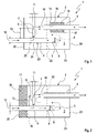
- Fig. 1
- eine stark vereinfachte, schaltplanartige Prinzipdarstellung eines Schalldämpfers im Schnitt,
- Fig. 2
- eine Ansicht wie in
Fig. 1 , jedoch bei einer anderen Ausführungsform. - Entsprechend den
Fig. 1 und 2 umfasst ein Schalldämpfer 1 ein Gehäuse 2, das einen Innenraum 3 umschließt. Der Schalldämpfer 1 eignet sich beispielsweise zur Bedämpfung von Luftschall in einem Rohrsystem, das Luftschall führt beziehungsweise in dem sich Luftschall ausbreiten kann. Derartige Rohrsysteme finden sich beispielsweise bei Turbogruppen von Kraftwerksanlagen sowie bei Brennkraftmaschinen, nämlich in einer Frischgasanlage oder in einer Abgasanlage. Bevorzugt ist hier die Verwendung des Schalldämpfers 1 in einer Abgasanlage einer Brennkraftmaschine, die insbesondere in einem Kraftfahrzeug angeordnet sein kann. - Der Schalldämpfer 1 umfasst ferner ein Einlassrohr 4, das im Innenraum 3 zumindest einen Auslass 5 besitzt, der bevorzugt axial offen ist. Grundsätzlich kann auch mehr als ein Einlassrohr 4 vorgesehen sein. Bevorzugt wird jedoch die hier gezeigte Ausführungsform mit nur einem einzigen Einlassrohr 4. Vom Einlassrohr 4 zweigt ein Bypassrohr 6 ab, und zwar innerhalb des Gehäuses 2 und bevorzugt im Innenraum 3. Das Bypassrohr 6 weist im Innenraum 3 zumindest einen Auslass 7 auf, der bevorzugt axial offen ist. Grundsätzlich können vom jeweiligen Einlassrohr 4 beziehungsweise von den Einlassrohren 4 auch mehrere Bypassrohre 6 abzweigen. Bevorzugt ist jedoch die hier gezeigte Ausführungsform, bei der nur ein einziges Bypassrohr 6 vorgesehen ist. Im Beispiel steht das Bypassrohr 6 im wesentlichen senkrecht vom Einlassrohr 4 ab; andere Winkel sind denkbar.
- An beziehungsweise im Einlassrohr 4 ist ein Schaltelement 8 angeordnet, das in Abhängigkeit der Gasströmung, also in Abhängigkeit des Gasmassenstroms betätigt wird. Im symbolisch dargestellten einfachsten Fall handelt es sich beim Schaltelement 8 um eine Klappe, die schwerkraftbedingt und/oder federbelastet in eine mit durchgezogener Linie dargestellte Schließstellung angetrieben ist und die durch die Strömungskräfte mehr oder weniger zum Öffnen antreibbar ist. In den Figuren ist eine Offenstellung mit unterbrochener Linie dargestellt. Bei vergleichsweise kleiner Gasströmung, also bei einem vergleichsweise niedrigen Gasmassenstrom bleibt das Schaltelement 8 im wesentlichen geschlossen, so das die Gasströmung im wesentlichen ausschließlich durch das Bypassrohr 6 in den Innenraum 3 gelangt. Der entsprechende Pfad führt die Gasströmung und somit den darin transportierten Luftschall und ist in den Figuren mit durchgezogenen Pfeilen symbolisiert. Bei einer vergleichsweise großen Gasströmung beziehungsweise bei relativ großen Gasmassenströmen öffnet das passiv arbeitende Schaltelement 8 mehr oder weniger, wodurch die Gasströmung und somit der Luftschall mehr oder weniger durch den durch das Schaltelement 8 gesteuerten, stromab des Bypassrohrs 6 liegenden Endabschnitt des Einlassrohrs 4 und somit durch den Auslass 5 des Einlassrohrs 4 strömt. Ab einer gewissen Größe der Gasströmung beziehungsweise ab einem gewissen Gasmassenstrom tritt der Gasstrom und somit auch der mitgeführte Luftschall größtenteils durch den Auslass 5 des Einlassrohrs 4 in den Innenraum 3 ein. Ein entsprechender Strömungspfad beziehungsweise Luftschallausbreitungspfad ist in den Figuren durch unterbrochene Pfeile angedeutet.
- Das jeweilige Schaltelement 8 ist stromab des Bypassrohrs 6 am oder im Einlassrohr 4 angeordnet.
Fig. 1 zeigt eine Ausführungsform, bei welcher das Schaltelement 8 unmittelbar am Auslass 5 des Einlassrohrs 4 angeordnet ist. Das Schaltelement 8 kann bei dieser Bauweise besonders einfach an das Einlassrohr 4 angebaut werden. Im Unterschied dazu zeigtFig.2 exemplarisch eine Ausführungsform, bei welcher das Schaltelement 8 in das Einlassrohr 4 eingebaut ist, sich also stromab des zugehörigen Auslasses 5 befindet. Diese Bauweise kann beispielsweise Bauraumvorteile bieten. - Der Schalldämpfer 1 weist außerdem zumindest ein Auslassrohr 9 auf, das im Innenraum 3 zumindest einen Einlass 10 besitzt, der bevorzugt axial offen ist. Im Beispiel ist nur ein einziges Auslassrohr 9 dargestellt. Ebenso sind Bauformen denkbar, bei denen mehr als ein Auslassrohr 9 vorgesehen ist.
- Der Schalldämpfer 1 charakterisiert sich nun insbesondere dadurch, dass der Innenraum 3, in dem sich der Auslass 5 des Einlassrohrs 4, der Auslass 7 des Bypassrohrs 6 sowie der Einlass 10 des Auslassrohrs 9 befinden, akustisch ungeteilt ist. Somit befinden sich die genannten Öffnungen oder Rohrenden 5, 7, 10 akustisch im gleichen Raum, nämlich im Innenraum 3 oder im gleichen akustischen Volumen, nämlich im Volumen des Innenraums 3. In der Folge ist das vom Luftschall beaufschlagte Volumen des Innenraums 3 unabhängig vom Betätigungszustand des Schaltelements 8 stets gleich groß. Der Luftschall kann sich sowohl bei geöffnetem als auch bei geschlossenem Schaltelement 8 im ganzen akustischen Volumen des Innenraums 3 ausbreiten. Diese Bauweise führt zu einem relativ geringen Bauraumbedarf des Schalldämpfers 1. Gleichzeitig vereinfacht sich der Aufbau, was die Herstellungskosten senkt. Das Bypassrohr 6 ist so dimensioniert, dass sich ab einem vorbestimmten Gasstrom eine Durchströmung des Schalldämpfers 1 einstellt, bei welcher der Gasstrom und somit der mitgeführte Luftschall hauptsächlich durch den Auslass 5 des Einlassrohrs 4 in den Innenraum 3 gelangt. Beispielsweise ist hierzu ein Querschnitt 11 oder - bei einem Kreisquerschnitt - ein Durchmesser 11 des Bypassrohrs 6 kleiner als ein Querschnitt 12 beziehungsweise - bei einem Kreisquerschnitt - ein Durchmesser 12 des Einlassrohrs 4. Zusätzlich oder alternativ kann eine axiale Länge 13 des Bypassrohrs 6 zumindest gleich groß sein wie der Durchmesser 12 des Einlassrohrs 4. In den gezeigten Beispielen ist die axiale Länge 13 des Bypassrohrs 6 größer als der Durchmesser 12 des Einlassrohrs 4.
- Bei der in
Fig. 1 gezeigten Ausführungsform ist das Auslassrohr 9 im Inneren des Gehäuses 2 mit einer Absorptionshülse 14 ausgestattet. Diese umschließt im Innenraum 3 einen Axialabschnitt des Auslassrohrs 9. Der von der Absorptionshülse 14 umschlossene Axialabschnitt des Auslassrohrs 9 weist eine perforierte Wandung 15 auf, wodurch die Absorptionshülse 14 beziehungsweise deren Ringraum 16 mit dem Inneren des Auslassrohrs 9 akustisch gekoppelt ist. Optional kann der Ringraum 16 mit einem Schallschluckstoff 17, insbesondere ein poröses Absorptionsmaterial, befüllt beziehungsweise gestopft sein. - Zusätzlich oder alternativ zur Absorptionshülse 14 kann der Schalldämpfer 1 gemäß
Fig. 2 zumindest eine Absorptionskammer 18 aufweisen, die im Gehäuse 2 angeordnet ist. Die Absorptionskammer 18, die insbesondere wieder mit einem Schallschluckstoff 17 befüllt sein kann, ist hier durch eine perforierte Wand 19 sowie durch das Gehäuse 2 begrenzt. Im Beispiel ist die Absorptionskammer 18 im Bereich eines Bodens 20 des Gehäuses 2 ausgebildet, so dass der jeweilige Gehäuseboden 20 mit daran angrenzenden Abschnitten eines Gehäusemantels 21 die jeweilige Absorptionskammer 18 begrenzt. Ebenso kann diese oder eine andere Absorptionskammer entlang des (gesamten) Gehäusemantels 21 angeordnet sein, so dass der Gehäusemantel 21 und insbesondere Randbereiche der Gehäuseböden 20 die Absorptionskammer begrenzen. In jedem Fall ist die wenigstens eine zur Begrenzung der Absorptionskammer 18 verwendete perforierte Wand 19 so positioniert, dass sie sich zwischen der jeweiligen Absorptionskammer 18 und dem Auslass 5 des Einlassrohrs 4, dem Auslass 7 des Bypassrohrs 6 und dem Einlass 10 des Auslassrohrs 9 befindet. Die Absorptionskammer 18 ist somit im Nebenschluss angeordnet und ist nicht durchströmt. Dies gilt ebenso für die Absorptionshülse 14. - Entsprechend den
Fig. 1 und 2 kann das Gehäuse 1 mit wenigstens einem perforierten Zwischenboden 22 ausgesteift sein. An diesem Zwischenboden 22 können beispielsweise die Endabschnitte des Einlassrohrs 4 und des wenigstens einen Auslassrohrs 9 abgestützt sein. - Bei den in den
Fig. 1 und 2 bevorzugten Ausführungsformen des Schalldämpfers 1 sind der Auslass 5 des Einlassrohrs 4 und der Einlass 10 des Auslassrohrs 9 relativ zueinander so im Innenraum 3 angeordnet und/oder ausgerichtet, dass eine Gasströmung im Innenraum 3 ihre Strömungsrichtung zweimal um etwa 180° umkehren muss, um vom Auslass 5 des Einlassrohrs 4 zum Einlass 10 des Auslassrohrs 9 zu gelangen. Im Unterschied dazu sind der Auslass 7 des Bypassrohrs 6 und der Einlass 10 des Auslassrohrs 9 im Innenraum 3 relativ zueinander so angeordnet bzw. orientiert, dass die Gasströmung im Innenraum 3 ihre Strömungsrichtung nicht oder - wie hier - nur einmal um etwa 90° oder weniger ändern muss, um vom Auslass 7 des Bypassrohrs 6 zum Einlass 10 des Auslassrohrs 9 zu gelangen. Die gewählten Anordnungen der jeweiligen Rohrenden bzw. Öffnungen 5, 7, 10 tragen dazu bei, dass sich im jeweiligen Betriebszustand, also abhängig vom Gasmassenstrom, die gewünschte effektive Dämpfung beziehungsweise der gewünschte vergleichsweise niedrige Gegendruck einstellt. - Die in
Fig. 1 gezeigte Ausführungsform zeigt eine optional realisierbare Besonderheit, die auf entsprechende Weise auch bei der inFig. 2 gezeigten Ausführungsform verwirklicht werden kann. GemäßFig. 1 umfasst der Schalldämpfer 1 hierzu eine Baugruppe 23, die eine bezüglich der übrigen Komponenten des Schalldämpfers 1 separat bzw. unabhängig vormontierbare Einheit bildet. Diese Baugruppe 23 umfasst einen Endabschnitt 24 des Einlassrohrs 4, der das Bypassrohr 6 sowie das Schaltelement 8 umfasst. Diese Baugruppe 23 ist so ausgestaltet, dass sie vergleichsweise einfach an einem Anschlussende 25 des übrigen Einlassrohrs 4 angebracht werden kann. Beispielsweise ist hier eine Steckverbindung denkbar.
Claims (10)
- Schalldämpfer für ein Luftschall führendes Rohrsystem, insbesondere für eine Abgasanlage, vorzugsweise einer Brennkraftmaschine,- mit einem Gehäuse (2), das einen Innenraum (3) umschließt,- mit einem Einlassrohr (4), das im Innenraum (3) zumindest einen Auslass (5) aufweist,- mit einem Bypassrohr (6), das im Gehäuse (2) vom Einlassrohr (4) abgeht und im Innenraum (3) zumindest einen Auslass (7) aufweist,- mit einem durch die Gasströmung betätigten Schaltelement (8), das stromab des Bypassrohrs (6) am oder im Einlassrohr (4) angeordnet ist, .- mit wenigstens einem Auslassrohr (9), das im Innenraum (3) zumindest einen Einlass (10) aufweist, dadurch gekennzeichnet, daβ- der Innenraum (3) akustisch ungeteilt ist, derart, dass das vom Luftschall beaufschlagte Volumen des Innenraums (3) bei geöffnetem und bei geschlossenem Schaltelement (8) gleich groß ist.
- Schalldämpfer nach Anspruch 1,
dadurch gekennzeichnet,
dass der Auslass (5) des Einlassrohrs (4), der Auslass (7) des Bypassrohrs (6) und der jeweilige Einlass (10) des wenigstens einen Auslassrohrs (9) akustisch im gleichen Raum (3) oder Volumen angeordnet sind. - Schalldämpfer nach Anspruch 1 oder 2,
dadurch gekennzeichnet,
dass der Querschnitt (11) oder Durchmesser (11) des Bypassrohrs (6) kleiner ist als der Querschnitt (12) oder Durchmesser (12) des Einlassrohrs (4). - Schalldämpfer nach einem der Ansprüche 1 bis 3,
dadurch gekennzeichnet,
dass die axiale Länge (13) des Bypassrohrs (6) gleich groß ist wie oder größer ist als der Durchmesser (12) des Einlassrohrs (4). - Schalldämpfer nach einem der Ansprüche 1 bis 4,
dadurch gekennzeichnet,
dass zumindest ein Auslassrohr (9) im Gehäuse (2) eine Absorptionshülse (14) aufweist. - Schalldämpfer nach einem der Ansprüche 1 bis 5,
dadurch gekennzeichnet,
dass das Gehäuse (2) mit wenigstens einem perforierten Zwischenboden (22) ausgesteift ist. - Schalldämpfer nach einem der Ansprüche 1 bis 6,
dadurch gekennzeichnet,
dass im Gehäuse (2) zumindest eine Absorptionskammer (18) ausgebildet ist, die durch wenigstens eine perforierte Wand (19) und durch das Gehäuse (2), zum Beispiel durch einen Gehäusemantel (21) und/oder durch einen Gehäuseboden (20), begrenzt ist, wobei sich die wenigstens eine perforierte Wand (19) zwischen der jeweiligen Absorptionskammer (18) und dem Auslass (5) des Einlassrohrs (4), dem Auslass (7) des Bypassrohrs (6) und dem jeweiligen Einlass (10) des wenigstens einen Auslassrohrs (9) befindet. - Schalldämpfer nach einem der Ansprüche 1 bis 7,
dadurch gekennzeichnet,
dass der Auslass (5) des Einlassrohrs (4) bezüglich des jeweiligen Einlass (10) des wenigstens einen Auslassrohrs (9) so angeordnet ist, dass eine Gasströmung im Innenraum (3) ihre Strömungsrichtung zweimal um etwa 180° umkehren muss, um vom Auslass (5) des Einlassrohrs (4) zum jeweiligen Einlass (10) des wenigstens einen Auslassrohrs (9) zu gelangen. - Schalldämpfer nach einem der Ansprüche 1 bis 8,
dadurch gekennzeichnet,
dass der Auslass (7) des Bypassrohrs (6) bezüglich des jeweiligen Einlasses (10) des wenigstens einen Auslassrohrs (9) so angeordnet ist, dass eine Gasströmung im Innenraum (3) ihre Strömungsrichtung nicht oder nur einmal um etwa 90° oder weniger ändern muss, um vom Auslass (7) des Bypassrohrs (6) zum jeweiligen Einlass (19) des wenigstens einen Auslassrohrs (9) zu gelangen. - Schalldämpfer nach einem der Ansprüche 1 bis 9,
dadurch gekennzeichnet,
dass ein den Auslass (5) und das Schaltelement (8) sowie das Bypässrohr (6) umfassender Endabschnitt (24) des Einlassrohrs (4) als separat vormontierbare Baugruppe (23) ausgestaltet ist, die an einem zugehörigen Anschlussende (25) des Einlassrohrs (4) angebracht ist.
Applications Claiming Priority (1)
| Application Number | Priority Date | Filing Date | Title |
|---|---|---|---|
| DE102007026811A DE102007026811A1 (de) | 2007-06-06 | 2007-06-06 | Schalldämpfer |
Publications (2)
| Publication Number | Publication Date |
|---|---|
| EP2000637A1 EP2000637A1 (de) | 2008-12-10 |
| EP2000637B1 true EP2000637B1 (de) | 2012-04-25 |
Family
ID=39739283
Family Applications (1)
| Application Number | Title | Priority Date | Filing Date |
|---|---|---|---|
| EP08157032A Revoked EP2000637B1 (de) | 2007-06-06 | 2008-05-28 | Schalldämpfer |
Country Status (4)
| Country | Link |
|---|---|
| US (1) | US7849960B2 (de) |
| EP (1) | EP2000637B1 (de) |
| AT (1) | ATE555278T1 (de) |
| DE (1) | DE102007026811A1 (de) |
Families Citing this family (8)
| Publication number | Priority date | Publication date | Assignee | Title |
|---|---|---|---|---|
| WO2014000805A1 (de) * | 2012-06-28 | 2014-01-03 | Oliver Fischer | Schalldämpfer für eine handfeuerwaffe |
| EP2915967B1 (de) | 2014-03-04 | 2017-08-02 | Eberspächer Exhaust Technology GmbH & Co. KG | Aktives Design von Auspuffgeräuschen |
| RU2561849C1 (ru) * | 2014-05-06 | 2015-09-10 | Олег Савельевич Кочетов | Одиночный звукопоглотитель кочетова |
| JP6659234B2 (ja) * | 2014-05-30 | 2020-03-04 | 株式会社神戸製鋼所 | 消音器 |
| DE102015110199A1 (de) * | 2015-06-25 | 2016-12-29 | Eberspächer Exhaust Technology GmbH & Co. KG | Abgasschalldämpfer |
| RU2658898C1 (ru) * | 2017-10-06 | 2018-06-25 | Олег Савельевич Кочетов | Трубчатый глушитель шума к канальным вентиляторам |
| US12263954B2 (en) | 2019-07-30 | 2025-04-01 | Orbital Australia Pty Ltd | Muffler |
| CN113237259B (zh) * | 2021-06-07 | 2022-11-25 | 宁波奥克斯电气股份有限公司 | 一种空调器的噪音整改装置、方法以及空调器 |
Family Cites Families (15)
| Publication number | Priority date | Publication date | Assignee | Title |
|---|---|---|---|---|
| GB548710A (en) * | 1941-04-18 | 1942-10-21 | Joseph George Blanchard | Improvements relating to exhaust and other silencers |
| JPH02248609A (ja) * | 1989-03-23 | 1990-10-04 | Suzuki Motor Co Ltd | 内燃機関のマフラ |
| JPH05156920A (ja) * | 1991-12-05 | 1993-06-22 | Sango:Kk | 内燃機関用マフラ |
| JPH0688514A (ja) * | 1992-09-08 | 1994-03-29 | Sango Co Ltd | 内燃機関の消音器 |
| DE9405771U1 (de) | 1994-04-07 | 1994-08-25 | Heinrich Gillet Gmbh & Co Kg, 67480 Edenkoben | Schalldämpfer mit umschaltbarer Dämpfungscharakteristik |
| DE19540716C1 (de) * | 1995-11-02 | 1997-04-17 | Gillet Heinrich Gmbh | Schalldämpfer mit variabler Dämpfungscharakteristik |
| JP3424471B2 (ja) * | 1996-05-16 | 2003-07-07 | 日産自動車株式会社 | 自動車用排気消音装置 |
| DE19729666C2 (de) * | 1996-07-20 | 2002-01-17 | Gillet Heinrich Gmbh | Schalldämpfer mit variabler Dämpfungscharakteristik |
| JP3334541B2 (ja) * | 1997-02-14 | 2002-10-15 | 日産自動車株式会社 | 自動車用排気消音装置 |
| US5984045A (en) * | 1997-02-14 | 1999-11-16 | Nissan Motor Co., Ltd. | Engine exhaust noise suppressor |
| JP4098421B2 (ja) * | 1998-11-13 | 2008-06-11 | 株式会社ユタカ技研 | 排気消音器 |
| DE10331479A1 (de) * | 2003-07-11 | 2005-02-17 | Heinrich Gillet Gmbh | Schalldämpfer mit variabler Dämpfungscharakteristik |
| US7040230B2 (en) * | 2003-07-30 | 2006-05-09 | Hecht Myer Mike | Achieving at low cost improved print quality and high gloss and recyclability on paper or paperboard substrates on sheetfed or webfed printing presses |
| DE102005003582A1 (de) * | 2005-01-26 | 2006-08-03 | Dr.Ing.H.C. F. Porsche Ag | Schalldämpfer für eine Abgasanlage |
| DE102005041692A1 (de) * | 2005-09-01 | 2007-03-15 | J. Eberspächer GmbH & Co. KG | Schalldämpfer für eine Abgasanlage |
-
2007
- 2007-06-06 DE DE102007026811A patent/DE102007026811A1/de not_active Withdrawn
-
2008
- 2008-05-28 AT AT08157032T patent/ATE555278T1/de active
- 2008-05-28 EP EP08157032A patent/EP2000637B1/de not_active Revoked
- 2008-06-06 US US12/134,761 patent/US7849960B2/en active Active
Also Published As
| Publication number | Publication date |
|---|---|
| ATE555278T1 (de) | 2012-05-15 |
| EP2000637A1 (de) | 2008-12-10 |
| US7849960B2 (en) | 2010-12-14 |
| DE102007026811A1 (de) | 2008-12-11 |
| US20080302598A1 (en) | 2008-12-11 |
Similar Documents
| Publication | Publication Date | Title |
|---|---|---|
| EP2000637B1 (de) | Schalldämpfer | |
| EP1760279B1 (de) | Schalldämpfer für eine Abgasanlage | |
| DE69017042T2 (de) | Doppeltströmungsschalldämpfer für ein turbinentriebwerk. | |
| EP1352172B1 (de) | Schalldämpfer mit einer mehrzahl an resonanzkammern | |
| EP2362076B1 (de) | Schalldämpfer | |
| EP1959106B2 (de) | Schalldämpfer für eine Abgasanlage | |
| EP1715189B1 (de) | Schalldämpfer ausgebildet und bestimmt für einen Kompressor | |
| EP3168437B1 (de) | Schalldämpfer für eine abgasanlage | |
| EP1510667B1 (de) | Schalldämpfer | |
| EP1732062B1 (de) | Schalldämpfer | |
| EP1785602B1 (de) | Schalldämpfer | |
| EP1507682B1 (de) | Vorrichtung zur geräuschgestaltung bei einem kraftfahrzeug | |
| EP1913310A1 (de) | Schalldämpfer, insbesondere für ein hausgerät | |
| DE19818874C2 (de) | Hubkolbenmaschine | |
| DE2706957A1 (de) | Abgasschalldaempfer fuer brennkraftmaschinen mit von der abgasleitung abzweigendem resonator | |
| EP3061931B1 (de) | Abgasführungssystem für eine brennkraftmaschine | |
| DE29803183U1 (de) | Vorrichtung zum Verändern der Akustik eines Abgasschalldämpfers | |
| DE102004057413A1 (de) | Schalldämpfer für eine Brennkraftmaschine | |
| DE102004040583B4 (de) | Schalldämpfer insbesondere für die Abgasanlage eines Kraftfahrzeugs | |
| DE102008023553A1 (de) | Schalldämpfer für eine Abgasanlage | |
| DE102021119960A1 (de) | Luftführungsleitung einer Brennkraftmaschine | |
| DE10131475A1 (de) | Abgasschalldämpfer | |
| DE10357941B4 (de) | Schalldämpfer für eine Abgasanlage | |
| DE102018123536A1 (de) | Verfahren und Vorrichtung zur Ermöglichung einer Bauraumverringerung bei einer Fahrzeugabgasanlage | |
| DE102004020545B4 (de) | Zusatzheizgeräteanordnung mit einem Abgasrohr mit reduzierter Geräuschemission sowie Fahrzeug mit einer solchen Anordnung |
Legal Events
| Date | Code | Title | Description |
|---|---|---|---|
| PUAI | Public reference made under article 153(3) epc to a published international application that has entered the european phase |
Free format text: ORIGINAL CODE: 0009012 |
|
| AK | Designated contracting states |
Kind code of ref document: A1 Designated state(s): AT BE BG CH CY CZ DE DK EE ES FI FR GB GR HR HU IE IS IT LI LT LU LV MC MT NL NO PL PT RO SE SI SK TR |
|
| AX | Request for extension of the european patent |
Extension state: AL BA MK RS |
|
| 17P | Request for examination filed |
Effective date: 20090610 |
|
| RIN1 | Information on inventor provided before grant (corrected) |
Inventor name: CASTOR, FRANK Inventor name: NICOLAI, MANFRED Inventor name: KRUEGER, JAN |
|
| AKX | Designation fees paid |
Designated state(s): AT BE BG CH CY CZ DE DK EE ES FI FR GB GR HR HU IE IS IT LI LT LU LV MC MT NL NO PL PT RO SE SI SK TR |
|
| RIN1 | Information on inventor provided before grant (corrected) |
Inventor name: CASTOR, FRANK Inventor name: KRUEGER, JAN Inventor name: NICOLAI, MANFRED |
|
| RIN1 | Information on inventor provided before grant (corrected) |
Inventor name: NICOLAI, MANFRED Inventor name: CASTOR, FRANK Inventor name: KRUEGER, JAN, DR. |
|
| GRAP | Despatch of communication of intention to grant a patent |
Free format text: ORIGINAL CODE: EPIDOSNIGR1 |
|
| GRAS | Grant fee paid |
Free format text: ORIGINAL CODE: EPIDOSNIGR3 |
|
| GRAA | (expected) grant |
Free format text: ORIGINAL CODE: 0009210 |
|
| AK | Designated contracting states |
Kind code of ref document: B1 Designated state(s): AT BE BG CH CY CZ DE DK EE ES FI FR GB GR HR HU IE IS IT LI LT LU LV MC MT NL NO PL PT RO SE SI SK TR |
|
| REG | Reference to a national code |
Ref country code: GB Ref legal event code: FG4D Free format text: NOT ENGLISH |
|
| REG | Reference to a national code |
Ref country code: CH Ref legal event code: EP |
|
| REG | Reference to a national code |
Ref country code: AT Ref legal event code: REF Ref document number: 555278 Country of ref document: AT Kind code of ref document: T Effective date: 20120515 |
|
| REG | Reference to a national code |
Ref country code: IE Ref legal event code: FG4D Free format text: LANGUAGE OF EP DOCUMENT: GERMAN |
|
| REG | Reference to a national code |
Ref country code: DE Ref legal event code: R096 Ref document number: 502008007052 Country of ref document: DE Effective date: 20120628 |
|
| REG | Reference to a national code |
Ref country code: SE Ref legal event code: TRGR |
|
| REG | Reference to a national code |
Ref country code: NL Ref legal event code: VDEP Effective date: 20120425 |
|
| LTIE | Lt: invalidation of european patent or patent extension |
Effective date: 20120425 |
|
| PG25 | Lapsed in a contracting state [announced via postgrant information from national office to epo] |
Ref country code: FI Free format text: LAPSE BECAUSE OF FAILURE TO SUBMIT A TRANSLATION OF THE DESCRIPTION OR TO PAY THE FEE WITHIN THE PRESCRIBED TIME-LIMIT Effective date: 20120425 Ref country code: LT Free format text: LAPSE BECAUSE OF FAILURE TO SUBMIT A TRANSLATION OF THE DESCRIPTION OR TO PAY THE FEE WITHIN THE PRESCRIBED TIME-LIMIT Effective date: 20120425 Ref country code: CY Free format text: LAPSE BECAUSE OF FAILURE TO SUBMIT A TRANSLATION OF THE DESCRIPTION OR TO PAY THE FEE WITHIN THE PRESCRIBED TIME-LIMIT Effective date: 20120425 Ref country code: PL Free format text: LAPSE BECAUSE OF FAILURE TO SUBMIT A TRANSLATION OF THE DESCRIPTION OR TO PAY THE FEE WITHIN THE PRESCRIBED TIME-LIMIT Effective date: 20120425 Ref country code: NO Free format text: LAPSE BECAUSE OF FAILURE TO SUBMIT A TRANSLATION OF THE DESCRIPTION OR TO PAY THE FEE WITHIN THE PRESCRIBED TIME-LIMIT Effective date: 20120725 Ref country code: IS Free format text: LAPSE BECAUSE OF FAILURE TO SUBMIT A TRANSLATION OF THE DESCRIPTION OR TO PAY THE FEE WITHIN THE PRESCRIBED TIME-LIMIT Effective date: 20120825 |
|
| BERE | Be: lapsed |
Owner name: J. EBERSPACHER G.M.B.H. & CO. KG Effective date: 20120531 |
|
| PG25 | Lapsed in a contracting state [announced via postgrant information from national office to epo] |
Ref country code: PT Free format text: LAPSE BECAUSE OF FAILURE TO SUBMIT A TRANSLATION OF THE DESCRIPTION OR TO PAY THE FEE WITHIN THE PRESCRIBED TIME-LIMIT Effective date: 20120827 Ref country code: GR Free format text: LAPSE BECAUSE OF FAILURE TO SUBMIT A TRANSLATION OF THE DESCRIPTION OR TO PAY THE FEE WITHIN THE PRESCRIBED TIME-LIMIT Effective date: 20120726 Ref country code: LV Free format text: LAPSE BECAUSE OF FAILURE TO SUBMIT A TRANSLATION OF THE DESCRIPTION OR TO PAY THE FEE WITHIN THE PRESCRIBED TIME-LIMIT Effective date: 20120425 Ref country code: HR Free format text: LAPSE BECAUSE OF FAILURE TO SUBMIT A TRANSLATION OF THE DESCRIPTION OR TO PAY THE FEE WITHIN THE PRESCRIBED TIME-LIMIT Effective date: 20120425 Ref country code: SI Free format text: LAPSE BECAUSE OF FAILURE TO SUBMIT A TRANSLATION OF THE DESCRIPTION OR TO PAY THE FEE WITHIN THE PRESCRIBED TIME-LIMIT Effective date: 20120425 |
|
| PG25 | Lapsed in a contracting state [announced via postgrant information from national office to epo] |
Ref country code: MC Free format text: LAPSE BECAUSE OF NON-PAYMENT OF DUE FEES Effective date: 20120531 |
|
| REG | Reference to a national code |
Ref country code: CH Ref legal event code: PL |
|
| PG25 | Lapsed in a contracting state [announced via postgrant information from national office to epo] |
Ref country code: NL Free format text: LAPSE BECAUSE OF FAILURE TO SUBMIT A TRANSLATION OF THE DESCRIPTION OR TO PAY THE FEE WITHIN THE PRESCRIBED TIME-LIMIT Effective date: 20120425 Ref country code: CH Free format text: LAPSE BECAUSE OF NON-PAYMENT OF DUE FEES Effective date: 20120531 Ref country code: EE Free format text: LAPSE BECAUSE OF FAILURE TO SUBMIT A TRANSLATION OF THE DESCRIPTION OR TO PAY THE FEE WITHIN THE PRESCRIBED TIME-LIMIT Effective date: 20120425 Ref country code: RO Free format text: LAPSE BECAUSE OF FAILURE TO SUBMIT A TRANSLATION OF THE DESCRIPTION OR TO PAY THE FEE WITHIN THE PRESCRIBED TIME-LIMIT Effective date: 20120425 Ref country code: CZ Free format text: LAPSE BECAUSE OF FAILURE TO SUBMIT A TRANSLATION OF THE DESCRIPTION OR TO PAY THE FEE WITHIN THE PRESCRIBED TIME-LIMIT Effective date: 20120425 Ref country code: LI Free format text: LAPSE BECAUSE OF NON-PAYMENT OF DUE FEES Effective date: 20120531 Ref country code: SK Free format text: LAPSE BECAUSE OF FAILURE TO SUBMIT A TRANSLATION OF THE DESCRIPTION OR TO PAY THE FEE WITHIN THE PRESCRIBED TIME-LIMIT Effective date: 20120425 Ref country code: DK Free format text: LAPSE BECAUSE OF FAILURE TO SUBMIT A TRANSLATION OF THE DESCRIPTION OR TO PAY THE FEE WITHIN THE PRESCRIBED TIME-LIMIT Effective date: 20120425 |
|
| PLBI | Opposition filed |
Free format text: ORIGINAL CODE: 0009260 |
|
| REG | Reference to a national code |
Ref country code: IE Ref legal event code: MM4A |
|
| PG25 | Lapsed in a contracting state [announced via postgrant information from national office to epo] |
Ref country code: BE Free format text: LAPSE BECAUSE OF NON-PAYMENT OF DUE FEES Effective date: 20120531 Ref country code: IT Free format text: LAPSE BECAUSE OF FAILURE TO SUBMIT A TRANSLATION OF THE DESCRIPTION OR TO PAY THE FEE WITHIN THE PRESCRIBED TIME-LIMIT Effective date: 20120425 |
|
| PLAX | Notice of opposition and request to file observation + time limit sent |
Free format text: ORIGINAL CODE: EPIDOSNOBS2 |
|
| 26 | Opposition filed |
Opponent name: TENNECO GMBH Effective date: 20130125 |
|
| REG | Reference to a national code |
Ref country code: DE Ref legal event code: R026 Ref document number: 502008007052 Country of ref document: DE Effective date: 20130125 |
|
| PG25 | Lapsed in a contracting state [announced via postgrant information from national office to epo] |
Ref country code: IE Free format text: LAPSE BECAUSE OF NON-PAYMENT OF DUE FEES Effective date: 20120528 Ref country code: ES Free format text: LAPSE BECAUSE OF FAILURE TO SUBMIT A TRANSLATION OF THE DESCRIPTION OR TO PAY THE FEE WITHIN THE PRESCRIBED TIME-LIMIT Effective date: 20120805 |
|
| PLAF | Information modified related to communication of a notice of opposition and request to file observations + time limit |
Free format text: ORIGINAL CODE: EPIDOSCOBS2 |
|
| RAP2 | Party data changed (patent owner data changed or rights of a patent transferred) |
Owner name: EBERSPAECHER EXHAUST TECHNOLOGY GMBH & CO. KG |
|
| PG25 | Lapsed in a contracting state [announced via postgrant information from national office to epo] |
Ref country code: MT Free format text: LAPSE BECAUSE OF FAILURE TO SUBMIT A TRANSLATION OF THE DESCRIPTION OR TO PAY THE FEE WITHIN THE PRESCRIBED TIME-LIMIT Effective date: 20120425 Ref country code: BG Free format text: LAPSE BECAUSE OF FAILURE TO SUBMIT A TRANSLATION OF THE DESCRIPTION OR TO PAY THE FEE WITHIN THE PRESCRIBED TIME-LIMIT Effective date: 20120725 |
|
| PLBB | Reply of patent proprietor to notice(s) of opposition received |
Free format text: ORIGINAL CODE: EPIDOSNOBS3 |
|
| REG | Reference to a national code |
Ref country code: DE Ref legal event code: R082 Ref document number: 502008007052 Country of ref document: DE Representative=s name: BRP RENAUD & PARTNER, DE |
|
| REG | Reference to a national code |
Ref country code: DE Ref legal event code: R082 Ref document number: 502008007052 Country of ref document: DE Representative=s name: BRP RENAUD UND PARTNER MBB, DE Effective date: 20131022 Ref country code: DE Ref legal event code: R082 Ref document number: 502008007052 Country of ref document: DE Representative=s name: RLTG RUTTENSPERGER LACHNIT TROSSIN GOMOLL PATE, DE Effective date: 20131022 Ref country code: DE Ref legal event code: R082 Ref document number: 502008007052 Country of ref document: DE Representative=s name: BRP RENAUD & PARTNER, DE Effective date: 20131022 Ref country code: DE Ref legal event code: R081 Ref document number: 502008007052 Country of ref document: DE Owner name: EBERSPAECHER EXHAUST TECHNOLOGY GMBH & CO. KG, DE Free format text: FORMER OWNER: J. EBERSPAECHER GMBH & CO. KG, 73730 ESSLINGEN, DE Effective date: 20131022 Ref country code: DE Ref legal event code: R082 Ref document number: 502008007052 Country of ref document: DE Representative=s name: RUTTENSPERGER LACHNIT TROSSIN GOMOLL PATENT- U, DE Effective date: 20131022 Ref country code: DE Ref legal event code: R082 Ref document number: 502008007052 Country of ref document: DE Representative=s name: RUTTENSPERGER LACHNIT TROSSIN GOMOLL, PATENT- , DE Effective date: 20131022 |
|
| PG25 | Lapsed in a contracting state [announced via postgrant information from national office to epo] |
Ref country code: TR Free format text: LAPSE BECAUSE OF FAILURE TO SUBMIT A TRANSLATION OF THE DESCRIPTION OR TO PAY THE FEE WITHIN THE PRESCRIBED TIME-LIMIT Effective date: 20120425 |
|
| PG25 | Lapsed in a contracting state [announced via postgrant information from national office to epo] |
Ref country code: LU Free format text: LAPSE BECAUSE OF NON-PAYMENT OF DUE FEES Effective date: 20120528 |
|
| REG | Reference to a national code |
Ref country code: AT Ref legal event code: MM01 Ref document number: 555278 Country of ref document: AT Kind code of ref document: T Effective date: 20130528 |
|
| PG25 | Lapsed in a contracting state [announced via postgrant information from national office to epo] |
Ref country code: HU Free format text: LAPSE BECAUSE OF FAILURE TO SUBMIT A TRANSLATION OF THE DESCRIPTION OR TO PAY THE FEE WITHIN THE PRESCRIBED TIME-LIMIT Effective date: 20080528 |
|
| PG25 | Lapsed in a contracting state [announced via postgrant information from national office to epo] |
Ref country code: AT Free format text: LAPSE BECAUSE OF NON-PAYMENT OF DUE FEES Effective date: 20130528 |
|
| RDAF | Communication despatched that patent is revoked |
Free format text: ORIGINAL CODE: EPIDOSNREV1 |
|
| APBM | Appeal reference recorded |
Free format text: ORIGINAL CODE: EPIDOSNREFNO |
|
| APBP | Date of receipt of notice of appeal recorded |
Free format text: ORIGINAL CODE: EPIDOSNNOA2O |
|
| APAH | Appeal reference modified |
Free format text: ORIGINAL CODE: EPIDOSCREFNO |
|
| REG | Reference to a national code |
Ref country code: GB Ref legal event code: 732E Free format text: REGISTERED BETWEEN 20150709 AND 20150715 |
|
| APBQ | Date of receipt of statement of grounds of appeal recorded |
Free format text: ORIGINAL CODE: EPIDOSNNOA3O |
|
| REG | Reference to a national code |
Ref country code: DE Ref legal event code: R082 Ref document number: 502008007052 Country of ref document: DE Representative=s name: RLTG RUTTENSPERGER LACHNIT TROSSIN GOMOLL PATE, DE Ref country code: DE Ref legal event code: R082 Ref document number: 502008007052 Country of ref document: DE Representative=s name: RUTTENSPERGER LACHNIT TROSSIN GOMOLL PATENT- U, DE Ref country code: DE Ref legal event code: R082 Ref document number: 502008007052 Country of ref document: DE Representative=s name: RUTTENSPERGER LACHNIT TROSSIN GOMOLL, PATENT- , DE |
|
| REG | Reference to a national code |
Ref country code: FR Ref legal event code: PLFP Year of fee payment: 9 |
|
| REG | Reference to a national code |
Ref country code: FR Ref legal event code: PLFP Year of fee payment: 10 |
|
| REG | Reference to a national code |
Ref country code: FR Ref legal event code: PLFP Year of fee payment: 11 |
|
| REG | Reference to a national code |
Ref country code: DE Ref legal event code: R082 Ref document number: 502008007052 Country of ref document: DE Representative=s name: RUTTENSPERGER LACHNIT TROSSIN GOMOLL PATENT- U, DE Ref country code: DE Ref legal event code: R082 Ref document number: 502008007052 Country of ref document: DE Representative=s name: RUTTENSPERGER LACHNIT TROSSIN GOMOLL, PATENT- , DE |
|
| PGFP | Annual fee paid to national office [announced via postgrant information from national office to epo] |
Ref country code: DE Payment date: 20180524 Year of fee payment: 11 |
|
| PGFP | Annual fee paid to national office [announced via postgrant information from national office to epo] |
Ref country code: FR Payment date: 20180523 Year of fee payment: 11 |
|
| PGFP | Annual fee paid to national office [announced via postgrant information from national office to epo] |
Ref country code: SE Payment date: 20180523 Year of fee payment: 11 |
|
| PGFP | Annual fee paid to national office [announced via postgrant information from national office to epo] |
Ref country code: GB Payment date: 20180523 Year of fee payment: 11 |
|
| REG | Reference to a national code |
Ref country code: DE Ref legal event code: R064 Ref document number: 502008007052 Country of ref document: DE Ref country code: DE Ref legal event code: R103 Ref document number: 502008007052 Country of ref document: DE |
|
| APBU | Appeal procedure closed |
Free format text: ORIGINAL CODE: EPIDOSNNOA9O |
|
| RDAG | Patent revoked |
Free format text: ORIGINAL CODE: 0009271 |
|
| STAA | Information on the status of an ep patent application or granted ep patent |
Free format text: STATUS: PATENT REVOKED |
|
| 27W | Patent revoked |
Effective date: 20190411 |
|
| GBPR | Gb: patent revoked under art. 102 of the ep convention designating the uk as contracting state |
Effective date: 20190411 |
|
| REG | Reference to a national code |
Ref country code: SE Ref legal event code: ECNC |
|
| REG | Reference to a national code |
Ref country code: AT Ref legal event code: MA03 Ref document number: 555278 Country of ref document: AT Kind code of ref document: T Effective date: 20190411 |