EP2000236A1 - Schneidwerkzeug und herstellungsverfahren dafür - Google Patents
Schneidwerkzeug und herstellungsverfahren dafür Download PDFInfo
- Publication number
- EP2000236A1 EP2000236A1 EP07739623A EP07739623A EP2000236A1 EP 2000236 A1 EP2000236 A1 EP 2000236A1 EP 07739623 A EP07739623 A EP 07739623A EP 07739623 A EP07739623 A EP 07739623A EP 2000236 A1 EP2000236 A1 EP 2000236A1
- Authority
- EP
- European Patent Office
- Prior art keywords
- cutting tool
- layer
- coating layers
- cutting
- interlayer
- Prior art date
- Legal status (The legal status is an assumption and is not a legal conclusion. Google has not performed a legal analysis and makes no representation as to the accuracy of the status listed.)
- Withdrawn
Links
Images
Classifications
-
- C—CHEMISTRY; METALLURGY
- C23—COATING METALLIC MATERIAL; COATING MATERIAL WITH METALLIC MATERIAL; CHEMICAL SURFACE TREATMENT; DIFFUSION TREATMENT OF METALLIC MATERIAL; COATING BY VACUUM EVAPORATION, BY SPUTTERING, BY ION IMPLANTATION OR BY CHEMICAL VAPOUR DEPOSITION, IN GENERAL; INHIBITING CORROSION OF METALLIC MATERIAL OR INCRUSTATION IN GENERAL
- C23C—COATING METALLIC MATERIAL; COATING MATERIAL WITH METALLIC MATERIAL; SURFACE TREATMENT OF METALLIC MATERIAL BY DIFFUSION INTO THE SURFACE, BY CHEMICAL CONVERSION OR SUBSTITUTION; COATING BY VACUUM EVAPORATION, BY SPUTTERING, BY ION IMPLANTATION OR BY CHEMICAL VAPOUR DEPOSITION, IN GENERAL
- C23C30/00—Coating with metallic material characterised only by the composition of the metallic material, i.e. not characterised by the coating process
- C23C30/005—Coating with metallic material characterised only by the composition of the metallic material, i.e. not characterised by the coating process on hard metal substrates
-
- B—PERFORMING OPERATIONS; TRANSPORTING
- B24—GRINDING; POLISHING
- B24C—ABRASIVE OR RELATED BLASTING WITH PARTICULATE MATERIAL
- B24C1/00—Methods for use of abrasive blasting for producing particular effects; Use of auxiliary equipment in connection with such methods
-
- B—PERFORMING OPERATIONS; TRANSPORTING
- B24—GRINDING; POLISHING
- B24C—ABRASIVE OR RELATED BLASTING WITH PARTICULATE MATERIAL
- B24C1/00—Methods for use of abrasive blasting for producing particular effects; Use of auxiliary equipment in connection with such methods
- B24C1/10—Methods for use of abrasive blasting for producing particular effects; Use of auxiliary equipment in connection with such methods for compacting surfaces, e.g. shot-peening
-
- B—PERFORMING OPERATIONS; TRANSPORTING
- B24—GRINDING; POLISHING
- B24C—ABRASIVE OR RELATED BLASTING WITH PARTICULATE MATERIAL
- B24C11/00—Selection of abrasive materials or additives for abrasive blasts
-
- B—PERFORMING OPERATIONS; TRANSPORTING
- B23—MACHINE TOOLS; METAL-WORKING NOT OTHERWISE PROVIDED FOR
- B23B—TURNING; BORING
- B23B2224/00—Materials of tools or workpieces composed of a compound including a metal
- B23B2224/08—Aluminium nitride
-
- B—PERFORMING OPERATIONS; TRANSPORTING
- B23—MACHINE TOOLS; METAL-WORKING NOT OTHERWISE PROVIDED FOR
- B23B—TURNING; BORING
- B23B2224/00—Materials of tools or workpieces composed of a compound including a metal
- B23B2224/24—Titanium aluminium nitride
-
- B—PERFORMING OPERATIONS; TRANSPORTING
- B23—MACHINE TOOLS; METAL-WORKING NOT OTHERWISE PROVIDED FOR
- B23B—TURNING; BORING
- B23B2224/00—Materials of tools or workpieces composed of a compound including a metal
- B23B2224/36—Titanium nitride
-
- B—PERFORMING OPERATIONS; TRANSPORTING
- B23—MACHINE TOOLS; METAL-WORKING NOT OTHERWISE PROVIDED FOR
- B23B—TURNING; BORING
- B23B2228/00—Properties of materials of tools or workpieces, materials of tools or workpieces applied in a specific manner
- B23B2228/10—Coatings
- B23B2228/105—Coatings with specified thickness
-
- Y—GENERAL TAGGING OF NEW TECHNOLOGICAL DEVELOPMENTS; GENERAL TAGGING OF CROSS-SECTIONAL TECHNOLOGIES SPANNING OVER SEVERAL SECTIONS OF THE IPC; TECHNICAL SUBJECTS COVERED BY FORMER USPC CROSS-REFERENCE ART COLLECTIONS [XRACs] AND DIGESTS
- Y10—TECHNICAL SUBJECTS COVERED BY FORMER USPC
- Y10T—TECHNICAL SUBJECTS COVERED BY FORMER US CLASSIFICATION
- Y10T428/00—Stock material or miscellaneous articles
- Y10T428/24—Structurally defined web or sheet [e.g., overall dimension, etc.]
- Y10T428/24942—Structurally defined web or sheet [e.g., overall dimension, etc.] including components having same physical characteristic in differing degree
- Y10T428/2495—Thickness [relative or absolute]
- Y10T428/24967—Absolute thicknesses specified
- Y10T428/24975—No layer or component greater than 5 mils thick
-
- Y—GENERAL TAGGING OF NEW TECHNOLOGICAL DEVELOPMENTS; GENERAL TAGGING OF CROSS-SECTIONAL TECHNOLOGIES SPANNING OVER SEVERAL SECTIONS OF THE IPC; TECHNICAL SUBJECTS COVERED BY FORMER USPC CROSS-REFERENCE ART COLLECTIONS [XRACs] AND DIGESTS
- Y10—TECHNICAL SUBJECTS COVERED BY FORMER USPC
- Y10T—TECHNICAL SUBJECTS COVERED BY FORMER US CLASSIFICATION
- Y10T428/00—Stock material or miscellaneous articles
- Y10T428/26—Web or sheet containing structurally defined element or component, the element or component having a specified physical dimension
- Y10T428/263—Coating layer not in excess of 5 mils thick or equivalent
- Y10T428/264—Up to 3 mils
- Y10T428/265—1 mil or less
Definitions
- the present invention relates to a cutting tool and a method of producing the cutting tool, and in particular, to a cutting tool used suitably for high speed cutting of steel materials with high hardness.
- the temperature of the interface between the blade surface of a cutting tool and a work piece rises up to about 1000°C, and there is a case in which components of the work piece are burned onto the cutting tool and thus coagulation occurs.
- the blade surface of the cutting tool is damaged to the severe detriment of the cutting function thereof.
- patent document 1 proposes a surface-coated cermet cutting tool that has a hard covering layer having an excellent thermal shock resistance, which is formed on the surface of a tool base of a tungsten carbide-base hard alloy or titanium carbonitride-base cermet, and the hard covering layer is composed of the following (a) to (c):
- Patent document 2 proposes a surface-coated cermet cutting tool that has a hard covering layer having an excellent thermal shock resistance, which is formed on the surface of a tool base of a tungsten carbide-base hard alloy or titanium carbonitride-base cermet, and the hard covering layer is composed of the following (a) and (b):
- Patent document 3 proposes a surface-coated cermet cutting tool that has a hard covering layer having an excellent thermal shock resistance, which is formed on the surface of a tool base of a tungsten carbide-base hard alloy or titanium carbonitride-base cermet, and the hard covering layer is composed of the following (a) and (b):
- Patent document 4 proposes a surface-coated cermet cutting tool that has a hard covering layer having an excellent wear resistance, which is formed on the surface of a tool base of a tungsten carbide-base hard alloy or titanium carbonitride-base cermet, and the hard covering layer is composed of the following (a) and (b):
- Patent document 5 proposes a diamond-covered hard member whose substrate is covered by a coating of diamond and/or a diamond-like carbon, the surface average roughness of the substrate is adjusted in the range of 0.1 to 2.5 ⁇ m in Ra representation while the surface average roughness of the coating is adjusted not more than 1.5 ⁇ m in Ra representation, with Ra(c) ⁇ Ra (s) where Ra(c) denotes the mean surface average roughness of the coating and Ra(s) denotes the mean surface average roughness of the substrate.
- Patent document 1 Publication of Japanese Patent Application 2004-188502
- Patent document 2 Publication of Japanese Patent Application 2004-188500
- Patent document 3 Publication of Japanese Patent Application 2004-188575
- Patent document 4 Publication of Japanese Patent Application 2004-351540
- Patent document 5 Publication of Japanese Patent Application Hei 10-287491
- the surface-coated cermet cutting tools proposed by the above patent documents 1 to 3 are supposed to improve chipping resistance by providing coating layers having certain specific chemical compositions. Although heat resistance of these cutting tools is improved, the performance deteriorates as soon as the coating is flaked by mechanical factors such as impact in cutting. Further, the thickness of the coating layer is not specified on a portion basis, and there is a fear that the heat resistant effect becomes insufficient.
- the surface-coated cermet cutting tool proposed by the above patent document 4 has an aluminum oxide layer for the outer surface, but the aluminum oxide has a large coefficient of linear thermal expansion, and has a crucial defect such that deteriorates the adhesion force at a film interface markedly in a high temperature region of 800°C or more.
- the aluminum oxide has a large coefficient of linear thermal expansion, and has a crucial defect such that deteriorates the adhesion force at a film interface markedly in a high temperature region of 800°C or more.
- high speed cutting when temperature of the film interface rises, sufficient adhesion force is not ensured, arising problems in which a wear resistance rapidly deteriorates and cutting performance cannot be maintained.
- the surface-coated cermet cutting tools proposed by the above patent documents 1 to 4 are based on studies of the composition of the coating layer, and no document describes pretreatment of the substrate done before forming the coating layer. Further, in patent document 5, there are listed merits in which by adjusting the surface roughness, in producing coatings covering the surface of the substrate, nuclei of diamond can be easily and massively formed, the coating can be dense, and the quality of the coating is excellent.
- merits in which by adjusting the surface roughness, in producing coatings covering the surface of the substrate, nuclei of diamond can be easily and massively formed, the coating can be dense, and the quality of the coating is excellent.
- the present inventors have keenly studied to solve such problems and completed a cutting tool having coating layers which are excellent in heat shock resistance and flaking strength physically and chemically.
- the present inventors have also keenly studied on pretreatment applied to the cutting tool substrate (sintered metal) before forming coating layers and completed a cutting tool with a further improved tool life. It is an object of the present invention to provide a cutting tool with an excellent tool life.
- the present invention is summarized by a cutting tool shown in (1) below and a production method of the cutting tool shown in (2) below.
- the coating layers are composed of an inner layer of AlTiN, an interlayer of TiN, and an outer layer of Al 2 O 3 .
- the cutting tool is preferably produced by subjecting its substrate to surface-cleaning and surface treating by projection of flexible abrasives before forming the coating layers.
- the total thickness of the coating layer on a flank of the cutting tool is preferably in the range of 2 to 80 ⁇ m, and, further, it is preferable that thicknesses of the inner layer, the interlayer, and the outer layer on the flank are 0.5 to 35 ⁇ m, 1.0 to 40 ⁇ m, and 0.5 to 5 ⁇ m, respectively.
- the total thickness of the coating layer on a face is preferably in the range of 2 to 40 ⁇ m, and, further, it is preferable that thicknesses of the inner layer, the interlayer, and the outer layer on the face are 1 to 20 ⁇ m, 1 to 20 ⁇ m, and 0.01 to 2 ⁇ m, respectively.
- Al in the inner layer dissociates during cutting and diffuses outwardly to form Al 2 O 3 in the vicinity of the surface of the coating layer to compensate for the outer layer. Therefore, excellent heat resistance and wear resistance can be stably obtained, and the tool life is long. Further, according to the production method of a cutting tool of the present invention, the adhesion between the cutting tool substrate (sintered metal) and the coating layer can be improved, and so a cutting tool with a longer tool life can be provided.
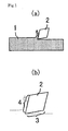
- Fig. 1 is a schematic diagram showing an example of the cutting tool according to the present invention.
- a cutting tool 1 moves relatively in the left direction of Fig. 1(a) and cuts the surface of a work piece 2.
- the cutting tools include turning tools, rotating tools and drilling tools and so on.
- flank is a face mainly contacting the work piece in the cutting tool; for example, it is a face 3 in a lathe processing tool shown in Fig. 1(b) .
- face is a face for scooping chips of the work piece; for example, it is a face 4 in the lathe processing tool shown in Fig. 1(b) .
- the coating layers composed of the following three layers is formed on a cutting tool substrate made of hard material.
- the hard material constituting the cutting tool substrate is not particularly limited, but there are listed a hard alloy typified by WC-TiC-5% Co, etc., and cermet typified by TiC-20% TiN-15% WC-10% Mo 2 C-5% Ni, etc. Among these, it is preferable to use a hard alloy from the viewpoints of thermal conductivity and relaxing of interface heat stress between the substrate and the coating layers in cutting.
- the coating layer is composed of an inner layer of AlTiN, an interlayer of TiN, and an outer layer of Al 2 O 3 .
- the AlTiN constituting the inner layer is excellent in heat resistance and wear resistance, with its performance stable up to 1000°C, and also excellent in adhesion with the cutting tool substrate. Further, Al in the inner layer dissociates due to a temperature increase during cutting, and diffuses outwardly to react with oxygen in air and thus form a protection film of Al 2 O 3 in the surface layer (outer layer) of the coatings. Therefore, the inner layer was determined to be of AlTiN. While substantially made of AlTiN, the inner layer may slightly contain impurities.
- TiN constituting the interlayer is as low as 700°C in oxidation temperature, and so it is a material originally suitable for cutting at a slow or medium speed with relatively small heat generation. However, it is excellent in adhesion and an effective substance against mechanical flaking, and therefore used for the interlayer. While substantially made of TiN, the interlayer may slightly contain impurities.
- the outer layer was determined to be of Al 2 O 3 . While substantially made of Al 2 O 3 , the outer layer may slightly contain impurities.
- the outer layer is made of a material highest in heat resistance and wear resistance
- the interlayer is made of a material most excellent in adhesion
- the inner layer is made of a material which is good in adhesion, heat resistance, and wear resistance, and from which Al dissociates and diffuses outwardly.
- the total thickness of the coating layers on the flank is preferably in the range of 2 to 80 ⁇ m. Since the flank is a place of the heaviest load during cutting with intense generation of heat, it is preferable to make the thickness of the coating layer on the flank as thick as possible.
- the total thickness is preferably 2 ⁇ m or more.
- the total thickness of the coating layers on the flank is therefore preferably in the range or 2 to 80 ⁇ m.
- the thicknesses of the inner layer (AlTiN), the interlayer (TiN), and the outer layer (Al 2 O 3 ) on the flank are 0.5 to 35 ⁇ m, 1.0 to 40 ⁇ m, and 0.5 to 5 ⁇ m, respectively.
- the thickness of the inner layer (AlTiN) on the flank is less than 0.5 ⁇ m, heat resistance might become insufficient.
- the thickness of the inner layer (AlTiN) on the flank is more than 35 ⁇ m, flaking tends to occur, only resulting in an increase in time required for film formation.
- the thickness of the inner layer (AlTiN) on the flank is 0.5 to 35 ⁇ m.
- the thickness of the interlayer (TiN) on the flank is less than 1.0 ⁇ m, heat resistance might become insufficient.
- the thickness of the interlayer (TiN) on the flank is more than 40 ⁇ m, flaking tends to occur, only resulting in an increase in time required for film formation.
- the thickness of the interlayer (TiN) on the flank is 1.0 to 40 ⁇ m.
- the thickness of the outer layer (Al 2 O 3 ) on the flank is preferably 0.5 ⁇ m or more for obtaining a sufficient heat resistance.
- the thickness of the outer layer (Al 2 O 3 ) on the flank is 0.5 to 5 ⁇ m.
- the total thickness of the coating layers on the face is preferably in the range of 2 to 40 ⁇ m.
- the face is a place which contacts with chips, and so the surface roughness is preferably as small as possible.
- coating layers are as thin as possible.
- the total thickness of the coating layers on the face is preferably 40 ⁇ m or less.
- the total thickness of the coating layers on the face is therefore preferably in the range of 2 to 40 ⁇ m.
- Thicknesses of the inner layer (AlTiN), the interlayer (TiN), and the outer layer (Al 2 O 3 ) on the face are preferably 1 to 20 ⁇ m, 1 to 20 ⁇ m, and 0.01 to 2 ⁇ m, respectively.
- the thickness of the inner layer (AlTiN) on the face is less than 1 ⁇ m, heat resistance might become insufficient.
- the thickness of the inner layer (AlTiN) on the face is more than 20 ⁇ m, not only flaking tends to occur, but also the time required for film formation increases.
- the thickness of the inner layer (AlTiN) on the face is in the range of 1 to 20 ⁇ m.
- the thickness of the interlayer (TiN) on the face is less than 1 ⁇ m, heat resistance and adhesion might become insufficient.
- the thickness of the interlayer (TiN) on the face is more than 20 ⁇ m, not only flaking tends to occur, but also the time required for film formation increases.
- the thickness of the interlayer (TiN) on the face is in the range of 1 to 20 ⁇ m.
- the thickness of the outer layer (Al 2 O 3 ) on the face is less than 0.01 ⁇ m, sufficient heat resistance and adhesion might become insufficient.
- the thickness of the outer layer (Al 2 O 3 ) on the face is more than 2 ⁇ m, not only flaking tends to occur, but also the time required for film formation increases. Hence, it is preferable that the thickness of the outer layer (Al 2 O 3 ) on the face is 0.01 to 2 ⁇ m.
- the method of producing a hard alloy or cermet as the cutting tool substrate is not particularly limited.
- it can be produced by the steps: mixing metal powder and granulating the mixture; pressing it in a mold; punched out; and sintering the resulting molded compact in a vacuum.
- the method of producing the coating layers is not particularly limited.
- it can adopt physical vapor deposition (PVD) represented by sputtering, arc ion plating, and the like, or chemical vapor deposition (CVD) represented by thermal CVD and plasma CVD.
- PVD physical vapor deposition
- CVD chemical vapor deposition
- thermal CVD and plasma CVD thermal CVD and plasma CVD.
- the gas phase of an apparatus is filled with, for example, nitrogen gas, with which the gas-phase excited target components are allowed to bond chemically on the surface of the cutting tool substrate to be coated.
- coating components are deposited on the surface of the cutting tool substrate.
- the deposited components become a chemically stable composition and adhere to the cutting tool substrate to be coated, resulting in the predetermined coating layer.
- the inner layer (AlTiN) can be formed by the following method. For example, it can be formed in such manner that mixed powder of Al and Ti powder is pressed into a desired shape, and sintered in a vacuum, ending up as a target. A PVD apparatus is filled with nitrogen gas, with which the discharge excited metal components react.
- the interlayer (TiN) of the coating layer may be produced in such manner that using Ti powder in place of the above mixed powder, Ti and nitrogen are allowed to react with one another in a state where a PVD apparatus is filled with the nitrogen gas.
- the outer layer (Al 2 O 3 ) of the coating layer may be produced in such a manner that using Al powder, Al and oxygen are allowed to react with one another in a state where a PVD apparatus is filled with the oxygen gas.
- the adjustment may be done by controlling the film coverage of the coated body by mechanically controlling the longitudinal direction/transversal direction positions of the coated body or by distorting the magnetic lines formed between the counter electrodes of the target/coated substrate with a nonequilibrium electric field.
- Aerolap lapping is a method of cleaning and mirror finishing the surface of the substrate into the submicron order by projection with flexible abrasives at high speed.
- the conventional lapping treatment involves sliding and rotating while sandwiching the upper and lower surfaces of a workpiece with plates.
- This treatment is in a wet process because water dispersion of alumina or glass fine powders of a submicron order in particle diameter as a polishing agent is poured into a sliding interface.
- Such lapping treatment is limited to lapping for a plane article, and so the lapping of a rounded part, an inclined part, and the like is difficult structurally.
- the present inventors focused on Aerolap lapping, which is capable of lapping of the rounded part and the inclined part.
- Aerolap lapping adjusts the surface roughness of the cutting tool substrate uniformly and can improve its adhesion with the coating layers, and further, can physically remove impurities off the surface of the cutting tool substrate that could not be completely removed by the conventional wet cleaning. That is, with Aerolap lapping, the adhesion between the cutting tool substrate and the coating layers that cannot be explained merely by surface roughness can be enhanced, thereby improving the tool life remarkably.
- the flexible abrasives is a particulate polishing material in which an abrasive grain of micron meter diameter is used as a core material, and the core material is covered with a polymer type resin.
- abrasive grain at least one of diamond, silicon carbide, and alumina may be used.
- the grain size of the abrasive grain is preferably in the range of 3000 to 10000 meshes.
- the polymer type resin is not particularly limited, and gelatin with desired elasticity and viscosity by containing water can be used. When gelatin is used, the diameter of the flexible abrasive is preferably in the range of 0.1 to 2 mm.
- a multi-liquid for the polymer type resin can contain a water-soluble oil as an evaporation preventing material.
- the evaporation preventing material for example, ethylene glycol, sorbitol, and the like can be used.
- the cutting tool of example 1 of the present invention was produced in the following manner.
- the cutting tool substrate was placed in a PVD apparatus, a mixed sintered body of Al and Ti was used as a target, nitrogen gas was filled therein, and each metal excited by discharge and nitrogen were allowed to react with one another to form a inner layer of AlTiN on the cutting tool substrate.
- the Ti target was excited by discharge under a nitrogen atmosphere to form an interlayer of TiN
- the Al target was excited by discharge under an oxygen atmosphere to form an outer layer of Al 2 O 3 .
- respective thicknesses of the flank and face of each layer were adjusted by distorting magnetic lines formed between the counter electrodes of target/coated substrate with a nonequilibrium electric field and by intentionally changing the film coverage of the coated body.
- the cutting tools thus obtained were analyzed for performance of surface roughness, coefficient of friction, and adhesion, and also their tool lives were compared after cutting an alloy (Sl3Cr) containing 5% nickel of 85 mm outer diameter and 500 mm length at a temperature of 800°C or more and at a cutting speed of 70 m/min.
- alloy Si3Cr
- surface roughness was measured as "arithmetic mean roughness Ra" as defined by JIS B 0601-1994 in such a manner that a length of 10 mm of an arbitrary film-coated surface was scanned using a sensing pin (pin made of diamond; outer diameter 25 ⁇ m).
- the coefficient of friction was measured using a Bauden type sliding tester under sliding conditions of 5N in load, room temperature, 4 mm/s in speed, and steel ball made of SUS of 5 mm in diameter.
- the adhesion was measured in such a manner that using a scratch type tester, scanning was conducted with a diamond sensing pin of 200 ⁇ m in outer diameter under a load in the range of 0 to 100 N, at a scanning speed of 10 mm/min and a load speed 100 N/min, and the load value at which an abnormal vibration signal was detected was defined as film breakage and assumed the adhesion force.
- tool life means the number of work pieces that were able to be cut without any one of the situations shown in (1) to (3) below.
- Table 1 Classification Base metal Coating layers Physical properties inner layer Interlayer Outer layer Surface roughness Ra ( ⁇ m) Coefficient of friction Adhesion force (N) Cutting life (number of pieces treated) Composition Thickness ( ⁇ m) Composition Thickness ( ⁇ m) Composition Thickness ( ⁇ m) Example 1 Flank WC-TiC-Co AlTiN 10 TiN 10 Al 2 O 3 3 0.05 0.65 ⁇ 100 195 face WC-TiC-Co AlTiN 5 TiN 5 Al 2 O 3 2 0.04 0.57 ⁇ 100 Comparative Example 1 Flank WC-TiC-Co TiCN 10 Al 2 O 3 10 TiN 8 0.07 0.82 ⁇ 80 58 face WC-TiC-Co TiCN 8 Al 2 O 3 8 TiN 10 0.09 0.78 ⁇ 80
- This substrate was used to form a tool (example 2 of the present invention) on which coating layers ware formed without subjecting any treatment on and a tool (example 3 of the present invention) on which coating layers ware formed after subjecting lapping treatment by Aerolap lapping.
- the lapping treatment by Aerolap lapping was subjected using a polishing material of 0.5 to 2.0 mm in particle diameter formed by compounding a diamond abrasive grain of 3000 meshes with a polymer type resin.
- Each cutting tool substrate was placed in a PVD apparatus, which was then filled with nitrogen gas with a mixed sintered body of Al and Ti as a target, and each metal excited by discharge and nitrogen were allowed to react with one another to form a inner layer of AlTiN on the cutting tool substrate. Thereafter, in the PVD apparatus, the Ti target was excited by discharge under a nitrogen atmosphere to form an interlayer of TiN, and further, the Al target was excited by discharge under an oxygen atmosphere to form an outer layer of Al 2 O 3 , thereby producing a chaser for cutting thread.
- the tool life was measured in the following manner that using the chaser for cutting thread produced by the above method, an alloy containing 5% nickel (Sl3Cr steel) of 139.7 mm outer diameter x 11000 mm length was subjected to VAM-TOP outer diameter thread cutting by four cutting machines at a temperature of 800°C or more and at a cutting speed of 90 m/min, in order to examine the tool life during cutting.
- the term tool life means the number of work pieces that were able to be cut without any one of the situations shown in foregoing (1) to (3). On the basis of this evaluation criterion, the average tool life of the four cutting machines and a standard deviation were obtained.
- Al in the inner layer dissociates during cutting and diffuses outwardly to form Al 2 O 3 in the vicinity of the surface of the coating layers to compensate for the outer layer. Therefore, excellent heat resistance and wear resistance can be stably obtained, which can provide a cutting tool with a long tool life. Further, according to a preferred embodiment of the present invention that subjects Aerolap lapping, the adhesion between the cutting tool substrate and the coating layers improves, and so a cutting tool with a longer tool life can be provided. This cutting tool is useful particularly as a chaser for cutting thread used in severe cutting conditions such as thread cutting of hard steel materials.
- FIG. 1 Schematic diagram showing an example of a cutting tool according to the present invention.
Landscapes
- Engineering & Computer Science (AREA)
- Mechanical Engineering (AREA)
- Chemical & Material Sciences (AREA)
- Chemical Kinetics & Catalysis (AREA)
- Materials Engineering (AREA)
- Metallurgy (AREA)
- Organic Chemistry (AREA)
- Cutting Tools, Boring Holders, And Turrets (AREA)
Applications Claiming Priority (3)
| Application Number | Priority Date | Filing Date | Title |
|---|---|---|---|
| JP2006086773A JP2007260806A (ja) | 2006-03-28 | 2006-03-28 | 切削工具 |
| JP2006097318A JP5053561B2 (ja) | 2006-03-31 | 2006-03-31 | 切削工具およびその製造方法 |
| PCT/JP2007/056185 WO2007111293A1 (ja) | 2006-03-28 | 2007-03-26 | 切削工具およびその製造方法 |
Publications (2)
| Publication Number | Publication Date |
|---|---|
| EP2000236A1 true EP2000236A1 (de) | 2008-12-10 |
| EP2000236A4 EP2000236A4 (de) | 2012-01-25 |
Family
ID=38541210
Family Applications (1)
| Application Number | Title | Priority Date | Filing Date |
|---|---|---|---|
| EP07739623A Withdrawn EP2000236A4 (de) | 2006-03-28 | 2007-03-26 | Schneidwerkzeug und herstellungsverfahren dafür |
Country Status (6)
| Country | Link |
|---|---|
| US (1) | US7704593B2 (de) |
| EP (1) | EP2000236A4 (de) |
| BR (1) | BRPI0710255B1 (de) |
| IL (1) | IL194149A (de) |
| MX (1) | MX2008012236A (de) |
| WO (1) | WO2007111293A1 (de) |
Cited By (1)
| Publication number | Priority date | Publication date | Assignee | Title |
|---|---|---|---|---|
| DE102012000540A1 (de) | 2011-02-07 | 2012-08-09 | Kennametal Inc. | Beschichtung aus kubischem Aluminiumtitannitrid und Verfahren zu deren Herstellung |
Families Citing this family (8)
| Publication number | Priority date | Publication date | Assignee | Title |
|---|---|---|---|---|
| KR101385262B1 (ko) * | 2008-04-29 | 2014-04-16 | 에이전시 포 사이언스, 테크놀로지 앤드 리서치 | 무기 그레이디드 장벽 필름 및 그 제조 방법들 |
| US8277958B2 (en) * | 2009-10-02 | 2012-10-02 | Kennametal Inc. | Aluminum titanium nitride coating and method of making same |
| AT510713B1 (de) * | 2011-03-18 | 2012-06-15 | Boehlerit Gmbh & Co Kg | Schneidwerkzeug oder schneideinsatz hierfür sowie verwendung dieser |
| US9103036B2 (en) | 2013-03-15 | 2015-08-11 | Kennametal Inc. | Hard coatings comprising cubic phase forming compositions |
| US9896767B2 (en) | 2013-08-16 | 2018-02-20 | Kennametal Inc | Low stress hard coatings and applications thereof |
| US9168664B2 (en) | 2013-08-16 | 2015-10-27 | Kennametal Inc. | Low stress hard coatings and applications thereof |
| JP6569376B2 (ja) * | 2015-08-13 | 2019-09-04 | 日本製鉄株式会社 | 超硬工具及びその製造方法 |
| WO2020213259A1 (ja) * | 2019-04-17 | 2020-10-22 | 住友電工ハードメタル株式会社 | 切削工具 |
Family Cites Families (23)
| Publication number | Priority date | Publication date | Assignee | Title |
|---|---|---|---|---|
| JPH0765183B2 (ja) * | 1989-10-30 | 1995-07-12 | 東芝タンガロイ株式会社 | 断続切削用被覆超硬合金 |
| JP3146677B2 (ja) | 1992-09-24 | 2001-03-19 | 凸版印刷株式会社 | 天然抗酸化物質の製造方法 |
| US5722803A (en) * | 1995-07-14 | 1998-03-03 | Kennametal Inc. | Cutting tool and method of making the cutting tool |
| US5879823A (en) * | 1995-12-12 | 1999-03-09 | Kennametal Inc. | Coated cutting tool |
| JPH10287491A (ja) | 1997-04-10 | 1998-10-27 | Toshiba Tungaloy Co Ltd | 表面粗さを調整したダイヤモンド被覆硬質部材 |
| JP3418336B2 (ja) * | 1998-03-31 | 2003-06-23 | 日本特殊陶業株式会社 | サーメット工具 |
| JP3343727B2 (ja) * | 1999-05-19 | 2002-11-11 | 日立ツール株式会社 | 硬質皮膜被覆工具 |
| JP2001031949A (ja) * | 1999-07-22 | 2001-02-06 | Sumitomo Bakelite Co Ltd | 弾性材被覆研磨材 |
| US6733874B2 (en) * | 2001-08-31 | 2004-05-11 | Mitsubishi Materials Corporation | Surface-coated carbide alloy cutting tool |
| JP4251990B2 (ja) | 2002-01-18 | 2009-04-08 | 住友電工ハードメタル株式会社 | 表面被覆切削工具 |
| US6660133B2 (en) * | 2002-03-14 | 2003-12-09 | Kennametal Inc. | Nanolayered coated cutting tool and method for making the same |
| JP2004188502A (ja) | 2002-06-28 | 2004-07-08 | Mitsubishi Materials Corp | 硬質被覆層がすぐれた耐熱衝撃性を有する表面被覆サーメット製切削工具 |
| JP2004188575A (ja) | 2002-06-28 | 2004-07-08 | Mitsubishi Materials Corp | 硬質被覆層がすぐれた耐熱衝撃性を有する表面被覆サーメット製切削工具 |
| JP2004188500A (ja) | 2002-06-28 | 2004-07-08 | Mitsubishi Materials Corp | 硬質被覆層がすぐれた耐熱衝撃性を有する表面被覆サーメット製切削工具 |
| JP3971293B2 (ja) * | 2002-08-08 | 2007-09-05 | 株式会社神戸製鋼所 | 耐摩耗性および耐熱性に優れた積層皮膜およびその製造方法、並びに耐摩耗性および耐熱性に優れた積層皮膜被覆工具 |
| CN100413998C (zh) * | 2002-08-08 | 2008-08-27 | 株式会社神户制钢所 | α型晶体结构为主体的氧化铝被膜相关技术 |
| JP2003311505A (ja) * | 2003-03-28 | 2003-11-05 | Ngk Spark Plug Co Ltd | サーメット工具及びサーメット工具の摩耗識別方法 |
| JP4485146B2 (ja) | 2003-05-28 | 2010-06-16 | 三菱マテリアル株式会社 | 高速切削加工で硬質被覆層がすぐれた耐摩耗性を発揮する表面被覆サーメット製切削工具 |
| JP4205546B2 (ja) * | 2003-09-16 | 2009-01-07 | 株式会社神戸製鋼所 | 耐摩耗性、耐熱性および基材との密着性に優れた積層皮膜の製造方法 |
| JP4398224B2 (ja) * | 2003-11-05 | 2010-01-13 | 住友電工ハードメタル株式会社 | 耐摩耗性部材 |
| JP2005271153A (ja) * | 2004-03-25 | 2005-10-06 | Tdk Corp | 膜除去用粒子 |
| JP2006028600A (ja) * | 2004-07-16 | 2006-02-02 | Kobe Steel Ltd | 耐摩耗性と耐熱性に優れた積層皮膜 |
| SE528380C2 (sv) * | 2004-11-08 | 2006-10-31 | Sandvik Intellectual Property | Belagt skär för torrfräsning, sätt och användning av detsamma |
-
2007
- 2007-03-26 EP EP07739623A patent/EP2000236A4/de not_active Withdrawn
- 2007-03-26 WO PCT/JP2007/056185 patent/WO2007111293A1/ja not_active Ceased
- 2007-03-26 BR BRPI0710255A patent/BRPI0710255B1/pt not_active IP Right Cessation
- 2007-03-26 MX MX2008012236A patent/MX2008012236A/es unknown
-
2008
- 2008-09-16 IL IL194149A patent/IL194149A/en not_active IP Right Cessation
- 2008-09-26 US US12/232,924 patent/US7704593B2/en not_active Expired - Fee Related
Cited By (1)
| Publication number | Priority date | Publication date | Assignee | Title |
|---|---|---|---|---|
| DE102012000540A1 (de) | 2011-02-07 | 2012-08-09 | Kennametal Inc. | Beschichtung aus kubischem Aluminiumtitannitrid und Verfahren zu deren Herstellung |
Also Published As
| Publication number | Publication date |
|---|---|
| IL194149A (en) | 2011-11-30 |
| BRPI0710255A2 (pt) | 2011-08-09 |
| MX2008012236A (es) | 2009-02-10 |
| EP2000236A4 (de) | 2012-01-25 |
| WO2007111293A1 (ja) | 2007-10-04 |
| US20090098372A1 (en) | 2009-04-16 |
| BRPI0710255B1 (pt) | 2019-08-13 |
| US7704593B2 (en) | 2010-04-27 |
Similar Documents
| Publication | Publication Date | Title |
|---|---|---|
| US7704593B2 (en) | Cutting tool and method of producing the same | |
| JP4846872B2 (ja) | スパッタリングターゲット及びその製造方法 | |
| JP5344204B2 (ja) | 表面被覆切削工具 | |
| EP2594352B1 (de) | Oberflächenbeschichtetes schneidewerkzeug | |
| Liu et al. | Cutting Performance and Wear Behavior of AlTiN-and TiAlSiN-Coated Carbide Tools During Dry Milling of Ti–6Al–4V: J. Liu et al. | |
| EP3446814A1 (de) | Oberflächenbeschichtetes schneidwerkzeug | |
| KR20110033266A (ko) | 피복 부재 | |
| EP4108366A1 (de) | Beschichtetes werkzeug | |
| JP5239292B2 (ja) | 硬質被覆層がすぐれた耐欠損性を発揮する表面被覆切削工具 | |
| JP2006281363A (ja) | 表面被覆部材および表面被覆切削工具 | |
| JP2009056540A (ja) | 硬質被覆層がすぐれた耐欠損性を発揮する表面被覆切削工具 | |
| EP3943222A1 (de) | Beschichtetes schneidwerkzeug | |
| JP5035956B2 (ja) | 硬質被覆層がすぐれた耐欠損性を発揮する表面被覆切削工具 | |
| JP7183522B2 (ja) | 硬質被覆層が優れた耐チッピング性を発揮する表面被覆切削工具 | |
| JP2010017785A (ja) | 硬質被覆層がすぐれた耐欠損性を発揮する表面被覆切削工具 | |
| JP4427729B2 (ja) | 硬質被覆層がすぐれた耐チッピング性を有する表面被覆立方晶窒化硼素系焼結材料製切削工具 | |
| CN112770858A (zh) | 硬质包覆层发挥优异的耐崩刃性的表面包覆切削工具 | |
| CN115397589B (zh) | 表面包覆切削工具 | |
| JP2009214196A (ja) | 硬質被覆層がすぐれた耐欠損性を発揮する表面被覆切削工具 | |
| JP4991244B2 (ja) | 表面被覆切削工具 | |
| JP2006021257A (ja) | 潤滑被覆層がすぐれた耐摩耗性を発揮する表面被覆超硬合金製切削工具 | |
| JP5309733B2 (ja) | 硬質被覆層がすぐれた耐欠損性を発揮する表面被覆切削工具 | |
| JP5053561B2 (ja) | 切削工具およびその製造方法 | |
| CN101410209A (zh) | 切削工具及其制造方法 | |
| JP4569862B2 (ja) | 硬質被覆層がすぐれた耐チッピング性を発揮する表面被覆サーメット製切削工具 |
Legal Events
| Date | Code | Title | Description |
|---|---|---|---|
| PUAI | Public reference made under article 153(3) epc to a published international application that has entered the european phase |
Free format text: ORIGINAL CODE: 0009012 |
|
| 17P | Request for examination filed |
Effective date: 20080918 |
|
| AK | Designated contracting states |
Kind code of ref document: A1 Designated state(s): AT BE BG CH CY CZ DE DK EE ES FI FR GB GR HU IE IS IT LI LT LU LV MC MT NL PL PT RO SE SI SK TR |
|
| RIN1 | Information on inventor provided before grant (corrected) |
Inventor name: FUJI, TAKASHIC/O SUMITOMO METAL INDUSTRIES, LTD. Inventor name: ISHII, KAZUHIROC/O SUMITOMO METAL INDUSTRIES, LTD. Inventor name: KANDA, OSAMUC/O SUMITOMO METAL INDUSTRIES, LTD. |
|
| A4 | Supplementary search report drawn up and despatched |
Effective date: 20111227 |
|
| RIC1 | Information provided on ipc code assigned before grant |
Ipc: C23C 14/06 20060101ALI20111220BHEP Ipc: B24C 1/00 20060101ALI20111220BHEP Ipc: B24C 1/10 20060101ALI20111220BHEP Ipc: C23C 30/00 20060101ALI20111220BHEP Ipc: B23B 27/14 20060101AFI20111220BHEP Ipc: B24C 11/00 20060101ALI20111220BHEP |
|
| DAX | Request for extension of the european patent (deleted) | ||
| STAA | Information on the status of an ep patent application or granted ep patent |
Free format text: STATUS: THE APPLICATION IS DEEMED TO BE WITHDRAWN |
|
| 18D | Application deemed to be withdrawn |
Effective date: 20120724 |
|
| RAP1 | Party data changed (applicant data changed or rights of an application transferred) |
Owner name: NIPPON STEEL & SUMITOMO METAL CORPORATION |