EP1998920B1 - Hartmetallschneidwerkzeug und verfahren zur herstellung eines solchen werkzeugs - Google Patents
Hartmetallschneidwerkzeug und verfahren zur herstellung eines solchen werkzeugs Download PDFInfo
- Publication number
- EP1998920B1 EP1998920B1 EP07719194A EP07719194A EP1998920B1 EP 1998920 B1 EP1998920 B1 EP 1998920B1 EP 07719194 A EP07719194 A EP 07719194A EP 07719194 A EP07719194 A EP 07719194A EP 1998920 B1 EP1998920 B1 EP 1998920B1
- Authority
- EP
- European Patent Office
- Prior art keywords
- blades
- tool
- spindle
- base
- blade
- Prior art date
- Legal status (The legal status is an assumption and is not a legal conclusion. Google has not performed a legal analysis and makes no representation as to the accuracy of the status listed.)
- Active
Links
Images


Classifications
-
- B—PERFORMING OPERATIONS; TRANSPORTING
- B26—HAND CUTTING TOOLS; CUTTING; SEVERING
- B26D—CUTTING; DETAILS COMMON TO MACHINES FOR PERFORATING, PUNCHING, CUTTING-OUT, STAMPING-OUT OR SEVERING
- B26D1/00—Cutting through work characterised by the nature or movement of the cutting member or particular materials not otherwise provided for; Apparatus or machines therefor; Cutting members therefor
- B26D1/01—Cutting through work characterised by the nature or movement of the cutting member or particular materials not otherwise provided for; Apparatus or machines therefor; Cutting members therefor involving a cutting member which does not travel with the work
- B26D1/12—Cutting through work characterised by the nature or movement of the cutting member or particular materials not otherwise provided for; Apparatus or machines therefor; Cutting members therefor involving a cutting member which does not travel with the work having a cutting member moving about an axis
- B26D1/25—Cutting through work characterised by the nature or movement of the cutting member or particular materials not otherwise provided for; Apparatus or machines therefor; Cutting members therefor involving a cutting member which does not travel with the work having a cutting member moving about an axis with a non-circular cutting member
- B26D1/34—Cutting through work characterised by the nature or movement of the cutting member or particular materials not otherwise provided for; Apparatus or machines therefor; Cutting members therefor involving a cutting member which does not travel with the work having a cutting member moving about an axis with a non-circular cutting member moving about an axis parallel to the line of cut
- B26D1/36—Cutting through work characterised by the nature or movement of the cutting member or particular materials not otherwise provided for; Apparatus or machines therefor; Cutting members therefor involving a cutting member which does not travel with the work having a cutting member moving about an axis with a non-circular cutting member moving about an axis parallel to the line of cut and rotating continuously in one direction during cutting, e.g. mounted on a rotary cylinder
-
- B—PERFORMING OPERATIONS; TRANSPORTING
- B23—MACHINE TOOLS; METAL-WORKING NOT OTHERWISE PROVIDED FOR
- B23C—MILLING
- B23C5/00—Milling-cutters
- B23C5/02—Milling-cutters characterised by the shape of the cutter
- B23C5/04—Plain cutters, i.e. having essentially a cylindrical or tapered cutting surface of substantial length
-
- B—PERFORMING OPERATIONS; TRANSPORTING
- B02—CRUSHING, PULVERISING, OR DISINTEGRATING; PREPARATORY TREATMENT OF GRAIN FOR MILLING
- B02C—CRUSHING, PULVERISING, OR DISINTEGRATING IN GENERAL; MILLING GRAIN
- B02C18/00—Disintegrating by knives or other cutting or tearing members which chop material into fragments
- B02C18/06—Disintegrating by knives or other cutting or tearing members which chop material into fragments with rotating knives
- B02C18/16—Details
- B02C18/18—Knives; Mountings thereof
- B02C18/186—Axially elongated knives
-
- B—PERFORMING OPERATIONS; TRANSPORTING
- B23—MACHINE TOOLS; METAL-WORKING NOT OTHERWISE PROVIDED FOR
- B23C—MILLING
- B23C5/00—Milling-cutters
- B23C5/16—Milling-cutters characterised by physical features other than shape
- B23C5/20—Milling-cutters characterised by physical features other than shape with removable cutter bits or teeth or cutting inserts
- B23C5/22—Securing arrangements for bits or teeth or cutting inserts
-
- B—PERFORMING OPERATIONS; TRANSPORTING
- B23—MACHINE TOOLS; METAL-WORKING NOT OTHERWISE PROVIDED FOR
- B23D—PLANING; SLOTTING; SHEARING; BROACHING; SAWING; FILING; SCRAPING; LIKE OPERATIONS FOR WORKING METAL BY REMOVING MATERIAL, NOT OTHERWISE PROVIDED FOR
- B23D25/00—Machines or arrangements for shearing stock while the latter is travelling otherwise than in the direction of the cut
- B23D25/12—Shearing machines with blades on coacting rotating drums
-
- B—PERFORMING OPERATIONS; TRANSPORTING
- B23—MACHINE TOOLS; METAL-WORKING NOT OTHERWISE PROVIDED FOR
- B23C—MILLING
- B23C2224/00—Materials of tools or workpieces composed of a compound including a metal
- B23C2224/24—Titanium aluminium nitride (TiAlN)
-
- B—PERFORMING OPERATIONS; TRANSPORTING
- B23—MACHINE TOOLS; METAL-WORKING NOT OTHERWISE PROVIDED FOR
- B23C—MILLING
- B23C2224/00—Materials of tools or workpieces composed of a compound including a metal
- B23C2224/32—Titanium carbide nitride (TiCN)
-
- B—PERFORMING OPERATIONS; TRANSPORTING
- B23—MACHINE TOOLS; METAL-WORKING NOT OTHERWISE PROVIDED FOR
- B23C—MILLING
- B23C2224/00—Materials of tools or workpieces composed of a compound including a metal
- B23C2224/36—Titanium nitride
-
- B—PERFORMING OPERATIONS; TRANSPORTING
- B23—MACHINE TOOLS; METAL-WORKING NOT OTHERWISE PROVIDED FOR
- B23C—MILLING
- B23C2226/00—Materials of tools or workpieces not comprising a metal
- B23C2226/18—Ceramic
-
- Y—GENERAL TAGGING OF NEW TECHNOLOGICAL DEVELOPMENTS; GENERAL TAGGING OF CROSS-SECTIONAL TECHNOLOGIES SPANNING OVER SEVERAL SECTIONS OF THE IPC; TECHNICAL SUBJECTS COVERED BY FORMER USPC CROSS-REFERENCE ART COLLECTIONS [XRACs] AND DIGESTS
- Y10—TECHNICAL SUBJECTS COVERED BY FORMER USPC
- Y10T—TECHNICAL SUBJECTS COVERED BY FORMER US CLASSIFICATION
- Y10T407/00—Cutters, for shaping
- Y10T407/19—Rotary cutting tool
- Y10T407/1906—Rotary cutting tool including holder [i.e., head] having seat for inserted tool
- Y10T407/1934—Rotary cutting tool including holder [i.e., head] having seat for inserted tool with separate means to fasten tool to holder
-
- Y—GENERAL TAGGING OF NEW TECHNOLOGICAL DEVELOPMENTS; GENERAL TAGGING OF CROSS-SECTIONAL TECHNOLOGIES SPANNING OVER SEVERAL SECTIONS OF THE IPC; TECHNICAL SUBJECTS COVERED BY FORMER USPC CROSS-REFERENCE ART COLLECTIONS [XRACs] AND DIGESTS
- Y10—TECHNICAL SUBJECTS COVERED BY FORMER USPC
- Y10T—TECHNICAL SUBJECTS COVERED BY FORMER US CLASSIFICATION
- Y10T407/00—Cutters, for shaping
- Y10T407/19—Rotary cutting tool
- Y10T407/1906—Rotary cutting tool including holder [i.e., head] having seat for inserted tool
- Y10T407/1942—Peripherally spaced tools
-
- Y—GENERAL TAGGING OF NEW TECHNOLOGICAL DEVELOPMENTS; GENERAL TAGGING OF CROSS-SECTIONAL TECHNOLOGIES SPANNING OVER SEVERAL SECTIONS OF THE IPC; TECHNICAL SUBJECTS COVERED BY FORMER USPC CROSS-REFERENCE ART COLLECTIONS [XRACs] AND DIGESTS
- Y10—TECHNICAL SUBJECTS COVERED BY FORMER USPC
- Y10T—TECHNICAL SUBJECTS COVERED BY FORMER US CLASSIFICATION
- Y10T407/00—Cutters, for shaping
- Y10T407/27—Cutters, for shaping comprising tool of specific chemical composition
Definitions
- the present invention relates to a cutting tool with knives or blades having a reinforced resistance to wear, in particular for the cutting into granules of any synthetic or mineral material made of wire (plastic, fiberglass, etc.), coated or not, before its use as raw material.
- the invention relates to a rotary cutting tool having a plurality of individual cutting edges arranged regularly or not about an axis.
- the invention also relates to a method of manufacturing such a tool.
- the outgoing son are then cut into granules by rotating blades.
- the cutting edges of these blades are generally helical for a better distribution of effort and to avoid vibrations, the son being then cut successively and not simultaneously.
- the state of the art offers many applications of knives of this type with helical sharpening of the blades.
- These can be machined in the mass, that is to say that the piece is monoblock, made of high-alloy or sintered high speed steel, of Rockwell C hardness of at least greater than 60 (for example GB-A-2 364 007 , FR-A-2,301,327 , GB-A-923 087 , JP-A-2000/107925 ).
- They can also be in the form of pads made of a wear-resistant material, such as tungsten carbide, high-speed steel or ceramic, optionally coated.
- the cutting inserts are secured to the body of the cutting tool by soldering, crimping or clamping, non-metallic bonding, etc. (for example US Patent 5,586,843 , GB-A-1334676 , GB-A-2,116,094 ).
- the knives with helical cutting edges are arranged axially over the entire length of the cylindrical support body .
- the positioning and the joining of individual blades thereon are extremely delicate operations in view of the tolerance to be respected for the final sharpening, especially for helical blades.
- the document FR-A-1,278,615 discloses a milling cutter consisting of a cylindrical part provided with straight milled grooves inclined relative to the generatrix of the cylinder, in which are accommodated rod-shaped blades. The cutting edges are evenly distributed around the edge of the strawberry body.
- the document DE 10 2004 017 714 A1 describes a milling tool having rectilinear grooves oriented obliquely to the axis of the tool.
- the blades are fixed to the tool by means of longitudinal locking pieces blocked by means of screws.
- the present invention aims to provide a solution that makes it possible to overcome the disadvantages of the state of the art.
- the invention aims to provide a cutting tool for granulator whose life in use is significantly increased.
- the invention also aims to provide a cutting tool that is cheaper than the tools of the state of the art in terms of manufacture and repair.
- the invention also aims to provide a simple and economical method of manufacturing and sharpening the cutting tool according to the invention.
- a first aspect of the present invention relates to a rotary cutting tool having a cylindrical support mandrel and a plurality of individual blades with substantially radial cutting edges, which are helically sharpened and arranged regularly on the outer surface of the mandrel, each blade having a rectilinear base which has just been removed. inserting into a groove of the same shape as said base, each individual blade being mounted mechanically fixed to the mandrel, characterized in that it further comprises two lids fixed to the respective bases of the mandrel to strengthen the attachment of the blades.
- the base is substantially rectangular or has the shape of a parallelogram and the groove is respectively rectangular section or parallelogram.
- the mechanical attachment of the blades to the mandrel is obtained by screwing, clamping, brazing, shrinking, crimping or gluing.
- the blades are mounted screwed to the mandrel by means of frustoconical screws.
- the mandrel has blade supports provided with transverse grooves regularly spaced for the positioning of the screws.
- the screws are arranged regularly along the blades, in the grooves of the blade supports, so as to block them by means of screw heads in the corresponding rectilinear grooves.
- the blades extend over the entire length of the mandrel with a monotonous and regular cutting profile, devoid of teeth over the entire length of the blades.
- the grooves machined in the mandrel are inclined at an angle of between 0 ° and 15 °, and preferably between 5 ° and 15 °, relative to the axis of the mandrel. .
- the blades are cemented carbide based on tungsten carbide, high-speed steel or high-strength, diamond, ceramic or cermet, optionally coated with titanium nitride, titanium aluminum nitride or titanium carbonitride, mono- or multilayer chromium nitride.
- the mandrel is made of stainless steel.
- each blade comprises at least two parallel cutting edges with helical sharpening.
- the blades have at least one frustoconical end which cooperates, during attachment, with an inverted cone machined in the corresponding cover.
- At least one of the two covers is split radially and has a screw hole between any two slots, so that there are at most two cutting edges between any two slots.
- the aforementioned groove is trapezoidal section, the large base of the trapezium being closer to the axis of the mandrel than the small base.
- the mandrel has removable locking pieces, in the form of strips having the same length as the blades, being able to be arranged axially along them and forming the grooves when in position, said locking pieces having housings for inserting fastening screws on the mandrel.
- each locking piece is configured for fixing two adjacent blades.
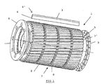
- the figure 1 is an exploded perspective view of the cutting tool according to a preferred embodiment of the present invention.
- the Figures 2A and 2B respectively represent an elevational view and a sectional view of the support mandrel of the cutting tool according to the figure 1 .
- FIGS. 3A and 3B represent respective views of the bases of the aforementioned mandrel.
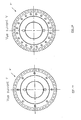
- the Figures 4A and 4B respectively represent a sectional view and a plan view of the lid corresponding to the base of the figure 3A .
- the Figures 5A and 5B respectively represent a sectional view and a plan view of the lid corresponding to the base of the figure 3B .
- the cutting tool 1 comprises a cylindrical mandrel 2 blade holder, made for example of steel or stainless steel.
- the blades 3 are made of a material having a high resistance to wear, such as, for example, tungsten carbide (WC), ceramic, high-speed steel, etc., optionally coated with titanium nitride ( TiN), titanium carbonitride (TiCN), titanium aluminum nitride (TiAlN), chromium nitride (CrN), etc.
- the raw blades or blanks are substantially in the form of rectangular parallelepipeds or straight-line bars roughly sharpened and are fixed on the lateral surface of the cylindrical mandrel 2 in grooves 5 by mechanical means, for example by locking at
- the blades 3 are oriented parallel to each other at an angle of about 10 degrees to the axis of the cylinder 2. This inclination will allow the blades to be sharpened.
- helical finish to have a larger helix angle than blades arranged axially.
- the mandrel 2 is provided with a plurality of rectilinear grooves 5, with a flat bottom, for fixing the blanks of blades 3, whose base 4 is of corresponding shape, that is to say rectangular or parallelogram ( figures 1 , 2A and 2B ). Once these are fixed to the mandrel, it can then easily achieve the finishing sharpening of the blades according to the required tolerances.
- the mandrel 2 thus has blade supports 3 'themselves having a plurality of transverse grooves 7, for example three in number, spaced regularly and allowing the introduction of the aforementioned conical screws 6.
- the invention is not limited to screw fastening blanks blades, but any mechanical means such as crimping, clamping, heat shrinking, clamping, brazing, gluing, etc., can be considered within the limits of the invention.
- the blade blanks 3 and the mandrel 2 can be dimensioned such that, over the width of the rectilinear grooves 5 machined in the mandrel, it is possible to insert a blade having two cutting edges (not shown).
- the attachment of the blades 3 is reinforced by the additional attachment of two lids 8, 9 with inverted cones with respect to the bases 8 ', 9' of the mandrel 2.
- the blades 3 therefore have at least one frustoconical end 4 'which cooperates, when fastening the assembly, with an inverted cone machined in the corresponding cover 8.
- At least one of the two covers (cover 9, figures 1 and 5B ) is split radially and has a screw hole 10 between any two slots 11, so that there is at most two blades between two slots, given what is specified above.
- the grooves 5 are of trapezoidal section, the large base of the trapezium 5 'being closer to the axis of the mandrel 2 than the small base 5 "Thus, the securing of the blades 3, which tend to be ejected when the mandrel is in motion, following the effect of the centrifugal force
- the mandrel 2 is then designed to receive removable locking pieces 3 ', in the form of bars of the same length as the blades 3, which can be arranged axially along the blades 3 and forming the grooves 5 when in position, the shoulders are milled in the mandrel against which the blades 3 are placed.
- the fastening screws here can be of any type well known to those skilled in the art.
- a locking piece 3 ' can be provided for fixing two adjacent blades 3, as shown in FIG. figure 6 .
- the invention has the following advantages.
- carbide can greatly increase the service life of the blades and thus reduce downtime in production.
- each tool is interchangeable and removable. Because of the individual attachment of each blade to the blade holder, any defective blade can be replaced separately, which significantly reduces the cost of repair compared to the monobloc device. In addition, each tool can be delivered with two sets of blades.
- the machining cost of a mandrel and separate bars is less than that of a single piece.
Landscapes
- Engineering & Computer Science (AREA)
- Mechanical Engineering (AREA)
- Food Science & Technology (AREA)
- Life Sciences & Earth Sciences (AREA)
- Forests & Forestry (AREA)
- Milling Processes (AREA)
- Processing And Handling Of Plastics And Other Materials For Molding In General (AREA)
- Cutting Tools, Boring Holders, And Turrets (AREA)
- Drilling Tools (AREA)
- Powder Metallurgy (AREA)
- Turning (AREA)
Claims (17)
- Rotierendes Schnittwerkzeug (1), das über eine zylindrische Spindel als Träger (2) und mehrere einzelne Klingen (3) mit im Wesentlichen radialen, schneidenden Kanten verfügt, die spiralenförmig geschärft und in regelmäßigen Abständen auf der Außenfläche der Spindel angeordnet sind, wobei jede Klinge (3) hierbei eine geradlinige Grundfläche (4), welche sich in eine gleichförmige Rille (5) der besagten Grundfläche einfügt, umfasst; jede einzelne Klinge (3) ist mechanisch fest auf der Spindel (2) montiert, und dadurch gekennzeichnet, dass es darüber hinaus zwei Deckel (8, 9) umfasst, die an den jeweiligen Grundflächen (8', 9') der Spindel (2) befestigt sind, um die Befestigung der Klingen (3) zu verstärken.
- Werkzeug gemäß dem Anspruch 1, dadurch gekennzeichnet, dass diese Grundfläche (4) im Wesentlichen rechteckig ist oder die Form eines Parallelogramms hat und dass die Rille (5) jeweils den gleichen rechteckigen oder parallelogrammförmigen Querschnitt hat.
- Werkzeug gemäß den Ansprüchen 1 bzw. 2, dadurch gekennzeichnet, dass die mechanische Befestigung der Klingen (3) auf der Spindel durch Verschraubung, Einspannen, Versteifen, Bördeln oder Verkleben erfolgt.
- Werkzeug gemäß den Ansprüchen 1, 2 bzw. 3, dadurch gekennzeichnet, dass diese Klingen mithilfe von Flachkopfschrauben (6) an der Spindel (2) verschraubt werden.
- Werkzeug gemäß dem Anspruch 4, dadurch gekennzeichnet, dass die Spindel (2) über Klingenaufnahmen (3') verfügt, die mit Querrillen (7) in regelmäßigen Abständen für die Platzierung der Schrauben (6) ausgestattet sind.
- Werkzeug gemäß den Ansprüchen 4 bzw. 5, dadurch gekennzeichnet, dass die Schrauben (6) in regelmäßigen Abständen entlang der Klingen (3) in den Rillen (7) der Klingenaufnahmen (3') in einer Weise angeordnet sind, dass diese Klingen mithilfe der Schraubenköpfe in den entsprechenden geradlinigen Rillen (5) blockiert werden.
- Werkzeug gemäß dem Anspruch 1, dadurch gekennzeichnet, dass die Klingen (3) sich auf der gesamten Länge der Spindel (2) mit einem monoton und regelmäßig schneidendem Profil erstrecken und das keine Zähne auf der gesamten Länge der Klingen (3) aufweist.
- Werkzeug gemäß dem Anspruch 7, dadurch gekennzeichnet, dass die in der Spindel (2) eingefügten Rillen (5) um einen Winkel zwischen 0° und 15° und vorzugsweise zwischen 5° und 15° im Verhältnis zur Achse der Spindel geneigt sind.
- Werkzeug gemäß irgendeinem der vorherigen Ansprüche, dadurch gekennzeichnet, dass die Klingen (3) aus gesintertem Wolframcarbid, aus Schnellstahl bzw. hochfestem Stahl, aus Diamant, aus Keramik oder aus Metall-Keramik-Verbundstoff bestehen und eventuell mit Titannitrid, Titan-Aluminiumnitrid oder Titan-Carbonitrit, Chromnitrit in einer oder mehreren Schichten beschichtet sind.
- Werkzeug gemäß irgendeinem der vorherigen Ansprüche, dadurch gekennzeichnet, dass die Spindel (2) aus rostfreiem Stahl besteht.
- Werkzeug gemäß irgendeinem der vorherigen Ansprüche, dadurch gekennzeichnet, dass jede Klinge (3) mindestens zwei parallele schneidende Kanten durch spiralenförmiges Schleifen umfasst.
- Werkzeug gemäß irgendeinem der vorherigen Ansprüche, dadurch gekennzeichnet, dass die Klingen (3) über mindestens ein kegelstumpfförmige Ende (4') verfügen, das bei der Befestigung mit einem umgekehrten Kegel im entsprechenden Deckel (8) zusammenwirkt.
- Werkzeug gemäß irgendeinem der vorherigen Ansprüche, dadurch gekennzeichnet, dass mindestens einer der beiden Deckel (9) radial geschlitzt ist und eine Verschraubungsöffnung (10) zwischen zwei beliebigen Schlitzen (11) in einer Weise aufweist, dass zwischen den beiden beliebigen Schlitzen (11) mindestens zwei schneidende Kanten geschaffen werden.
- Werkzeug gemäß dem Anspruch 1, dadurch gekennzeichnet, dass die Rille (5) über einen trapezförmigen Querschnitt verfügt; die große Grundfläche (5') des Trapezes ist hierbei näher an der Achse der Spindel (2) als die kleine Grundfläche (5").
- Werkzeug gemäß dem Anspruch 14, dadurch gekennzeichnet, dass die Spindel (2) über unbewegliche Blockierstücke (3') verfügt, die die Form von Stegen in der gleichen Länge der Klingen (3) haben und welche axial entlang der Klingen (3) angeordnet werden können und die Rillen(5) bilden, wenn sie sich in ihrer Position befinden,; die Blockierstücke (3') umfassen Aussparungen für das Einsetzen der Befestigungsschrauben (6) an der Spindel (2).
- Werkzeug gemäß dem Anspruch 15, dadurch gekennzeichnet, dass jedes Blockierstück (3') für die Befestigung der beiden angrenzenden Klingen (3) ausgelegt ist.
- Herstellungsverfahren für ein rotierendes Schnittwerkzeug gemäß irgendeinem der vorherigen Ansprüche, mindestens durch die nachstehenden aufeinander folgenden Schritte gekennzeichnet:- Fertigung eines Klingenrohlings mit geradliniger Grundfläche (4);- Platzierung der Klingenrohlinge mit geradliniger Grundform (4) in den entsprechenden Rillen (5), die in der Spindel (2) eingebracht wurden;- mechanische Befestigung der Klingenrohlinge an der Spindel (2), vorzugsweise mit Flachkopfschrauben (6), sowie gleichermaßen mechanische Befestigung der Deckel (8, 9);- Bearbeitung der Klingenrohlinge zum Erhalt der fertigen Klingen (3), deren spiralenförmiges Schärfen den gesamten vorher festgelegten Toleranzen des Schnittwerkzeugs entspricht.
Priority Applications (2)
| Application Number | Priority Date | Filing Date | Title |
|---|---|---|---|
| PL07719194T PL1998920T3 (pl) | 2006-03-28 | 2007-03-26 | Narzędzie tnące z węglika spiekanego i sposób wytwarzania takiego narzędzia |
| EP07719194A EP1998920B1 (de) | 2006-03-28 | 2007-03-26 | Hartmetallschneidwerkzeug und verfahren zur herstellung eines solchen werkzeugs |
Applications Claiming Priority (3)
| Application Number | Priority Date | Filing Date | Title |
|---|---|---|---|
| EP06447042A EP1847346A1 (de) | 2006-03-28 | 2006-03-28 | Schneidwerkzeug aus Karbid und Herstellverfahren für solch ein Werkzeug |
| PCT/BE2007/000029 WO2007109866A1 (fr) | 2006-03-28 | 2007-03-26 | Outil de coupe en carbure et procede de fabrication d'un tel outil |
| EP07719194A EP1998920B1 (de) | 2006-03-28 | 2007-03-26 | Hartmetallschneidwerkzeug und verfahren zur herstellung eines solchen werkzeugs |
Publications (2)
| Publication Number | Publication Date |
|---|---|
| EP1998920A1 EP1998920A1 (de) | 2008-12-10 |
| EP1998920B1 true EP1998920B1 (de) | 2009-09-16 |
Family
ID=37098007
Family Applications (2)
| Application Number | Title | Priority Date | Filing Date |
|---|---|---|---|
| EP06447042A Withdrawn EP1847346A1 (de) | 2006-03-28 | 2006-03-28 | Schneidwerkzeug aus Karbid und Herstellverfahren für solch ein Werkzeug |
| EP07719194A Active EP1998920B1 (de) | 2006-03-28 | 2007-03-26 | Hartmetallschneidwerkzeug und verfahren zur herstellung eines solchen werkzeugs |
Family Applications Before (1)
| Application Number | Title | Priority Date | Filing Date |
|---|---|---|---|
| EP06447042A Withdrawn EP1847346A1 (de) | 2006-03-28 | 2006-03-28 | Schneidwerkzeug aus Karbid und Herstellverfahren für solch ein Werkzeug |
Country Status (13)
| Country | Link |
|---|---|
| US (1) | US9687921B2 (de) |
| EP (2) | EP1847346A1 (de) |
| JP (1) | JP5350213B2 (de) |
| KR (1) | KR101426094B1 (de) |
| CN (1) | CN101410211B (de) |
| AT (1) | ATE442928T1 (de) |
| BR (1) | BRPI0709303B1 (de) |
| CA (1) | CA2642920C (de) |
| DE (1) | DE602007002485D1 (de) |
| ES (1) | ES2332831T3 (de) |
| MX (1) | MX2008012589A (de) |
| PL (1) | PL1998920T3 (de) |
| WO (1) | WO2007109866A1 (de) |
Families Citing this family (14)
| Publication number | Priority date | Publication date | Assignee | Title |
|---|---|---|---|---|
| US20080210066A1 (en) * | 2007-03-02 | 2008-09-04 | Russell Donovan Arterburn | Method for chopping unwound items and coated chopper blades |
| US10046474B2 (en) * | 2013-09-03 | 2018-08-14 | Dk-Spec Inc. | Planer head |
| DE102014104587A1 (de) * | 2013-12-20 | 2015-06-25 | Gea Mechanical Equipment Gmbh | Raspelwerkzeug |
| US10486335B2 (en) | 2014-12-08 | 2019-11-26 | Sabic Global Technologies B.V. | Process for the manufacture of glass fibre reinforced pellets |
| CN105936097A (zh) * | 2016-06-07 | 2016-09-14 | 东莞市汇如涞电能科技有限公司 | 分段拼接式切粒机滚刀 |
| WO2018015198A2 (en) | 2016-07-18 | 2018-01-25 | Sabic Global Technologies B.V. | Cutting module and method for cutting a strand into individual pieces |
| WO2018068669A1 (zh) * | 2016-10-10 | 2018-04-19 | 上海精韧激光科技有限公司 | 超硬材料切削部件及其制造方法和用途 |
| US10870249B2 (en) * | 2017-05-16 | 2020-12-22 | Love Tap Racing, L.L.C. | Rotary cutting tool for cutting slits in tires and related systems and methods |
| CN107643458A (zh) * | 2017-09-13 | 2018-01-30 | 莱茵技术-商检(宁波)有限公司 | 一种多功能模块化的检测设备 |
| CN111542278B (zh) | 2017-10-04 | 2023-10-27 | 德普伊爱尔兰无限公司 | 旋转外科器械组件 |
| US20200189069A1 (en) * | 2018-12-14 | 2020-06-18 | Midwest Hardfacing Llc | Grinding roll wheel with tungsten carbide |
| CN110154277B (zh) * | 2019-07-08 | 2020-06-19 | 霍昀 | 一种废旧轮胎破碎刀辊及其多功能破碎机 |
| CN115397559A (zh) * | 2021-03-09 | 2022-11-25 | 霍昀 | 一种用于回收废旧轮胎的磨削辊及其多功能破碎机 |
| CN116810903A (zh) * | 2023-06-26 | 2023-09-29 | 青岛璐璐农业装备有限公司 | 一种切段机辊刀 |
Family Cites Families (44)
| Publication number | Priority date | Publication date | Assignee | Title |
|---|---|---|---|---|
| US523876A (en) * | 1894-07-31 | Cutter-cylinder for feed-cutters | ||
| US604776A (en) * | 1898-05-31 | Milling-cutter | ||
| US553280A (en) * | 1896-01-21 | Rotary cutter for planing-machines | ||
| US593500A (en) * | 1897-11-09 | Hosea e | ||
| US632618A (en) * | 1898-12-06 | 1899-09-05 | Christian Anderson | Cutter-head. |
| US1148597A (en) * | 1909-02-06 | 1915-08-03 | Wilfred Lewis | Rotary cutter. |
| US959104A (en) * | 1909-07-26 | 1910-05-24 | John Henry Barker | Revolving cutter. |
| US1432792A (en) * | 1921-05-31 | 1922-10-24 | Schimmel Fridolin | Cutter head for woodworking machines |
| US1874536A (en) * | 1930-12-05 | 1932-08-30 | Illinois Tool Works | Method of making milling cutters |
| US1940221A (en) * | 1931-03-16 | 1933-12-19 | Miller Carlton Earle | Cement bag |
| US2212012A (en) * | 1938-10-10 | 1940-08-20 | Goddard & Goddard Company Inc | Cutter |
| US2310826A (en) * | 1939-05-06 | 1943-02-09 | William P Adams | Hob |
| US2498721A (en) * | 1945-06-07 | 1950-02-28 | Stephen M Stafford | Hob |
| US2567167A (en) * | 1949-02-04 | 1951-09-11 | Michigan Tool Co | Hob |
| GB709064A (en) * | 1950-12-27 | 1954-05-12 | Fellows Gear Shaper Co | Improvements in or relating to hobbing tools |
| DE1070901B (de) | 1958-04-09 | 1959-12-10 | ||
| FR1278615A (fr) * | 1958-07-30 | 1961-12-15 | Procédé d'obtention, par fraisage, de formes profilées, et tête de fraisage pour la mise en oeuvre de ce procédé | |
| US3251256A (en) * | 1964-06-26 | 1966-05-17 | Ibm | Fluid actuated toolholder |
| AT301300B (de) * | 1969-08-13 | 1972-08-25 | Plansee Metallwerk | Abwälzfräser |
| DE2112404A1 (de) | 1970-03-14 | 1971-10-07 | Marwin Cutting Tools Ltd | Bestueckungsteile aus Wolframkarbid oder keramischem Hartschneidenmaterial fuer einen Spanbrecher und Verfahren zur Herstellung dieser Bestueckungsteile |
| US3672017A (en) * | 1970-06-15 | 1972-06-27 | Ind Tools Inc | Helical blade milling cutter |
| DE2159336A1 (de) * | 1970-12-16 | 1972-07-06 | Dijet Kogyo K K | Fraeser |
| US3785417A (en) * | 1972-02-18 | 1974-01-15 | Black & Decker Mfg Co | Cutterhead with replaceable inserts |
| JPS4940881U (de) * | 1972-07-12 | 1974-04-10 | ||
| GB1485742A (en) | 1975-02-20 | 1977-09-14 | Wezel & Co Biax Werkzeuge | Milling cutter |
| JPS5940575B2 (ja) * | 1978-06-06 | 1984-10-01 | 株式会社神戸製鋼所 | 組立ホブ |
| DE2829732A1 (de) * | 1978-07-06 | 1980-01-17 | Scheer & Cie C F | Schneidwerkzeug |
| US4205932A (en) * | 1978-12-26 | 1980-06-03 | Illinois Tool Works Inc. | Inserted-blade cutter assembly |
| FR2462223A1 (fr) * | 1979-07-26 | 1981-02-13 | Nanini Vittorio | Dispositif de fixation de plaquettes de coupe rapportees sur le corps de revolution d'un outil rotatif |
| JPS579422U (de) * | 1980-06-17 | 1982-01-18 | ||
| GB2116094B (en) * | 1982-03-06 | 1985-08-29 | Brown Gear Ind | An inserted blade hobbing or milling cutter |
| JPS5919229U (ja) * | 1982-07-30 | 1984-02-06 | 三菱重工業株式会社 | 回転切削工具 |
| JPS6067820U (ja) * | 1983-10-17 | 1985-05-14 | 株式会社不二越 | 組立式工具 |
| CN86203635U (zh) * | 1986-06-05 | 1987-06-17 | 项斯璋 | 机夹硬质合金圆柱铣刀 |
| JPH0611714Y2 (ja) * | 1987-11-11 | 1994-03-30 | 株式会社恵美須屋工具製作所 | 組立式仕上げホブ |
| US5253561A (en) * | 1991-10-10 | 1993-10-19 | Harry Wynn | Rotary butt cutting apparatus |
| CA2062213C (en) * | 1992-03-03 | 1996-07-16 | Alfonso Minicozzi | Indexable cutting insert for rotary cutting tools |
| US5232316A (en) * | 1992-07-23 | 1993-08-03 | Illinois Tool Works Inc. | Hob construction |
| JP2000107925A (ja) | 1999-11-19 | 2000-04-18 | Hitachi Tool Engineering Ltd | 高性能エンドミル |
| US6997650B2 (en) * | 2000-01-21 | 2006-02-14 | William R. Voight | Helical rotary cutter and method |
| GB2364007A (en) | 2000-05-10 | 2002-01-16 | Rolls Royce Plc | Multi-fluted milling cutter |
| US6386250B1 (en) * | 2000-10-30 | 2002-05-14 | Hsing-Chao Liu | Helical knife assembly |
| TW472656U (en) * | 2001-04-17 | 2002-01-11 | Deng-Fu Hu | Retaining device for cutting tools of wood planning machine |
| DE102004017714B4 (de) * | 2003-12-10 | 2015-10-15 | GFE-Gesellschaft für Fertigungstechnik und Entwicklung Schmalkalden/Chemnitz mbH | Einstell- und Verstellsystem für leistenförmige Schneidenträger an spanend arbeitenden Werkzeugen |
-
2006
- 2006-03-28 EP EP06447042A patent/EP1847346A1/de not_active Withdrawn
-
2007
- 2007-03-26 BR BRPI0709303-9A patent/BRPI0709303B1/pt active IP Right Grant
- 2007-03-26 US US12/294,451 patent/US9687921B2/en active Active
- 2007-03-26 DE DE602007002485T patent/DE602007002485D1/de active Active
- 2007-03-26 JP JP2009501787A patent/JP5350213B2/ja active Active
- 2007-03-26 AT AT07719194T patent/ATE442928T1/de not_active IP Right Cessation
- 2007-03-26 MX MX2008012589A patent/MX2008012589A/es active IP Right Grant
- 2007-03-26 KR KR1020087023099A patent/KR101426094B1/ko active Active
- 2007-03-26 ES ES07719194T patent/ES2332831T3/es active Active
- 2007-03-26 CN CN2007800107064A patent/CN101410211B/zh active Active
- 2007-03-26 CA CA2642920A patent/CA2642920C/fr active Active
- 2007-03-26 EP EP07719194A patent/EP1998920B1/de active Active
- 2007-03-26 PL PL07719194T patent/PL1998920T3/pl unknown
- 2007-03-26 WO PCT/BE2007/000029 patent/WO2007109866A1/fr not_active Ceased
Also Published As
| Publication number | Publication date |
|---|---|
| CN101410211A (zh) | 2009-04-15 |
| BRPI0709303A2 (pt) | 2011-07-05 |
| US20100189519A1 (en) | 2010-07-29 |
| JP5350213B2 (ja) | 2013-11-27 |
| EP1998920A1 (de) | 2008-12-10 |
| BRPI0709303B1 (pt) | 2019-06-18 |
| MX2008012589A (es) | 2008-10-10 |
| PL1998920T3 (pl) | 2010-02-26 |
| ES2332831T3 (es) | 2010-02-12 |
| JP2009531183A (ja) | 2009-09-03 |
| EP1847346A1 (de) | 2007-10-24 |
| CN101410211B (zh) | 2010-10-20 |
| KR101426094B1 (ko) | 2014-08-01 |
| CA2642920A1 (fr) | 2007-10-04 |
| DE602007002485D1 (de) | 2009-10-29 |
| CA2642920C (fr) | 2014-01-28 |
| ATE442928T1 (de) | 2009-10-15 |
| US9687921B2 (en) | 2017-06-27 |
| WO2007109866A1 (fr) | 2007-10-04 |
| KR20080099863A (ko) | 2008-11-13 |
Similar Documents
| Publication | Publication Date | Title |
|---|---|---|
| EP1998920B1 (de) | Hartmetallschneidwerkzeug und verfahren zur herstellung eines solchen werkzeugs | |
| EP0442238B1 (de) | Zusammengesetztes, rotierendes, kreisförmiges Schneidwerkzeug | |
| FR2971959A1 (fr) | Fraiseuse, notamment fraiseuse a tige spherique | |
| FR2738176A1 (fr) | Decoupeuse non rotative et indexable | |
| LU86370A1 (fr) | Elements de coupe rotatifs interieurs pour rasoirs electriques et procedes pour la fabrication de ceux-ci | |
| FR3006215A1 (fr) | Outil coupant rotatif presentant une arete en plusieurs materiaux. | |
| FR2639565A1 (fr) | Foret helicoidal | |
| WO2018220312A1 (fr) | Butee micrometrique pourvue d'un anneau de protection de la surface a usiner | |
| FR2994871A1 (fr) | Outil cylindrique de percage, notamment pour materiau composite a matrice organique, et procede de percage correspondant | |
| FR2678186A1 (fr) | Fraise en plongee et avance. | |
| EP1920846A1 (de) | Gegenmesser für rotierendes Schneidemesser in einem Granulator | |
| FR2837732A1 (fr) | Fraise a plaquettes de coupe amovible pour usinage a tres grande vitesse | |
| EP0936014B1 (de) | Cutting tool, specially drill, with improved geometry | |
| EP0086368B1 (de) | Schneidwerkzeug | |
| EP2800649B1 (de) | Werkzeug zur bearbeitung einer wand eines werkstück, insbesondere aus verbundmaterial | |
| EP3569828B1 (de) | Metalleinsatz zum aufformen zur lokalen verstärkung eines formteils eines luftfahrzeugmotors | |
| EP1093895A9 (de) | Schneidwerkzeug für den Schneidkopf einer Granuliervorrichtung sowie mit einem solchen Schneidwerkzeug ausgerüsteter Schneidkopf | |
| EP0935507A1 (de) | Verfahren zum herstellen von zuschnitten für zangenteile | |
| FR2782465A1 (fr) | Couteau pour un porte-couteaux d'un dispositif de granulation de matieres plastiques, ainsi que porte-couteaux et dispositif de granulation comportant un tel couteau | |
| FR2760674A1 (fr) | Perfectionnement aux outils de coupe rotatifs a couteaux amovibles | |
| FR2868725A1 (fr) | Procede de fabrication d'une lame tranchante | |
| EP2521831A1 (de) | Drehborer und herstellungsverfahren dafür | |
| EP3626376A1 (de) | Wälzfräser für die herstellung von uhrwerkszahnrädern | |
| FR2864798A1 (fr) | Plaquette de coupe a rampe et fraise portant une telle plaquette | |
| FR2704794A1 (fr) | Procédé de fabrication d'instruments à main tels que des couverts et couteaux, et instruments ainsi réalisés. |
Legal Events
| Date | Code | Title | Description |
|---|---|---|---|
| PUAI | Public reference made under article 153(3) epc to a published international application that has entered the european phase |
Free format text: ORIGINAL CODE: 0009012 |
|
| 17P | Request for examination filed |
Effective date: 20080818 |
|
| AK | Designated contracting states |
Kind code of ref document: A1 Designated state(s): AT BE BG CH CY CZ DE DK EE ES FI FR GB GR HU IE IS IT LI LT LU LV MC MT NL PL PT RO SE SI SK TR |
|
| GRAP | Despatch of communication of intention to grant a patent |
Free format text: ORIGINAL CODE: EPIDOSNIGR1 |
|
| GRAS | Grant fee paid |
Free format text: ORIGINAL CODE: EPIDOSNIGR3 |
|
| GRAA | (expected) grant |
Free format text: ORIGINAL CODE: 0009210 |
|
| AK | Designated contracting states |
Kind code of ref document: B1 Designated state(s): AT BE BG CH CY CZ DE DK EE ES FI FR GB GR HU IE IS IT LI LT LU LV MC MT NL PL PT RO SE SI SK TR |
|
| REG | Reference to a national code |
Ref country code: GB Ref legal event code: FG4D Free format text: NOT ENGLISH |
|
| REG | Reference to a national code |
Ref country code: CH Ref legal event code: EP |
|
| REG | Reference to a national code |
Ref country code: IE Ref legal event code: FG4D |
|
| REF | Corresponds to: |
Ref document number: 602007002485 Country of ref document: DE Date of ref document: 20091029 Kind code of ref document: P |
|
| PG25 | Lapsed in a contracting state [announced via postgrant information from national office to epo] |
Ref country code: FI Free format text: LAPSE BECAUSE OF FAILURE TO SUBMIT A TRANSLATION OF THE DESCRIPTION OR TO PAY THE FEE WITHIN THE PRESCRIBED TIME-LIMIT Effective date: 20090916 Ref country code: SE Free format text: LAPSE BECAUSE OF FAILURE TO SUBMIT A TRANSLATION OF THE DESCRIPTION OR TO PAY THE FEE WITHIN THE PRESCRIBED TIME-LIMIT Effective date: 20090916 Ref country code: LT Free format text: LAPSE BECAUSE OF FAILURE TO SUBMIT A TRANSLATION OF THE DESCRIPTION OR TO PAY THE FEE WITHIN THE PRESCRIBED TIME-LIMIT Effective date: 20090916 |
|
| REG | Reference to a national code |
Ref country code: ES Ref legal event code: FG2A Ref document number: 2332831 Country of ref document: ES Kind code of ref document: T3 |
|
| LTIE | Lt: invalidation of european patent or patent extension |
Effective date: 20090916 |
|
| PG25 | Lapsed in a contracting state [announced via postgrant information from national office to epo] |
Ref country code: LV Free format text: LAPSE BECAUSE OF FAILURE TO SUBMIT A TRANSLATION OF THE DESCRIPTION OR TO PAY THE FEE WITHIN THE PRESCRIBED TIME-LIMIT Effective date: 20090916 Ref country code: SI Free format text: LAPSE BECAUSE OF FAILURE TO SUBMIT A TRANSLATION OF THE DESCRIPTION OR TO PAY THE FEE WITHIN THE PRESCRIBED TIME-LIMIT Effective date: 20090916 |
|
| REG | Reference to a national code |
Ref country code: PL Ref legal event code: T3 |
|
| REG | Reference to a national code |
Ref country code: SK Ref legal event code: T3 Ref document number: E 6470 Country of ref document: SK |
|
| PG25 | Lapsed in a contracting state [announced via postgrant information from national office to epo] |
Ref country code: CY Free format text: LAPSE BECAUSE OF FAILURE TO SUBMIT A TRANSLATION OF THE DESCRIPTION OR TO PAY THE FEE WITHIN THE PRESCRIBED TIME-LIMIT Effective date: 20090916 |
|
| REG | Reference to a national code |
Ref country code: IE Ref legal event code: FD4D |
|
| PG25 | Lapsed in a contracting state [announced via postgrant information from national office to epo] |
Ref country code: IS Free format text: LAPSE BECAUSE OF FAILURE TO SUBMIT A TRANSLATION OF THE DESCRIPTION OR TO PAY THE FEE WITHIN THE PRESCRIBED TIME-LIMIT Effective date: 20100116 Ref country code: IE Free format text: LAPSE BECAUSE OF FAILURE TO SUBMIT A TRANSLATION OF THE DESCRIPTION OR TO PAY THE FEE WITHIN THE PRESCRIBED TIME-LIMIT Effective date: 20090916 Ref country code: RO Free format text: LAPSE BECAUSE OF FAILURE TO SUBMIT A TRANSLATION OF THE DESCRIPTION OR TO PAY THE FEE WITHIN THE PRESCRIBED TIME-LIMIT Effective date: 20090916 Ref country code: PT Free format text: LAPSE BECAUSE OF FAILURE TO SUBMIT A TRANSLATION OF THE DESCRIPTION OR TO PAY THE FEE WITHIN THE PRESCRIBED TIME-LIMIT Effective date: 20100118 Ref country code: EE Free format text: LAPSE BECAUSE OF FAILURE TO SUBMIT A TRANSLATION OF THE DESCRIPTION OR TO PAY THE FEE WITHIN THE PRESCRIBED TIME-LIMIT Effective date: 20090916 |
|
| PG25 | Lapsed in a contracting state [announced via postgrant information from national office to epo] |
Ref country code: AT Free format text: LAPSE BECAUSE OF FAILURE TO SUBMIT A TRANSLATION OF THE DESCRIPTION OR TO PAY THE FEE WITHIN THE PRESCRIBED TIME-LIMIT Effective date: 20090916 |
|
| PLBE | No opposition filed within time limit |
Free format text: ORIGINAL CODE: 0009261 |
|
| STAA | Information on the status of an ep patent application or granted ep patent |
Free format text: STATUS: NO OPPOSITION FILED WITHIN TIME LIMIT |
|
| PG25 | Lapsed in a contracting state [announced via postgrant information from national office to epo] |
Ref country code: DK Free format text: LAPSE BECAUSE OF FAILURE TO SUBMIT A TRANSLATION OF THE DESCRIPTION OR TO PAY THE FEE WITHIN THE PRESCRIBED TIME-LIMIT Effective date: 20090916 |
|
| 26N | No opposition filed |
Effective date: 20100617 |
|
| PG25 | Lapsed in a contracting state [announced via postgrant information from national office to epo] |
Ref country code: MC Free format text: LAPSE BECAUSE OF NON-PAYMENT OF DUE FEES Effective date: 20100331 Ref country code: GR Free format text: LAPSE BECAUSE OF FAILURE TO SUBMIT A TRANSLATION OF THE DESCRIPTION OR TO PAY THE FEE WITHIN THE PRESCRIBED TIME-LIMIT Effective date: 20091217 |
|
| PG25 | Lapsed in a contracting state [announced via postgrant information from national office to epo] |
Ref country code: MT Free format text: LAPSE BECAUSE OF FAILURE TO SUBMIT A TRANSLATION OF THE DESCRIPTION OR TO PAY THE FEE WITHIN THE PRESCRIBED TIME-LIMIT Effective date: 20090916 |
|
| PGRI | Patent reinstated in contracting state [announced from national office to epo] |
Ref country code: IT Effective date: 20110501 |
|
| PGRI | Patent reinstated in contracting state [announced from national office to epo] |
Ref country code: IT Effective date: 20110501 |
|
| REG | Reference to a national code |
Ref country code: CH Ref legal event code: PL |
|
| GBPC | Gb: european patent ceased through non-payment of renewal fee |
Effective date: 20110326 |
|
| PG25 | Lapsed in a contracting state [announced via postgrant information from national office to epo] |
Ref country code: CH Free format text: LAPSE BECAUSE OF NON-PAYMENT OF DUE FEES Effective date: 20110331 Ref country code: LI Free format text: LAPSE BECAUSE OF NON-PAYMENT OF DUE FEES Effective date: 20110331 |
|
| PG25 | Lapsed in a contracting state [announced via postgrant information from national office to epo] |
Ref country code: GB Free format text: LAPSE BECAUSE OF NON-PAYMENT OF DUE FEES Effective date: 20110326 |
|
| PG25 | Lapsed in a contracting state [announced via postgrant information from national office to epo] |
Ref country code: LU Free format text: LAPSE BECAUSE OF NON-PAYMENT OF DUE FEES Effective date: 20100326 Ref country code: HU Free format text: LAPSE BECAUSE OF FAILURE TO SUBMIT A TRANSLATION OF THE DESCRIPTION OR TO PAY THE FEE WITHIN THE PRESCRIBED TIME-LIMIT Effective date: 20100317 Ref country code: BG Free format text: LAPSE BECAUSE OF FAILURE TO SUBMIT A TRANSLATION OF THE DESCRIPTION OR TO PAY THE FEE WITHIN THE PRESCRIBED TIME-LIMIT Effective date: 20090916 |
|
| REG | Reference to a national code |
Ref country code: FR Ref legal event code: PLFP Year of fee payment: 10 |
|
| REG | Reference to a national code |
Ref country code: FR Ref legal event code: PLFP Year of fee payment: 11 |
|
| REG | Reference to a national code |
Ref country code: FR Ref legal event code: PLFP Year of fee payment: 12 |
|
| PGFP | Annual fee paid to national office [announced via postgrant information from national office to epo] |
Ref country code: NL Payment date: 20250219 Year of fee payment: 19 |
|
| PGFP | Annual fee paid to national office [announced via postgrant information from national office to epo] |
Ref country code: DE Payment date: 20250218 Year of fee payment: 19 |
|
| PGFP | Annual fee paid to national office [announced via postgrant information from national office to epo] |
Ref country code: BE Payment date: 20250218 Year of fee payment: 19 |
|
| PGFP | Annual fee paid to national office [announced via postgrant information from national office to epo] |
Ref country code: PL Payment date: 20250225 Year of fee payment: 19 Ref country code: FR Payment date: 20250219 Year of fee payment: 19 Ref country code: CZ Payment date: 20250219 Year of fee payment: 19 |
|
| PGFP | Annual fee paid to national office [announced via postgrant information from national office to epo] |
Ref country code: IT Payment date: 20250218 Year of fee payment: 19 |
|
| PGFP | Annual fee paid to national office [announced via postgrant information from national office to epo] |
Ref country code: TR Payment date: 20250228 Year of fee payment: 19 |
|
| PGFP | Annual fee paid to national office [announced via postgrant information from national office to epo] |
Ref country code: ES Payment date: 20250402 Year of fee payment: 19 |
|
| PGFP | Annual fee paid to national office [announced via postgrant information from national office to epo] |
Ref country code: SK Payment date: 20250415 Year of fee payment: 19 |