EP1997192B1 - Steckverbinderanordnung für ein elektrisches oder optisches kabel - Google Patents
Steckverbinderanordnung für ein elektrisches oder optisches kabel Download PDFInfo
- Publication number
- EP1997192B1 EP1997192B1 EP07711793A EP07711793A EP1997192B1 EP 1997192 B1 EP1997192 B1 EP 1997192B1 EP 07711793 A EP07711793 A EP 07711793A EP 07711793 A EP07711793 A EP 07711793A EP 1997192 B1 EP1997192 B1 EP 1997192B1
- Authority
- EP
- European Patent Office
- Prior art keywords
- housing
- plug
- connector body
- connector
- socket
- Prior art date
- Legal status (The legal status is an assumption and is not a legal conclusion. Google has not performed a legal analysis and makes no representation as to the accuracy of the status listed.)
- Not-in-force
Links
- 230000003287 optical effect Effects 0.000 title claims abstract description 7
- 230000000295 complement effect Effects 0.000 claims abstract description 6
- 238000003780 insertion Methods 0.000 claims description 8
- 230000037431 insertion Effects 0.000 claims description 8
- 239000000463 material Substances 0.000 claims description 6
- 239000011810 insulating material Substances 0.000 claims description 5
- 238000003825 pressing Methods 0.000 claims description 2
- 230000000712 assembly Effects 0.000 description 5
- 238000000429 assembly Methods 0.000 description 5
- 239000011324 bead Substances 0.000 description 2
- 230000000994 depressogenic effect Effects 0.000 description 2
- 238000005516 engineering process Methods 0.000 description 2
- 238000009413 insulation Methods 0.000 description 2
- 235000010585 Ammi visnaga Nutrition 0.000 description 1
- 244000153158 Ammi visnaga Species 0.000 description 1
- 238000005266 casting Methods 0.000 description 1
- 238000002788 crimping Methods 0.000 description 1
- 230000001419 dependent effect Effects 0.000 description 1
- 238000011161 development Methods 0.000 description 1
- 230000018109 developmental process Effects 0.000 description 1
- 238000001746 injection moulding Methods 0.000 description 1
- 238000004519 manufacturing process Methods 0.000 description 1
- 239000002184 metal Substances 0.000 description 1
- 238000000465 moulding Methods 0.000 description 1
- 230000000630 rising effect Effects 0.000 description 1
Images


Classifications
-
- H—ELECTRICITY
- H01—ELECTRIC ELEMENTS
- H01R—ELECTRICALLY-CONDUCTIVE CONNECTIONS; STRUCTURAL ASSOCIATIONS OF A PLURALITY OF MUTUALLY-INSULATED ELECTRICAL CONNECTING ELEMENTS; COUPLING DEVICES; CURRENT COLLECTORS
- H01R13/00—Details of coupling devices of the kinds covered by groups H01R12/70 or H01R24/00 - H01R33/00
- H01R13/62—Means for facilitating engagement or disengagement of coupling parts or for holding them in engagement
- H01R13/629—Additional means for facilitating engagement or disengagement of coupling parts, e.g. aligning or guiding means, levers, gas pressure electrical locking indicators, manufacturing tolerances
- H01R13/633—Additional means for facilitating engagement or disengagement of coupling parts, e.g. aligning or guiding means, levers, gas pressure electrical locking indicators, manufacturing tolerances for disengagement only
-
- H—ELECTRICITY
- H01—ELECTRIC ELEMENTS
- H01R—ELECTRICALLY-CONDUCTIVE CONNECTIONS; STRUCTURAL ASSOCIATIONS OF A PLURALITY OF MUTUALLY-INSULATED ELECTRICAL CONNECTING ELEMENTS; COUPLING DEVICES; CURRENT COLLECTORS
- H01R13/00—Details of coupling devices of the kinds covered by groups H01R12/70 or H01R24/00 - H01R33/00
- H01R13/62—Means for facilitating engagement or disengagement of coupling parts or for holding them in engagement
- H01R13/627—Snap or like fastening
- H01R13/6271—Latching means integral with the housing
- H01R13/6272—Latching means integral with the housing comprising a single latching arm
Definitions
- the invention relates to a connector assembly for an electrical or optical cable.
- Typical applications for such connector assemblies are used in the optical and / or electronic network termination technology in office equipment, such as Ethernet as a network and RJ45 or RJ11 type connectors.
- the terminal end of such cables used for connectors is now subject to a strong standardization.
- FIG. 6 A standardized education is in Fig. 6 shown.
- the connector body is assembled using known assembly technology at the end of the cable.
- a mechanical lock is provided, which is to be opened by a manually operable bolt tongue 112 when the connector body, inserted into a socket to be released from this.
- the depressed Rieglzunge triggers the connector body by means of locking hooks 115 from the connection with a connector body complementary complementary body (socket).
- the connector body are enveloped by a housing made of insulating material, with parts of the housing cover the lock.
- the housing should primarily serve the contact protection and may comprise further means for fastening the connector body to a trained example as a stuffing box connection part with which the cable to a device in which the complementary counter body is arranged, can be connected.
- the EP 0 637 102 discloses a connector assembly having a connector body, the connector body having a latch tab and a resilient member for actuating the latch tab.
- the resilient actuator is formed integrally via a film hinge on the housing of the connecting body.
- Such connector assemblies show certain disadvantages with regard to the handling of the actuators. For example, that they are arranged so that they are difficult to access in the inserted state of the plug, because they are very close to the device surface. As a result, the user is sometimes forced to use a tool in addition, which in the case of a single case in the absence of a suitable tool can sometimes be a toothpick. Another disadvantage is observed in that the housing of the connector body is not completely closed in the region of the actuators. There are windows there that contradict the demand for insulation. Such connector assemblies fail when tested for withstand voltage and impermissible creepage distances.
- the invention is therefore based on the object to further develop a connector assembly in which the operation for mechanical unlocking is safe and easy, and which has a high dielectric strength.
- the actuating element consists of a parallel to the insertion direction formed pressure body, which is connected via at least one surface element formed in the housing on the housing, and the Betä An actuating element comprises a pressure part for manual actuation.
- the actuator is characterized by a particularly long lever arm.
- the housing of insulating material is easy to manufacture, since the molding can be formed in the casting or injection molding tool.
- the at least one surface element forms the outer surface of the insertion slot for the bolt tongue.
- the at least one surface element is formed in the housing with reduced material wall thickness and connected with a film hinge in the housing.
- the at least one surface element has a breakthrough.
- the housing is formed covering the connector body within the opening.
- FIGS. 1 to 5 For example, a housing (in two embodiments) for connector assemblies for an electrical or optical cable is shown.
- a complete arrangement comprises a connector body 110 designed as a socket or plug.
- the surface of a connector body is usually metallic or consists of a metal shell, whereby a conductive, potential-free connection between the plug and socket can be produced.
- a prefabricated connector assembly is shown, which is plugged into a device.
- a device is to be understood here a device of any kind, so for example, a circuit board, a cable channel, a telephone and / or an electronic device. From the device, the device edge or surface 60 and the insertion opening 62 for the plug can be seen. Approximately at the front edge 114 of the connector body 110, the locking tongue 112 is articulated. In Fig. 5 It is also particularly noticeable that the length L of the locking tongue 112 is not longer than the depth of the insertion opening 62. The locking tongue is drawn in its relaxed position, as it would be if no connector body 110 were plugged. It will be appreciated that after the connector body 110 has been inserted, the bolt tongue will be depressed by the element 12.1 to be described later.
- the assembly can for example be done by crimping and attachment with a device can be applied, for example, a female connector.
- the connector assembly has a rectangular cross-section in the illustrated embodiments. However, the arrangement can also be designed for plugs with a round cross-section.
- the proposed arrangement has an insulating material housing 100 for the connector body 110.
- the insulating material may be a rubber-elastic plastic.
- a latch tongue 112 which serves to block the release of the connector body 110 from a designed as a plug or socket to the connector body 110 complementary body 120.
- the length L of the bolt tongue is dimensioned such that it is not longer than the depth of the insertion opening.
- a resilient actuating element 12 for actuating the locking tongue 112 is arranged on the housing 100.
- the actuator has a particularly long lever arm, whereby the pressing down of the bolt tongue 112 is greatly facilitated.
- the element 12 is integral with the housing 100 and formed deformable with this.
- the actuating element 12 consists of a pivot point 16, designed as a grip bead pressure part 14 (for manual actuation to release the mechanical lock) and from a parallel to the insertion direction formed pressure body 12.1.
- the said parts of the actuating element 12 are integrally formed with the housing and thus virtually integrated in the housing.
- the articulation point 16 (as the root of the web 15) is located near the Jardinein technological Anlagen réelle 11. Between articulation point 16 and formed as Griffwulst pressure part 14 is an obliquely rising web 15 is provided, which serves to rest a Fingers.eines user during unlocking (see Fig. 2 ).
- Web 15, handle bead 14 and the pressure body 12.1 lie in a line and form a relatively rigid unit.
- the elasticity and mobility of this unit is achieved by the hinge 16 formed as a film hinge. The mobility is supported by the reduction of the material thickness of the mutual surface elements 17th
- the two illustrated embodiments differ in that according to Fig. 1 the mutual surface elements 17 are closed on all sides in the housing and according to Fig. 3 the surface elements 17 have an opening. Both embodiments need not necessarily differ in their flexibility, if the stiffness of the material of the housing and the material thickness of the surface elements 17 are formed differently depending on the application.
- Surface elements 17 are present on both sides of the insertion shaft 104 for the bolt tongue 112 and form the outer surface thereof. As already mentioned, the surface element 17 is formed on both sides in the housing 100 with reduced material wall thickness.
- an opening 105 is present, however, the housing 100 is closed inside the opening. There, the connector body 110 is covered. As a result, the connector assembly is maintained a high insulation. Also, IP protection requirements are met because there is no window through which the surface of the connector body 110 is accessible.
- the present invention is not limited to the embodiments described above, but also includes all possible embodiments of the invention. These may differ in the cross-sectional shape of the connector assembly, not limited to connector types we RJ45 or RJ11. Likewise, the proposed arrangement is applicable to optical as well as electrical connectors.
Landscapes
- Details Of Connecting Devices For Male And Female Coupling (AREA)
- Mechanical Coupling Of Light Guides (AREA)
- Connector Housings Or Holding Contact Members (AREA)
- Optical Couplings Of Light Guides (AREA)
Description
- Die Erfindung betrifft eine Steckverbinderanordnung für ein elektrisches oder optisches Kabel.
- Typische Anwendungen für solche Steckverbinderanordnungen werden bei der Anschlusstechnik für optische und/oder elektronische Netzwerke in der Bürotechnik eingesetzt, von denen beispielsweise Ethernet als Netzwerk und Steckverbinder vom Typ RJ45 oder RJ11 zu nennen sind. Das Anschlussende solcher für Steckverbinder benutzter Kabel unterliegt inzwischen einer starken Vereinheitlichung.
- Eine standardisierte Ausbildung ist in
Fig. 6 dargestellt. Dort ist das Ende eines standardisierten Kabels 10 mit einem Steckverbinderkörper 110 vom Typ RJ45 oder RJ11 gezeigt. Der Steckverbinderkörper wird mit bekannter Montagetechnik am Ende des Kabels konfektioniert. An der Oberseite des Steckverbinderkörpers ist eine mechanische Verriegelung vorgesehen, die durch eine manuell betätigbare Riegelzunge 112 zu öffnen ist, wenn der Steckverbinderkörper, gesteckt in eine Steckerbuchse aus dieser gelöst werden soll. Die niedergedrückte Rieglzunge löst den Steckerkörper mittels Riegelhaken 115 aus der Verbindung mit einem zum Steckverbinderkörper komplementären Gegenkörper (Steckerbuchse). - In der Regel sind der Steckverbinderkörper von einem Gehäuse aus Isoliermaterial umhüllt, wobei auch Teile des Gehäuses die Verriegelung abdecken. Das Gehäuse soll vorrangig dem Berührungsschutz dienen und kann weitere Mittel zur Befestigung des Steckverbinderkörpers an ein z.B. als Stopfbuchse ausgebildetes Verbindungsteil umfassen, mit dem das Kabel an ein Gerät, in dem der komplementäre Gegenkörper angeordnet ist, angeschlossen werden kann.
- Auf dem Markt sind verschiedene Steckverbinderanordnungen verfügbar, die unterschiedliche Ausbildungen des Isolierstoffgehäuses und/oder der Betätigungselemente für die mechanische Verriegelung haben.
- Die
EP 0 637 102 offenbart eine Steckverbinderanordnung mit einem Verbindungskörper, wobei der Verbindungskörper eine Riegelzunge und ein zur Betätigung der Riegelzunge dienendes federndes Element aufweist. Das federnde Betätigungselement ist über ein Filmscharnier am Gehäuse des Verbindungskörpers einstückig ausgebildet. - Solche Steckverbinderanordnungen zeigen bezüglich der Handhabung der Betätigungselemente gewisse Nachteile. Beispielsweise, dass diese so angeordnet sind, dass sie im gesteckten Zustand des Steckers nur schwer zugänglich sind, weil sie sehr nahe an der Geräteoberfläche liegen. Dadurch wird der Benutzer manchmal gezwungen, zusätzlich noch ein Werkzeug zu benutzen, was im Einzellfall bei Fehlen eines geeigneten Werkzeugs auch schon mal ein Zahnstocher sein kann. Als anderer Nachteil wird darin beobachtet, dass das Gehäuse des Steckverbinderkörpers im Bereich der Betätigungselemente nicht vollständig geschlossen ist. Es sind dort Fenster vorhanden, die der Forderung nach Isolierfestigkeit widersprechen. Solche Steckverbinderanordnungen fallen bei einer Prüfung auf Spannungsfestigkeit und unzulässigen Kriechstrecken durch.
- Der Erfindung liegt daher die Aufgabe zugrunde, eine Steckverbinderanordnung weiterzuentwickeln, bei der die Betätigung zur mechanischen Entriegelung sicher und einfach möglich ist, und die eine hohe Spannungsfestigkeit aufweist.
- Ausgehend von einer Steckverbinderanordnung der eingangs genannten Art wird die Aufgabe erfindungsgemäß durch die kennzeichnenden Merkmale des unabhängigen Anspruches gelöst, während den abhängigen Ansprüchen vorteilhafte Weiterbildungen der Erfindung zu entnehmen sind.
- Der Kern der Erfindung ist, dass das Betätigungselement aus einem parallel zur Einsteckrichtung ausgebildeten Druckkörper besteht, welcher über mindestens ein im Gehäuse ausgebildetes Flächenelement am Gehäuse angebunden ist, und das Betä tigungselement ein Druck-Teil zur manuellen Betätigung umfasst. Das Betätigungselement zeichnet sich durch einen besonders langen Hebelarm aus.
- Mit einer solchen Ausbildung ergibt sich der weitere Vorteil, dass die manuelle Betätigung ohne Werkzeug bequem möglich ist und die Anordnung auch Hochspannungsprüfungen problemlos übersteht, weil keine freiliegenden Flächen der metallischen Steckerhülle vorhanden sind.
- Das Gehäuse aus Isoliermaterial ist einfach in seiner Herstellung, da die Formgebung im Gieß- oder Spritzwerkzeug ausgebildet werden kann.
- Das mindestens eine Flächenelement bildet die Außenfläche des Einführschachts für die Riegelzunge.
- Das mindestens eine Flächenelement ist im Gehäuse mit verringerter Materialwanddicke ausgebildet und mit einem Filmscharnier im Gehäuse angebunden.
- Das mindestens eine Flächenelement weist einen Durchbruch auf. Das Gehäuse ist innerhalb des Durchbruchs den Verbinderkörper abdeckend ausgebildet.
- Weitere Einzelheiten und Vorteile der Erfindung ergeben sich aus dem folgenden, anhand von Figuren erläuterten Ausführungsbeispielen. Es zeigen
- Figur 1:
- Ansicht einer ersten Ausführungsform des Gehäuses;
- Figur 2, 3:
- Ansichten einer zweiten Ausführungsform des Gehäuses;
- Figur 4:
- einen Schnitt durch das Gehäuse ohne Steckerkörper;
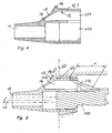
- Figur 5:
- einen Schnitt durch das Gehäuse mit konfektioniertem Steckerkörper;
- Figur 6:
- eine typische Ausbildung eines Kabelendes.
- In den
Figuren 1 bis 5 ist ein Gehäuse (in zwei Ausführungsformen) für Steckverbinderanordnungen für ein elektrisches oder ein optisches Kabel dargestellt. Eine komplette Anordnung umfasst einen als Buchse oder als Stecker ausgebildeten Verbinderkörper 110. Die Oberfläche eines Verbinderkörpers ist in der Regel metallisch ausgebildet oder besteht aus einer Metallschale, wodurch eine leitende, potentialfreie Verbindung zwischen Stecker und Buchse herstellbar ist. - In
Fig. 5 ist schematisch eine konfektionierte Verbinderanordnung gezeigt, die in ein Gerät eingesteckt ist. Als "Gerät" soll hier ein Gerät jeder Art verstanden werden, also beispielsweise eine Leiterplatte, ein Kabelkanal, ein Telefon und/oder ein elektronisches Gerät. Von dem Gerät ist die Gerätekante oder -oberfläche 60 und die Einführöffnung 62 für den Stecker erkennbar. Etwa an der Vorderkante 114 des Verbinderkörpers 110 ist die Riegelzunge 112 angelenkt. InFig. 5 ist besonders auch erkennbar, dass die Länge L der Riegelzunge 112 nicht länger ist als die Tiefe der Stecköffnung 62. Die Riegelzunge ist in ihrer entspannten Lage gezeichnet, so wie sie stünde, wenn kein Verbinderkörper 110 gesteckt wäre. Es ist einsichtig, dass nach dem Stecken des Verbinderkörpers 110 die Riegelzunge vom noch zu beschreibenden Element 12.1 niedergedrückt wird. - Nicht dargestellt in den Figuren sind Mittel zur Konfektionierung des Verbinderkörpers mit einem Kabel. Die Konfektionierung kann beispielsweise per Crimpung erfolgen und zur Befestigung mit einem Gerät kann eine beispielsweise Steckerbuchse aufgebracht werden.
- Die Steckverbinderanordnung hat in den dargestellten Ausführungen einen rechteckigen Querschnitt. Die Anordnung kann aber ebenso für Stecker mit rundem Querschnitt ausgebildet sein. Die vorgeschlagen Anordnung hat ein aus Isoliermaterial bestehendes Gehäuse 100 für den Verbinderkörper 110. Das Isoliermaterial kann ein gummielastischer Kunststoff sein. An der Vorderkante 114 des Verbinderkörpers 110 befindet sich angelenkt und in Richtung entgegen der Steckrichtung beweglich eine Riegelzunge 112, die der Blockierung des Lösens des Verbinderkörpers 110 aus einem als Stecker oder als Buchse ausgebildeten zum Verbinderkörper 110 komplementären Gegenkörper 120 dient. Die Länge L der Riegelzunge ist derart bemessen ist, dass diese nicht länger ist als die Tiefe der Stecköffnung. Am Gehäuse 100 ist ein federndes Betätigungselement 12 zur Betätigung der Riegelzunge 112 angeordnet. Das Betätigungselement hat einen besonders langen Hebelarm, wodurch das Hinunterdrücken der Riegelzunge 112 sehr erleichtert wird.
- Das Element 12 ist am Gehäuse 100 einstückig und mit diesem deformierbar ausgebildet.
- Das Betätigungselement 12 besteht aus einer Anlenkstelle 16, einem als Griffwulst ausgebildeten Druck-Teil 14 (zur manuellen Betätigung zum Lösen der mechanischen Verriegelung) und aus einem parallel zur Einsteckrichtung ausgebildeten Druckkörper 12.1.
- Die genannten Teile des Betätigungselements 12 sind einstückig mit dem Gehäuse ausgebildet und somit quasi in der Gehäusewandung integriert. Die Anlenkstelle 16 (als Wurzel des Stegs 15) liegt nahe der Kabeleinführöffnung 11. Zwischen Anlenkstelle 16 und dem als Griffwulst ausgebildeten Druck-Teil 14 ist ein schräg ansteigender Steg 15 vorhanden, der zur Auflage eines Fingers.eines Benutzers bei der Entriegelung dient (siehe
Fig. 2 ). Steg 15, Griffwulst 14 und der Druckkörper 12.1 liegen in einer Linie und bilden eine relativ starre Einheit. Die Elastizität und Beweglichkeit dieser Einheit kommt durch die als Filmscharnier ausgebildete Anlenkstelle 16 zustande. Unterstützt wird die Beweglichkeit durch die Verringerung der Materialdicke der beiderseitigen Flächenelemente 17. - Die beiden dargestellten Ausführungsformen unterscheiden sich dadurch, dass gemäß
Fig. 1 die beiderseitigen Flächenelemente 17 in dem Gehäuse allseitig geschlossen sind und gemäßFig. 3 die Flächenelemente 17 eine Durchbrechung aufweisen. Beide Ausführungsformen müssen sich in ihrer Flexibilität nicht unbedingt unterscheiden, wenn die Steifigkeit des Materials des Gehäuses und die Materialdicke der Flächenelemente 17 je nach Anwendungsfall unterschiedlich ausgebildet werden. - Flächenelemente 17 sind beiderseits des Einführschachts 104 für die Riegelzunge 112 vorhanden und bilden deren Außenfläche. Wie schon erwähnt, ist das Flächenelement 17 auf beiden Seiten im Gehäuse 100 mit verringerter Materialwanddicke ausgebildet.
- In der nicht allseitig geschlossenen Form des Flächenelements 17 ist ein Durchbruch 105 vorhanden, allerdings ist das Gehäuse 100 im Innern des Durchbruchs geschlossen. Dort ist der Verbinderkörper 110 abgedeckt. Hierdurch bleibt der Verbinderanordnung eine hohe Isolierfestigkeit erhalten. Auch IP-Schutzanforderungen sind erfüllt, weil kein Fenster vorhanden ist, durch welches die Oberfläche des Verbinderkörpers 110 zugänglich ist.
- Die vorliegende Erfindung ist nicht auf die vorstehend beschriebenen Ausführungsformen beschränkt, sondern umfasst auch alle im Sinne der Erfindung möglichen Ausgestaltungen. Diese können sich in der Querschnittsform der Steckverbinderanordnung unterscheiden, also nicht auf Steckertypen wir RJ45 oder RJ11 beschränkt. Ebenso ist die vorgeschlagene Anordnung anwendbar für optische als auch für elektrische Stecker.
Claims (3)
- Steckverbinderanordnung für ein elektrisches oder optisches Kabel, umfassend- einen als Buchse oder als Stecker ausgebildeten Verbinderkörper (110) mit Mitteln zur Konfektionierung mit dem Kabel (10),- ein aus Isoliermaterial bestehendes Gehäuse (100) für den Verbinderkörper (110),- eine an der Vorderkante (114) des Verbinderkörpers (110) angelenkte Riegelzunge (112), die der Blockierung des Lösens des Verbinderkörpers (110) aus einem als Stecker oder als Buchse ausgebildeten zum Verbinderkörper (110) komplementären Gegenkörper (120) dient, wobei- die Länge (L) der Riegelzunge derart bemessen ist, dass diese nicht länger ist als die Tiefe einer im Gegenkörper ausgebildeten Stecköffnung (62),- am Gehäuse (100) ein federndes Element (12) zur Betätigung der Riegelzunge (112) angeordnet ist,- das Betätigungselement (12) am Gehäuse (100) einstückig und mit diesem deformierbar ausgebildet ist,- das Betätigungselement (12) an einem Filmscharnier (16) am Gehäuse angelenkt ist und aus einem parallel zur Einsteckrichtung ausgebildeten starren Druckkörper (12.1) besteht,- wobei das Betätigungselement (12) über mindestens ein im Gehäuse (100) ausgebildetes Flächenelement (17) in der Gehäusewandung integriert ist,dadurch gekennzeichnet, dass
das mindestens eine Flächenelement (17) die Außenfläche des Einführschachts (104) für die Riegelzunge (112) bildet. - Steckverbinderanordnung nach Anspruch 1, dadurch gekennzeichnet, dass das mindestens eine Flächenelement (17) im Gehäuse (100) mit verringerter Materialwanddicke ausgebildet ist.
- Steckverbinderanordnung nach Anspruch 1, dadurch gekennzeichnet, dass das mindestens eine Flächenelement (17) einen Durchbruch (105) aufweist, und dass das Gehäuse (100) innerhalb des Durchbruchs den Verbinderkörper (110) abdeckend ausgebildet ist.
Applications Claiming Priority (2)
| Application Number | Priority Date | Filing Date | Title |
|---|---|---|---|
| DE102006012762A DE102006012762A1 (de) | 2006-03-17 | 2006-03-17 | Steckverbinderanordnung für ein elektrisches oder optisches Kabel |
| PCT/EP2007/001883 WO2007107233A2 (de) | 2006-03-17 | 2007-03-06 | Steckverbinderanordnung für ein elektrisches oder optisches kabel |
Publications (2)
| Publication Number | Publication Date |
|---|---|
| EP1997192A2 EP1997192A2 (de) | 2008-12-03 |
| EP1997192B1 true EP1997192B1 (de) | 2009-09-30 |
Family
ID=38001739
Family Applications (1)
| Application Number | Title | Priority Date | Filing Date |
|---|---|---|---|
| EP07711793A Not-in-force EP1997192B1 (de) | 2006-03-17 | 2007-03-06 | Steckverbinderanordnung für ein elektrisches oder optisches kabel |
Country Status (6)
| Country | Link |
|---|---|
| US (1) | US7824205B2 (de) |
| EP (1) | EP1997192B1 (de) |
| AT (1) | ATE444579T1 (de) |
| CA (1) | CA2645111C (de) |
| DE (2) | DE102006012762A1 (de) |
| WO (1) | WO2007107233A2 (de) |
Families Citing this family (9)
| Publication number | Priority date | Publication date | Assignee | Title |
|---|---|---|---|---|
| CN102201631A (zh) * | 2010-03-26 | 2011-09-28 | 富士康(昆山)电脑接插件有限公司 | 电连接器组件 |
| CN102544903A (zh) * | 2010-12-28 | 2012-07-04 | 鸿富锦精密工业(深圳)有限公司 | 水晶头拔出辅助装置及水晶头组合 |
| DE202011005209U1 (de) | 2011-04-13 | 2012-07-16 | Wieland Electric Gmbh | Stecker- oder Buchsenkontakt |
| DE102012100235B4 (de) * | 2012-01-12 | 2015-12-24 | Phoenix Contact Gmbh & Co. Kg | Kabelstecker mit Abdeckeinrichtung |
| DE102012202225B4 (de) * | 2012-02-14 | 2015-10-22 | Te Connectivity Germany Gmbh | Steckergehäuse mit Dichtung |
| US8899845B2 (en) | 2012-05-15 | 2014-12-02 | Panduit Corp. | Fiber optic connector |
| CN105720392B (zh) | 2014-12-01 | 2019-06-28 | 康宁研究与开发公司 | 可升级配线架和线缆连接器以及布线管理系统 |
| US11165184B2 (en) * | 2019-02-15 | 2021-11-02 | The Dogoldogol Family Trust | Orientation device |
| CN115249901B (zh) * | 2021-12-28 | 2023-04-07 | 深圳市锦凌电子有限公司 | 一种5g通信集束连接器 |
Family Cites Families (12)
| Publication number | Priority date | Publication date | Assignee | Title |
|---|---|---|---|---|
| FR2443147A1 (fr) | 1978-11-30 | 1980-06-27 | Cit Alcatel | Dispositif de raccordement electrique |
| JP2864954B2 (ja) | 1993-07-28 | 1999-03-08 | 住友電装株式会社 | コネクタ |
| US5462457A (en) * | 1994-09-22 | 1995-10-31 | The Whitaker Corporation | Overmold strain relief and snag prevention feature |
| US5638474A (en) * | 1995-08-30 | 1997-06-10 | Lucent Technologies Inc. | Anti-snag latch assembly for a connector |
| US5685736A (en) * | 1996-04-08 | 1997-11-11 | Lung; Nu | Connector jacket |
| US6322386B1 (en) * | 2000-09-12 | 2001-11-27 | The Jpm Company | Connector boot with integral latch release |
| US7063554B2 (en) * | 2003-01-09 | 2006-06-20 | International Business Machines Corporation | Modular connector anti-snag retrofit |
| DE202004019870U1 (de) * | 2004-12-17 | 2005-02-24 | Kovacs, Tibor | Stecker für Datenkabel |
| US7101212B1 (en) * | 2005-03-07 | 2006-09-05 | Kevin Larkin | Snagless plug and boot connection |
| US7329137B2 (en) * | 2005-10-05 | 2008-02-12 | Tyco Electronics Corporation | Modular plug with slider latch |
| US7431604B2 (en) * | 2005-10-19 | 2008-10-07 | Tmb | Clamshell style holding part |
| US7354291B2 (en) * | 2006-03-01 | 2008-04-08 | Panduit Corp. | Plug locking assembly |
-
2006
- 2006-03-17 DE DE102006012762A patent/DE102006012762A1/de not_active Withdrawn
-
2007
- 2007-03-06 EP EP07711793A patent/EP1997192B1/de not_active Not-in-force
- 2007-03-06 US US12/293,406 patent/US7824205B2/en not_active Expired - Fee Related
- 2007-03-06 WO PCT/EP2007/001883 patent/WO2007107233A2/de not_active Ceased
- 2007-03-06 AT AT07711793T patent/ATE444579T1/de active
- 2007-03-06 DE DE502007001636T patent/DE502007001636D1/de active Active
- 2007-03-06 CA CA2645111A patent/CA2645111C/en not_active Expired - Fee Related
Also Published As
| Publication number | Publication date |
|---|---|
| DE502007001636D1 (de) | 2009-11-12 |
| ATE444579T1 (de) | 2009-10-15 |
| CA2645111A1 (en) | 2007-09-27 |
| US7824205B2 (en) | 2010-11-02 |
| CA2645111C (en) | 2011-01-25 |
| EP1997192A2 (de) | 2008-12-03 |
| DE102006012762A1 (de) | 2007-09-27 |
| US20090298350A1 (en) | 2009-12-03 |
| WO2007107233A2 (de) | 2007-09-27 |
| WO2007107233A3 (de) | 2007-11-08 |
Similar Documents
| Publication | Publication Date | Title |
|---|---|---|
| EP1997192B1 (de) | Steckverbinderanordnung für ein elektrisches oder optisches kabel | |
| DE102004038123B4 (de) | Elektrischer Stecker und elektrische Steckeraufnahme | |
| DE69420382T2 (de) | Elektrischer kabelverbinder | |
| DE3514097A1 (de) | Verbindungsklemme fuer elektrische leiter | |
| DE2134319A1 (de) | Verbinderanordnung aus dem Leiter eines Flachkabels und einem elektrischen Verbinder | |
| DE102010014143A1 (de) | Betätigungseinrichtung für eine elektrische Anschlussklemme | |
| EP2807709B1 (de) | Mehradriges kabel mit anschlusskomponente | |
| AT503089A2 (de) | Aufsatzteil | |
| DE102014115595B3 (de) | Stecker und Gegenstecker | |
| EP2580823A1 (de) | Anbausteckverbinder | |
| EP2147483A2 (de) | Elektrischer verbinder mit einer staubabdeckung | |
| WO2014117926A1 (de) | Steckverbinder | |
| EP4500637A1 (de) | Erdungsmodul zur aufnahme in einen metallischen steckverbindermodularrahmen und zur erdung desselben | |
| DE102021129010A1 (de) | Kontaktträgereinrichtung, Anschlussvorrichtung, Betätiger, Steckverbindereinsatz und Montageverfahren sowie Kabelanschlusssystem | |
| EP1282203A2 (de) | Elektrischer Steckverbinder | |
| DE102004022345B4 (de) | Elektrische Steckverbindervorrichtung | |
| DE202005007221U1 (de) | Befestigungseinsatz für einen Steckverbinder | |
| DE102018126141A1 (de) | Anordnung mit einer Leiterplatten-Anschlussvorrichtung | |
| EP1502324A1 (de) | Steckerbr cke mit hohlstift | |
| DE3941398A1 (de) | Adapter fuer fernmeldetechnische geraete | |
| DE19729800A1 (de) | Stecker oder Dose für Steckverbinder | |
| DE102017102241B4 (de) | Steckdosenerweiterung | |
| DE2803359C2 (de) | Gerätesteckdose | |
| DE19518828A1 (de) | Flachsteckhülse | |
| DE19614453A1 (de) | Steckbuchseneinsatz beziehungsweise Steckdose |
Legal Events
| Date | Code | Title | Description |
|---|---|---|---|
| PUAI | Public reference made under article 153(3) epc to a published international application that has entered the european phase |
Free format text: ORIGINAL CODE: 0009012 |
|
| 17P | Request for examination filed |
Effective date: 20080911 |
|
| AK | Designated contracting states |
Kind code of ref document: A2 Designated state(s): AT BE BG CH CY CZ DE DK EE ES FI FR GB GR HU IE IS IT LI LT LU LV MC MT NL PL PT RO SE SI SK TR |
|
| 17Q | First examination report despatched |
Effective date: 20090122 |
|
| GRAP | Despatch of communication of intention to grant a patent |
Free format text: ORIGINAL CODE: EPIDOSNIGR1 |
|
| GRAS | Grant fee paid |
Free format text: ORIGINAL CODE: EPIDOSNIGR3 |
|
| GRAA | (expected) grant |
Free format text: ORIGINAL CODE: 0009210 |
|
| AK | Designated contracting states |
Kind code of ref document: B1 Designated state(s): AT BE BG CH CY CZ DE DK EE ES FI FR GB GR HU IE IS IT LI LT LU LV MC MT NL PL PT RO SE SI SK TR |
|
| REG | Reference to a national code |
Ref country code: CH Ref legal event code: EP Ref country code: GB Ref legal event code: FG4D Free format text: NOT ENGLISH |
|
| REG | Reference to a national code |
Ref country code: IE Ref legal event code: FG4D |
|
| REF | Corresponds to: |
Ref document number: 502007001636 Country of ref document: DE Date of ref document: 20091112 Kind code of ref document: P |
|
| PG25 | Lapsed in a contracting state [announced via postgrant information from national office to epo] |
Ref country code: SE Free format text: LAPSE BECAUSE OF FAILURE TO SUBMIT A TRANSLATION OF THE DESCRIPTION OR TO PAY THE FEE WITHIN THE PRESCRIBED TIME-LIMIT Effective date: 20090930 Ref country code: LT Free format text: LAPSE BECAUSE OF FAILURE TO SUBMIT A TRANSLATION OF THE DESCRIPTION OR TO PAY THE FEE WITHIN THE PRESCRIBED TIME-LIMIT Effective date: 20090930 Ref country code: FI Free format text: LAPSE BECAUSE OF FAILURE TO SUBMIT A TRANSLATION OF THE DESCRIPTION OR TO PAY THE FEE WITHIN THE PRESCRIBED TIME-LIMIT Effective date: 20090930 |
|
| LTIE | Lt: invalidation of european patent or patent extension |
Effective date: 20090930 |
|
| PG25 | Lapsed in a contracting state [announced via postgrant information from national office to epo] |
Ref country code: LV Free format text: LAPSE BECAUSE OF FAILURE TO SUBMIT A TRANSLATION OF THE DESCRIPTION OR TO PAY THE FEE WITHIN THE PRESCRIBED TIME-LIMIT Effective date: 20090930 Ref country code: SI Free format text: LAPSE BECAUSE OF FAILURE TO SUBMIT A TRANSLATION OF THE DESCRIPTION OR TO PAY THE FEE WITHIN THE PRESCRIBED TIME-LIMIT Effective date: 20090930 Ref country code: PL Free format text: LAPSE BECAUSE OF FAILURE TO SUBMIT A TRANSLATION OF THE DESCRIPTION OR TO PAY THE FEE WITHIN THE PRESCRIBED TIME-LIMIT Effective date: 20090930 |
|
| NLV1 | Nl: lapsed or annulled due to failure to fulfill the requirements of art. 29p and 29m of the patents act | ||
| PG25 | Lapsed in a contracting state [announced via postgrant information from national office to epo] |
Ref country code: RO Free format text: LAPSE BECAUSE OF FAILURE TO SUBMIT A TRANSLATION OF THE DESCRIPTION OR TO PAY THE FEE WITHIN THE PRESCRIBED TIME-LIMIT Effective date: 20090930 Ref country code: PT Free format text: LAPSE BECAUSE OF FAILURE TO SUBMIT A TRANSLATION OF THE DESCRIPTION OR TO PAY THE FEE WITHIN THE PRESCRIBED TIME-LIMIT Effective date: 20100201 Ref country code: IS Free format text: LAPSE BECAUSE OF FAILURE TO SUBMIT A TRANSLATION OF THE DESCRIPTION OR TO PAY THE FEE WITHIN THE PRESCRIBED TIME-LIMIT Effective date: 20100130 Ref country code: CZ Free format text: LAPSE BECAUSE OF FAILURE TO SUBMIT A TRANSLATION OF THE DESCRIPTION OR TO PAY THE FEE WITHIN THE PRESCRIBED TIME-LIMIT Effective date: 20090930 Ref country code: ES Free format text: LAPSE BECAUSE OF FAILURE TO SUBMIT A TRANSLATION OF THE DESCRIPTION OR TO PAY THE FEE WITHIN THE PRESCRIBED TIME-LIMIT Effective date: 20100110 Ref country code: EE Free format text: LAPSE BECAUSE OF FAILURE TO SUBMIT A TRANSLATION OF THE DESCRIPTION OR TO PAY THE FEE WITHIN THE PRESCRIBED TIME-LIMIT Effective date: 20090930 |
|
| RAP2 | Party data changed (patent owner data changed or rights of a patent transferred) |
Owner name: EATON INDUSTIES GMBH |
|
| REG | Reference to a national code |
Ref country code: IE Ref legal event code: FD4D |
|
| PG25 | Lapsed in a contracting state [announced via postgrant information from national office to epo] |
Ref country code: SK Free format text: LAPSE BECAUSE OF FAILURE TO SUBMIT A TRANSLATION OF THE DESCRIPTION OR TO PAY THE FEE WITHIN THE PRESCRIBED TIME-LIMIT Effective date: 20090930 |
|
| RAP2 | Party data changed (patent owner data changed or rights of a patent transferred) |
Owner name: EATON INDUSTRIES GMBH |
|
| PG25 | Lapsed in a contracting state [announced via postgrant information from national office to epo] |
Ref country code: DK Free format text: LAPSE BECAUSE OF FAILURE TO SUBMIT A TRANSLATION OF THE DESCRIPTION OR TO PAY THE FEE WITHIN THE PRESCRIBED TIME-LIMIT Effective date: 20090930 Ref country code: IE Free format text: LAPSE BECAUSE OF FAILURE TO SUBMIT A TRANSLATION OF THE DESCRIPTION OR TO PAY THE FEE WITHIN THE PRESCRIBED TIME-LIMIT Effective date: 20090930 Ref country code: NL Free format text: LAPSE BECAUSE OF FAILURE TO SUBMIT A TRANSLATION OF THE DESCRIPTION OR TO PAY THE FEE WITHIN THE PRESCRIBED TIME-LIMIT Effective date: 20090930 |
|
| PLBE | No opposition filed within time limit |
Free format text: ORIGINAL CODE: 0009261 |
|
| STAA | Information on the status of an ep patent application or granted ep patent |
Free format text: STATUS: NO OPPOSITION FILED WITHIN TIME LIMIT |
|
| 26N | No opposition filed |
Effective date: 20100701 |
|
| BERE | Be: lapsed |
Owner name: MOELLER G.M.B.H. Effective date: 20100331 |
|
| PG25 | Lapsed in a contracting state [announced via postgrant information from national office to epo] |
Ref country code: MC Free format text: LAPSE BECAUSE OF NON-PAYMENT OF DUE FEES Effective date: 20100331 Ref country code: GR Free format text: LAPSE BECAUSE OF FAILURE TO SUBMIT A TRANSLATION OF THE DESCRIPTION OR TO PAY THE FEE WITHIN THE PRESCRIBED TIME-LIMIT Effective date: 20091231 |
|
| PG25 | Lapsed in a contracting state [announced via postgrant information from national office to epo] |
Ref country code: BE Free format text: LAPSE BECAUSE OF NON-PAYMENT OF DUE FEES Effective date: 20100331 |
|
| PG25 | Lapsed in a contracting state [announced via postgrant information from national office to epo] |
Ref country code: IT Free format text: LAPSE BECAUSE OF FAILURE TO SUBMIT A TRANSLATION OF THE DESCRIPTION OR TO PAY THE FEE WITHIN THE PRESCRIBED TIME-LIMIT Effective date: 20090930 |
|
| PG25 | Lapsed in a contracting state [announced via postgrant information from national office to epo] |
Ref country code: MT Free format text: LAPSE BECAUSE OF FAILURE TO SUBMIT A TRANSLATION OF THE DESCRIPTION OR TO PAY THE FEE WITHIN THE PRESCRIBED TIME-LIMIT Effective date: 20090930 |
|
| REG | Reference to a national code |
Ref country code: CH Ref legal event code: PL |
|
| GBPC | Gb: european patent ceased through non-payment of renewal fee |
Effective date: 20110306 |
|
| PG25 | Lapsed in a contracting state [announced via postgrant information from national office to epo] |
Ref country code: CH Free format text: LAPSE BECAUSE OF NON-PAYMENT OF DUE FEES Effective date: 20110331 Ref country code: LI Free format text: LAPSE BECAUSE OF NON-PAYMENT OF DUE FEES Effective date: 20110331 |
|
| PG25 | Lapsed in a contracting state [announced via postgrant information from national office to epo] |
Ref country code: GB Free format text: LAPSE BECAUSE OF NON-PAYMENT OF DUE FEES Effective date: 20110306 |
|
| PG25 | Lapsed in a contracting state [announced via postgrant information from national office to epo] |
Ref country code: CY Free format text: LAPSE BECAUSE OF FAILURE TO SUBMIT A TRANSLATION OF THE DESCRIPTION OR TO PAY THE FEE WITHIN THE PRESCRIBED TIME-LIMIT Effective date: 20090930 |
|
| PG25 | Lapsed in a contracting state [announced via postgrant information from national office to epo] |
Ref country code: HU Free format text: LAPSE BECAUSE OF FAILURE TO SUBMIT A TRANSLATION OF THE DESCRIPTION OR TO PAY THE FEE WITHIN THE PRESCRIBED TIME-LIMIT Effective date: 20100401 Ref country code: BG Free format text: LAPSE BECAUSE OF FAILURE TO SUBMIT A TRANSLATION OF THE DESCRIPTION OR TO PAY THE FEE WITHIN THE PRESCRIBED TIME-LIMIT Effective date: 20090930 Ref country code: LU Free format text: LAPSE BECAUSE OF NON-PAYMENT OF DUE FEES Effective date: 20100306 |
|
| PG25 | Lapsed in a contracting state [announced via postgrant information from national office to epo] |
Ref country code: TR Free format text: LAPSE BECAUSE OF FAILURE TO SUBMIT A TRANSLATION OF THE DESCRIPTION OR TO PAY THE FEE WITHIN THE PRESCRIBED TIME-LIMIT Effective date: 20090930 |
|
| REG | Reference to a national code |
Ref country code: AT Ref legal event code: MM01 Ref document number: 444579 Country of ref document: AT Kind code of ref document: T Effective date: 20120306 |
|
| PG25 | Lapsed in a contracting state [announced via postgrant information from national office to epo] |
Ref country code: AT Free format text: LAPSE BECAUSE OF NON-PAYMENT OF DUE FEES Effective date: 20120306 |
|
| REG | Reference to a national code |
Ref country code: FR Ref legal event code: PLFP Year of fee payment: 10 |
|
| REG | Reference to a national code |
Ref country code: FR Ref legal event code: PLFP Year of fee payment: 11 |
|
| PGFP | Annual fee paid to national office [announced via postgrant information from national office to epo] |
Ref country code: FR Payment date: 20170222 Year of fee payment: 11 |
|
| PGFP | Annual fee paid to national office [announced via postgrant information from national office to epo] |
Ref country code: DE Payment date: 20170331 Year of fee payment: 11 |
|
| REG | Reference to a national code |
Ref country code: DE Ref legal event code: R119 Ref document number: 502007001636 Country of ref document: DE |
|
| PG25 | Lapsed in a contracting state [announced via postgrant information from national office to epo] |
Ref country code: DE Free format text: LAPSE BECAUSE OF NON-PAYMENT OF DUE FEES Effective date: 20181002 |
|
| PG25 | Lapsed in a contracting state [announced via postgrant information from national office to epo] |
Ref country code: FR Free format text: LAPSE BECAUSE OF NON-PAYMENT OF DUE FEES Effective date: 20180331 |