EP0637102A1 - Method and apparatus for visibly indicating a properly fitted connector - Google Patents
Method and apparatus for visibly indicating a properly fitted connector Download PDFInfo
- Publication number
- EP0637102A1 EP0637102A1 EP94111789A EP94111789A EP0637102A1 EP 0637102 A1 EP0637102 A1 EP 0637102A1 EP 94111789 A EP94111789 A EP 94111789A EP 94111789 A EP94111789 A EP 94111789A EP 0637102 A1 EP0637102 A1 EP 0637102A1
- Authority
- EP
- European Patent Office
- Prior art keywords
- cover
- connector
- housing
- engagement
- lockarm
- Prior art date
- Legal status (The legal status is an assumption and is not a legal conclusion. Google has not performed a legal analysis and makes no representation as to the accuracy of the status listed.)
- Granted
Links
- 238000000034 method Methods 0.000 title claims description 9
- 238000001514 detection method Methods 0.000 claims abstract description 23
- 230000013011 mating Effects 0.000 claims description 15
- 230000002452 interceptive effect Effects 0.000 claims description 2
- 238000010276 construction Methods 0.000 description 9
- 230000000717 retained effect Effects 0.000 description 2
- 229920003002 synthetic resin Polymers 0.000 description 2
- 239000000057 synthetic resin Substances 0.000 description 2
- 230000003247 decreasing effect Effects 0.000 description 1
- 238000004519 manufacturing process Methods 0.000 description 1
- 238000012986 modification Methods 0.000 description 1
- 230000004048 modification Effects 0.000 description 1
- 238000000465 moulding Methods 0.000 description 1
- 238000012856 packing Methods 0.000 description 1
Images
Classifications
-
- H—ELECTRICITY
- H01—ELECTRIC ELEMENTS
- H01R—ELECTRICALLY-CONDUCTIVE CONNECTIONS; STRUCTURAL ASSOCIATIONS OF A PLURALITY OF MUTUALLY-INSULATED ELECTRICAL CONNECTING ELEMENTS; COUPLING DEVICES; CURRENT COLLECTORS
- H01R13/00—Details of coupling devices of the kinds covered by groups H01R12/70 or H01R24/00 - H01R33/00
- H01R13/62—Means for facilitating engagement or disengagement of coupling parts or for holding them in engagement
- H01R13/627—Snap or like fastening
- H01R13/6271—Latching means integral with the housing
- H01R13/6272—Latching means integral with the housing comprising a single latching arm
-
- H—ELECTRICITY
- H01—ELECTRIC ELEMENTS
- H01R—ELECTRICALLY-CONDUCTIVE CONNECTIONS; STRUCTURAL ASSOCIATIONS OF A PLURALITY OF MUTUALLY-INSULATED ELECTRICAL CONNECTING ELEMENTS; COUPLING DEVICES; CURRENT COLLECTORS
- H01R13/00—Details of coupling devices of the kinds covered by groups H01R12/70 or H01R24/00 - H01R33/00
- H01R13/64—Means for preventing incorrect coupling
- H01R13/641—Means for preventing incorrect coupling by indicating incorrect coupling; by indicating correct or full engagement
Definitions
- This invention relates to a method of indicating a properly fitted connector and a connector that is releasably fitted on a mating connector and is maintained in engagement with the mating connector by a lock arm. More particularly, this invention relates to a connector having clearly visible structure for indicating whether two housings are completely engaged with each other.
- a lock arm c provided on the housing b is engaged with an engagement portion d provided on the female housing a, so that the two housings a and b are held in an engaged condition.
- a cover f is mounted on an upper surface of the female housing a for pivotal movement about a shaft h, and a detection portion g for abutting against a projection e formed on a rear end of the mole housing b in the fitting direction is mounted on the cover f in a projected manner.
- the cover f is normally held in an upright posture (Fig.
- the detection device of the connector requires many component parts including the cover f, the shaft h, and the torsion coil spring i. Accordingly, the cost for this connector has been greatly increased, and the management of the component parts and the assembling operation have been cumbersome.
- a connector is adapted to be releasably fitted relative to a mating connector.
- the connector comprises a lock arm mounted on a connector housing that is engageable with an engagement portion provided on a housing of the mating connector to hold the two housings in an engaged condition; a cover for covering the lock arm is mounted through a self-hinge portion on the connector housing for pivotal movement between an open position and a closed position; and a non-engagement detection projection for holding the cover in a raised position when the lock arm is not engaged, with the non-engagement detection portion being formed on at least one of the lock arm and the cover.
- the cover can be provided with a retaining portion for being engaged with the connector housing to hold the cover in ouch a condition that the cover covers the lock arm.
- a connector comprising a housing, a lock arm pivotably engaged with the housing, said lock arm including a hook portion adapted to engage with an engagement portion of a mating connector, a cover pivotably mounted on the housing, and a non-engagement detection projection mounted on at least one of said cover and said lock arm for providing interference between said cover and said lock arm when the connector is not properly fitted with the mating connector.
- a method of connecting first and second connectors and visually indicating a properly connected condition the first connector including a housing having a pivotable cover and a lock arm that includes a hook portion engageable with an engagement portion formed on the second connector, the method comprising the steps of: sliding the first and second connectors together so as to make contact between the hook portion and the engagement portion; pivoting the cover relative to the housing; engaging the cover and the lock arm in an interfering manner to indicate an incomplete connection when the first and second connectors are not fully engaged; and connecting a distal end of the cover with the housing to indicate a complete connection when the first and second covers are fully engaged.
- a connector comprising a housing having a pivotably mounted lock arm and a cover, the lock arm including a hook portion that is engageable with an engagement portion formed on a mating connector, and means for visually indicating an incomplete connection by providing interference between the cover and the lock arm when the connector is not properly fitted with the mating connector.
- the operation of the invention is as follows: After the connector is fitted on the mating connector, the cover is closed to cover the lock arm, and at this time if the lock arm is not engaged with the engagement portion, the non-engagement detection projection, formed on at least one of the lock arm and the cover, functions to hold the cover in a raised condition, that is, a non-fully closed condition, and this visually indicates the fact that the two housings are not completely engaged with each other.
- the retaining portion holds the cover in such a condition that the cover covers the lock arm, if the two housings are in the engaged condition.
- This construction is provided on the connector adapted to be connected to the connector connected to the equipment, and therefore there are achieved advantages that the connector connected to the equipment is not increased in size, and that the construction of the equipment is not limited.
- the cover is held in the condition in which it covers the lock arm, it can be positively confirmed that the detection operation for determining whether or not the two housings are in the engaged condition has been completed.
- a female connector housing 1 is made of a synthetic resin.
- a lock arm 2 having a hook portion 3 at its front end is provided at an upper side of the housing 1 and extends horizontally in a direction of the length of the housing 1, the lock arm 2 being resiliently rockable about a fulcrum 4 formed on a central portion of the lock arm's lower surface in the direction of its length.
- the hook portion 3 of the lock arm 2 is brought into engagement with an engagement portion 6 formed on an upper surface of the male housing 5, and the lock arm 2 is pushed to swing in such a manner that its front end moves upward, and when the hook portion 3 passes past the engagement portion 6, the lock arm 2 is restored into a horizontal posture by its own resilient force. Accordingly, the hook portion 3 is retained on the engagement portion 6, thereby holding the two housings 1 and 5 in an engaged condition against withdrawal.
- a cover 8 is pivotally mounted on the upper surface of the female housing 1 by a self hinge portion 10 so as to cover the upper surface of the lock arm 2, the cover 8 having side plates 9 disposed respectively on right and left sides of the rear end portion of the lock arm.
- the cover In the molding of the female housing, the cover is disposed in an open position, that is, perpendicular to this housing.
- a non-engagement detection projection 11 is formed on a back surface of the cover 8 at a proximal end portion thereof registrable with the front end portion of the lock arm 2.
- a pawl 13 is formed on each of the right and left side plates 9 of the cover 8, and a retaining hole 15 is formed through each of right and left aide walls 14 of the housing 1.
- the cover 8 is closed to be disposed in a horizontal posture, the pawls 13 are engaged in the retaining holes 15, respectively.
- Male terminals 16 are provided in the male connector housing 5 as shown in Fig. 2, and female terminals (not shown) for receiving the male terminals 16 are provided in the female housing 1.
- a waterproof packing 17 for fitting in the male housing 5 is provided in the female housing 1.
- This embodiment has the above construction, and its operation will now be described.
- the female housing 1 is fitted on the male housing 5 as described above, and the cover 8 is pushed down by a user's finger F from its open position toward its closed position as shown in Fig. 3(A).
- the lock arm 2 is slanting forwardly upwardly with the hook portion 3 placed on the engagement portion 6, as shown in Fig. 3(A). Therefore, the non-engagement detection projection 11 of the cover 8 is engaged with the upper surface of the lock arm 2 at its front end portion, so that the cover 8 is held in a raised condition, and hence can not be fully closed.
- the lock arm 2 When the two housings 1 and 5 are completely engaged with each other either by thus pushing the female housing 1 again or by the first fitting operation, the lock arm 2 is disposed in a horizontal posture with its hook portion 3 retained on the engagement portion 6 as shown in Fig. 3(B), and therefore the cover 8 can be fully closed without abutment of the non-engagement detection projection 11 against the lock arm 2, and from this condition, the engaged condition of the two housings 1 and 5 is detected.
- the pawls 13 of the side plates 9 of the cover 8 are fitted respectively in the retaining holes 15 in the side walls 14 of the housing 1, thereby holding the cover in its closed position, and it can be confirmed from this that the detection operation for determining whether or not the two housings 1 and 5 are in the engaged condition has been completed.
- the cover 8 by merely closing the cover 8, it can be easily judged whether or not the two housings 1 and 5 have been brought into engagement with each other. Moreover, because the cover 8 is integrally mounted on the housing 1 through the self hinge portion 10, the number of the component parts is not increased, thus preventing the cost from being increased, and extra management of the component parts and extra assembling operations can be eliminated.
- the cover 8 is provided not on the connector connected to the equipment, but on the connector for fitting on the equipment-side connector, the construction of the equipment is not limited, and this construction is suited for a connector to be fitted on a connector integrally incorporated, for example, in a relay.
- the provision of the non-engagement detection projection 11 is not limited to the back surface position of the cover 8 in the above embodiment, and the projection may be provided at a position on the upper surface of the lock arm 2, or may be formed on each of the cover and the lock arm.
Landscapes
- Details Of Connecting Devices For Male And Female Coupling (AREA)
Abstract
Description
- This invention relates to a method of indicating a properly fitted connector and a connector that is releasably fitted on a mating connector and is maintained in engagement with the mating connector by a lock arm. More particularly, this invention relates to a connector having clearly visible structure for indicating whether two housings are completely engaged with each other.
- One known connector having such an indicator is disclosed in Japanese Utility Model Unexamined Publication No. 2-50981.
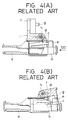
- In this connector, when a male connector housing b is fitted in a female connector housing a, which is connected to equipment (not shown) in a direction of an
arrow 100 as shown Fig. 4(A), a lock arm c provided on the housing b is engaged with an engagement portion d provided on the female housing a, so that the two housings a and b are held in an engaged condition. A cover f is mounted on an upper surface of the female housing a for pivotal movement about a shaft h, and a detection portion g for abutting against a projection e formed on a rear end of the mole housing b in the fitting direction is mounted on the cover f in a projected manner. The cover f is normally held in an upright posture (Fig. 4(A)) by a resilient force of a torsion coil spring i. In a non-engaged condition of the two housings a and b as shown in Fig. 4(B), when the cover f is pushed down after the male housing b is fitted, the detection portion g on the cover f abuts against the projection e on the male housing b, thereby detecting the fact that the two housings a and b are not engaged with each other. - However, in addition to the housing a, the detection device of the connector requires many component parts including the cover f, the shaft h, and the torsion coil spring i. Accordingly, the cost for this connector has been greatly increased, and the management of the component parts and the assembling operation have been cumbersome.
- Another disadvantage is that because the cover f is mounted on the connector connected to the equipment, the construction of the equipment has been limited. For example, where a connector is integrally mounted on a small device such a relay, the overall size of the device is increased because of an increased size of the connector portion.
- The present invention has been made in view of the above problems. In a first aspect of the invention, a connector is adapted to be releasably fitted relative to a mating connector. The connector comprises a lock arm mounted on a connector housing that is engageable with an engagement portion provided on a housing of the mating connector to hold the two housings in an engaged condition; a cover for covering the lock arm is mounted through a self-hinge portion on the connector housing for pivotal movement between an open position and a closed position; and a non-engagement detection projection for holding the cover in a raised position when the lock arm is not engaged, with the non-engagement detection portion being formed on at least one of the lock arm and the cover. The cover can be provided with a retaining portion for being engaged with the connector housing to hold the cover in ouch a condition that the cover covers the lock arm.
- In another aspect of the invention, there is provided a connector comprising a housing, a lock arm pivotably engaged with the housing, said lock arm including a hook portion adapted to engage with an engagement portion of a mating connector, a cover pivotably mounted on the housing, and a non-engagement detection projection mounted on at least one of said cover and said lock arm for providing interference between said cover and said lock arm when the connector is not properly fitted with the mating connector.
- In another aspect of the invention, there is provided a method of connecting first and second connectors and visually indicating a properly connected condition, the first connector including a housing having a pivotable cover and a lock arm that includes a hook portion engageable with an engagement portion formed on the second connector, the method comprising the steps of: sliding the first and second connectors together so as to make contact between the hook portion and the engagement portion; pivoting the cover relative to the housing; engaging the cover and the lock arm in an interfering manner to indicate an incomplete connection when the first and second connectors are not fully engaged; and connecting a distal end of the cover with the housing to indicate a complete connection when the first and second covers are fully engaged.
- In still yet another aspect of the present invention, there is provided a connector comprising a housing having a pivotably mounted lock arm and a cover, the lock arm including a hook portion that is engageable with an engagement portion formed on a mating connector, and means for visually indicating an incomplete connection by providing interference between the cover and the lock arm when the connector is not properly fitted with the mating connector.
- The operation of the invention is as follows: After the connector is fitted on the mating connector, the cover is closed to cover the lock arm, and at this time if the lock arm is not engaged with the engagement portion, the non-engagement detection projection, formed on at least one of the lock arm and the cover, functions to hold the cover in a raised condition, that is, a non-fully closed condition, and this visually indicates the fact that the two housings are not completely engaged with each other. When the cover is closed, the retaining portion holds the cover in such a condition that the cover covers the lock arm, if the two housings are in the engaged condition.
- With this construction, by merely closing the cover, it can be positively and visually judged whether or not the two housings are brought into engagement with each other. Because the cover is integrally mounted on the housing through the self hinge portion, manufacturing costs can be decreased in contrast with the conventional construction in which separate parts are required. In addition, some component parts and assembling operation steps can be eliminated.
- This construction is provided on the connector adapted to be connected to the connector connected to the equipment, and therefore there are achieved advantages that the connector connected to the equipment is not increased in size, and that the construction of the equipment is not limited.
- Because the cover is held in the condition in which it covers the lock arm, it can be positively confirmed that the detection operation for determining whether or not the two housings are in the engaged condition has been completed.
- This invention will be described with reference to the following drawings, wherein:
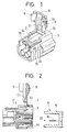
- Fig. 1 is a perspective view of one preferred embodiment of the present invention;
- Fig. 2 is a cross-sectional view of the present invention;
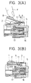
- Figs. 3(A) and 3(B) are illustrations explanatory of the detection operation, Fig. 3(A) being a cross-sectional view showing a non-engaged condition of two housings, and Fig. 3(b) being a cross-sectional view showing an engaged condition of the two housings; and
- Figs. 4(A) and 4(B) are cross-sectional views of a conventional construction.
- One preferred embodiment of the present invention will now be described with reference to Figs. 1 to 3.
- In Figs. 1 and 2, a
female connector housing 1 is made of a synthetic resin. Alock arm 2 having ahook portion 3 at its front end is provided at an upper side of thehousing 1 and extends horizontally in a direction of the length of thehousing 1, thelock arm 2 being resiliently rockable about afulcrum 4 formed on a central portion of the lock arm's lower surface in the direction of its length. When thefemale housing 2 is fitted on amale connector housing 5 of a synthetic resin, which in turn, is connected to equipment, in a direction of anarrow 20 in Fig. 2, thehook portion 3 of thelock arm 2 is brought into engagement with anengagement portion 6 formed on an upper surface of themale housing 5, and thelock arm 2 is pushed to swing in such a manner that its front end moves upward, and when thehook portion 3 passes past theengagement portion 6, thelock arm 2 is restored into a horizontal posture by its own resilient force. Accordingly, thehook portion 3 is retained on theengagement portion 6, thereby holding the twohousings - A
cover 8 is pivotally mounted on the upper surface of thefemale housing 1 by aself hinge portion 10 so as to cover the upper surface of thelock arm 2, thecover 8 havingside plates 9 disposed respectively on right and left sides of the rear end portion of the lock arm. In the molding of the female housing, the cover is disposed in an open position, that is, perpendicular to this housing. Anon-engagement detection projection 11 is formed on a back surface of thecover 8 at a proximal end portion thereof registrable with the front end portion of thelock arm 2. - A
pawl 13 is formed on each of the right andleft side plates 9 of thecover 8, and aretaining hole 15 is formed through each of right andleft aide walls 14 of thehousing 1. When thecover 8 is closed to be disposed in a horizontal posture, thepawls 13 are engaged in theretaining holes 15, respectively. -
Male terminals 16 are provided in themale connector housing 5 as shown in Fig. 2, and female terminals (not shown) for receiving themale terminals 16 are provided in thefemale housing 1. Awaterproof packing 17 for fitting in themale housing 5 is provided in thefemale housing 1. - This embodiment has the above construction, and its operation will now be described.
- The
female housing 1 is fitted on themale housing 5 as described above, and thecover 8 is pushed down by a user's finger F from its open position toward its closed position as shown in Fig. 3(A). At this time, if the twohousings lock arm 2 is slanting forwardly upwardly with thehook portion 3 placed on theengagement portion 6, as shown in Fig. 3(A). Therefore, thenon-engagement detection projection 11 of thecover 8 is engaged with the upper surface of thelock arm 2 at its front end portion, so that thecover 8 is held in a raised condition, and hence can not be fully closed. - Thus, the non-engaged condition of the two
housings female housing 1 to complete the engagement. - When the two
housings female housing 1 again or by the first fitting operation, thelock arm 2 is disposed in a horizontal posture with itshook portion 3 retained on theengagement portion 6 as shown in Fig. 3(B), and therefore thecover 8 can be fully closed without abutment of thenon-engagement detection projection 11 against thelock arm 2, and from this condition, the engaged condition of the twohousings - At this time, the
pawls 13 of theside plates 9 of thecover 8 are fitted respectively in the retainingholes 15 in theside walls 14 of thehousing 1, thereby holding the cover in its closed position, and it can be confirmed from this that the detection operation for determining whether or not the twohousings - Thus, in this embodiment, by merely closing the
cover 8, it can be easily judged whether or not the twohousings cover 8 is integrally mounted on thehousing 1 through theself hinge portion 10, the number of the component parts is not increased, thus preventing the cost from being increased, and extra management of the component parts and extra assembling operations can be eliminated. - Furthermore, because the
cover 8 is provided not on the connector connected to the equipment, but on the connector for fitting on the equipment-side connector, the construction of the equipment is not limited, and this construction is suited for a connector to be fitted on a connector integrally incorporated, for example, in a relay. - Incidentally, the provision of the
non-engagement detection projection 11 is not limited to the back surface position of thecover 8 in the above embodiment, and the projection may be provided at a position on the upper surface of thelock arm 2, or may be formed on each of the cover and the lock arm. - The invention has been described with reference to preferred embodiments thereof, which are intended to be illustrative but not limiting. Various modifications may be made without departing from the spirit and scope of the invention as set forth in the appended claims.
Claims (15)
- A connector adapted to be releasably fitted relative to a mating connector, comprising a connector housing having a lock arm that is engageable with an engagement portion provided on a housing of said mating connector to hold the two housings in an engaged condition; a cover for covering said lock arm mounted through a self-hinge portion on said connector housing for pivotal movement between an open position and a closed position; and a non-engagement detection projection for maintaining said cover in a raised position when said lock arm is not engaged, said non-engagement detection portion being formed on at least one of said lock arm and said cover.
- A connector according to claim 1, wherein said cover is provided with a retaining portion that is engageable with said connector housing to hold said cover in such a condition that said cover covers said lock arm.
- A connector comprising:
a housing;
a lockarm pivotably engaged to said housing, said lockarm including a hook portion adapted to engage with an engagement portion of a mating connector;
a cover pivotably mounted on said housing; and
a non-engagement detection projection mounted on at least one of said cover and said lockarm for providing interference between said cover and said lockarm when the connector is not properly fitted with said mating connector. - The connector of claim 3, wherein said lockarm is pivotably mounted on a fulcrum located on said housing.
- The connector of claim 3, wherein said engagement portion and said non-engagement detection projection each include a first inclined surface and a second surface, and said interference is provided when said inclined surfaces are engaged.
- The connector of claim 5, wherein a fully connected position is achieved when said inclined surfaces disengage and said second surfaces engage, thereby preventing said interference between said cover and said lockarm.
- The connector of claim 3, wherein said non-engagement detector projection is formed on said cover.
- The connector of claim 3, wherein said cover is pivotably connected to said housing with a self-hinge that biases the cover to an open position.
- The connector of claim 3, wherein the cover includes at least one retaining portion having a retaining pawl that is engageable with a retaining hole formed in said housing when said cover and said lockarm do not interfere.
- A method of connecting first and second connectors and visually indicating a properly connected condition, the first connector including a housing having a pivotable cover and lockarm that includes a hook portion engageable with an engagement portion formed on said second connector, said method comprising the steps of:
sliding the first and second connectors together so as to make contact between the hook portion and the engagement portion;
pivoting said cover relative to said housing;
engaging the cover and the lockarm in an interfering manner to indicate an incomplete connection when the first and second connectors are not fully engaged; and
connecting a distal end of the cover with the housing to indicate a complete connection when the first and second connectors are fully engaged. - The method of claim 10, wherein the distal end of the cover includes retaining portions having locking pawls that are engageable with corresponding retaining holes formed in the housing, and the connecting step includes inserting the locking pawls in the retaining holes to maintain the indication of a complete connection.
- The method of claim 10, wherein the pivoting step includes pivoting the cover about a self-hinge member mounted to said housing.
- The method of claim 10, further comprising providing the cover with a non-engagement detection portion and the step of engaging includes engaging the non-engagement detection portion with the hook portion to indicate said incomplete connection.
- A connector comprising a housing having a lockarm and an cover pivotably mounted on the housing, said lockarm including a lock portion that is engageable with an engagement portion formed on a mating connector, and means for indicating an incomplete connection and for providing interference between said cover and said lockarm when the connector is not properly fitted with said mating connector.
- The connector of claim 14, wherein said means includes a non-engagement detection portion formed on at least one of said cover and said lock arm for urging said cover in an open position to indicate said incomplete connection.
Applications Claiming Priority (2)
| Application Number | Priority Date | Filing Date | Title |
|---|---|---|---|
| JP207245/93 | 1993-07-28 | ||
| JP5207245A JP2864954B2 (en) | 1993-07-28 | 1993-07-28 | connector |
Publications (2)
| Publication Number | Publication Date |
|---|---|
| EP0637102A1 true EP0637102A1 (en) | 1995-02-01 |
| EP0637102B1 EP0637102B1 (en) | 1998-04-29 |
Family
ID=16536620
Family Applications (1)
| Application Number | Title | Priority Date | Filing Date |
|---|---|---|---|
| EP94111789A Expired - Lifetime EP0637102B1 (en) | 1993-07-28 | 1994-07-28 | Method and apparatus for visibly indicating a properly fitted connector |
Country Status (4)
| Country | Link |
|---|---|
| US (1) | US5480324A (en) |
| EP (1) | EP0637102B1 (en) |
| JP (1) | JP2864954B2 (en) |
| DE (1) | DE69409882T2 (en) |
Cited By (7)
| Publication number | Priority date | Publication date | Assignee | Title |
|---|---|---|---|---|
| GB2298975B (en) * | 1995-03-15 | 1999-05-12 | Whitaker Corp | Electrical connector housing having protected release mechanism |
| EP0926773A1 (en) * | 1997-12-25 | 1999-06-30 | Sumitomo Wiring Systems, Ltd. | A cover-equipped connector |
| EP0933835A3 (en) * | 1998-02-03 | 1999-08-25 | The Whitaker Corporation | Electrical connector |
| EP0993077A3 (en) * | 1998-10-05 | 2000-07-26 | Yazaki Corporation | Half-fitting prevention connector and method of producing same |
| GB2377092A (en) * | 2001-05-31 | 2002-12-31 | Yazaki Corp | A Mis-alignment or Mis-fitment prevention connector |
| WO2007107233A3 (en) * | 2006-03-17 | 2007-11-08 | Moeller Gmbh | Plug arrangement for an electric or optical cable |
| CN113540883A (en) * | 2021-06-08 | 2021-10-22 | 华为技术有限公司 | Connectors, Adapters, Connector Assemblies and Communication Equipment |
Families Citing this family (20)
| Publication number | Priority date | Publication date | Assignee | Title |
|---|---|---|---|---|
| JP3561959B2 (en) * | 1994-07-13 | 2004-09-08 | 住友電装株式会社 | connector |
| JP3002098B2 (en) * | 1994-10-07 | 2000-01-24 | 矢崎総業株式会社 | Connector assembly method and connector housing |
| GB9508189D0 (en) * | 1995-04-21 | 1995-06-07 | Amp Gmbh | Connector with pivotable coupling lever |
| DE19525257C2 (en) * | 1995-07-11 | 2000-09-07 | Siemens Ag | Electrical plug connection with end position locking |
| US6416700B1 (en) * | 1996-11-27 | 2002-07-09 | Yazaki Corporation | Method of producing resin-molded assembly and method producing double-retaining connector |
| JP3301530B2 (en) * | 1997-02-26 | 2002-07-15 | 住友電装株式会社 | connector |
| JP3457172B2 (en) * | 1998-03-04 | 2003-10-14 | 矢崎総業株式会社 | Connector mating structure |
| JP3609379B2 (en) * | 2002-01-31 | 2005-01-12 | 日本圧着端子製造株式会社 | Electrical connector with locking mechanism |
| US7521039B2 (en) * | 2002-11-08 | 2009-04-21 | Millennium Inorganic Chemicals, Inc. | Photocatalytic rutile titanium dioxide |
| JP4592003B2 (en) * | 2004-12-28 | 2010-12-01 | アライドテレシスホールディングス株式会社 | Connection state maintenance tool |
| JP2009181722A (en) * | 2008-01-29 | 2009-08-13 | Sumitomo Wiring Syst Ltd | Connector |
| FR2960103B1 (en) * | 2010-05-11 | 2013-05-31 | Souriau | CONNECTOR ASSEMBLY FOR LIVE CONNECTION |
| JP5491328B2 (en) * | 2010-09-01 | 2014-05-14 | 株式会社東海理化電機製作所 | Plug lock structure |
| JP5874655B2 (en) * | 2013-01-29 | 2016-03-02 | 住友電装株式会社 | connector |
| KR101830425B1 (en) | 2017-11-02 | 2018-02-20 | 주식회사 경신 | Device for preventing seperation connector |
| KR101830424B1 (en) | 2017-11-02 | 2018-02-20 | 주식회사 경신 | Device for preventing seperation connector |
| KR101830426B1 (en) | 2017-11-02 | 2018-02-20 | 주식회사 경신 | Device for preventing seperation connector |
| KR101830427B1 (en) | 2017-11-02 | 2018-02-20 | 주식회사 경신 | Device for preventing seperation connector |
| KR101830428B1 (en) | 2017-11-02 | 2018-02-20 | 주식회사 경신 | Device for preventing seperation connector |
| DE102017223656A1 (en) * | 2017-12-22 | 2019-06-27 | Bayerische Motoren Werke Aktiengesellschaft | Method for checking connectors |
Citations (1)
| Publication number | Priority date | Publication date | Assignee | Title |
|---|---|---|---|---|
| DE3839728A1 (en) * | 1987-11-25 | 1989-06-08 | Yazaki Corp | CONNECTOR |
Family Cites Families (4)
| Publication number | Priority date | Publication date | Assignee | Title |
|---|---|---|---|---|
| JPS6210885A (en) * | 1985-07-08 | 1987-01-19 | 日本航空電子工業株式会社 | Connector |
| JPH0250981A (en) * | 1988-08-12 | 1990-02-20 | Hitachi Ltd | NaCl corrosion resistant parts, gas turbine blades and gas turbine nozzles |
| GB9012060D0 (en) * | 1990-05-30 | 1990-07-18 | Amp Great Britain | Electrical connector housings |
| JPH05135823A (en) * | 1991-11-11 | 1993-06-01 | Yazaki Corp | Locking device of connector |
-
1993
- 1993-07-28 JP JP5207245A patent/JP2864954B2/en not_active Expired - Lifetime
-
1994
- 1994-07-27 US US08/281,178 patent/US5480324A/en not_active Expired - Fee Related
- 1994-07-28 EP EP94111789A patent/EP0637102B1/en not_active Expired - Lifetime
- 1994-07-28 DE DE69409882T patent/DE69409882T2/en not_active Expired - Fee Related
Patent Citations (1)
| Publication number | Priority date | Publication date | Assignee | Title |
|---|---|---|---|---|
| DE3839728A1 (en) * | 1987-11-25 | 1989-06-08 | Yazaki Corp | CONNECTOR |
Cited By (12)
| Publication number | Priority date | Publication date | Assignee | Title |
|---|---|---|---|---|
| GB2298975B (en) * | 1995-03-15 | 1999-05-12 | Whitaker Corp | Electrical connector housing having protected release mechanism |
| EP0926773A1 (en) * | 1997-12-25 | 1999-06-30 | Sumitomo Wiring Systems, Ltd. | A cover-equipped connector |
| US6135802A (en) * | 1997-12-25 | 2000-10-24 | Sumitomo Wiring Systems, Ltd. | Cover-equipped connector |
| EP0933835A3 (en) * | 1998-02-03 | 1999-08-25 | The Whitaker Corporation | Electrical connector |
| EP0993077A3 (en) * | 1998-10-05 | 2000-07-26 | Yazaki Corporation | Half-fitting prevention connector and method of producing same |
| US6241547B1 (en) | 1998-10-05 | 2001-06-05 | Yazaki Corporation | Half-fitting prevention connector and method of producing same |
| GB2377092A (en) * | 2001-05-31 | 2002-12-31 | Yazaki Corp | A Mis-alignment or Mis-fitment prevention connector |
| GB2377092B (en) * | 2001-05-31 | 2003-09-03 | Yazaki Corp | Connector fitting structure |
| WO2007107233A3 (en) * | 2006-03-17 | 2007-11-08 | Moeller Gmbh | Plug arrangement for an electric or optical cable |
| US7824205B2 (en) | 2006-03-17 | 2010-11-02 | Eaton Industries Gmbh | Plug arrangement for an electric or optical cable |
| CN113540883A (en) * | 2021-06-08 | 2021-10-22 | 华为技术有限公司 | Connectors, Adapters, Connector Assemblies and Communication Equipment |
| WO2022257417A1 (en) * | 2021-06-08 | 2022-12-15 | 华为技术有限公司 | Connector, adapter, connector assembly, and communication device |
Also Published As
| Publication number | Publication date |
|---|---|
| DE69409882D1 (en) | 1998-06-04 |
| JP2864954B2 (en) | 1999-03-08 |
| US5480324A (en) | 1996-01-02 |
| DE69409882T2 (en) | 1998-08-27 |
| JPH0745334A (en) | 1995-02-14 |
| EP0637102B1 (en) | 1998-04-29 |
Similar Documents
| Publication | Publication Date | Title |
|---|---|---|
| US5480324A (en) | Method and apparatus for visibly indicating a properly fitted connector | |
| US5203718A (en) | Connector | |
| US5759058A (en) | Connector position assurance component | |
| US5429527A (en) | Connector | |
| US4714433A (en) | Electrical connector with position assurance and double lock | |
| US4902968A (en) | Connector terminal checking tool | |
| JP2519179Y2 (en) | Double locking structure for terminal fittings in electrical connectors | |
| EP0717465B1 (en) | Electrical connector with position assurance system. | |
| CN101394042B (en) | Connectors, connector assemblies, and methods of connection | |
| JPH0992398A (en) | Electrical connector | |
| JPH0581967U (en) | connector | |
| JPH0718378U (en) | Connector with mating confirmation mechanism | |
| US5320556A (en) | Electrical connector with fitting confirmation mechanism | |
| US5910028A (en) | Connector | |
| JP3561959B2 (en) | connector | |
| JPH09185974A (en) | Connector mating release mechanism | |
| US5707248A (en) | Device for preventing a wrong coupling of a connector | |
| US5163848A (en) | Incomplete fitting prevention connector | |
| JPH07114135B2 (en) | Lock detection mechanism for electrical connectors | |
| US5577014A (en) | Disk cartridge opposite-insertion preventing mechanism | |
| JP2001297827A (en) | Connector | |
| EP1061614A2 (en) | Half-fitting prevention connector | |
| JPH09106852A (en) | Water-proof connector | |
| JP2571978B2 (en) | connector | |
| JP2600862Y2 (en) | Connector half mating detection structure |
Legal Events
| Date | Code | Title | Description |
|---|---|---|---|
| PUAI | Public reference made under article 153(3) epc to a published international application that has entered the european phase |
Free format text: ORIGINAL CODE: 0009012 |
|
| AK | Designated contracting states |
Kind code of ref document: A1 Designated state(s): DE FR GB |
|
| 17P | Request for examination filed |
Effective date: 19950619 |
|
| 17Q | First examination report despatched |
Effective date: 19960226 |
|
| GRAG | Despatch of communication of intention to grant |
Free format text: ORIGINAL CODE: EPIDOS AGRA |
|
| GRAG | Despatch of communication of intention to grant |
Free format text: ORIGINAL CODE: EPIDOS AGRA |
|
| GRAH | Despatch of communication of intention to grant a patent |
Free format text: ORIGINAL CODE: EPIDOS IGRA |
|
| GRAH | Despatch of communication of intention to grant a patent |
Free format text: ORIGINAL CODE: EPIDOS IGRA |
|
| GRAA | (expected) grant |
Free format text: ORIGINAL CODE: 0009210 |
|
| AK | Designated contracting states |
Kind code of ref document: B1 Designated state(s): DE FR GB |
|
| REF | Corresponds to: |
Ref document number: 69409882 Country of ref document: DE Date of ref document: 19980604 |
|
| ET | Fr: translation filed | ||
| PLBE | No opposition filed within time limit |
Free format text: ORIGINAL CODE: 0009261 |
|
| STAA | Information on the status of an ep patent application or granted ep patent |
Free format text: STATUS: NO OPPOSITION FILED WITHIN TIME LIMIT |
|
| 26N | No opposition filed | ||
| REG | Reference to a national code |
Ref country code: GB Ref legal event code: IF02 |
|
| PGFP | Annual fee paid to national office [announced via postgrant information from national office to epo] |
Ref country code: FR Payment date: 20020709 Year of fee payment: 9 |
|
| PGFP | Annual fee paid to national office [announced via postgrant information from national office to epo] |
Ref country code: GB Payment date: 20020724 Year of fee payment: 9 |
|
| PGFP | Annual fee paid to national office [announced via postgrant information from national office to epo] |
Ref country code: DE Payment date: 20020731 Year of fee payment: 9 |
|
| PG25 | Lapsed in a contracting state [announced via postgrant information from national office to epo] |
Ref country code: GB Free format text: LAPSE BECAUSE OF NON-PAYMENT OF DUE FEES Effective date: 20030728 |
|
| PG25 | Lapsed in a contracting state [announced via postgrant information from national office to epo] |
Ref country code: DE Free format text: LAPSE BECAUSE OF NON-PAYMENT OF DUE FEES Effective date: 20040203 |
|
| GBPC | Gb: european patent ceased through non-payment of renewal fee |
Effective date: 20030728 |
|
| PG25 | Lapsed in a contracting state [announced via postgrant information from national office to epo] |
Ref country code: FR Free format text: LAPSE BECAUSE OF NON-PAYMENT OF DUE FEES Effective date: 20040331 |
|
| REG | Reference to a national code |
Ref country code: FR Ref legal event code: ST |