EP1996059B1 - Vacuum cleaner with a removable cyclone array - Google Patents
Vacuum cleaner with a removable cyclone array Download PDFInfo
- Publication number
- EP1996059B1 EP1996059B1 EP07710711A EP07710711A EP1996059B1 EP 1996059 B1 EP1996059 B1 EP 1996059B1 EP 07710711 A EP07710711 A EP 07710711A EP 07710711 A EP07710711 A EP 07710711A EP 1996059 B1 EP1996059 B1 EP 1996059B1
- Authority
- EP
- European Patent Office
- Prior art keywords
- cyclone
- cyclones
- cleaning
- stage
- cleaning stage
- Prior art date
- Legal status (The legal status is an assumption and is not a legal conclusion. Google has not performed a legal analysis and makes no representation as to the accuracy of the status listed.)
- Not-in-force
Links
Images


Classifications
-
- A—HUMAN NECESSITIES
- A47—FURNITURE; DOMESTIC ARTICLES OR APPLIANCES; COFFEE MILLS; SPICE MILLS; SUCTION CLEANERS IN GENERAL
- A47L—DOMESTIC WASHING OR CLEANING; SUCTION CLEANERS IN GENERAL
- A47L9/00—Details or accessories of suction cleaners, e.g. mechanical means for controlling the suction or for effecting pulsating action; Storing devices specially adapted to suction cleaners or parts thereof; Carrying-vehicles specially adapted for suction cleaners
- A47L9/10—Filters; Dust separators; Dust removal; Automatic exchange of filters
- A47L9/16—Arrangement or disposition of cyclones or other devices with centrifugal action
- A47L9/1691—Mounting or coupling means for cyclonic chamber or dust receptacles
-
- A—HUMAN NECESSITIES
- A47—FURNITURE; DOMESTIC ARTICLES OR APPLIANCES; COFFEE MILLS; SPICE MILLS; SUCTION CLEANERS IN GENERAL
- A47L—DOMESTIC WASHING OR CLEANING; SUCTION CLEANERS IN GENERAL
- A47L5/00—Structural features of suction cleaners
- A47L5/12—Structural features of suction cleaners with power-driven air-pumps or air-compressors, e.g. driven by motor vehicle engine vacuum
- A47L5/22—Structural features of suction cleaners with power-driven air-pumps or air-compressors, e.g. driven by motor vehicle engine vacuum with rotary fans
- A47L5/28—Suction cleaners with handles and nozzles fixed on the casings, e.g. wheeled suction cleaners with steering handle
-
- A—HUMAN NECESSITIES
- A47—FURNITURE; DOMESTIC ARTICLES OR APPLIANCES; COFFEE MILLS; SPICE MILLS; SUCTION CLEANERS IN GENERAL
- A47L—DOMESTIC WASHING OR CLEANING; SUCTION CLEANERS IN GENERAL
- A47L9/00—Details or accessories of suction cleaners, e.g. mechanical means for controlling the suction or for effecting pulsating action; Storing devices specially adapted to suction cleaners or parts thereof; Carrying-vehicles specially adapted for suction cleaners
- A47L9/10—Filters; Dust separators; Dust removal; Automatic exchange of filters
- A47L9/16—Arrangement or disposition of cyclones or other devices with centrifugal action
- A47L9/1608—Cyclonic chamber constructions
-
- A—HUMAN NECESSITIES
- A47—FURNITURE; DOMESTIC ARTICLES OR APPLIANCES; COFFEE MILLS; SPICE MILLS; SUCTION CLEANERS IN GENERAL
- A47L—DOMESTIC WASHING OR CLEANING; SUCTION CLEANERS IN GENERAL
- A47L9/00—Details or accessories of suction cleaners, e.g. mechanical means for controlling the suction or for effecting pulsating action; Storing devices specially adapted to suction cleaners or parts thereof; Carrying-vehicles specially adapted for suction cleaners
- A47L9/10—Filters; Dust separators; Dust removal; Automatic exchange of filters
- A47L9/16—Arrangement or disposition of cyclones or other devices with centrifugal action
- A47L9/1616—Multiple arrangement thereof
- A47L9/1625—Multiple arrangement thereof for series flow
-
- A—HUMAN NECESSITIES
- A47—FURNITURE; DOMESTIC ARTICLES OR APPLIANCES; COFFEE MILLS; SPICE MILLS; SUCTION CLEANERS IN GENERAL
- A47L—DOMESTIC WASHING OR CLEANING; SUCTION CLEANERS IN GENERAL
- A47L9/00—Details or accessories of suction cleaners, e.g. mechanical means for controlling the suction or for effecting pulsating action; Storing devices specially adapted to suction cleaners or parts thereof; Carrying-vehicles specially adapted for suction cleaners
- A47L9/10—Filters; Dust separators; Dust removal; Automatic exchange of filters
- A47L9/16—Arrangement or disposition of cyclones or other devices with centrifugal action
- A47L9/1616—Multiple arrangement thereof
- A47L9/1641—Multiple arrangement thereof for parallel flow
-
- A—HUMAN NECESSITIES
- A47—FURNITURE; DOMESTIC ARTICLES OR APPLIANCES; COFFEE MILLS; SPICE MILLS; SUCTION CLEANERS IN GENERAL
- A47L—DOMESTIC WASHING OR CLEANING; SUCTION CLEANERS IN GENERAL
- A47L9/00—Details or accessories of suction cleaners, e.g. mechanical means for controlling the suction or for effecting pulsating action; Storing devices specially adapted to suction cleaners or parts thereof; Carrying-vehicles specially adapted for suction cleaners
- A47L9/10—Filters; Dust separators; Dust removal; Automatic exchange of filters
- A47L9/16—Arrangement or disposition of cyclones or other devices with centrifugal action
- A47L9/165—Construction of inlets
-
- A—HUMAN NECESSITIES
- A47—FURNITURE; DOMESTIC ARTICLES OR APPLIANCES; COFFEE MILLS; SPICE MILLS; SUCTION CLEANERS IN GENERAL
- A47L—DOMESTIC WASHING OR CLEANING; SUCTION CLEANERS IN GENERAL
- A47L9/00—Details or accessories of suction cleaners, e.g. mechanical means for controlling the suction or for effecting pulsating action; Storing devices specially adapted to suction cleaners or parts thereof; Carrying-vehicles specially adapted for suction cleaners
- A47L9/10—Filters; Dust separators; Dust removal; Automatic exchange of filters
- A47L9/16—Arrangement or disposition of cyclones or other devices with centrifugal action
- A47L9/1658—Construction of outlets
-
- A—HUMAN NECESSITIES
- A47—FURNITURE; DOMESTIC ARTICLES OR APPLIANCES; COFFEE MILLS; SPICE MILLS; SUCTION CLEANERS IN GENERAL
- A47L—DOMESTIC WASHING OR CLEANING; SUCTION CLEANERS IN GENERAL
- A47L9/00—Details or accessories of suction cleaners, e.g. mechanical means for controlling the suction or for effecting pulsating action; Storing devices specially adapted to suction cleaners or parts thereof; Carrying-vehicles specially adapted for suction cleaners
- A47L9/10—Filters; Dust separators; Dust removal; Automatic exchange of filters
- A47L9/16—Arrangement or disposition of cyclones or other devices with centrifugal action
- A47L9/1683—Dust collecting chambers; Dust collecting receptacles
-
- A—HUMAN NECESSITIES
- A47—FURNITURE; DOMESTIC ARTICLES OR APPLIANCES; COFFEE MILLS; SPICE MILLS; SUCTION CLEANERS IN GENERAL
- A47L—DOMESTIC WASHING OR CLEANING; SUCTION CLEANERS IN GENERAL
- A47L9/00—Details or accessories of suction cleaners, e.g. mechanical means for controlling the suction or for effecting pulsating action; Storing devices specially adapted to suction cleaners or parts thereof; Carrying-vehicles specially adapted for suction cleaners
- A47L9/20—Means for cleaning filters
-
- A—HUMAN NECESSITIES
- A47—FURNITURE; DOMESTIC ARTICLES OR APPLIANCES; COFFEE MILLS; SPICE MILLS; SUCTION CLEANERS IN GENERAL
- A47L—DOMESTIC WASHING OR CLEANING; SUCTION CLEANERS IN GENERAL
- A47L9/00—Details or accessories of suction cleaners, e.g. mechanical means for controlling the suction or for effecting pulsating action; Storing devices specially adapted to suction cleaners or parts thereof; Carrying-vehicles specially adapted for suction cleaners
- A47L9/28—Installation of the electric equipment, e.g. adaptation or attachment to the suction cleaner; Controlling suction cleaners by electric means
- A47L9/30—Arrangement of illuminating devices
-
- B—PERFORMING OPERATIONS; TRANSPORTING
- B01—PHYSICAL OR CHEMICAL PROCESSES OR APPARATUS IN GENERAL
- B01D—SEPARATION
- B01D45/00—Separating dispersed particles from gases or vapours by gravity, inertia, or centrifugal forces
- B01D45/12—Separating dispersed particles from gases or vapours by gravity, inertia, or centrifugal forces by centrifugal forces
-
- B—PERFORMING OPERATIONS; TRANSPORTING
- B04—CENTRIFUGAL APPARATUS OR MACHINES FOR CARRYING-OUT PHYSICAL OR CHEMICAL PROCESSES
- B04C—APPARATUS USING FREE VORTEX FLOW, e.g. CYCLONES
- B04C5/00—Apparatus in which the axial direction of the vortex is reversed
- B04C5/02—Construction of inlets by which the vortex flow is generated, e.g. tangential admission, the fluid flow being forced to follow a downward path by spirally wound bulkheads, or with slightly downwardly-directed tangential admission
- B04C5/04—Tangential inlets
-
- B—PERFORMING OPERATIONS; TRANSPORTING
- B04—CENTRIFUGAL APPARATUS OR MACHINES FOR CARRYING-OUT PHYSICAL OR CHEMICAL PROCESSES
- B04C—APPARATUS USING FREE VORTEX FLOW, e.g. CYCLONES
- B04C5/00—Apparatus in which the axial direction of the vortex is reversed
- B04C5/14—Construction of the underflow ducting; Apex constructions; Discharge arrangements ; discharge through sidewall provided with a few slits or perforations
- B04C5/185—Dust collectors
-
- B—PERFORMING OPERATIONS; TRANSPORTING
- B07—SEPARATING SOLIDS FROM SOLIDS; SORTING
- B07B—SEPARATING SOLIDS FROM SOLIDS BY SIEVING, SCREENING, SIFTING OR BY USING GAS CURRENTS; SEPARATING BY OTHER DRY METHODS APPLICABLE TO BULK MATERIAL, e.g. LOOSE ARTICLES FIT TO BE HANDLED LIKE BULK MATERIAL
- B07B7/00—Selective separation of solid materials carried by, or dispersed in, gas currents
- B07B7/08—Selective separation of solid materials carried by, or dispersed in, gas currents using centrifugal force
-
- Y—GENERAL TAGGING OF NEW TECHNOLOGICAL DEVELOPMENTS; GENERAL TAGGING OF CROSS-SECTIONAL TECHNOLOGIES SPANNING OVER SEVERAL SECTIONS OF THE IPC; TECHNICAL SUBJECTS COVERED BY FORMER USPC CROSS-REFERENCE ART COLLECTIONS [XRACs] AND DIGESTS
- Y10—TECHNICAL SUBJECTS COVERED BY FORMER USPC
- Y10S—TECHNICAL SUBJECTS COVERED BY FORMER USPC CROSS-REFERENCE ART COLLECTIONS [XRACs] AND DIGESTS
- Y10S55/00—Gas separation
- Y10S55/03—Vacuum cleaner
Definitions
- this invention relates to a cyclonic surface cleaning apparatus, such as a vacuum cleaner, that has a cyclonic stage that comprises a plurality of cyclones in parallel or a plurality of cyclonic stages wherein at least two cyclonic stages comprise a plurality of cyclones in parallel.
- this invention relates to improved cyclone designs.
- this invention relates to improved designs for an array of cyclones, including designs wherein the cyclones are positioned side by side, wherein some, and preferably all of the cyclones are connected in parallel.
- Cyclonic vacuum cleaners are known in the art.
- cyclonic vacuum cleaners which comprise a first stage cyclone and plurality of second stage cyclones are known.
- An example is shown in Conrad (United States Patent No. 6,782,585 ).
- a vacuum cleaner has a first cyclonic cleaning stage comprising a single first stage cyclone and a second cyclonic cleaning stage downstream from the first cyclonic cleaning stage and comprising a plurality of cyclones in parallel.
- the plurality of second stage cyclones typically remove particulate matter finer than the particulate matter that is removed in the first cyclonic cleaning stage. Accordingly, the coarsest particulate matter that is entrained in an air stream is removed in the first cyclonic cleaning stage and finer particulate matter is removed in the downstream cyclonic cleaning stage.
- the air exiting the second cyclonic cleaning stage may still contain sufficient particulate matter to damage a suction motor positioned downstream from the second cyclonic cleaning stage. Accordingly, as shown in Conrad, a filter may be positioned downstream from the second cyclonic cleaning stage and upstream from the suction motor.
- the FR-A-2 868 934 discloses a dust collecting apparatus for a vacuum cleaner has a first cyclone dust collecting part and a second cyclone dust collecting part that are arranged substantially parallel with respect to an air inflow opening of a vacuum cleaner main body, and may be mirror images of each other.
- the first cyclone dust collecting part comprises a first suction opening and a first discharge opening
- the second cyclone dust collecting part comprises a second suction opening and a second discharge opening.
- the first and second suction openings are connected with the air inflow opening of the vacuum cleaner main body, and the first and second discharge openings are connected with a vacuum suction chamber of the vacuum cleaner main body. Accordingly, a dust collecting apparatus for a vacuum cleaner can be realized, having an advanced suction capability and dust separation capability.
- a cyclone chamber for a vacuum cleaner may have a plate positioned intermediate the opposed ends (the top end and the bottom end) of the casing of a cyclone separator so as to divide the interior of the cyclone casing into an upper cyclone chamber and a lower dirt collection area or chamber positioned beneath the upper cyclone chamber.
- the plate in conjunction with the structure of the cyclone separator, produces a passage that connects the cyclone chamber and the dirt collection chamber in communication such that dirt that enters the cyclone chamber is conveyed to the dirt collection chamber. All, or at least a portion of the passage, extends laterally or outwardly.
- the plate may be any of those known in the art such as those disclosed in United States Patent No. 6,874,197 .
- the plate may have a plurality of openings therein or, preferably, it is solid.
- the plate is positioned inward from the outer wall of the casing so as to define an annular gap between the outer peripheral edge of the plate and the inner wall of the cyclone casing.
- the plate overlaps a portion of a flow director or a portion of an outwardly extending portion of the casing to define the passage.
- the peripheral wall of the plate may be of varying geometries and orientations to assist in particle removal.
- the central portion of the bottom of the cyclone casing may be raised inwardly so as to define a plateau. Accordingly, the dirt collection chamber need not extend under the plate or plateau.
- a surface cleaning apparatus is provided with a cyclonic stage comprising a plurality of cyclones in parallel and a plurality of dirt collection chambers that are emptied concurrently wherein the plurality of cyclones and the plurality of dirt collection chambers are removable as a unit from the surface cleaning apparatus.
- a cyclonic stage comprising a plurality of cyclones in parallel and a plurality of dirt collection chambers that are emptied concurrently wherein the plurality of cyclones and the plurality of dirt collection chambers are removable as a unit from the surface cleaning apparatus.
- cyclone dirt chambers are removed from the surface cleaning apparatus while closed so that they may be transported to a garbage can or the like for emptying without the contents being scattered during transport.
- a surface cleaning apparatus comprising:
- each cyclone has an associated dirt collection chamber and each dirt collection chamber is associated with only one cyclone and all of the dirt collection chambers are emptied concurrently.
- the dirt collection chambers have a common bottom that is openable.
- first and second cleaning stages are concurrently removed from the surface cleaning apparatus and the first cleaning stage is removed from the second cleaning stage prior to emptying the plurality of dirt collection chambers.
- first cleaning stage comprises a cyclonic cleaning unit that is sealed when removed from the surface cleaning apparatus other than fluid flow passages leading to and from the cyclones.
- the first cleaning stage includes at least one filter removable with the first cleaning stage.
- the surface cleaning apparatus further comprises a door moveable to an open position wherein the first cleaning stage is removable when the door is in the open position.
- the first cleaning stage is slidably removable from the surface cleaning apparatus.
- the cyclonic cleaning unit is removably mounted to a second cleaning stage and the first cleaning stage is moveable upwardly from the first cleaning stage.
- the first cleaning stage comprises at least 15 cyclones in parallel.
- the first cleaning stage comprises at least one cyclone per square inch, preferably at least two cyclones per square inch, and more preferably at least four cyclones per square inch.
- the surface cleaning apparatus is selected from the group consisting of a vacuum cleaner, a sweeper and a carpet extractor.
- cyclones of the first cleaning stage are spaced apart to define a region between adjacent cyclones in which particulate matter collects.
- the region has a floor that is moveable, whereby the collection area may be emptied when the floor is moved.
- the dirt collection chambers of the first cleaning stage have a common bottom that is openable and the floor is moved when the common bottom is opened.
- the common bottom and the floor comprise a continuous member that is moveably mounted, and preferably pivotally mounted, to the first cleaning stage.
- the surface cleaning apparatus further comprises a second cleaning stage and the first cleaning stage is positioned exterior to the second cleaning stage.
- the surface cleaning apparatus further comprises a second cleaning stage comprising at least one cyclone and the plurality of cyclones are positioned exterior to the at least one cyclone.
- the surface cleaning apparatus further comprises a second cleaning stage comprising at least one cyclone and the first cleaning stage is positioned exterior to the at least one cyclone.
- the improvements in cyclones and arrays of cyclones are described herein with reference to their application in a surface cleaning apparatus and, in particular, a vacuum cleaner. It will be appreciated, that in different embodiments, the improvements may be used in other household appliances, such as air cleaners including portable room air cleaners, air cleaners for furnaces and the like, as well as other commercial and industrial uses including breathing masks, such as for use in hospitals and in toxic environments and air treatment systems for cars and the like.
- air cleaners including portable room air cleaners, air cleaners for furnaces and the like
- breathing masks such as for use in hospitals and in toxic environments and air treatment systems for cars and the like.
- the improvements are used in a surface cleaning apparatus and, preferably, a vacuum cleaner and, more preferably, a vacuum cleaner having a plurality of cyclonic cleaning stages.
- a preferred embodiment of a multi stage cyclonic vacuum cleaner that is used to exemplify the different aspects is shown in Figures 1 and 2 .
- vacuum cleaner 1 is an upright vacuum cleaner having a ground engaging head 2, a main casing 3 pivotally mounted with respect to ground engaging head 2, a handle 4 for steering vacuum cleaner 1 and an electric cord 5.
- Main casing 3 has a cyclonic cleaning unit 6 comprising a first cyclonic cleaning stage 7 comprising a single cyclone and a second cyclonic cleaning stage 8 comprising a plurality of cyclones 9 in parallel.
- first cyclonic cleaning stage 7 Dirty air may be introduced into first cyclonic cleaning stage 7 by any means known in the art.
- vacuum cleaner 1 has a ground engaging head 2 having a dirty air inlet (not shown) which is in airflow communication with the first stage cyclone inlet 10.
- the air travels through first cyclonic cleaning stage 7, which is exemplified as comprising a single cyclone, and exits upwardly via first stage cyclone outlet 27.
- the air travels upwardly to enter second stage cyclones 9 via second stage cyclone inlets 12.
- the air travels through second stage cyclones 9 and exists second stage cyclones 9 via second stage cyclone outlets 13.
- the treated air then travels downwardly via conduit 14 into the ground engaging head to a fluid flow motor that is preferably a suction motor 15 prior to exiting vacuum cleaner 1.
- Ground engaging head 2 may be of any construction known in the art and may include a rotating brush or the like to assist in entraining dirt in the dirty air inlet (not shown) in ground engaging head 2.
- vacuum cleaner 1 may include an extension wand or the like for above the floor cleaning as is known in the art.
- vacuum cleaner 1 may be a canister vacuum cleaner, a back pack vacuum cleaner, a carpet extractor, a wet/dry vacuum cleaner, or other vacuum cleaner or surface cleaning equipment utilized in household and commercial applications which may use a surface cleaning head (i.e. a head that may be used to clean a surface that may be a floor, wall, furniture or other surface as is known in the art), and which are preferably used in domestic applications and, in particular, indoor applications.
- a plurality of cyclonic cleaning stages and, preferably, a plurality of arrays of cyclones are provided.
- such constructions are utilized to remove particulate matter in air, particularly in domestic applications, such as surface cleaning apparatus (e.g. vacuum cleaners, carper extractors and the like) and air cleaners (e.g., portable air cleaners or air cleaners connected to a furnace for a house).
- a vacuum cleaner may has a cyclonic cleaning unit 6 comprising a first cyclonic cleaning stage 7 comprising a single cyclone, a plurality of second stage cyclones 9 and a plurality of third stage cyclones positioned in pre-motor area 16 (e.g. an array 73 as shown in Figure 8 ).
- the first cyclonic stage may comprise a plurality of cyclones in parallel.
- a vacuum cleaner may comprise two cyclonic cleaning stages wherein each comprises a plurality of cyclones in parallel, preferably the first and second stages in order of fluid flow through the vacuum cleaner.
- suction or air flow motor 15 may be positioned upstream from the cyclonic cleaning unit 6, wherein unit 6 may contain 1, 2, 3 or 4 cyclonic cleaning stages.
- suction or air flow motor 15 e.g., a dirty air motor
- unit 6 may contain 1, 2, 3 or 4 cyclonic cleaning stages.
- at least one, preferably a plurality of and, more preferably, all of the cyclonic cleaning stages comprise a plurality of cyclones in parallel.
- a cyclone cleaning stage may be provided upstream from motor 15 and a plurality of cyclonic cleaning stages (e.g. 2, 3 or 4), may be positioned downstream from the suction motor 15. Some, and preferably a plurality of and, more preferably, all of the cyclonic cleaning stages comprise a plurality of cyclones in parallel.
- a plurality of cyclonic cleaning stages may be provided upstream from the motor and one or more cyclonic cleaning stages may be provided downstream from motor 15.
- two or three cyclonic cleaning stages may be positioned upstream from the motor 15 and one or two cyclonic cleaning stages may be positioned downstream from the motor 15.
- some, more preferably most and, most preferably all of the cyclonic cleaning stages comprise a plurality of cyclones in parallel.
- four cyclonic cleaning stages may be provided upstream from a motor 15 wherein at least one, preferably some and, most preferably all of the cyclonic cleaning stages comprise a plurality of cyclones in parallel.
- the cyclonic stages are provided exterior to each other (i.e., not nested). Therefore, they may be stacked (one on top of the other) or positioned side by side.
- a cyclone separator 20 may have air inlet 21 that is located on the top of the separator 20, see for example Figures 3, 3a and 3b .
- the inlet 21 may be round, oval, square, rectangular, ellipsoid or any other shape in transverse section to the direction of flow, but a rectangular shape, as exemplified in the Figures, is preferred.
- the particle laden fluid represented by arrow 22 enters into the air inlet 21 and is directed by the spiral ramp 25 that defines inlet 21 so as to create cyclonic circulation 23 in cyclone separator 20.
- the spiral ramp 25 can be configured to occupy an arc of from 10° to 360° of the perimeter of the circumference of the cyclone separator 20 as seen from above.
- the spiral ramp 25 extends through an arc from 15 to 360° and, more preferably from 25° to 270° and, most preferably from 25° to 90°.
- air or fluid inlet 21 extends through an arc of 90° and in the embodiment of Figure 3b , air inlet extends through an arc of 270°.
- the spiral ramp 25 may be configured in either a clockwise or counterclockwise direction.
- inlet 21 is positioned exterior to the cyclone chamber, which chamber is located inside cyclone separator 20.
- the inlet may be on the outer surface of cyclone separator 20 but is preferably positioned at the top of cyclone separator 20.
- Cyclonic circulation 23 in cyclone separator 20 causes at least a portion of the particles 24 within the particle laden fluid stream 22 to be disentrained from the fluid flow stream and accumulate within the lower region of the cyclone separator 20.
- the fluid stream 26, which exits the cyclone separator 20 through the fluid outlet 27 that is located adjacent to the inlet 21, has a reduced concentration of the particles 24 than particle laden fluid stream 22. It is understood that this construction can be applied to a single cyclone or a plurality of cyclones in parallel. In another embodiment, it will be appreciated that outlet 27 may be provided in the bottom of cyclone separator 20 or any other location known in the art.
- An advantage of having the spiral ramp 25 occupy only a portion of the circumference of the cyclone separator 20 is that the inlet 21 can be more readily connected to air intakes, manifolds, or ducts which may lead from the floor engaging nozzle (e.g. a surface cleaning head), from another cyclone, a filter bag, a plurality of other cyclones, a fan, a pump or other pressure source, or from any other source of particle laden fluid.
- the floor engaging nozzle e.g. a surface cleaning head
- Another advantage of this embodiment is that by reducing the arc of the inlet 21, the volume of the inlet is reduced thereby effectively increasing the volume of a cyclone chamber. Accordingly, by using a spiral inlet that extends through an arc less than one full revolution, the volume of a cyclone separator 20, and accordingly, the amount of dirt which may be contained in the separator 20 may be increased without increasing the outer dimension of the cyclone casing or the appliance in which the cyclone casing is provided. It will be appreciated that in surface cleaning appliances, such as vacuum cleaners and carpet extractors, air cleaners and the like, the foot print that the appliance may occupy is limited.
- the spiral inlet 21 that extends for less than a full revolution may be constructed in the side wall of a cyclone bin (see, e.g., Figure 5 ).
- a screen member 28 is preferably constructed from a fine mesh having a square area per opening or a hole of 0.000001 to 0.04 square inches.
- the screen openings or holes may be round, oval, triangular, square, pentagonal, heptagonal, or hexagonal or the like and are preferably multisided.
- the screen 28 may comprise a central screen 28a and an outer perimeter screen 28b that has a longitudinal surface that is parallel to the cyclone outlet.
- the central screen 28a extends transversely to extend across the cross section of outer perimeter screen 28b so as to provide a complete screen surface extending between opposed parts of outer perimeter screen 28b.
- Central screen 28a which is a transverse member, may be positioned at the lower terminal end 28' of the outer perimeter screen 28b (to define a generally square U-shaped screen), towards the upper terminal end 28" of the outer perimeter screen 28 but below the entrance to the fluid outlet (to define a generally square inverted U-shaped screen), or any position between the two, and preferably proximate the midpoint along the longitudinal length of outer perimeter screen 28b as exemplified (to define a generally H-shaped screen). It is preferred that the central screen 28a be positioned between the terminal ends of the outer perimeter screen 28b so as to form a capture region 29 interior of the outer perimeter screen 28b to assist in the entrapment of fibers, hairs or particles.
- Capture region 29 is a cavity interior of the longitudinal surface, namely outer perimeter screen 28b, that is open to the fluid in the cyclone separator without passing through the screen. It is understood that the cross sectional shape of the screen member 28 may be round, oval, square or any other shape.
- the cyclone separator 20 is generally vertically disposed, the outlet is provided in the top of the cyclone chamber, and the screen 28 comprises a longitudinally extending wall 28b constructed of a screen material (which is preferably circular in cross-section) and a transversely extending central screen 28a which is positioned interior of the longitudinally extending outer perimeter screen 28b, extends across the entire cross-section of the interior of the longitudinally extending outer perimeter screen 28b and between the opposed ends of the longitudinally extending outer perimeter screen 28b so as to create a shape which is generally H shaped in vertical section.
- a longitudinally extending wall 28b constructed of a screen material (which is preferably circular in cross-section) and a transversely extending central screen 28a which is positioned interior of the longitudinally extending outer perimeter screen 28b, extends across the entire cross-section of the interior of the longitudinally extending outer perimeter screen 28b and between the opposed ends of the longitudinally extending outer perimeter screen 28b so as to create a shape which is generally H shaped in vertical section
- air that has traveled through the cyclone chamber to the bottom of the cyclone casing will travel upwardly through the central portion of the cyclone and, preferably, enter the capture region 29 of the screen 28 (i.e., travel upwardly between the longitudinally extending outer perimeter screen 28b).
- the air will encounter central screen 28a and pass therethrough. If central screen 28a becomes clogged, then some or all of the air will commence traveling out the lower portion 132 of outer perimeter screen 28b and may then travel back inwardly through the upper portion 134 of outer perimeter screen 28b towards the centre of the cyclone chamber at a position above central screen 28a so as to travel to the cyclone outlet.
- the use of a generally H shaped screen in vertical section enhances the amount of screen area which may be utilized.
- the central screen 28a may be positioned adjacent the bottom of the outer perimeter screen 28b so as to create a screen, which in vertical section, comprises a generally square U shaped member. Accordingly, the air that is traveling through the cyclone chamber towards the cyclone outlet must travel through the screen material 28a or 28b to reach the cyclone outlet 27. In accordance with this embodiment, the air may travel through the central screen 28a or the outer perimeter screen 28b so as to reach the cyclone outlet 27 thereby utilizing the enhanced surface area of the screen member 28. Accordingly, fluid may travel back inwardly through the upper portion 134 of outer perimeter screen 28b towards the centre of the cyclone chamber at a position above central screen 28a so as to travel to the cyclone outlet.
- the central screen 28a may be positioned at the top end of the outer perimeter screen 28b so as to create in a vertical section a generally square inverted U shaped filter. Accordingly, in order to reach the cyclone outlet, the air may travel upwardly through the capture region 29 interior of outer perimeter screen 28b to reach the central screen 28a and to pass therethrough to the outlet 27. Alternately, some of the air may travel through the outer perimeter screen 28b so as to reach the capture region 29 and to then travel upwardly to the cyclone outlet through the central screen 28a.
- the outer perimeter screen 28b may flare outwardly in a direction away from the outlet. Accordingly, a portion of the outer perimeter screen 28b distal to the outlet 27 may have a diameter larger in cross section than the portion of the outer perimeter screen 28b adjacent to the outlet.
- One advantage of this design is that material that accumulates in the interior volume of the screen is more likely to fall downwardly to the bottom 31 of the cyclone casing when the air flow through the cyclone chamber is terminated. Accordingly, for example, if the cyclone is utilized as a cleaning stage in the surface cleaning apparatus or an air cleaner, the user may remove the dirt collection chamber of the cyclone bin (e.g.
- the cyclone casing itself may be removed if the bottom 31 of the cyclone casing defines the dirt collection chamber) permitting the dirt to flow out of the interior volume of the flared screen into the bottom of the cyclone casing.
- the screen 28 may be removed permitting the dirt that has accumulated in the interior volume (capture region 29) of the flared screen to fall to the bottom 31 of the cyclone casing.
- the screen may be placed over a garbage can and banged against the side to loosen the dirt contained therein and permit the dirt to fall out of the flared capture region 29.
- transverse central screen 28a need not be perpendicular to the longitudinal axis of the outlet conduit 27.
- a cyclone separator 20 is provided with a screen 28 that covers all or a portion of the outlet 27 from the cyclone chamber and which is removable and, optionally, replacable.
- the screen 28 is configured so as to be removable through or with the fluid outlet 27 of the cyclone chamber.
- cyclone separator 20 has an outlet conduit 27 that extends partially into the cyclone chamber and has a screen 28 attached or associated therewith.
- the screen may have the same diameter as the outlet conduit 27 or slightly less so as to be removable therethrough, or may be larger and removable with the outlet 27.
- the outlet conduit 27 may be removably mounted to the cyclone casing, such as by a screw or bayonet mount. Accordingly, a user may remove the outlet 27, and the screen 28 attached hereto by rotating the outlet conduit 27 and longitudinally withdrawing the outlet conduit 27 upwardly from the cyclone separator 20. Accordingly, one advantage of this embodiment is that the screen is removably mounted in the cyclone chamber and may be easily removed to permit the cleaning of the screen. In particular, it is not necessary for a user to reach into a cyclone chamber so as to remove the screen or to clean elongate material, such as hair and other fibrous material, from the screen while the screen is mounted in the cyclone chamber.
- outlet conduit 27 may function as a handle for the screen.
- the user may grasp the upper end of outlet conduit 27 and use that as a handle. Accordingly, the user need not touch the screen. Instead, the screen may be cleaned, by means of a brush and/or washing the screen under water. Once clean, the screen may be reinserted into the cyclone chamber without the user touching the screen. It will be appreciated that other means known in the art to secure the outlet conduit 27 and the cyclone separator 20 together may be utilized.
- the wall of the cyclone casing in which the outlet conduit 27 is provided will have a removable annular band 30 wherein the diameter of the removable annular band 30 is greater than the diameter of the screen 28. Accordingly, when the annular band 30 is removed, an opening is provided in the outer wall 30a of the casing, which is sized to allow the passage therethrough of the screen 28 (see for example Figures 2a and 17 ).
- the annular band 30 forms a one piece assembly with the outlet conduit 27 and may be integrally molded therewith. Accordingly, only a single element needs to be removed from the cyclone casing in order to remove the screen for cleaning.
- Annular band 30 may be lockingly affixed to outer wall 30a by any means known in the art, such as by a bayonet mount, a screw mount, magnets or locking tabs.
- the first cyclonic cleaning stage includes a down flow conduit 14.
- Down flow conduit 14 is collinear with the fluid outlet 27, extends through the cyclone chamber 53 and has an upper portion 19 positioned above the top of the cyclone separator 20. Accordingly, in this alternate embodiment, the down flow conduit 14 has an upper end 19 that forms the handle for the unit that is removed.
- a user may grasp end 19 and, e.g., rotate conduit 14 to unlock tab 148 from a recess, not shown, and then pull upwardly such that screen 28 is removed leaning an opening 144 in the top of the cyclone, through which dirt in the cyclone chamber 53 may be emptied.
- a second stage cyclonic stage 8 is mounted on top of the first cyclonic cleaning stage 7, and the second cyclonic cleaning stage includes a down flow tube 138, then the second cyclonic cleaning stage 8 is first removed. It will be appreciated that end 19 may have a gasket or O-ring 18 to seal down flow tube 138 of the second cyclonic cleaning stage 8 and the upper end 18 of down flow conduit 14 of the first cyclonic cleaning stage 7.
- the screen 28 may be permanently adhered to a screen mount (e.g. it may surround the outlet conduit 27 of a cyclone chamber and be disposable therewith).
- a screen 28 comprises a material that preferably has a generally open pore size, which is selected to permit the passage therethrough of finer dirt material but to prevent the passage therethrough of elongate material. Accordingly, the screen does not filter particulate matter and does not substantially affect the back pressure of the air traveling therethrough when the screen is clean.
- cyclone outlet 27 may be provided at different positions in the cyclone casing and that the orientation of the screen in accordance with these embodiments may be accordingly adjusted so as to cover the outlet 27. Further, transverse central screen 28a need not be perpendicular to the longitudinal axis of the outlet conduit 27.
- an improved configuration for a cyclone separator 20 is provided, see for example Figure 6 .
- different geometries of cyclone separators 20 are provided.
- the geometry of a cyclone separator 20 is selected based on the size of cyclone separator 20. According, it is preferred that for cyclone separators 20 that are greater than 1 inches in internal diameter (D), the geometry of the cyclone is as follows:
- cyclone separators 20 that are equal to or smaller than 1 inch in internal diameter (D)
- D internal diameter
- plate 32 that is included in a cyclone separator 20 to divide the interior of a cyclone separator 20 into a cyclonic region or cyclone chamber 53 and a dirt collection region or chamber are provided, see for example Figure 6a .
- plate 32 has an upper or cyclone chamber surface 32a, a lower or dirt collection chamber surface 32b and a peripheral wall 32c.
- the peripheral wall 32c of plate 33 is flat (i.e. it may extend generally vertically).
- Plate 33 is preferred for use in a cyclone separator 20 to capture general particles found in carpets and homes where the particle size is 3 or more microns.
- the peripheral wall 32c may meet upper and/or lower surfaces 32a, 32b at an angle. See for example plates 34, 35 and 36.
- plate 35 comprises an upper portion and a lower portion that intersect at an intermediate location along the thickness of the plate so as to define a sharp edge (e.g. it is generally V shaped).
- plates 33, 34 and 35 are more effective in that the discontinuity at the outer perimeter improves ultra fine particle separation.
- the peripheral edge may be curved (e.g. it may bow out in the centre so as to be generally C shaped as shown in plate 37).
- curved surfaces such as 37, 38, 39, 40, and 41 tend to provide more efficient separation.
- plate 32 may be mounted transverse to the longitudinal axis of a cyclone separator 20 (e.g., if cyclone separator extends vertically, plate 32 extends horizontally), it will be appreciated that in an alternate embodiment that plate 32 may be other than in a plane transverse to the longitudinal axis of a cyclone separator 20.
- the plate 44 is mounted on an angle relative to the wall 45 of the cyclone separator 20. It is understood that the cyclone separator wall 45 may optionally be curved or angled towards the top or towards the bottom of the cyclone separator 20.
- the plate 32 which may be of any particular configuration and/or one of the configurations disclosed herein, may be positioned so as to define an annular gap between the peripheral wall of the plate 32c and the inner surface of wall 45 of the cyclone casing that is not uniform in thickness.
- the plate 32 may be closer to the wall 45, or may touch the wall 45, at one or more locations or along in an arc of the wall 45.
- the plate 32 may be angled, as shown in Figure 6d , such that one end is at an elevated distance above the bottom 31 of the cyclone casing compared to an opposed end.
- the plate 32 may be circular and centrally positioned, the annular gap at the raised end and the lower end will be larger than at the central portion that is not vertically displaced.
- the plate 32 may be angled upwardly from adjacent one arc of wall 45.
- the plate need not be circular in cross section. Instead, the plate may have an irregular outer surface so as to provide variation in the gap between the peripheral wall 32c of the plate and the inner surface of wall 45 of the cyclone casing.
- the plate 32 may be secured to the bottom 31 of a cyclone casing. Alternately, the plate 32 may be attached to inner surface 56 of the wall 45 of the cyclone casing (see for example Figures 6g and 6h ).
- the central portion e.g., 27e of Figure 7d and 55 of Figure 7 , of the bottom 31 of the cyclone casing may be raised inwardly so as to define a plateau.
- the raised floor 55 may have a continuous wall, e.g., 27b of Figure 7d , which extends downwardly adjacent the periphery of the raised floor 27e so as to define a side wall, which may be generally vertical, and which extends upwardly from the floor 52a of the cyclone bin to the raised floor 27e.
- the side wall 27b may be recessed underneath the raised floor.
- the side wall may have any of the configurations referred to above for the peripheral edge 32c of a plate 32.
- the raised floor a may be circular in cross section. However, the cross section of the floor may be varied so as to define a variable annular gap between the side wall and the inner surface 56 of the wall 45 of the cyclone casing.
- a passage is preferably provided for connecting the cyclone chamber 53 in communication with the dirt collection chamber 52.
- the cyclone chamber includes a fluid outlet 27, which has a lower end that may comprise an entrance 27a to the fluid outlet 27, which is positioned above plate 32.
- the entrance to fluid inlet 27 may be covered by a screen, such as screen 28.
- the gap between plate 32, and the lower extent of fluid outlet 27, or screen 28 if provided, may be greater than 0.5", preferably greater than 1" and, more preferably greater than 2".
- the lower extent of fluid outlet 27 is preferably positioned below the bottom of cyclone inlet 21.
- the passage defines a vertical annular gap that has a height that may be less than 2" and, preferably less than 1". In any embodiment, the height may be less than 1/3, preferably less than 1/6, more preferably less than 1/10 and, most preferably less than 1/20 the diameter of the cyclone immediately below the bottom of the cyclone inlet 21.
- the passage may be produced in several ways.
- the outer circumference of the cyclone casing may be increased proximate to the height of the raised floor so as to create an outer annular region which functions as a dirt collection chamber.
- An example of such a construction is shown in Figure 7 wherein a passage 61 having a vertical annular gap g and a length RO is positioned between the raised bottom wall 55 and the laterally extending wall 59b of the cyclone separator 20.
- the plate (raised floor 55) is formed by a step in the floor 59a of the cyclone separator 20.
- FIG. 7a An alternative construction is shown in Figure 7a wherein the passage 61 having the vertical annular gap g is formed between the plate 54 and the wall 59b of the cyclone separator 20.
- the plate may be a molded or formed part and the gap (g) is formed between the plate 54 and the wall 59b of the cyclone separator 20 wherein plate 54 may be affixed to the wall 57a by support arms 58 extending inwardly from wall 57a or affixed to an optional screen member (not shown) which would be affixed or removably affixed to or mounted to, e.g., wall 57a, wall 45, the top of the cyclone, or a combination thereof.
- the plate 54 may optionally be held in place by magnets or other means described elsewhere herein.
- FIG. 7b Another alternative construction is shown in Figure 7b wherein the passage 61 having a vertical annular gap g is formed between the raised bottom 55 and the wall 59b of the cyclone separator 20.
- a particle collection region 62 is formed in the annular space between the wall 59 and the wall 60.
- the cyclone may be oriented with its longitudinal axis extending horizontally so that particulate matter may accumulate in collection region 62.
- FIG. 7c Another alternative construction for a plate 32 is shown in Figure 7c wherein the passage 61 having a vertical annular gap g is formed between the plate 63 and the airflow redirector ring 64 of the cyclone separator 20.
- the plate comprises a disc attached, e.g., to the cyclone separator floor 59 of the cyclone separator 20.
- a particle collection region is marked 66.
- the airflow redirector ring creates and angle (A) with the wall 65 of, preferably, between 15° to 75° and, more preferably, 30° to 60° and most preferably 40° to 50°. It is understood that the airflow redirector ring 64 can take different geometries including those illustrated as 67, 68, 69, 70, 71 or 72.
- FIG. 7d Another alternative construction for a cyclone and dirt collection region is shown in Figure 7d wherein the air exits from the end of the cyclone opposed to the end of the cyclone separator 20 having inlet 21. If the cyclone separator is vertically aligned, then the air enters the cyclone through an inlet air inlet 21 that is located on the top of the cyclone separator 20.
- the cyclonic circulation 23 causes at least a portion of the particles 24 within the particle laden fluid stream 22 to become removed and trapped within the collection region 66a of the cyclone separator 20.
- the fluid stream 26 which exits the cyclone through the outlet or entrance 27a to down flow tube 27c located in the bottom of the cyclone separator 20 at the end opposite to the inlet 21.
- the air travels down flow director 64a and then travel downwardly towards laterally extending wall 27e. The air then travels outwardly in the passage 61 between flow director 64a and lateral wall 27e that has a vertical annular gap g2.
- the passage may have a height that is less than 1/3 the diameter, preferably, less than 1/6 the diameter, more preferably less than 1/10 the diameter and most preferably less than 1/20 the diameter. Accordingly, the height may be 2 inches or less and preferably 1 inch or less. In a particularly preferred embodiment, preferably, the height of the gap (g) is 0.015" to 0.250" for cyclones larger than 1 inch in diameter D, especially for use in vacuum cleaners.
- a radial overlap (RO) that defines the length of the passage 61 is defined by the overlap of the raised bottom floor or plate and the outwardly extending portion 59b of wall 59 of the cyclone separator and/or the flow director.
- this radial overlap is 0.015" to 0.250" for cyclones larger than 1 inch in diameter D.
- the height of the gap (g) is 0.002" to 0.040" for cyclones smaller than 1 inch in diameter D
- raised bottom floor 55 extends outwardly to extend slightly underneath the lower portion 59b of wall 59. More preferably the radial overlap between the lower portion 59b of wall 59 and the outer radial edge of the raised floor 55 is 0.005" to 0.125" for cyclones equal to or smaller than smaller than 1 inch in diameter D.
- the gap g2 is preferably 0.025" to 0.075" for cyclones greater than one inch in diameter D for collecting particles between 4 and 100 microns in size. It has been found that the gap g2 is preferably 0.025" to 0.075" for cyclones greater than one inch in diameter D for collecting particles between 4 and 100 microns in size. It has been found that the gap g2 is preferably 0.005" to 0.040" for cyclones smaller greater than one inch in diameter D for collecting particles between 0.1 and 10 microns in size, and more preferably 0.015" to 0.025".
- the dimensions of the gap (g) and the radial overlap may be varied around the perimeter of the raised bottom wall 55 to create conditions which are optimal for the collection of a band of particle sizes or particle densities.
- the distance between the floor of the dirt collection region and the bottom of flow director 64a is preferably not less than the height of the inlet H2 and the height of section 27c is preferably greater than 2H, more preferably 4H and most preferably greater than 8H and the gap g3 between the bottom of the inlet 21 and the top of the down flow tube section 27c is preferably 0.5H2 to 1.5H2, and more preferably approximately 0.9H2.
- the internal area of the down flow tube 27c is preferably at least equal to the area of the spiral inlet 21 and more preferably is 1.5 to 2.5 times larger than the area of the spiral inlet 21.
- This cyclone design may optionally incorporate an airflow redirector 64a, which may be shaped as 67, 68, 69, 70, 71 or 72 or any similar shape, which creates a barrier to the re-entrainment of particles 24 captured in the region 66a.
- an airflow redirector 64a which may be shaped as 67, 68, 69, 70, 71 or 72 or any similar shape, which creates a barrier to the re-entrainment of particles 24 captured in the region 66a.
- the height of the gap (g2) is preferably 0.002" to 0.040" for cyclones smaller than 1 inch in diameter D, and the radial overlap RO2 between the airflow redirector ring 64a and the edge of the down flow tube 27b is preferably 0.005" to 0.125" for cyclones equal to or smaller than smaller than 1 inch in diameter D. It is also understood that the dimensions of the gap (g2) and the radial overlap (RO2) may be varied around the perimeter of the down flow tube 27b to create conditions which are optimal for the collection of a band of particle sizes or particle densities.
- a cyclone separator 20 having a passage 61 may be used as a particle filter in the outlet conduit from a combustion chamber, preferably downstream from the outlet of a wood stove, a furnace, a car engine and a producer gas unit (partial oxidation reactor).
- plate 32 may be permanently, removably, translatably or pivotally affixed in cyclone separator 20, such as by being permanently, removably, translatably or pivotally affixed to screen 28 or side wall 45.
- the plate 32 may be held in position by means of magnets and or magnets may be used to assist in particle capture.
- the plate 32 may have one or more magnets provided thereon and positioning magnets may be provided over and/or below the plate 32 wherein the faces of the positioning magnets that face the plate 32 have the same polarity as the faces of the magnet or magnets on plate 32 which are spaced from but facing the positioning magnets. Accordingly, the plate 32 may be held in place by magnetic repulsion. Alternately, it will be appreciated that the plate may be held in position by magnetic attraction.
- Figure 6e exemplifies a construction wherein a plate magnet 46 is affixed to or embedded within the plate 47 and is magnetically suspended between the positioning magnets 48 and 49 by means of magnetic repulsion.
- the magnet 49 may be affixed to or embedded within the floor 50 of the cyclone separator 20.
- the floor 50 is removable or moveable (e.g. pivotally mounted such as by pivot hinge 50a as shown in Figure 2a )
- dirt collection chamber 52 is opened (e.g. floor is pivoted open)
- the plate 47 could be removed (e.g., if it is not attached by any means to the cyclone separator it would fall out) or if it is mechanically retained (not shown) it could be translated some distance either vertically, laterally, or both to facilitate the removal of particles collected both in the cyclone chamber 51 above plate 47 and in the dirt collection region 52 below plate 47.
- plate 47 could be removed or if it is mechanically retained (not shown) it could be translated some distance either vertically, laterally, or both to facilitate the remove of particles collected both in the main collection region 51 and in the dirt collection region 52.
- plate 32 may be moveable when a door, e.g., a bottom opening door 50, is pivoted open about, e.g. pivot hinges 50a.
- plate 32 may be secured to inner surface 56 of wall 45 of the dirt collection chamber 52 by any means known in the art, such as by a pivot hinge 158 (see for example Figures 6g and 6h ).
- Plate 32 may be supported in a generally horizontal, or other desired, position by a column 160 extending upwardly from door 50.
- a column 160 extending upwardly from door 50.
- plate 132 may pivot down, e.g., to a position generally parallel to or, as exemplified, inclined with respect to the axis of the cyclone separator.
- the plate 47 may be any type of plate including but not limited to those described in Figure 6, 6a , 6b, 6c and 6d . It is also understood that this configuration may be employed with any top inlet or a side wall inlet cyclone geometry. It is understood that magnetic attraction to another magnet or to a magnetically permeable material such as steel may also be used to movably or removably fix the plate 47 in position. It is also understood that a single positioning magnet may be used to produce a repulsive or attractive force to force the plate 47 against a fixed, movable or removable stop thereby permanently, movably or removably fixing the plate into position. An advantage of magnetic mounting is that the translation of the plate 47 to facilitate the removal of trapped particles makes cleaning such a unit much easier.
- one or more magnets may be provided in an air flow passage so as to assist in attracting and retaining metallic and paramagnetic particles.
- one or more magnets may be provided adjacent the inlet or outlet, or inside the inlet or outlet, of a cyclone.
- one or more magnets may be provided at any desired location inside a cyclone chamber, or exterior to a cyclone chamber or air flow passage, provided that the magnetic field extends inside the cyclone chamber or air flow passage.
- one or more magnets may be removably attached to the plate 47, the cyclone separator 20 and/or an air flow passage.
- the magnet When the magnet is removed, magnetic particles that have accumulated may fall off any surface to which they are adhered by magnetic force and/or may be removed by mechanical means. Accordingly, removal of the magnet assists in cleaning the cyclone separator.
- a cyclone separator 20 has a magnet 49a affixed to the floor 50, and optionally to the wall, (not shown) to assist in the collection of metallic and magnetic particles wherein the magnet 49a can be translated away from or removed from the floor 50 thereby eliminating the magnetic influence and allowing the particles captured in the cyclone separator 20 to be easily removed by either removing the floor 50 or by removing the inlet/outlet elements and pouring the contents of the cyclone.
- an array of cyclones is provided.
- a plurality of parallel cyclones 73 is provided, which may be of any construction know in the art or described elsewhere in this specification, and preferably are designed and configured to create a high separation efficiency and a high airflow rate with a minimum back-pressure.
- the array comprises a large number of cyclones 73 in parallel.
- the array may comprises more than 1 cyclone per square inch, preferably more than 4 cyclones per square inch, more preferably 9 or more cyclones per square inch such that high airflow rates and high separation efficiencies for very small particles can be achieved.
- the array is designed to separate particles smaller than 1 micron, the use of cyclone densities of 9 to 64 cyclones per square inch is preferred.
- Such arrays may be useful as a pre and/or post motor filter in a vacuum cleaner or in a breathing mask.
- such an array may be positioned in the pre-motor area 16 (see Figure 2 ).
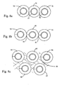
- an array of cyclones may be of various constructions to increase the compactness of the cyclone array or to increase the efficiency of the cyclone array.
- the construction of a cyclone array may employ a common wall between some and preferably all of the cyclones as shown in Figure 8a where three cyclones 74, 75 and 76 within the array 73 are shown with a portion of their walls overlapping in areas 77 and 78 to allow a very compact geometry.
- the construction of a cyclone array 73 can employ a touching wall between some, and preferably all, of the cyclones.
- FIG. 8b An example is shown in Figure 8b where three cyclones 79, 80 and 81 are positioned with their walls touching at positions 82 and 83, which creates a stronger construction with fewer cyclones.
- the construction of a cyclone array 73 may employ spaced apart cyclone walls as shown in Figure 8c where the cyclones 84, 85, 86, 87, and 88 are spaced apart which makes them easier to mold.
- an advantage of spacing the cyclones apart is that the space between the cyclones 84, 85, 86, 87, and 88 may form a region 89 where further particle collection can occur as the air travels (e.g., "spins") to enter the cyclonic inlets of each individual cyclone (e.g., if a manifold is provided which covers all of the cyclone inlets) as opposed to each inlet being connected directly to a fluid flow conduit.
- the common floor 90 between the cyclones 84, 85 and the others from Figure 8 is moved to the bottom of the cyclones 91, the capacity of the annular space 89 for the collection of fine particles will be increased.
- the cyclone arrays described in Figure 8 , 8a, 8b, 8c and 8d are constructed using one or more of the configurations described in Figures 7, 7a, 7b , 7c, and 7d .
- water inlet port 114 may be provided with a closable cap, or other closure member, 116.
- Water inlet port 114 is preferably provided on top surface 108 and is in communication with the fluid flow passage leading to the cyclones (e.g., the dirty air flow passage in a vacuum cleaner extending to the cyclone inlets).
- the inlets preferably are downstream from a header 130 and the water inlet port 114 is provided in the header.
- the water will flow through a passage to the cyclones.
- the user may then use handle 118 to move away, e.g., in a swirling motion.
- the water may be drained, e.g., by pushing button 122 that moves lever outwardly so that bottom door 120 pivots open to permit water and suspended dirt to be removed by passing downwardly out of bottom of stage cyclones 9 (see for example Figure 20 ).
- a plurality of cyclones in parallel may be provided wherein the cyclones have at least two dirt collection chambers, wherein the at least two dirt collection chambers are emptied at the same time.
- the dirt collection chambers may have a common bottom 120 that is openable.
- each cyclone has a dirt collection chamber and all of the dirt collections chambers have a single common door so that, by opening a single door, all of the chambers are emptied at the same time.
- the bottom 120 (not shown) may be pivotally mounted to peripheral wall 92 such that all cyclones are emptied concurrently.
- the surface cleaning apparatus may have two cleaning stages wherein one of the stages, preferably the second, comprises a plurality of cyclones in parallel.
- the other cleaning stage, preferably the first cleaning stage may be any filtration or dirt collection member known in the art.
- the surface cleaning apparatus may have only one cyclonic cleaning stage comprising a plurality of cyclones in parallel wherein the plurality of cyclones are removable as a unit, preferably with the associated dirt collection chamber or chambers.
- second cyclonic cleaning stage 8 which comprises a plurality of cyclones in parallel, may be removed from vacuum cleaner 1 while the first stage cyclone 7 is retained in position in vacuum cleaner 1.
- the second cyclonic cleaning stage may be slidably mounted on flanges 126 that are received in L-shaped members 128 that are provided on the bottom panel of the stage 8, which is preferably a pivoting door 120.
- second cyclonic cleaning stage 8 when removed, e.g., slide in the direction of arrow A, it may be carried to a garbage can, button 122 pressed and door 120 opened so that the second stage cyclones 9 may be emptied.
- Any locking member known in the art may be used to secure second cyclonic cleaning stage 8 in position on the vacuum cleaner and to connect the cyclone array 156 in air flow communication with the respective passages in the surface cleaning apparatus.
- the cyclone array may be sealed in position by means of angled seals, a lifter mechanism or other sealing means known in the art. It will be appreciated that this design may be used if the vacuum cleaner only has one cyclonic cleaning stage.
- first and second cyclonic stages 7, 8 may be removed at the same time from the vacuum cleaner 1. Cyclonic stage 7 may then be emptied, e.g., by opening a bottom pivoting door 50. The cyclonic stages 7, 8 may first, or subsequently, be separated, such as by rotating cyclonic stage 8 relative to cyclonic stage 7 in the direction of arrow B as shown in Figure 19 . The second stage 8 may then be emptied. It will be appreciated that stages 7 and 9 may be emptied in any particular manner known in the art, such as by a bottom pivoting door or the dirt collection chamber being removed from the cyclone chamber.
- the cyclone array is removed as a sealed unit, other than the other than fluid flow passages leading to and from the cyclones.
- air that exits the first stage cyclone 7 travels upwardly from outlet 27, through opening 150 in bottom 120 to one or more openings 148 in the bottom of second cyclonic cleaning stage 8 (See Figure 20 ) that are upstream of header 130 and are connected thereto by a conduit.
- the air travels through the cyclones 9 and exits second cyclones 9 via outlets 13 to header 136 and then to down flow tube 138, which is upstream of conduit 14 and exits second cyclonic stage 8 via opening 152 in bottom 120.
- second stage 8 when second stage 8 is removed from the vacuum cleaner and/or the first stage, second stage 8 is sealed, other then the one or more openings in the bottom of second cyclonic cleaning stage 8 and the bottom 140 of down flow tube 138.
- the array may have a filter that is removable therewith.
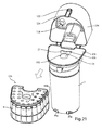
- FIG. 20 Another removal method is exemplified in accordance with the embodiment of Figures 20 and 21 , wherein housing 154 of second cyclonic stage 8 is pivotally mounted to bottom 120 and, when opened, cyclone array 156 may be pulled downwardly out of housing 154 for emptying. Alternately, it will be appreciated that the top of housing 154 may pivot upwardly or otherwise open to permit cyclone array 156 to be pulled upwardly out of housing 154. It will be appreciated that, if the cyclone array 156 is preferably a sealed unit, then a bottom opening panel, with holes aligned with conduits 138 and 146, may be provided.
- the housing 154 may pivot upwardly leaving cyclone array 156 in position on top of the first stage cyclone 7 (or other filtration member or housing member). A consumer may then pick up cyclone array 156, such as by a handle, and remove it for emptying. It will be appreciated that this design may be used if the vacuum cleaner only has one cyclonic cleaning stage.
- a plurality of cyclones are configured such that material that is disentrained by one cyclone is conveyed to another cyclone by introducing the separated material into the fluid flow stream that travels to the other cyclone.
- An example of such an arrangement is shown in Figure 15 .
- a fluid flow duct 1501 branches into ducts 1502 and 1503, which in turn lead to cyclones 1504 and 1505.
- the fluid flowing within duct 1501 continuously or periodically contains one or more types of particles or other materials 1512 which are desired to be removed from the fluid flow stream.
- the cyclone separators 1504 or 1505 may be any cyclone separators or combination of cyclone separators known in the art, or any individual cyclone design or combination of cyclones described within this specification including but not limited to top inlet cyclones, side wall inlet cyclones, bottom inlet inverted cyclones and cyclones with plates.
- the particles 1512 collected in the cyclone separator 1504 are continuously or periodically transferred into the ducts 1501 and/or 1503 by means 1514 so that over time most of the particles are collected in cyclone 1505 other than those which pass to an optional particle separation member 1510 due to the efficiency limitations of cyclones 1505 and 1504.
- the air outlet 1506 from cyclone 1504 passes through duct 1507 to the optional particle separation member 1510, which is adjacent to the suction source 1511.
- One advantage of this configuration is that, when used, e.g., in a vacuum cleaner, the transfer of particles from cyclone 1504 to cyclone 1505 allows the user to empty a single container, which simplifies emptying the vacuum cleaner.
- material collected may be conveyed to container 1513.
- This container 1513 may be reusable or disposable, made of one or more organic or inorganic polymers, rubber, plastic, paper, cardboard, glass or metal, or any combination thereof, and be in the form of a bag, box, bottle, jar, bin or any other closed or semi closed form for easy disposal of the particles or transfer of the particles for other uses or operations. Accordingly, an advantage of this alternate embodiment is that a single automated mechanism may be used to continuously or periodically transfer the collected particles 1512 into a container 1513 as controlled by particle transfer means 1515.
- the container 1513 could optionally be fully or partially closed or sealed by the action of the user or optionally be automatically partially or fully closed or sealed by the mechanism of the system when the user initiates or carries out the release or removal of the container 1513.
- the container 1513 is preferably designed to contain most or all of the particles 1512.
- the container 1513 or a portion of the container 1513 need not be gas or liquid tight but that it may be porous or contain a porous area or member which may optionally facilitate the entry and or exit of fluids, to optionally facilitate the disinfection of the container 1513 and/or its contents by the use of chlorine gas, ozone gas, pure oxygen or other agents, to optionally facilitate the compacting of the container 1513 and/or its contents by allowing gases to escape, and/or facilitates the container 1513 and/or its contents to biodegrade.
- the particle transfer means 1514 may consist of a door mechanism which periodically opens to allow the particles to fall into a region from which the particles 1512 are drawn into ducts 1501 and/or 1503, during which time the suction source 1511 may either be turned off or its influence on cyclone separator 1504 interrupted such as by a valve 1516.
- the particle transfer means 1514 may alternately comprise a rotating member similar to a revolving door disposed vertically, horizontally, or at any angle which continuously or periodically transfers particles 1512 into a region from which the particles are conveyed by gravity or conveyed by means of a mechanism such as a screw or plunger into the duct member 1501 and/or 1503 by means of the duct members 1518 and 1517 respectively during which time the suction source 1511 may either be turned off or its influence on cyclone separator 1504 may optionally be interrupted by an optional member such as a valve 1516.
- the particle transfer means 1515 may be the same as or different from particle transfer means 1514 transferring particles 1512 to container 1513 by means of the duct member 1519 during which time the suction source 1511 may either be turned off or its influence on cyclone separator 1505 may be optionally interrupted by an optional member such as a valve 1520.
- the particle transfer means 1514 and 1515 may alternately each comprise a door that opens and closes periodically or by the action of the user, a vibratory plate, or a vibratory plate in combination with a valve or door.
- the operation of transferring the particles from cyclones 1504 and 1505 may be continuously actuated; automatically actuated on a periodic basis; actuated or halted in response to a particle level within the cyclones or within the container 1513; actuated in response to a sensor; actuated by the interaction of the user with the system such as attempting the removal of the cyclone 1505; the optional container 1513, or by the powering up or powering down of the system, or by a combination of one or more of these methods.
- this invention can be applied to groups or arrays of cyclones wherein 1504 and 1505 represent a plurality of cyclones in parallel rather than a single cyclone.
- the optional particle separation member 1510 may be a cyclone, a plurality of parallel cyclones, two or more cyclones connected in series, two or more cyclonic stages wherein each cyclonic stage comprises a plurality of cyclones in parallel, two or more cyclonic stages wherein each cyclonic stage comprises a plurality of cyclones in parallel and each individual cyclone in an upstream array of cyclones in parallel is in series fluid flow communication with a single cyclone of the downstream array of cyclones in parallel, two or more cyclonic stages wherein each cyclonic stage comprises a plurality of cyclones in parallel and each individual cyclone in an upstream array of cyclones in parallel is in series fluid flow communication with more than one cyclone of the downstream array of cyclones in parallel (e.g.
- each cyclonic stage comprises a plurality of cyclones in parallel and each individual cyclone in an upstream array of cyclones in parallel is in series fluid flow communication with a manifold which feeds at least one cyclone of the downstream stage, a fibrous filter media, a fibrous media with an adhesive or surface treatment applied to aid in fine particle capture or retention, or a liquid bath through which the fluid stream must pass.
- the optional particle separation member 1510 may be physically adjacent to the suction source 1511 or that it may be connected to the suction source 1511 by means of a duct or passage way, which may include one or more bends. It is also understood that the outlet of the cyclones may be through the bottom or side wall of the cyclone, or a combination thereof.
- the fluid flow 1501 may come from a floor nozzle of a vacuum cleaner or other floor cleaning device, from the wand or hose of a vacuum cleaner or other cleaning device, from the air in a room, from a fluid wherein one or more particles sizes or types is to be separated, from another source similar to those described above with reference to optional particle separation member 1510 or from a liquid bath through which the fluid stream must pass.
- FIG. 15a shows a fluid flow duct 1501, which leads to cyclone separator 1505.
- the fluid flowing within duct 1501 continuously or periodically contains one or more types of particles or other materials 1512 which it is desired be removed from said fluid flow stream.
- the cyclone separator 1504 may be designed to capture finer particles more efficiently as it is in series with and downstream of cyclone separator 1505.
- the particles 1512 collected in the cyclone separator 1504 are continuously or periodically transferred by means 1514 into the duct 1501 so that over time more of the particles collect in cyclone 1505.
- the particle transfer means 1514 operates exactly as described with respect to Figure 15 except that it only feeds into fluid flow duct 1501 by means of duct member 1518.
- the particle transfer means 1515 operates exactly as described with respect to Figure 15 except that in operation valve 1516 would be used to optionally disrupt the influence of suction source 1516 on cyclone 1505 as the cyclones 1504, 1505 are in series.
- the air outlet 1506 from cyclone 1504 passes through duct 1507 to the optional particle separation member 1510, which is adjacent to the suction source 1511. It is also understood that an optional particle separation member 1510a, which is adjacent to the outlet of the suction source 1511 can also be provided. It is understood that the members 1510 and 1510a may optionally be removed together for cleaning and may be placed mechanically adjacent to each other. It is understood that the optional particle separation member 1510 or 1510a may be the same as described with respect to Figure 15 .
- the optional particle separation member 1510 or 1510a may be physically adjacent to the suction source 1511 or that it may be connected to said suction by means of a duct or passage way which may include one or more bends. It is also understood that the outlet of the cyclones way be through the bottom or sidewall of the cyclone, or a combination thereof.
- fluid flow 1501 may come from any source as described with respect to Figure 15 .
- the cyclone separators 1504 and 1505 may each represent a single or a plurality of parallel cyclones, and that this invention may be applied to more than two sequential cyclones so that the particles 1512 are collected in a number of cyclones or cyclone stages which is less than the total number of cyclones or cyclone stages.
- 1510 or 1510a may themselves be a plurality of cyclones mounted into the wall or the portion of the wall of a larger cyclone thereby creating a structure which minimizes energy losses in connecting ducts.
- the structures described in Figures 15 and 15A can be configured to remove nano-sized particles and live virus particles.
- a surface cleaning apparatus has a plurality of cyclones in parallel 9 having at least one dirt collection chamber 52 wherein at least a portion of the dirt collection chamber below the maximum fill position (which may be a maximum fill line marked on the housing) is transparent.
- second stage cyclones each have a dirt collection chamber 52 having an outer wall 100 that is transparent.
- cyclone chamber 102 has an outer wall 104 that is transparent.
- Second stage cyclones 9 are provided within a casing or housing having a side wall 106 and a top wall 108 which are transparent. Provided that a portion of side wall 106 that is outward of the maximum fill line of dirt collection chamber 52 is transparent, then a user may view the maximum fill line or position and determine when to empty the second stage dirt collection chambers 52.
- each of the second stage cyclones and the second stage cyclone housings may be made from transparent plastic (which may be shaded or tinted but still permit a user to see therethrough) and that part may be masked by a label or coating so as to render part thereof opaque.
- the user can view when the dirt collection chamber(s) 52 are full, the user will have a visual signal to clean or empty the second stage cyclones.
- This design is particularly preferred when the plurality of cyclones 9 has an associated plurality of dirt collection chambers 52, and preferably each cyclone 9 has an associated dirt collection chamber 52, and, particularly, when the cyclones 9 are emptied separately from another cleaning stage.
- a filter 112 (e.g., foam, HEPA, etc.) may be provided in a housing 110 wherein at least a portion of the housing that is visible, or may be made visible, is transparent. Preferably, all of housing 110 is transparent plastic. This permits a user to notice when filter 112 is dirty and requires cleaning or replacement.
- housing 110 is a pre-motor filter. Accordingly, for example, housing 112 may be provided in pre-motor area 16. Thus when cyclonic cleaning unit 6 is removed, a user can view housing 110, e.g., the top thereof.
- filter 112 which is not provided in the cyclone chamber, may be visible through a transparent side wall of the vacuum cleaner or may housing 110 may be visible when a door that is provided in the vacuum cleaner is opened.
- An advantage of using a housing is that the consumer need not touch filter 112 when removing filter 112 from the vacuum cleaner.
- one or more filters may be removable with the cyclone array 156 and that these may be provided in a housing, a portion or all of which is transparent.
- any or all of the embodiments may be used individually or in combination or sub-combinations. In addition to their use in surface cleaning appliances and other domestic appliances and breathing masks, they may also be used, singly or in combination, in other applications.
- the cyclonic embodiments described herein may be used in conjunction with a fan or other air moving means to create a sweeper, a sweeper with suction, a vacuum cleaner, a canister vacuum cleaner, an upright vacuum cleaner, a wet/dry vacuum cleaner, a stick vacuum cleaner, a carpet shampooer, a carpet extractor, a hand vacuum, a back pack vacuum, a vehicle mounted vacuum, or any other type of vacuum cleaner or dust extractor or to pick up unwanted particles and to subsequently remove unwanted particles from air.
- a fan or other air moving means to create a sweeper, a sweeper with suction, a vacuum cleaner, a canister vacuum cleaner, an upright vacuum cleaner, a wet/dry vacuum cleaner, a stick vacuum cleaner, a carpet shampooer, a carpet extractor, a hand vacuum, a back pack vacuum, a vehicle mounted vacuum, or any other type of vacuum cleaner or dust extractor or to pick up unwanted particles and to subsequently remove unwanted particles from air.
- cyclonic embodiments described herein may be applied to the inlet for cooling air to, and/or the outlet of air from, computers, electronic equipment, or mechanical equipment to protect a computer or equipment from particles, which may damage them or impair their function.
- cyclonic embodiments described herein may be used in conjunction with a fan or other air moving means to create an air cleaner, air purifier, airborne particle capture system, fan with a particle capture system, automotive cabin air filter, heating, cooling or ventilation system to capture unwanted particles from an air stream.
- cyclonic embodiments described herein may be used in conjunction with a fan or other air moving means to create a filter mask to capture unwanted particles from an air stream.
- a filter mask constructed with the cyclones descried in this specification or with any cyclones known in the art may be designed to filter the air that a person breathes in, breathes out, or both, so as to be able to create a portable means of isolating a person from their surrounding environment.
- a small fan may optionally be used to reduce the pressure that the person must exert with their lungs to breathe in and/or out through the cyclonic means.
- the cyclonic embodiments described herein may be used in conjunction with a fluid moving device to create a means of removing unwanted particles from fluid.
- the cyclonic embodiments described in this specification may be placed in the duct leading to the fluid moving member, either directly adjacent or some distance away, to protect the fluid moving member from the particles and to remove them.
- the cyclonic embodiments described herein may alternately or also be placed in the duct leading from a fluid moving member, either directly adjacent or some distance away, to protect equipment downstream from the fluid moving member from the particles which the fluid moving member may introduce to the fluid stream.
- the positioning of the cyclonic embodiments described herein may be mechanically arranged so that they can both be removed for cleaning or servicing together.
- the cyclonic inventions described herein may be used to reduce the particle emissions from any type of burner used to heat homes, heat water, and to remove emissions from the exhaust gasses from industrial processes, the exhaust gasses from internal combustion engines, the exhaust gasses from external combustion engines and the exhaust gasses from turbine engines.
- the cyclonic embodiments described herein may be placed in the duct leading to or from the emission source, either directly adjacent or some distance away, to protect the particle emission causing device from particles in the air stream which they require to operate.
- the cyclonic embodiments described herein may alternately or also be placed in the duct leading from the particle emissions source, either directly adjacent or some distance away, to protect equipment downstream from the emissions source and the environment from the particles which the emissions source may introduce into its exhaust stream.
- the advantage of the multi stage cyclonic separation means described herein is that a vacuum cleaner, filter mask or other apparatus mentioned herein may be produced which can optionally reach HEPA or ULPA separation levels without the use of a filter.
- the cyclonic separation means employed in this manner may be cleaned or disposed of, or a combination thereof.
- the fan means used in any aspect may be a two to ten stage fan system operating from one or more motors in series or in parallel and the fan may be a propeller, an impeller, a Prandtl layer turbine also known as a Tesla turbine, or a combination thereof.
- the vacuum cleaner may be powered by means of a Stirling engine, a steam engine, or an internal combustion engine wherein said Stirling engine, steam engine, or internal combustion engine may optionally be operated from hydrogen gas produced by electricity from the wall or from a battery or produced by a chemical reaction or which may optionally be withdrawn from a storage vessel.
- the option to manually or automatically switch the hydrogen source powering the vacuum from one source to another may be provided.
- a hydrogen powered appliance including surface cleaning apparatus and other appliances for indoor use, may operate using any design known in the respective arts.
- Hydrogen produced by electricity when an appliance, e.g. a surface cleaning apparatus, preferably a vacuum cleaner, is plugged into an electric outlet may be used to power the surface cleaning apparatus. All or a portion of the hydrogen may be stored for cordless operation. It will be appreciated that some hydrogen may be used as it is generated to operate the device. Such a hydrogen powered surface cleaning apparatus may be used alone or in combination with any other embodiment disclosed herein.
- the hydrogen produced by electricity when the vacuum is plugged in but not being used is a preferred method of operating.
- the storage means contemplated is any means known in the art including but not limited to pressurized storage, storage in a metal hydride or other adsorptive storage means.
- the hydrogen stored may be produced by fuel reforming, chemical reactions or by electrolysis. Alternately, or in addition, a central hydrogen generator which charges a small portable "vessel" which is plugged into the air cleaning device may be provided.
- an adhesive material such as agar or pectin or a rubber based adhesive may be applied to the all or a portion of interior surfaces of cyclone separator 20 to assist in the capture and retention of fine particles.
- the adhesive can be applied to the interior and exterior of the down flow tubes 27b and 27c and/or plate 32 which may be removed for cleaning when the bottom of the cyclones is removed or this section may be disposed of and replaced with a clean piece with fresh adhesive.
- the mesh used to construct the screen 28 may incorporate an adhesive or micro-filaments, which aid in the entrapment of fibers, hairs or particles. Accordingly, if the screen 28 comprises an adhesive material, it will be appreciated that the screen 28 may be disposable.
- the plate may be made from or coated with a fibrous material, such as micro filaments, to assist in retaining dirt in the cyclone casing. It will be appreciated that, in accordance with such embodiments, the plate may be disposable.
- a water mist created preferably, by means of electrostatically and/or mechanically atomization can be placed upstream of a cyclonic embodiment described herein or any cyclonic separation means known in the art to create a humidification means wherein the particles which do not become collected are cyclonically removed from the fluid flow stream.
- a cyclonic embodiment described herein or any cyclonic separation means known in the art may be placed upstream of the mist source to prevent airborne particles from contaminating or otherwise interfering with the operation of the mist source.
- the water which does not evaporate, may be recirculated though a filter and/or ozone disinfection and oxidation system and/or ultra violet light disinfection system before it is reused in the atomization process. If ozonated water is used to create the mist, air disinfection can be achieved before a down stream cyclone separator is employed to remove the remaining ozonated water droplets from the air stream.
- ozone gas can be introduced into an air stream to oxidize pollutants and to disinfect airborne particles upstream and that the down stream cyclone separator can remove oxidized particles and that if optionally, an electrostatic and/or mechanical atomization mist source is employed, the ozone gas can be captured in the water droplets and the water droplets can be removed by means of a down stream cyclone separator.
- the improvements may be used in a single application, or individually or in sub-combinations.
- the improvements in the design of cyclones and arrays of cyclones may be used in a single application, or individually or in sub-combinations.
- one or more of the improvements may be used in a single vacuum cleaner.
- the improvements which are selected may be determined based on the degree of particulate removal which is required, whether a pre and/or post motor filter is utilized, the amount of back pressure which may be produced by the air flow path through the vacuum cleaner, the power of the suction motor and the like.
Applications Claiming Priority (2)
| Application Number | Priority Date | Filing Date | Title |
|---|---|---|---|
| US78082406P | 2006-03-10 | 2006-03-10 | |
| PCT/CA2007/000377 WO2007104138A1 (en) | 2006-03-10 | 2007-03-09 | Vacuum cleaner with a removable cyclone array |
Publications (3)
| Publication Number | Publication Date |
|---|---|
| EP1996059A1 EP1996059A1 (en) | 2008-12-03 |
| EP1996059A4 EP1996059A4 (en) | 2009-07-08 |
| EP1996059B1 true EP1996059B1 (en) | 2012-08-15 |
Family
ID=38508990
Family Applications (3)
| Application Number | Title | Priority Date | Filing Date |
|---|---|---|---|
| EP07710711A Not-in-force EP1996059B1 (en) | 2006-03-10 | 2007-03-09 | Vacuum cleaner with a removable cyclone array |
| EP07719394A Active EP1996336B1 (en) | 2006-03-10 | 2007-03-09 | Vacuum cleaner with a divider |
| EP07710712A Not-in-force EP1996060B1 (en) | 2006-03-10 | 2007-03-09 | Vacuum cleaner with a removable cyclone array |
Family Applications After (2)
| Application Number | Title | Priority Date | Filing Date |
|---|---|---|---|
| EP07719394A Active EP1996336B1 (en) | 2006-03-10 | 2007-03-09 | Vacuum cleaner with a divider |
| EP07710712A Not-in-force EP1996060B1 (en) | 2006-03-10 | 2007-03-09 | Vacuum cleaner with a removable cyclone array |
Country Status (11)
| Country | Link |
|---|---|
| US (11) | US7811345B2 (ja) |
| EP (3) | EP1996059B1 (ja) |
| JP (3) | JP2009529384A (ja) |
| KR (3) | KR20080108285A (ja) |
| CN (3) | CN101466295B (ja) |
| AT (2) | ATE523128T1 (ja) |
| AU (3) | AU2007224961B2 (ja) |
| CA (10) | CA2643127C (ja) |
| DE (1) | DE102007011457A1 (ja) |
| GB (3) | GB2449606A (ja) |
| WO (4) | WO2007104141A1 (ja) |
Families Citing this family (294)
| Publication number | Priority date | Publication date | Assignee | Title |
|---|---|---|---|---|
| US8978197B2 (en) * | 2009-03-13 | 2015-03-17 | Lg Electronics Inc. | Vacuum cleaner |
| US8404034B2 (en) * | 2005-12-10 | 2013-03-26 | Lg Electronics Inc. | Vacuum cleaner and method of controlling the same |
| US7987551B2 (en) * | 2005-12-10 | 2011-08-02 | Lg Electronics Inc. | Vacuum cleaner |
| US7749295B2 (en) * | 2005-12-10 | 2010-07-06 | Lg Electronics Inc. | Vacuum cleaner with removable dust collector, and methods of operating the same |
| US7770253B2 (en) * | 2005-12-10 | 2010-08-10 | Lg Electronics Inc. | Vacuum cleaner with removable dust collector, and methods of operating the same |
| US7785396B2 (en) | 2005-12-10 | 2010-08-31 | Lg Electronics Inc. | Vacuum cleaner with removable dust collector, and methods of operating the same |
| US8544143B2 (en) * | 2005-12-10 | 2013-10-01 | Lg Electronics Inc. | Vacuum cleaner with removable dust collector, and methods of operating the same |
| US8281455B2 (en) * | 2005-12-10 | 2012-10-09 | Lg Electronics Inc. | Vacuum cleaner |
| US7882592B2 (en) * | 2005-12-10 | 2011-02-08 | Lg Electronics Inc. | Vacuum cleaner |
| US8012250B2 (en) * | 2005-12-10 | 2011-09-06 | Lg Electronics Inc. | Vacuum cleaner |
| US7811345B2 (en) | 2006-03-10 | 2010-10-12 | G.B.D. Corp. | Vacuum cleaner with a removable cyclone array |
| US7466256B2 (en) * | 2006-03-31 | 2008-12-16 | Siemens Medical Solutions Usa, Inc. | Universal ultrasound sigma-delta receiver path |
| US7604675B2 (en) * | 2006-06-16 | 2009-10-20 | Royal Appliance Mfg. Co. | Separately opening dust containers |
| KR20080000188A (ko) * | 2006-06-27 | 2008-01-02 | 엘지전자 주식회사 | 진공 청소기의 집진 유닛 |
| NO326078B1 (no) * | 2006-07-07 | 2008-09-15 | Shell Int Research | Fluidseparasjonskar |
| US10765277B2 (en) | 2006-12-12 | 2020-09-08 | Omachron Intellectual Property Inc. | Configuration of a surface cleaning apparatus |
| CN101626715B (zh) | 2006-12-12 | 2012-07-25 | Gbd公司 | 可转换的表面清洁设备 |
| CA2599303A1 (en) | 2007-08-29 | 2009-02-28 | Gbd Corp. | Surface cleaning apparatus |
| US8950039B2 (en) | 2009-03-11 | 2015-02-10 | G.B.D. Corp. | Configuration of a surface cleaning apparatus |
| US9301666B2 (en) | 2006-12-12 | 2016-04-05 | Omachron Intellectual Property Inc. | Surface cleaning apparatus |
| US8869344B2 (en) | 2006-12-12 | 2014-10-28 | G.B.D. Corp. | Surface cleaning apparatus with off-centre dirt bin inlet |
| US9888817B2 (en) | 2014-12-17 | 2018-02-13 | Omachron Intellectual Property Inc. | Surface cleaning apparatus |
| US9192269B2 (en) | 2006-12-15 | 2015-11-24 | Omachron Intellectual Property Inc. | Surface cleaning apparatus |
| US20210401246A1 (en) | 2016-04-11 | 2021-12-30 | Omachron Intellectual Property Inc. | Surface cleaning apparatus |
| US10165912B2 (en) | 2006-12-15 | 2019-01-01 | Omachron Intellectual Property Inc. | Surface cleaning apparatus |
| US11857142B2 (en) | 2006-12-15 | 2024-01-02 | Omachron Intellectual Property Inc. | Surface cleaning apparatus having an energy storage member and a charger for an energy storage member |
| EP1949842B1 (en) * | 2007-01-24 | 2015-03-04 | LG Electronics Inc. | Vacuum cleaner |
| SE531272C2 (sv) * | 2007-03-02 | 2009-02-10 | Electrolux Ab | Dammsugare |
| SE531273C2 (sv) * | 2007-03-02 | 2009-02-10 | Electrolux Ab | Dammsugare |
| US20080201898A1 (en) * | 2007-02-23 | 2008-08-28 | Charbonneau Gary P | Self-cleaning filter arrangement with activation signal for floor care apparatus |
| US20080264015A1 (en) * | 2007-04-30 | 2008-10-30 | Samsung Gwangju Electronics Co., Ltd | Dust compressing apparatus of vacuum cleaner |
| CN101730495B (zh) * | 2007-05-15 | 2013-10-23 | 皇家器具有限公司 | 旋流式通用真空装置 |
| EP2164641A1 (en) * | 2007-06-01 | 2010-03-24 | Shell Internationale Research Maatschappij B.V. | Gas-solids separator |
| GB2450737B (en) * | 2007-07-05 | 2011-10-12 | Dyson Technology Ltd | Cyclonic separating apparatus |
| US11751733B2 (en) | 2007-08-29 | 2023-09-12 | Omachron Intellectual Property Inc. | Portable surface cleaning apparatus |
| GB2453949B (en) * | 2007-10-23 | 2012-03-28 | Hoover Ltd | Cyclonic separation apparatus |
| EP2231303A4 (en) * | 2007-12-06 | 2014-06-11 | Techtronic Floor Care Tech Ltd | TWO-STAGE CYCLONE DUST COLLECTORS |
| US8209815B2 (en) * | 2007-12-06 | 2012-07-03 | Techtronic Floor Care Technology Limited | Dual stage cyclonic dust collector |
| WO2009076774A1 (en) | 2007-12-19 | 2009-06-25 | Gbd Corp. | Configuration of a cyclone assembly and surface cleaning apparatus having same |
| DE102008004393B3 (de) * | 2008-01-14 | 2009-07-16 | Miele & Cie. Kg | Vorrichtung zum Abscheiden von Staub aus staubbeladener Luft, insbesondere zur Verwendung in einem Staubsauger |
| US7981181B2 (en) * | 2008-01-16 | 2011-07-19 | Samsung Gwangju Electronics Co., Ltd. | Cyclone dust-separating apparatus and cleaner having the same |
| US20090193613A1 (en) * | 2008-02-04 | 2009-08-06 | Ruben Brian K | Dirt cup with secondary cyclonic cleaning chambers |
| NL2001293C2 (nl) * | 2008-02-18 | 2009-08-19 | Jadyba B V | Gasreiniger voor het ten minste gedeeltelijk uit een vervuilde gasstroom separeren van meegevoerde componenten. |
| AU2009202183B2 (en) | 2008-06-05 | 2013-11-14 | Bissell Inc. | Cyclonic vacuum cleaner with improved filter cartridge |
| US7984567B2 (en) * | 2008-10-07 | 2011-07-26 | Christ Bill Bertakis | Apparatus for cleaning simulated hair articles |
| US20100089014A1 (en) * | 2008-10-15 | 2010-04-15 | Changzhou Shinri Household Appliance Manufacturing Co., Ltd. | Cyclonic separation device for vacuum cleaner |
| US9572465B2 (en) | 2008-12-08 | 2017-02-21 | Emerson Electric Co. | Slide out drum with filter for a wet/dry vacuum appliance |
| US8973196B2 (en) * | 2008-12-08 | 2015-03-10 | Emerson Electric Co. | Slide-out drum with filter for a wet/dry vacuum appliance |
| DE102008055047A1 (de) * | 2008-12-19 | 2010-06-24 | BSH Bosch und Siemens Hausgeräte GmbH | Staubsauger mit einem Fliehkraftabscheider |
| US8062398B2 (en) * | 2008-12-19 | 2011-11-22 | Bissell Homecare, Inc. | Vacuum cleaner and cyclone module therefor |
| US7867310B2 (en) * | 2009-01-29 | 2011-01-11 | General Electric Company | Method and apparatus for separating air and oil |
| US7992252B2 (en) * | 2009-02-12 | 2011-08-09 | Lg Electronics Inc. | Vacuum cleaner |
| US8151409B2 (en) * | 2009-02-26 | 2012-04-10 | Lg Electronics Inc. | Vacuum cleaner |
| CA2658046A1 (en) * | 2009-03-11 | 2010-09-11 | G.B.D. Corp. | Surface cleaning apparatus |
| US9591952B2 (en) * | 2009-03-11 | 2017-03-14 | Omachron Intellectual Property Inc. | Hand vacuum cleaner with removable dirt chamber |
| US9427122B2 (en) | 2009-03-13 | 2016-08-30 | Omachron Intellectual Property Inc. | Surface cleaning apparatus |
| US9226633B2 (en) | 2009-03-13 | 2016-01-05 | Omachron Intellectual Property Inc. | Surface cleaning apparatus |
| US8713752B2 (en) | 2009-03-13 | 2014-05-06 | Lg Electronics Inc. | Vacuum cleaner |
| CA2674376A1 (en) | 2009-03-13 | 2010-09-13 | G.B.D. Corp. | Surface cleaning apparatus with different cleaning configurations |
| US10667663B2 (en) | 2018-03-27 | 2020-06-02 | Omachron Intellectual Property Inc. | Surface cleaning apparatus with an arrester plate having a variable gap |
| CA2658159A1 (en) * | 2009-03-13 | 2010-09-13 | G.B.D. Corp. | Dirt collection chamber for a cyclonic surface cleaning apparatus |
| US11229340B2 (en) * | 2010-03-12 | 2022-01-25 | Omachron Intellectual Property Inc. | Surface cleaning apparatus with an arrester plate having a variable gap |
| US10791895B2 (en) | 2018-03-27 | 2020-10-06 | Omachron Intellectual Property Inc. | Surface cleaning apparatus with dirt arrester having an axial step |
| US9480373B2 (en) | 2009-03-13 | 2016-11-01 | Omachron Intellectual Property Inc. | Surface cleaning apparatus |
| US10722086B2 (en) | 2017-07-06 | 2020-07-28 | Omachron Intellectual Property Inc. | Handheld surface cleaning apparatus |
| CA2674761C (en) | 2009-03-13 | 2016-10-04 | G.B.D. Corp. | Surface cleaning apparatus with different cleaning configurations |
| US9198551B2 (en) | 2013-02-28 | 2015-12-01 | Omachron Intellectual Property Inc. | Surface cleaning apparatus |
| US11612288B2 (en) | 2009-03-13 | 2023-03-28 | Omachron Intellectual Property Inc. | Surface cleaning apparatus |
| US9211044B2 (en) | 2011-03-04 | 2015-12-15 | Omachron Intellectual Property Inc. | Compact surface cleaning apparatus |
| US9591953B2 (en) | 2009-03-13 | 2017-03-14 | Omachron Intellectual Property Inc. | Surface cleaning apparatus |
| US9138114B2 (en) * | 2009-03-13 | 2015-09-22 | Omachron Intellectual Property Inc. | Surface cleaning apparatus |
| US11690489B2 (en) | 2009-03-13 | 2023-07-04 | Omachron Intellectual Property Inc. | Surface cleaning apparatus with an external dirt chamber |
| CA2967272C (en) | 2009-03-13 | 2018-01-02 | Omachron Intellectual Property Inc. | Hand vacuum cleaner |
| US9433332B2 (en) | 2013-02-27 | 2016-09-06 | Omachron Intellectual Property Inc. | Surface cleaning apparatus |
| US9265395B2 (en) | 2010-03-12 | 2016-02-23 | Omachron Intellectual Property Inc. | Surface cleaning apparatus |
| US9392916B2 (en) | 2009-03-13 | 2016-07-19 | Omachron Intellectual Property Inc. | Surface cleaning apparatus |
| US8107983B2 (en) * | 2009-03-16 | 2012-01-31 | Telefonaktiebolaget L M Ericsson | Systems and method for coordinated multipoint downlink transmissions |
| EP2264560A1 (en) * | 2009-06-02 | 2010-12-22 | Koninklijke Philips Electronics N.V. | Appliance with luminous housing control depending on environment color |
| US8774970B2 (en) * | 2009-06-11 | 2014-07-08 | S.C. Johnson & Son, Inc. | Trainable multi-mode floor cleaning device |
| US20110023261A1 (en) * | 2009-07-29 | 2011-02-03 | Proffitt Ii Donald E | Filterless and bagless vacuum cleaner incorporating a sling shot separator |
| AU2010214785B2 (en) * | 2009-09-10 | 2014-06-12 | Bissell Inc. | Extraction cleaner and centrifugal air/water separator therefor |
| US8393050B2 (en) * | 2009-10-28 | 2013-03-12 | Robert M. Witter | Portable cyclonic dust collector/vacuum cleaner |
| JP5413130B2 (ja) | 2009-11-02 | 2014-02-12 | コニカミノルタ株式会社 | 着脱可能なトナー捕集ユニットを有する画像形成装置 |
| WO2011058365A1 (en) * | 2009-11-16 | 2011-05-19 | Dyson Technology Limited | A surface treating appliance |
| WO2011106840A1 (en) * | 2010-03-05 | 2011-09-09 | Xtralis Technologies Ltd | Particle precipitator |
| US8640304B2 (en) | 2010-03-12 | 2014-02-04 | G.B.D. Corp. | Cyclone construction for a surface cleaning apparatus |
| US8375508B2 (en) * | 2010-03-12 | 2013-02-19 | G.B.D. Corp. | Torque balancer for a surface cleaning head |
| US8296900B2 (en) * | 2010-03-12 | 2012-10-30 | G.B.D. Corp. | Seal construction for a surface cleaning apparatus |
| US8875340B2 (en) | 2010-03-12 | 2014-11-04 | G.B.D. Corp. | Surface cleaning apparatus with enhanced operability |
| US20110219579A1 (en) * | 2010-03-12 | 2011-09-15 | G.B.D. Corp. | Suction motor housing for an upright surface cleaning apparatus |
| JP5505031B2 (ja) * | 2010-03-30 | 2014-05-28 | コニカミノルタ株式会社 | 画像形成システム、及びサイクロン捕集システム |
| US20120108147A1 (en) * | 2010-11-02 | 2012-05-03 | Ronald Benson | Removable airwash cartridge or cassette for grit drying system |
| US8973214B2 (en) | 2011-03-03 | 2015-03-10 | G.B.D. Corp. | Cyclone chamber and dirt collection assembly for a surface cleaning apparatus |
| US8769767B2 (en) | 2011-03-03 | 2014-07-08 | G.B.D. Corp. | Removable cyclone chamber and dirt collection assembly for a surface cleaning apparatus |
| US9101252B2 (en) | 2011-03-03 | 2015-08-11 | G.B.D. Corp. | Configuration of a surface cleaning apparatus |
| US8813306B2 (en) | 2011-03-03 | 2014-08-26 | G.B.D. Corp. | Openable side compartments for a surface cleaning apparatus |
| US8869345B2 (en) | 2011-03-03 | 2014-10-28 | G.B.D. Corp. | Canister vacuum cleaner |
| US8763202B2 (en) | 2011-03-03 | 2014-07-01 | G.B.D. Corp. | Cyclone chamber and dirt collection assembly for a surface cleaning apparatus |
| US8973212B2 (en) | 2011-03-03 | 2015-03-10 | G.B.D. Corp. | Filter housing construction for a surface cleaning apparatus |
| US8739359B2 (en) | 2011-03-03 | 2014-06-03 | G.B.D. Corp. | Configuration of a surface cleaning apparatus |
| US8978198B2 (en) | 2011-03-03 | 2015-03-17 | G.B.D. Corp. | Filter housing for a surface cleaning apparatus |
| US8646149B2 (en) | 2011-03-03 | 2014-02-11 | G.B.D. Corp. | Filter housing construction for a surface cleaning apparatus |
| US8739357B2 (en) | 2011-03-03 | 2014-06-03 | G.B.D. Corp | Filter construction for a surface cleaning apparatus |
| US8683644B2 (en) | 2011-03-04 | 2014-04-01 | G.B.D. | Automatic cord release |
| US8601641B2 (en) | 2011-03-04 | 2013-12-10 | G.B.D. Corp. | Removable cyclone chamber and dirt collection assembly for a surface cleaning apparatus |
| US8689395B2 (en) | 2011-03-04 | 2014-04-08 | G.B.D. Corp. | Portable surface cleaning apparatus |
| WO2012119221A1 (en) * | 2011-03-04 | 2012-09-13 | Gbd Corp. | Surface cleaning apparatus |
| US9962052B2 (en) | 2011-03-04 | 2018-05-08 | Omachron Intellectual Property Inc. | Surface cleaning apparatus |
| US9232881B2 (en) | 2011-03-04 | 2016-01-12 | Omachron Intellectual Property Inc. | Surface cleaning apparatus with removable handle assembly |
| US8646146B2 (en) | 2011-03-04 | 2014-02-11 | G.B.D. Corp. | Suction hose wrap for a surface cleaning apparatus |
| GB2489408B (en) * | 2011-03-23 | 2015-08-05 | Techtronic Floor Care Tech Ltd | Suction cleaner |
| GB201106455D0 (en) | 2011-04-15 | 2011-06-01 | Dyson Technology Ltd | Cyclonic separator |
| GB201106454D0 (en) * | 2011-04-15 | 2011-06-01 | Dyson Technology Ltd | Cyclonic separator |
| AU2012241550B2 (en) * | 2011-04-15 | 2015-08-20 | Dyson Technology Limited | Cyclonic separator comprising an outlet duct extending between two adjacent cyclone bodies |
| GB2492743B (en) | 2011-05-11 | 2015-01-14 | Dyson Technology Ltd | A surface treating appliance |
| GB2490697B (en) | 2011-05-11 | 2015-01-14 | Dyson Technology Ltd | A surface treating appliance |
| GB2490692B (en) | 2011-05-11 | 2014-12-17 | Dyson Technology Ltd | A cyclonic surface treating appliance with multiple cyclones |
| GB2490695B (en) | 2011-05-11 | 2015-01-14 | Dyson Technology Ltd | A surface treating appliance |
| GB2490693B (en) * | 2011-05-11 | 2014-12-17 | Dyson Technology Ltd | A cyclonic surface treating appliance with multiple cyclones |
| GB2490696B (en) | 2011-05-11 | 2014-12-17 | Dyson Technology Ltd | A cyclonic surface treating appliance with multiple cyclones |
| GB2492744B (en) | 2011-05-11 | 2014-12-24 | Dyson Technology Ltd | A multi-cyclonic surface treating appliance |
| GB2490694B (en) | 2011-05-11 | 2015-01-14 | Dyson Technology Ltd | A surface treating appliance |
| USD673155S1 (en) * | 2011-06-16 | 2012-12-25 | Pfu Limited | Scanner |
| DE102011081044A1 (de) * | 2011-08-16 | 2013-02-21 | BSH Bosch und Siemens Hausgeräte GmbH | Staubabscheideeinrichtung, insbesondere für Staubsauger |
| US8728186B2 (en) * | 2011-09-02 | 2014-05-20 | Samsung Electronics Co., Ltd. | Vacuum cleaner and dust separating apparatus thereof |
| DE102011083449B4 (de) * | 2011-09-26 | 2014-11-06 | BSH Bosch und Siemens Hausgeräte GmbH | Auffangbehälter für einen Zyklon-Staubsauger |
| EP2612583B1 (de) | 2012-01-04 | 2015-07-08 | Miele & Cie. KG | Beutelloser Staubsauger mit einem Staubbehälter |
| DE102012100041A1 (de) * | 2012-01-04 | 2013-07-04 | Miele & Cie. Kg | Staubsauger mit einem Staubbehälter |
| US9149165B2 (en) | 2012-03-08 | 2015-10-06 | Bissell Homecare, Inc. | Vacuum cleaner and vacuum cleaner system |
| DE102012012727A1 (de) * | 2012-06-26 | 2014-01-02 | Hydac Process Technology Gmbh | Vorrichtung zur Konditionierung von Gasen |
| DE102012211249A1 (de) | 2012-06-29 | 2014-01-02 | BSH Bosch und Siemens Hausgeräte GmbH | Staubabscheideeinheit für einen Staubsauger und Staubsauger |
| DE102012211253A1 (de) | 2012-06-29 | 2014-01-02 | BSH Bosch und Siemens Hausgeräte GmbH | Staubsauger mit Staubfilter |
| US8997310B2 (en) | 2012-10-12 | 2015-04-07 | Electrolux Home Care Products, Inc. | Vacuum cleaner cyclone with helical cyclone expansion region |
| US10352325B2 (en) | 2012-10-29 | 2019-07-16 | Exhale Fans LLC | Laminar flow radial ceiling fan |
| US9366206B2 (en) * | 2012-12-17 | 2016-06-14 | Ford Global Technologies, Llc | Fuel-air separator and pulse dampener |
| US20140196248A1 (en) * | 2013-01-16 | 2014-07-17 | Techtronic Floor Care Technology Limited | Debris collection device for bagless vacuum cleaners |
| US20140196244A1 (en) * | 2013-01-16 | 2014-07-17 | Techtronic Floor Care Technology Limited | Cleaning apparatus with backlit debris receptacle and method of illuminating dirt collection |
| US8679211B1 (en) | 2013-02-11 | 2014-03-25 | Techtronic Floor Care Technology Limited | Cyclonic separator assembly for a vacuum cleaner |
| US9027198B2 (en) | 2013-02-27 | 2015-05-12 | G.B.D. Corp. | Surface cleaning apparatus |
| US9591958B2 (en) | 2013-02-27 | 2017-03-14 | Omachron Intellectual Property Inc. | Surface cleaning apparatus |
| US9320401B2 (en) | 2013-02-27 | 2016-04-26 | Omachron Intellectual Property Inc. | Surface cleaning apparatus |
| US9451855B2 (en) | 2013-02-28 | 2016-09-27 | Omachron Intellectual Property Inc. | Surface cleaning apparatus |
| US9227201B2 (en) | 2013-02-28 | 2016-01-05 | Omachron Intellectual Property Inc. | Cyclone such as for use in a surface cleaning apparatus |
| US9204773B2 (en) | 2013-03-01 | 2015-12-08 | Omachron Intellectual Property Inc. | Surface cleaning apparatus |
| US9326652B2 (en) | 2013-02-28 | 2016-05-03 | Omachron Intellectual Property Inc. | Surface cleaning apparatus |
| US9227151B2 (en) | 2013-02-28 | 2016-01-05 | Omachron Intellectual Property Inc. | Cyclone such as for use in a surface cleaning apparatus |
| US9820621B2 (en) | 2013-02-28 | 2017-11-21 | Omachron Intellectual Property Inc. | Surface cleaning apparatus |
| US9215960B2 (en) | 2013-02-28 | 2015-12-22 | Omachron Intellectual Property Inc. | Surface cleaning apparatus |
| US9364127B2 (en) | 2013-02-28 | 2016-06-14 | Omachron Intellectual Property Inc. | Surface cleaning apparatus |
| US9295995B2 (en) | 2013-02-28 | 2016-03-29 | Omachron Intellectual Property Inc. | Cyclone such as for use in a surface cleaning apparatus |
| US9314138B2 (en) | 2013-02-28 | 2016-04-19 | Omachron Intellectual Property Inc. | Surface cleaning apparatus |
| US9427126B2 (en) | 2013-03-01 | 2016-08-30 | Omachron Intellectual Property Inc. | Surface cleaning apparatus |
| US9456721B2 (en) | 2013-02-28 | 2016-10-04 | Omachron Intellectual Property Inc. | Surface cleaning apparatus |
| US9161669B2 (en) | 2013-03-01 | 2015-10-20 | Omachron Intellectual Property Inc. | Surface cleaning apparatus |
| US20140237764A1 (en) | 2013-02-28 | 2014-08-28 | G.B.D. Corp. | Cyclone such as for use in a surface cleaning apparatus |
| US9238235B2 (en) | 2013-02-28 | 2016-01-19 | Omachron Intellectual Property Inc. | Cyclone such as for use in a surface cleaning apparatus |
| US9775484B2 (en) | 2013-03-01 | 2017-10-03 | Omachron Intellectual Property Inc. | Surface cleaning apparatus |
| KR102180680B1 (ko) * | 2014-02-10 | 2020-11-20 | 삼성전자주식회사 | 사이클론 집진장치 및 이를 갖는 청소기 |
| WO2015123538A1 (en) | 2014-02-14 | 2015-08-20 | Techtronic Industries Co. Ltd. | Vacuum cleaner with a separator received within the dirt collection chamber |
| US10052642B2 (en) * | 2014-03-03 | 2018-08-21 | Mark Harold Whitehead | Centrifugal air cleaning system and method |
| KR102174352B1 (ko) * | 2014-05-29 | 2020-11-05 | 오마크론 인텔렉튜얼 프로퍼티 아이엔씨. | 표면 청소 장치 |
| US9314139B2 (en) | 2014-07-18 | 2016-04-19 | Omachron Intellectual Property Inc. | Portable surface cleaning apparatus |
| US10791889B2 (en) | 2016-01-08 | 2020-10-06 | Omachron Intellectual Property Inc. | Hand carryable surface cleaning apparatus |
| US9420925B2 (en) | 2014-07-18 | 2016-08-23 | Omachron Intellectual Property Inc. | Portable surface cleaning apparatus |
| US9585530B2 (en) | 2014-07-18 | 2017-03-07 | Omachron Intellectual Property Inc. | Portable surface cleaning apparatus |
| US9451853B2 (en) | 2014-07-18 | 2016-09-27 | Omachron Intellectual Property Inc. | Portable surface cleaning apparatus |
| CN106998972B (zh) * | 2014-07-25 | 2020-12-11 | 尚科宁家运营有限公司 | 具有向侧面枢转的手柄的表面清洁设备 |
| DE102014113797B4 (de) * | 2014-09-24 | 2021-06-10 | Miele & Cie. Kg | Abscheidebehälter für einen beutellosen Staubsauger |
| CN107205603B (zh) | 2014-10-22 | 2020-10-13 | 创科实业有限公司 | 具有旋风分离器的吸尘器 |
| US10117551B2 (en) | 2014-10-22 | 2018-11-06 | Techtronic Industries Co. Ltd. | Handheld vacuum cleaner |
| GB2531563B (en) | 2014-10-22 | 2017-04-05 | Dyson Technology Ltd | Vacuum cleaner with motor cooling |
| GB2531561B (en) * | 2014-10-22 | 2018-03-21 | Dyson Technology Ltd | Vacuum cleaner with motor between separation stages |
| GB2531562B (en) * | 2014-10-22 | 2017-05-17 | Dyson Technology Ltd | Vacuum cleaner with motor between separation stages |
| US9693665B2 (en) | 2014-10-22 | 2017-07-04 | Techtronic Industries Co. Ltd. | Vacuum cleaner having cyclonic separator |
| US11445874B2 (en) | 2014-12-17 | 2022-09-20 | Omachron Intellectual Property Inc. | Hand carryable surface cleaning apparatus |
| US10251519B2 (en) | 2014-12-17 | 2019-04-09 | Omachron Intellectual Property Inc. | Surface cleaning apparatus |
| US9883781B2 (en) | 2014-12-17 | 2018-02-06 | Omachron Intellectual Property Inc. | All in the head surface cleaning apparatus |
| US10136778B2 (en) | 2014-12-17 | 2018-11-27 | Omachron Intellectual Property Inc. | Surface cleaning apparatus |
| US11452409B2 (en) | 2014-12-17 | 2022-09-27 | Omachron Intellectual Property Inc. | Surface cleaning apparatus |
| US11445871B2 (en) | 2014-12-17 | 2022-09-20 | Omachron Intellectual Property Inc. | Surface cleaning apparatus |
| US11445873B2 (en) | 2014-12-17 | 2022-09-20 | Omachron Intellectual Property Inc. | Hand carryable surface cleaning apparatus |
| US11950745B2 (en) | 2014-12-17 | 2024-04-09 | Omachron Intellectual Property Inc. | Surface cleaning apparatus |
| US10022027B2 (en) | 2014-12-17 | 2018-07-17 | Omachron Intellectual Property Inc. | All in the head surface cleaning apparatus |
| US11534041B2 (en) | 2014-12-17 | 2022-12-27 | Omachron Intellectual Property Inc. | Surface cleaning apparatus |
| US11445872B2 (en) | 2014-12-17 | 2022-09-20 | Omachron Intellectual Property Inc. | Surface cleaning apparatus |
| US9756999B2 (en) | 2014-12-22 | 2017-09-12 | Aktiebolaget Electrolux | Vacuum cleaner filtration system with filter cleaning mode |
| KR101653481B1 (ko) | 2015-01-16 | 2016-09-01 | 엘지전자 주식회사 | 진공 청소기 및 집진장치 |
| EP3250327B1 (en) | 2015-01-26 | 2022-09-28 | Hayward Industries, Inc. | Swimming pool cleaner with hydrocyclonic particle separator and/or six-roller drive system |
| US9885196B2 (en) | 2015-01-26 | 2018-02-06 | Hayward Industries, Inc. | Pool cleaner power coupling |
| CN104545695B (zh) * | 2015-01-28 | 2016-08-31 | 莱克电气股份有限公司 | 一种二级尘气分离结构及包含该结构的尘杯 |
| JP6428447B2 (ja) * | 2015-04-01 | 2018-11-28 | 三菱電機株式会社 | 電気掃除機 |
| US20180140149A1 (en) * | 2015-04-13 | 2018-05-24 | Koninklijke Philips N.V. | Bagless vacuum cleaner |
| US10898047B2 (en) * | 2015-05-11 | 2021-01-26 | Rps Corporation | Fluid collection system for floor maintenance machine |
| GB2541677B (en) | 2015-08-25 | 2018-04-18 | Dyson Technology Ltd | An upright vacuum cleaner |
| US10080471B2 (en) | 2015-12-21 | 2018-09-25 | Electrolux Home Care Products, Inc. | Versatile vacuum cleaners |
| EP3406173B1 (en) | 2016-01-20 | 2022-09-07 | Jiangsu Midea Cleaning Appliances Co., Ltd. | Hand-held vacuum cleaner |
| WO2017124628A1 (zh) | 2016-01-20 | 2017-07-27 | 江苏美的清洁电器股份有限公司 | 手持式吸尘器 |
| CN105662273B (zh) * | 2016-01-20 | 2019-03-29 | 江苏美的清洁电器股份有限公司 | 手持式吸尘器 |
| EP3238588A4 (en) | 2016-01-20 | 2018-05-30 | Jiangsu Midea Cleaning Appliances Co., Ltd. | Vacuum cleaner |
| US11918170B2 (en) | 2016-04-11 | 2024-03-05 | Omachron Intellectual Property Inc. | Surface cleaning apparatus |
| KR102290894B1 (ko) * | 2016-04-14 | 2021-08-19 | 엘지전자 주식회사 | 집진장치 및 이를 구비하는 진공 청소기 |
| US10537219B2 (en) | 2016-04-25 | 2020-01-21 | Omachron Intellectual Property Inc. | Cyclone assembly for surface cleaning apparatus and a surface cleaning apparatus having same |
| US10201260B2 (en) | 2016-04-25 | 2019-02-12 | Omachron Intellectual Property Inc. | Cyclone assembly for surface cleaning apparatus and a surface cleaning apparatus having same |
| US10258210B2 (en) | 2016-12-27 | 2019-04-16 | Omachron Intellectual Property Inc. | Multistage cyclone and surface cleaning apparatus having same |
| US9936846B2 (en) | 2016-04-25 | 2018-04-10 | Omachron Intellectual Property Inc. | Cyclone assembly for surface cleaning apparatus and a surface cleaning apparatus having same |
| US10149587B2 (en) | 2016-04-25 | 2018-12-11 | Omachron Intellectual Property Inc. | Cyclone assembly for surface cleaning apparatus and a surface cleaning apparatus having same |
| US10251521B2 (en) | 2016-04-25 | 2019-04-09 | Omachron Intellectual Property Inc. | Cyclone assembly for surface cleaning apparatus and a surface cleaning apparatus having same |
| US10046338B2 (en) * | 2016-05-06 | 2018-08-14 | Mark Harold Whitehead | Centrifugal liquid separating system and method |
| KR101699904B1 (ko) * | 2016-05-25 | 2017-01-31 | 한국철도기술연구원 | 집진장치 |
| US10321794B2 (en) | 2016-08-29 | 2019-06-18 | Omachron Intellectual Property Inc. | Surface cleaning apparatus |
| US10136780B2 (en) | 2016-08-29 | 2018-11-27 | Omachron Intellectual Property Inc. | Surface cleaning apparatus |
| US9962050B2 (en) | 2016-08-29 | 2018-05-08 | Omachron Intellectual Property Inc. | Surface cleaning apparatus |
| US10413141B2 (en) | 2016-08-29 | 2019-09-17 | Omachron Intellectual Property Inc. | Surface cleaning apparatus |
| US11478117B2 (en) | 2016-08-29 | 2022-10-25 | Omachron Intellectual Property Inc. | Surface cleaning apparatus |
| US10136779B2 (en) | 2016-08-29 | 2018-11-27 | Omachron Intellectual Property Inc. | Surface cleaning apparatus |
| US10441125B2 (en) | 2016-08-29 | 2019-10-15 | Omachron Intellectual Property Inc. | Surface cleaning apparatus |
| US10405711B2 (en) | 2016-08-29 | 2019-09-10 | Omachron Intellectual Property Inc. | Surface cleaning apparatus |
| US10433689B2 (en) | 2016-08-29 | 2019-10-08 | Omachron Intellectual Property Inc. | Surface cleaning apparatus |
| US10441124B2 (en) | 2016-08-29 | 2019-10-15 | Omachron Intellectual Property Inc. | Surface cleaning apparatus |
| US10292550B2 (en) | 2016-08-29 | 2019-05-21 | Omachron Intellectual Property Inc. | Surface cleaning apparatus |
| US10729295B2 (en) | 2016-08-29 | 2020-08-04 | Omachron Intellectual Property Inc. | Surface cleaning apparatus |
| US10271704B2 (en) | 2016-12-27 | 2019-04-30 | Omachron Intellectual Property Inc. | Multistage cyclone and surface cleaning apparatus having same |
| US10827891B2 (en) | 2016-12-27 | 2020-11-10 | Omachron Intellectual Property Inc. | Multistage cyclone and surface cleaning apparatus having same |
| US10016106B1 (en) | 2016-12-27 | 2018-07-10 | Omachron Intellectual Property Inc. | Multistage cyclone and surface cleaning apparatus having same |
| US10405709B2 (en) | 2016-12-27 | 2019-09-10 | Omachron Intellectual Property Inc. | Multistage cyclone and surface cleaning apparatus having same |
| US10299643B2 (en) | 2016-12-27 | 2019-05-28 | Omachron Intellectual Property Inc. | Multistage cyclone and surface cleaning apparatus having same |
| US11285495B2 (en) | 2016-12-27 | 2022-03-29 | Omachron Intellectual Property Inc. | Multistage cyclone and surface cleaning apparatus having same |
| US10244910B2 (en) | 2016-12-28 | 2019-04-02 | Omachron Intellectual Property Inc. | Dust and allergen control for surface cleaning apparatus |
| US10322873B2 (en) * | 2016-12-28 | 2019-06-18 | Omachron Intellectual Property Inc. | Dust and allergen control for surface cleaning apparatus |
| US10464746B2 (en) | 2016-12-28 | 2019-11-05 | Omachron Intellectual Property Inc. | Dust and allergen control for surface cleaning apparatus |
| US10244909B2 (en) | 2016-12-28 | 2019-04-02 | Omachron Intellectual Property Inc. | Dust and allergen control for surface cleaning apparatus |
| US10214349B2 (en) | 2016-12-28 | 2019-02-26 | Omachron Intellectual Property Inc. | Dust and allergen control for surface cleaning apparatus |
| CN106765653A (zh) * | 2017-01-11 | 2017-05-31 | 陆汉明 | 一种磁悬浮负离子空气净化器 |
| US10722832B1 (en) * | 2017-01-27 | 2020-07-28 | James Hardie Technology Limited | Dust removal system |
| WO2018160725A1 (en) * | 2017-03-03 | 2018-09-07 | Donaldson Company, Inc. | Precleaner for engine air intake and methods |
| US10156083B2 (en) | 2017-05-11 | 2018-12-18 | Hayward Industries, Inc. | Pool cleaner power coupling |
| US9885194B1 (en) | 2017-05-11 | 2018-02-06 | Hayward Industries, Inc. | Pool cleaner impeller subassembly |
| US9896858B1 (en) | 2017-05-11 | 2018-02-20 | Hayward Industries, Inc. | Hydrocyclonic pool cleaner |
| WO2019001544A1 (zh) * | 2017-06-28 | 2019-01-03 | 苏州宝时得电动工具有限公司 | 尘箱、吸尘器组合、推杆式吸尘器 |
| CN109124461B (zh) | 2017-06-28 | 2024-03-15 | 苏州宝时得电动工具有限公司 | 手持吸尘器及吸尘器组合件 |
| US11666193B2 (en) | 2020-03-18 | 2023-06-06 | Omachron Intellectual Property Inc. | Surface cleaning apparatus with removable air treatment member assembly |
| US11766156B2 (en) | 2020-03-18 | 2023-09-26 | Omachron Intellectual Property Inc. | Surface cleaning apparatus with removable air treatment member assembly |
| US11219906B2 (en) | 2019-01-23 | 2022-01-11 | Omachron Intellectual Property Inc. | Surface cleaning apparatus, cyclonic air treatment member and surface cleaning apparatus including the same |
| US10842330B2 (en) | 2017-07-06 | 2020-11-24 | Omachron Intellectual Property Inc. | Handheld surface cleaning apparatus |
| US10537216B2 (en) | 2017-07-06 | 2020-01-21 | Omachron Intellectual Property Inc. | Handheld surface cleaning apparatus |
| US10631693B2 (en) | 2017-07-06 | 2020-04-28 | Omachron Intellectual Property Inc. | Handheld surface cleaning apparatus |
| US10750913B2 (en) | 2017-07-06 | 2020-08-25 | Omachron Intellectual Property Inc. | Handheld surface cleaning apparatus |
| US10506904B2 (en) | 2017-07-06 | 2019-12-17 | Omachron Intellectual Property Inc. | Handheld surface cleaning apparatus |
| US10828649B2 (en) | 2019-01-23 | 2020-11-10 | Omachron Intellectual Property Inc. | Cyclonic air treatment member and surface cleaning apparatus including the same |
| US11445878B2 (en) | 2020-03-18 | 2022-09-20 | Omachron Intellectual Property Inc. | Surface cleaning apparatus with removable air treatment member assembly |
| US10966583B2 (en) | 2019-01-23 | 2021-04-06 | Omachron Intellectual Property Inc. | Surface cleaning apparatus, cyclonic air treatment member and surface cleaning apparatus including the same |
| US11730327B2 (en) | 2020-03-18 | 2023-08-22 | Omachron Intellectual Property Inc. | Surface cleaning apparatus with removable air treatment assembly |
| US11745190B2 (en) | 2019-01-23 | 2023-09-05 | Omachron Intellectual Property Inc. | Surface cleaning apparatus |
| US10702113B2 (en) | 2017-07-06 | 2020-07-07 | Omachron Intellectual Property Inc. | Handheld surface cleaning apparatus |
| GB2565362B (en) | 2017-08-11 | 2020-03-25 | Dyson Technology Ltd | Dirt separator for a vacuum cleaner |
| GB2565365B (en) | 2017-08-11 | 2020-02-05 | Dyson Technology Ltd | Handheld vacuum cleaner |
| GB2565355B (en) | 2017-08-11 | 2020-03-25 | Dyson Technology Ltd | Dirt separator for a vacuum cleaner |
| GB2565368B (en) * | 2017-08-11 | 2020-06-03 | Dyson Technology Ltd | Dirt separator for a vacuum cleaner |
| US10433698B2 (en) | 2017-09-15 | 2019-10-08 | Omachrom Intellectual Property Inc. | Surface cleaning apparatus |
| US10575693B2 (en) | 2018-01-02 | 2020-03-03 | Omachron Intellectual Property Inc. | Surface cleaning apparatus |
| CN108125619B (zh) * | 2018-02-11 | 2020-08-28 | 莱克电气股份有限公司 | 一种尘气分离装置及采用该装置的吸尘器 |
| US20190277227A1 (en) * | 2018-03-07 | 2019-09-12 | Kros-Wise, Inc. | Air filtration device |
| US10791897B2 (en) | 2018-03-27 | 2020-10-06 | Omachron Intellectual Property Inc. | Surface cleaning apparatus with dirt arrester having an axial step |
| CN112040826B (zh) * | 2018-03-27 | 2022-11-08 | 奥马克罗知识产权有限公司 | 具有带可变间隙的捕获板的表面清洁装置 |
| KR102333024B1 (ko) * | 2018-03-28 | 2021-12-01 | 엘지전자 주식회사 | 집진장치 및 이를 구비하는 진공 청소기 |
| US11375861B2 (en) | 2018-04-20 | 2022-07-05 | Omachron Intellectual Property Inc. | Surface cleaning apparatus |
| US10827889B2 (en) | 2018-05-30 | 2020-11-10 | Omachron Intellectual Property Inc. | Surface cleaning apparatus |
| US10932634B2 (en) | 2018-05-30 | 2021-03-02 | Omachron Intellectual Property Inc. | Surface cleaning apparatus |
| US11192122B2 (en) | 2018-08-13 | 2021-12-07 | Omachron Intellectual Property Inc. | Cyclonic air treatment member and surface cleaning apparatus including the same |
| US11013384B2 (en) | 2018-08-13 | 2021-05-25 | Omachron Intellectual Property Inc. | Cyclonic air treatment member and surface cleaning apparatus including the same |
| US10882059B2 (en) | 2018-09-21 | 2021-01-05 | Omachron Intellectual Property Inc. | Multi cyclone array for surface cleaning apparatus and a surface cleaning apparatus having same |
| US11154169B2 (en) | 2018-08-13 | 2021-10-26 | Omachron Intellectual Property Inc. | Cyclonic air treatment member and surface cleaning apparatus including the same |
| US11006799B2 (en) | 2018-08-13 | 2021-05-18 | Omachron Intellectual Property Inc. | Cyclonic air treatment member and surface cleaning apparatus including the same |
| CN111265143B (zh) * | 2018-12-04 | 2021-09-17 | 添可智能科技有限公司 | 一种灰尘分离装置和清洁设备 |
| US10925451B2 (en) | 2019-01-23 | 2021-02-23 | Omachron Intellectual Property Inc. | Surface cleaning apparatus, cyclonic air treatment member and surface cleaning apparatus including the same |
| US11059054B2 (en) | 2019-01-23 | 2021-07-13 | Omachron Intellectual Property Inc. | Surface cleaning apparatus, cyclonic air treatment member and surface cleaning apparatus including the same |
| US11213832B2 (en) | 2019-01-23 | 2022-01-04 | Omachron Intellectual Property Inc. | Surface cleaning apparatus, cyclonic air treatment member and surface cleaning apparatus including the same |
| US11026550B2 (en) | 2019-01-23 | 2021-06-08 | Omachron Intellectual Property Inc. | Surface cleaning apparatus, cyclonic air treatment member and surface cleaning apparatus including the same |
| US11129510B2 (en) | 2019-01-23 | 2021-09-28 | Omachron Intellectual Property Inc. | Surface cleaning apparatus, cyclonic air treatment member and surface cleaning apparatus including the same |
| US10974258B2 (en) | 2019-01-23 | 2021-04-13 | Omachron Intellectual Property Inc. | Surface cleaning apparatus, cyclonic air treatment member and surface cleaning apparatus including the same |
| US11135602B2 (en) | 2019-01-23 | 2021-10-05 | Omachron Intellectual Property Inc. | Surface cleaning apparatus, cyclonic air treatment member and surface cleaning apparatus including the same |
| US10919051B2 (en) | 2019-01-23 | 2021-02-16 | Omachron Intellectual Property Inc. | Surface cleaning apparatus, cyclonic air treatment member and surface cleaning apparatus including the same |
| JP2020137618A (ja) * | 2019-02-27 | 2020-09-03 | 東芝ライフスタイル株式会社 | 自律型電気掃除機 |
| WO2020186136A1 (en) * | 2019-03-13 | 2020-09-17 | Seitz Michael W | Unopenable canister for vacuum cleaner |
| US11246462B2 (en) | 2019-11-18 | 2022-02-15 | Omachron Intellectual Property Inc. | Multi-inlet cyclone |
| US11751740B2 (en) | 2019-11-18 | 2023-09-12 | Omachron Intellectual Property Inc. | Multi-inlet cyclone |
| CN111569537B (zh) * | 2020-05-12 | 2021-12-03 | 宁波锦心节能环保科技有限公司 | 一种旋风除尘方法 |
| TWI760844B (zh) * | 2020-09-09 | 2022-04-11 | 香港商聯華動力科技有限公司 | 燃料電池陽極氣體回收裝置及其循環系統 |
| US11572853B2 (en) | 2020-10-20 | 2023-02-07 | Kros-Wise, Inc. | Multiple intake air filtration device |
| CN115193124B (zh) * | 2021-04-08 | 2023-09-19 | 广东美的白色家电技术创新中心有限公司 | 分离器和家用设备 |
| CN113133719B (zh) * | 2021-04-27 | 2022-08-02 | 深圳市成为高科技有限公司 | 一种医疗用多功能男科科室消毒设备 |
| CN113275232A (zh) * | 2021-04-29 | 2021-08-20 | 盐城凯龙药业有限公司 | 一种西咪替丁片筛选工艺及其筛选设备 |
| US11779178B2 (en) | 2021-08-05 | 2023-10-10 | Omachron Intellectual Property Inc. | Household appliance having an improved cyclone and a cyclone for same |
| CN115178024B (zh) * | 2022-07-22 | 2023-06-30 | 中润环保科技(南通)有限公司 | 一种用于高灰尘车间的空气净化设备 |
Family Cites Families (196)
| Publication number | Priority date | Publication date | Assignee | Title |
|---|---|---|---|---|
| GB374382A (en) | 1931-12-31 | 1932-06-09 | William Alexander | Improvements in appliances for centrifugally purifying gases, vapours and steam |
| US2542634A (en) * | 1947-11-29 | 1951-02-20 | Apex Electrical Mfg Co | Dust separator |
| US2917131A (en) | 1955-04-11 | 1959-12-15 | Shell Dev | Cyclone separator |
| US2913111A (en) * | 1955-05-13 | 1959-11-17 | Harvestaire Inc | Open section louver for material separating apparatus |
| BE547967A (ja) | 1955-05-26 | |||
| US2942692A (en) | 1956-07-02 | 1960-06-28 | Benz August | Appliance for lifting loads |
| US2942691A (en) * | 1956-09-27 | 1960-06-28 | Watts Regulator Co | Air line filter |
| US2937713A (en) * | 1957-01-11 | 1960-05-24 | Us Hoffman Machinery Corp | Vacuum cleaner |
| US2946451A (en) | 1957-02-14 | 1960-07-26 | Pacific Pumping Company | Apparatus for separating entrained particles from liquids |
| US2952330A (en) | 1958-03-12 | 1960-09-13 | Charles A Winslow | Centrifugal-type fluid purifier |
| US3130157A (en) * | 1958-12-15 | 1964-04-21 | Denis F Kelsall | Hydro-cyclones |
| US3200568A (en) * | 1963-09-06 | 1965-08-17 | Dalph C Mcneil | Flash separator |
| US3269097A (en) | 1964-01-27 | 1966-08-30 | Aro Corp | Airline filter |
| US3425192A (en) * | 1966-12-12 | 1969-02-04 | Mitchell Co John E | Vacuum cleaning system |
| US3426513A (en) | 1967-11-13 | 1969-02-11 | Kurt Bauer | Vehicular vortex cyclone type air and gas purifying device |
| US3530649A (en) * | 1968-06-28 | 1970-09-29 | Fred W Porsch | Air pollution control device for engines |
| US3684093A (en) | 1969-08-13 | 1972-08-15 | Ashizawa Iron Works Co Ltd | Method and apparatus for separating particles from particle-laden fluid |
| US3664125A (en) * | 1970-03-30 | 1972-05-23 | Edward A Strange | Offshore power conversion apparatus |
| US3822533A (en) * | 1972-03-04 | 1974-07-09 | Nederlandse Gasunie Nv | Device for removing impurities from gases |
| US3821830A (en) * | 1972-08-03 | 1974-07-02 | Windsor Ind Inc | Cleaner for carpets and the like |
| US3988133A (en) * | 1973-11-19 | 1976-10-26 | Alpha Sheet Metal Works, Inc. | Cyclone apparatus |
| NL177187C (nl) * | 1974-01-16 | 1985-08-16 | Nederlandse Gasunie Nv | Inrichting voor het afscheiden van verontreinigingen uit gassen. |
| US3898068A (en) * | 1974-05-31 | 1975-08-05 | John A Mcneil | Cyclonic separator |
| EP0004145B1 (en) | 1978-02-28 | 1984-07-11 | Fred Mellor | Fluid/particle separator unit |
| US4236903A (en) * | 1978-07-17 | 1980-12-02 | Malmsten Sven O | Air cleaner |
| US4187088A (en) * | 1979-01-18 | 1980-02-05 | Maloney-Crawford Corporation | Down flow centrifugal separator |
| US4593429A (en) * | 1980-06-19 | 1986-06-10 | Prototypes, Ltd. | Vacuum cleaning appliance |
| US4486207A (en) | 1981-06-22 | 1984-12-04 | Atlantic Richfield Company | Apparatus for reducing attrition of particulate matter in a chemical conversion process |
| US4389307A (en) | 1981-06-22 | 1983-06-21 | Queen's University At Kingston | Arrangement of multiple fluid cyclones |
| GB2137896B (en) | 1983-04-12 | 1987-05-20 | Hoover Plc | Suction cleaner |
| US4853008A (en) * | 1988-07-27 | 1989-08-01 | Notetry Limited | Combined disc and shroud for dual cyclonic cleaning apparatus |
| US5129125A (en) | 1989-10-30 | 1992-07-14 | Komatsu Zenoah Company | Cleaning machine |
| US5078761A (en) * | 1990-07-06 | 1992-01-07 | Notetry Limited | Shroud |
| NL9002668A (nl) | 1990-12-05 | 1992-07-01 | Philips Nv | Stofzuiger. |
| DK119093A (da) * | 1993-10-22 | 1995-04-23 | Joergen Sjoegreen | Universalstøvsuger |
| US5481780A (en) | 1994-01-12 | 1996-01-09 | Daneshvar; Yousef | Clean air vacuum cleaners |
| US6236451B1 (en) | 1996-11-18 | 2001-05-22 | CONSTRUCTIONS MéCANIQUES DES MARIONI | Displacement device with linear guidance, for measuring displacement of the legs of a hexapod |
| GB2317817B (en) * | 1997-01-30 | 1998-12-02 | Notetry Ltd | Vacuum cleaner |
| GB9817071D0 (en) | 1997-11-04 | 1998-10-07 | Bhr Group Ltd | Cyclone separator |
| US6071321A (en) | 1997-11-26 | 2000-06-06 | Westinghouse Air Brake Company | E-1 air dryer liquid separator with baffle |
| GB9726676D0 (en) | 1997-12-17 | 1998-02-18 | Notetry Ltd | A vacuum cleaner |
| EP1052924B1 (en) * | 1998-01-09 | 2010-03-24 | Royal Appliance Manufacturing Co. | Upright vacuum cleaner with cyclonic airflow |
| US6003196A (en) * | 1998-01-09 | 1999-12-21 | Royal Appliance Mfg. Co. | Upright vacuum cleaner with cyclonic airflow |
| US6168716B1 (en) | 1998-08-19 | 2001-01-02 | G.B.D. Corp. | Cyclone separator having a variable transverse profile |
| US6312594B1 (en) * | 1998-08-19 | 2001-11-06 | G.B.D. Corp. | Insert for a cyclone separator |
| US6129775A (en) * | 1998-08-19 | 2000-10-10 | G.B.D. Corp. | Terminal insert for a cyclone separator |
| US6277278B1 (en) | 1998-08-19 | 2001-08-21 | G.B.D. Corp. | Cyclone separator having a variable longitudinal profile |
| US6141826A (en) | 1999-01-08 | 2000-11-07 | G.B.D. Corp. | Center air feed for cyclonic separator |
| US6173474B1 (en) | 1999-01-08 | 2001-01-16 | Fantom Technologies Inc. | Construction of a vacuum cleaner head |
| US6238451B1 (en) * | 1999-01-08 | 2001-05-29 | Fantom Technologies Inc. | Vacuum cleaner |
| US6334234B1 (en) | 1999-01-08 | 2002-01-01 | Fantom Technologies Inc. | Cleaner head for a vacuum cleaner |
| US6782585B1 (en) * | 1999-01-08 | 2004-08-31 | Fantom Technologies Inc. | Upright vacuum cleaner with cyclonic air flow |
| US6344064B1 (en) * | 1999-01-29 | 2002-02-05 | Fantom Technologies Inc. | Method and apparatus of particle transfer in multi-stage particle separators |
| US6896720B1 (en) * | 1999-02-18 | 2005-05-24 | Adrian Christopher Arnold | Cleaning apparatus |
| RU2240716C2 (ru) | 1999-02-24 | 2004-11-27 | Эл Джи Электроникс Инк. | Циклонный пылеуловитель для пылесоса |
| WO2000074548A1 (en) | 1999-06-04 | 2000-12-14 | Lg Electronics Inc. | Multi-cyclone collector for vacuum cleaner |
| US6228260B1 (en) * | 1999-07-27 | 2001-05-08 | G. B. D. Corp. | Apparatus for separating particles from a cyclonic fluid flow |
| US6221134B1 (en) * | 1999-07-27 | 2001-04-24 | G.B.D. Corp. | Apparatus and method for separating particles from a cyclonic fluid flow |
| US6251296B1 (en) | 1999-07-27 | 2001-06-26 | G.B.D. Corp. | Apparatus and method for separating particles from a cyclonic fluid flow |
| US6440197B1 (en) * | 1999-07-27 | 2002-08-27 | G.B.D. Corp. | Apparatus and method separating particles from a cyclonic fluid flow including an apertured particle separation member within a cyclonic flow region |
| US6231645B1 (en) | 1999-07-27 | 2001-05-15 | G.B.D. Corp. | Apparatus and method for separating particles from a cyclonic fluid flow utilizing a movable access member associated with a cyclonic separator |
| US6228151B1 (en) | 1999-08-18 | 2001-05-08 | G.B.D. Corp. | Apparatus and method for separating particles from a cyclonic fluid flow |
| CA2306531C (en) | 1999-10-15 | 2011-07-12 | Wayne Ernest Conrad | Method and apparatus for delivering power to mechanical or electrical system |
| US6589323B1 (en) * | 1999-11-19 | 2003-07-08 | Amos Korin | System for cleaning air and method for using same |
| US6599350B1 (en) * | 1999-12-20 | 2003-07-29 | Hi-Stat Manufacturing Company, Inc. | Filtration device for use with a fuel vapor recovery system |
| US6558453B2 (en) * | 2000-01-14 | 2003-05-06 | White Consolidated Industries, Inc. | Bagless dustcup |
| KR100510644B1 (ko) | 2000-02-17 | 2005-08-31 | 엘지전자 주식회사 | 사이클론 집진장치 |
| GB2360719B (en) | 2000-03-31 | 2003-04-30 | Notetry Ltd | A domestic vacuum cleaner for separating particles from a fluid flow |
| US20020011050A1 (en) | 2000-05-05 | 2002-01-31 | Hansen Samuel N. | Suction cleaner with cyclonic dirt separation |
| US20030159411A1 (en) | 2000-05-05 | 2003-08-28 | Bissell Homecare, Inc. | Cyclonic dirt separation module |
| US6457205B1 (en) * | 2000-05-24 | 2002-10-01 | Fantom Technologies Inc. | Vacuum cleaner having a plurality of power modes |
| GB2363744B (en) * | 2000-06-24 | 2002-11-13 | Samsung Kwangju Electronics Co | Upright type vacuum cleaner having a cyclone-type dust collector |
| KR100437371B1 (ko) * | 2000-07-26 | 2004-06-25 | 삼성광주전자 주식회사 | 진공청소기의 사이클론 집진장치 |
| KR100377015B1 (ko) | 2000-08-07 | 2003-03-26 | 삼성광주전자 주식회사 | 진공청소기의 사이클론 집진장치 |
| JP3442351B2 (ja) | 2000-08-09 | 2003-09-02 | シャープ株式会社 | 電気掃除機 |
| US6428589B1 (en) * | 2000-09-29 | 2002-08-06 | Royal Appliance Mfg. Co. | Two-stage particle separator for vacuum cleaners |
| KR100377016B1 (ko) * | 2000-10-19 | 2003-03-26 | 삼성광주전자 주식회사 | 업라이트형 진공청소기 |
| KR100382451B1 (ko) * | 2000-11-06 | 2003-05-09 | 삼성광주전자 주식회사 | 진공청소기의 싸이클론 집진장치 |
| US7070636B2 (en) * | 2000-11-13 | 2006-07-04 | Panasonic Corporation Of North America | Cyclonic vacuum cleaner with filter and filter sweeper |
| KR100398685B1 (ko) | 2000-11-27 | 2003-09-19 | 삼성광주전자 주식회사 | 진공청소기의 사이클론 집진장치 |
| CN2453827Y (zh) | 2000-12-27 | 2001-10-17 | 倪祖根 | 吸尘器的分体式旋风滤尘装置 |
| US6514303B2 (en) * | 2001-01-09 | 2003-02-04 | Case Corporation | Rotary air screen for a work machine |
| KR100437369B1 (ko) * | 2001-01-10 | 2004-06-25 | 삼성광주전자 주식회사 | 진공청소기의 사이클론 집진장치 |
| US6868578B1 (en) * | 2001-01-11 | 2005-03-22 | Bissell Homecare, Inc. | Upright vacuum cleaner with cyclonic separation |
| GB0104668D0 (en) | 2001-02-24 | 2001-04-11 | Dyson Ltd | Cyclonic separating apparatus |
| GB0104678D0 (en) | 2001-02-24 | 2001-04-11 | Dyson Ltd | A vacuum cleaner |
| WO2002067750A1 (en) | 2001-02-24 | 2002-09-06 | Dyson Ltd. | A separating apparatus for a vacuum cleaner |
| AU2002225232B2 (en) | 2001-02-24 | 2005-01-06 | Dyson Technology Limited | Vacuum cleaner |
| WO2002067756A1 (en) | 2001-02-24 | 2002-09-06 | Dyson Ltd | Cyclonic separating apparatus |
| US6607572B2 (en) | 2001-02-24 | 2003-08-19 | Dyson Limited | Cyclonic separating apparatus |
| KR100392606B1 (ko) | 2001-03-24 | 2003-07-23 | 삼성광주전자 주식회사 | 진공청소기의 사이클론 집진장치 |
| GB2374305A (en) * | 2001-04-12 | 2002-10-16 | Dyson Ltd | Cyclonic separating apparatus |
| CA2346173A1 (en) * | 2001-05-02 | 2002-11-02 | The Bank Of Nova Scotia | Vacuum cleaner |
| US7802743B2 (en) * | 2001-05-24 | 2010-09-28 | Siny Corp. | Continuous fabric strip for use in manufacturing paint roller covers |
| KR100412585B1 (ko) * | 2001-06-01 | 2003-12-31 | 삼성광주전자 주식회사 | 진공청소기용 사이클론 집진장치의 그릴 조립체 |
| KR100412584B1 (ko) * | 2001-06-02 | 2003-12-31 | 삼성광주전자 주식회사 | 진공청소기용 사이클론 집진장치의 그릴 조립체 |
| KR100398681B1 (ko) | 2001-06-04 | 2003-09-19 | 삼성광주전자 주식회사 | 진공청소기용 사이클론 집진장치의 그릴 조립체 |
| KR100412580B1 (ko) * | 2001-06-04 | 2003-12-31 | 삼성광주전자 주식회사 | 업라이트형 진공청소기 |
| KR100398688B1 (ko) * | 2001-07-19 | 2003-09-19 | 삼성광주전자 주식회사 | 진공청소기용 사이클론 집진장치의 그릴 조립체 |
| DE10142701A1 (de) * | 2001-08-31 | 2003-04-03 | Mann & Hummel Filter | Vielzellenzyklon und Verfahren zu dessen Herstellung |
| KR100444552B1 (ko) * | 2001-09-13 | 2004-08-16 | 삼성광주전자 주식회사 | 진공청소기의 사이클론 집진장치 |
| KR100444323B1 (ko) * | 2001-10-05 | 2004-08-16 | 삼성광주전자 주식회사 | 진공청소기용 사이클론 집진장치의 그릴 조립체 |
| GB0203147D0 (en) * | 2002-02-11 | 2002-03-27 | Dyson Ltd | An exhaust assembly |
| GB0203150D0 (en) * | 2002-02-11 | 2002-03-27 | Dyson Ltd | A filter housing |
| GB2385292B (en) * | 2002-02-16 | 2006-01-11 | Dyson Ltd | Cyclonic separating apparatus |
| KR100445804B1 (ko) * | 2002-02-27 | 2004-08-25 | 삼성광주전자 주식회사 | 진공청소기용 사이클론 집진장치의 그릴 조립체 |
| US7018438B2 (en) * | 2002-03-29 | 2006-03-28 | Hmi Industries, Inc. | Filtering system |
| CA2382269A1 (en) * | 2002-04-18 | 2003-10-18 | Wayne Ernest Conrad | Improved means of powering a vacuum cleaner rotary or oscillating brush |
| CN1279869C (zh) * | 2002-04-28 | 2006-10-18 | 苏州金莱克清洁器具有限公司 | 吸尘器减速离心除尘装置 |
| KR100437117B1 (ko) * | 2002-05-16 | 2004-06-23 | 삼성광주전자 주식회사 | 진공청소기용 사이클론 집진장치 |
| KR100478641B1 (ko) * | 2002-06-04 | 2005-03-24 | 삼성광주전자 주식회사 | 진공청소기용 사이클론 집진장치 |
| DE60331119D1 (de) * | 2002-06-11 | 2010-03-18 | Hitachi Home & Life Solutions | Elektrischer Staubsauger |
| US7152275B2 (en) * | 2002-07-18 | 2006-12-26 | Panasonic Corporation Of North America | Dirt container for cyclonic vacuum cleaner |
| GB0218314D0 (en) * | 2002-08-07 | 2002-09-11 | Albagaia Ltd | Apparatus and method for treatment of chemical and biological hazards |
| US20040040270A1 (en) * | 2002-08-29 | 2004-03-04 | Mineyuki Inoue | Cyclonic vacuum cleaner |
| GB0221512D0 (en) * | 2002-09-17 | 2002-10-23 | North John H | Improved separation apparatus |
| US6896719B2 (en) * | 2002-09-26 | 2005-05-24 | The Hoover Company | Dirt collecting system for a floor care appliance |
| US20040216266A1 (en) * | 2002-11-06 | 2004-11-04 | Wayne Conrad | Construction of a vacuum cleaner |
| KR100476423B1 (ko) * | 2002-11-15 | 2005-03-17 | 엘지전자 주식회사 | 진공청소기용 집진유니트 |
| US7220930B2 (en) * | 2003-01-28 | 2007-05-22 | The Hoover Company | Floor care appliance with an electro luminescent switch panel |
| KR100485715B1 (ko) * | 2003-02-26 | 2005-04-28 | 삼성광주전자 주식회사 | 사이클론 진공 청소기의 집진장치 |
| US7343643B2 (en) * | 2003-03-17 | 2008-03-18 | Panasonic Corporation Of North America | Selective bag or bagless cleaning system |
| GB2399780A (en) | 2003-03-28 | 2004-09-29 | Dyson Ltd | Arrangement of cyclones for noise damping |
| KR100518804B1 (ko) * | 2003-03-31 | 2005-10-06 | 삼성광주전자 주식회사 | 사이클론집진장치의 필터청소기구 |
| DE20306405U1 (de) * | 2003-04-24 | 2003-08-28 | Bsh Bosch Siemens Hausgeraete | Entnehmbarer Staubsammelbehälter |
| KR100500829B1 (ko) * | 2003-06-09 | 2005-07-12 | 삼성광주전자 주식회사 | 진공청소기의 이중사이클론 집진장치 |
| KR100500845B1 (ko) * | 2003-06-16 | 2005-07-12 | 삼성광주전자 주식회사 | 진공청소기의 이중사이클론 집진장치 |
| EP1488729A3 (en) | 2003-06-16 | 2008-03-19 | Matsushita Electric Industrial Co., Ltd. | Waste receiving container for vacuum cleaners |
| KR100565341B1 (ko) * | 2003-06-20 | 2006-03-30 | 엘지전자 주식회사 | 사이클론 청소기의 먼지 분리 장치 |
| US7552506B2 (en) * | 2003-07-09 | 2009-06-30 | Lg Electronics Inc. | Filter assembly for vacuum cleaner |
| US7544224B2 (en) | 2003-08-05 | 2009-06-09 | Electrolux Home Care Products, Inc. | Cyclonic vacuum cleaner |
| KR100536506B1 (ko) * | 2003-09-09 | 2005-12-14 | 삼성광주전자 주식회사 | 사이클론 분리장치 및 이를 구비한 진공청소기 |
| KR100536504B1 (ko) * | 2003-09-09 | 2005-12-14 | 삼성광주전자 주식회사 | 사이클론 분리장치 및 이를 구비한 진공청소기 |
| KR100554237B1 (ko) | 2003-09-08 | 2006-02-22 | 삼성광주전자 주식회사 | 사이클론 분리장치 및 이를 구비한 진공청소기 |
| GB2406067B (en) | 2003-09-08 | 2006-11-08 | Samsung Kwangju Electronics Co | Cyclonic dust-separating apparatus |
| KR100536503B1 (ko) | 2003-09-09 | 2005-12-14 | 삼성광주전자 주식회사 | 사이클론 분리장치 및 이를 구비한 진공청소기 |
| JP4152291B2 (ja) * | 2003-09-30 | 2008-09-17 | 三洋電機株式会社 | 電気掃除機 |
| CN1606952A (zh) | 2003-10-16 | 2005-04-20 | 泰怡凯电器(苏州)有限公司 | 吸尘器的灰尘分离机构 |
| US7329294B2 (en) | 2003-10-23 | 2008-02-12 | Polar Light Limited | Dirt container for a surface cleaning apparatus and method of use |
| CA2495150A1 (en) * | 2004-01-27 | 2005-07-27 | Panasonic Corporation Of North America | Vacuum cleaner with twin independently driven agitators |
| KR100592098B1 (ko) * | 2004-02-11 | 2006-06-22 | 삼성광주전자 주식회사 | 진공청소기의 사이클론 집진장치 |
| KR100595918B1 (ko) * | 2004-02-11 | 2006-07-05 | 삼성광주전자 주식회사 | 사이클론 집진장치 |
| US20050198769A1 (en) * | 2004-03-11 | 2005-09-15 | Lg Electronics Inc. | Vacuum cleaner |
| CN1929771B (zh) * | 2004-03-15 | 2010-10-06 | 皇家飞利浦电子股份有限公司 | 用于带多级污物分离器的真空吸尘器的分离组件 |
| KR100549990B1 (ko) | 2004-04-16 | 2006-02-08 | 삼성광주전자 주식회사 | 진공청소기용 집진장치 |
| KR100533830B1 (ko) * | 2004-05-14 | 2005-12-07 | 삼성광주전자 주식회사 | 다중 사이클론 집진장치 |
| KR100661341B1 (ko) * | 2004-05-14 | 2006-12-27 | 삼성광주전자 주식회사 | 사이클론 집진장치 및 이를 포함한 진공청소기 |
| WO2006015309A2 (en) * | 2004-07-29 | 2006-02-09 | Electrolux Care Products, Ltd | Upright vacuum cleaner |
| KR20060018017A (ko) * | 2004-08-23 | 2006-02-28 | 엘지전자 주식회사 | 진공청소기의 집진유니트 |
| US7419522B2 (en) * | 2005-03-18 | 2008-09-02 | Euro-Pro Operating, Llc | Dirt separation and collection assembly for vacuum cleaner |
| US7354468B2 (en) * | 2004-08-26 | 2008-04-08 | Euro-Pro Operating, Llc | Compact cyclonic separation device |
| WO2006026414A2 (en) | 2004-08-26 | 2006-03-09 | Euro-Pro Operating, Llc | Cyclonic separation device for a vacuum cleaner |
| GB2417702B (en) * | 2004-09-01 | 2007-10-24 | Bissell Homecare Inc | Cyclone separator with fine particle separation member |
| KR20060026574A (ko) * | 2004-09-21 | 2006-03-24 | 삼성광주전자 주식회사 | 사이클론 집진장치 |
| KR100622549B1 (ko) * | 2004-11-25 | 2006-09-19 | 삼성광주전자 주식회사 | 멀티 사이클론 집진장치 |
| US7547336B2 (en) * | 2004-12-13 | 2009-06-16 | Bissell Homecare, Inc. | Vacuum cleaner with multiple cyclonic dirt separators and bottom discharge dirt cup |
| KR100569330B1 (ko) * | 2004-12-27 | 2006-04-07 | 엘지전자 주식회사 | 진공 청소기의 집진유닛 |
| US7645309B2 (en) * | 2004-12-27 | 2010-01-12 | Lg Electronics Inc. | Dust collection unit and vacuum cleaner with the same |
| KR100553042B1 (ko) * | 2004-12-27 | 2006-02-15 | 엘지전자 주식회사 | 진공 청소기의 집진유닛 |
| KR100635668B1 (ko) * | 2004-12-29 | 2006-10-17 | 엘지전자 주식회사 | 진공청소기의 집진어셈블리 |
| US7559965B2 (en) * | 2005-01-25 | 2009-07-14 | Samsung Gwangju Electronics Co., Ltd. | Cyclonic separating apparatus for vacuum cleaner which is capable of separately collecting water from dust |
| KR100645375B1 (ko) * | 2005-01-31 | 2006-11-14 | 삼성광주전자 주식회사 | 오물역류 방지부재를 구비한 사이클론 집진장치 |
| US7556662B2 (en) * | 2005-01-31 | 2009-07-07 | Samsung Gwangju Electronics Co., Ltd. | Multi-cyclone dust separating apparatus |
| GB2423037A (en) * | 2005-02-15 | 2006-08-16 | Techtronic Ind Co Ltd | Cyclonic separator for suction cleaner |
| US7410516B2 (en) * | 2005-03-17 | 2008-08-12 | Royal Appliance Mfg. Co. | Twin cyclone vacuum cleaner |
| KR100645376B1 (ko) * | 2005-03-29 | 2006-11-14 | 삼성광주전자 주식회사 | 멀티사이클론 집진장치 |
| KR100612204B1 (ko) * | 2005-03-29 | 2006-08-16 | 삼성광주전자 주식회사 | 멀티 사이클론 집진장치 및 이를 구비한 진공청소기 |
| KR100622550B1 (ko) * | 2005-03-29 | 2006-09-13 | 삼성광주전자 주식회사 | 진공청소기용 사이클론 집진장치 및 그 사이클론집진장치를 구비하는 진공청소기 |
| KR100607442B1 (ko) * | 2005-03-29 | 2006-08-02 | 삼성광주전자 주식회사 | 멀티 사이클론 집진 장치 및 이를 이용한 진공 청소기 |
| KR100594581B1 (ko) * | 2005-03-29 | 2006-06-30 | 삼성광주전자 주식회사 | 멀티 집진장치 |
| KR100615360B1 (ko) * | 2005-04-18 | 2006-08-28 | 삼성광주전자 주식회사 | 사이클론 집진장치 및 그 사이클론 집진장치를 가지는진공청소기 |
| KR100611067B1 (ko) * | 2005-04-18 | 2006-08-10 | 삼성광주전자 주식회사 | 진공청소기용 사이클론 집진장치 및 이를 구비한진공청소기 |
| KR100594584B1 (ko) * | 2005-04-22 | 2006-06-30 | 삼성광주전자 주식회사 | 필터 조립체 및 이를 포함하는 사이클론 집진장치 |
| KR100647195B1 (ko) * | 2005-06-03 | 2006-11-23 | 삼성광주전자 주식회사 | 사이클론 집진장치 |
| KR100662635B1 (ko) * | 2005-06-14 | 2007-01-02 | 삼성광주전자 주식회사 | 진공청소기의 사이클론 집진장치 |
| KR100623916B1 (ko) * | 2005-07-12 | 2006-09-15 | 삼성광주전자 주식회사 | 먼지 분리장치 |
| US7811349B2 (en) | 2005-07-12 | 2010-10-12 | Bissell Homecare, Inc. | Vacuum cleaner with vortex stabilizer |
| US7555811B2 (en) * | 2005-07-28 | 2009-07-07 | Panasonic Corporation Of North America | Floor cleaning apparatus equipped with removable half-plenum |
| KR100667883B1 (ko) * | 2005-08-22 | 2007-01-16 | 삼성광주전자 주식회사 | 진공청소기용 사이클론 집진장치 |
| CN100374065C (zh) * | 2005-08-22 | 2008-03-12 | 苏州金莱克家用电器有限公司 | 外置式吸尘器除尘装置 |
| US7530140B2 (en) * | 2005-09-23 | 2009-05-12 | Royal Appliance Mfg. Co. | Vacuum cleaner with ultraviolet light source and ozone |
| US20070067944A1 (en) * | 2005-09-28 | 2007-03-29 | Panasonic Corporation Of North America | Vacuum cleaner with dirt collection vessel having a stepped sidewall |
| US7757344B2 (en) * | 2005-10-07 | 2010-07-20 | Lg Electronics Inc. | Upright vacuum cleaner |
| US20070079474A1 (en) * | 2005-10-07 | 2007-04-12 | Min Young G | Upright vacuum cleaner |
| US7945988B2 (en) * | 2005-10-13 | 2011-05-24 | Techtronic Floor Care Technology Limited | Method and apparatus for controlling a vacuum cleaner |
| CN100336482C (zh) * | 2005-10-25 | 2007-09-12 | 苏州金莱克家用电器有限公司 | 分段式吸尘器除尘装置 |
| US20070095028A1 (en) * | 2005-10-28 | 2007-05-03 | Lg Electronics Inc. | Upright vacuum cleaner |
| US20070095029A1 (en) * | 2005-10-28 | 2007-05-03 | Lg Electronics Inc. | Upright vacuum cleaner |
| US7811345B2 (en) | 2006-03-10 | 2010-10-12 | G.B.D. Corp. | Vacuum cleaner with a removable cyclone array |
| US7581287B2 (en) * | 2006-06-14 | 2009-09-01 | Panasonic Corporation Of North America | Vacuum cleaner with spiral air guide |
| US7604675B2 (en) | 2006-06-16 | 2009-10-20 | Royal Appliance Mfg. Co. | Separately opening dust containers |
| US7749292B2 (en) * | 2006-11-16 | 2010-07-06 | Suzhou Clean Bloom Electric Co., Ltd. | Cyclonic dust collecting apparatus |
| CN201123782Y (zh) * | 2007-04-03 | 2008-10-01 | 苏州金莱克家用电器有限公司 | 吸尘器的除尘装置 |
| KR101309781B1 (ko) * | 2007-04-24 | 2013-09-23 | 삼성전자주식회사 | 진공청소기의 멀티 사이클론 집진장치 |
| GB0821827D0 (en) * | 2008-11-28 | 2009-01-07 | Dyson Technology Ltd | Separating apparatus for a cleaning aplliance |
| US7951218B2 (en) * | 2009-02-16 | 2011-05-31 | Samsung Gwangju Electronics Co., Ltd. | Dust separating apparatus of vacuum cleaner |
-
2007
- 2007-03-08 US US11/683,699 patent/US7811345B2/en not_active Expired - Fee Related
- 2007-03-08 US US11/683,682 patent/US7740675B2/en not_active Expired - Fee Related
- 2007-03-08 US US11/683,727 patent/US7887612B2/en not_active Expired - Fee Related
- 2007-03-08 US US11/683,751 patent/US7803207B2/en active Active
- 2007-03-08 US US11/683,670 patent/US7776120B2/en active Active
- 2007-03-08 US US11/683,569 patent/US7749293B2/en not_active Expired - Fee Related
- 2007-03-08 US US11/683,653 patent/US7722709B2/en not_active Expired - Fee Related
- 2007-03-08 US US11/683,597 patent/US20070209334A1/en not_active Abandoned
- 2007-03-09 KR KR1020087024760A patent/KR20080108285A/ko not_active Application Discontinuation
- 2007-03-09 CA CA2643127A patent/CA2643127C/en active Active
- 2007-03-09 CA CA2643139A patent/CA2643139C/en active Active
- 2007-03-09 JP JP2008558603A patent/JP2009529384A/ja not_active Withdrawn
- 2007-03-09 AT AT07719394T patent/ATE523128T1/de not_active IP Right Cessation
- 2007-03-09 CA CA2880934A patent/CA2880934C/en active Active
- 2007-03-09 WO PCT/CA2007/000380 patent/WO2007104141A1/en active Application Filing
- 2007-03-09 JP JP2008558601A patent/JP2009529382A/ja not_active Withdrawn
- 2007-03-09 WO PCT/CA2007/000378 patent/WO2007104139A1/en active Application Filing
- 2007-03-09 AU AU2007224961A patent/AU2007224961B2/en not_active Expired - Fee Related
- 2007-03-09 KR KR1020087024749A patent/KR20080108284A/ko not_active Application Discontinuation
- 2007-03-09 AU AU2007224963A patent/AU2007224963B2/en not_active Ceased
- 2007-03-09 GB GB0817539A patent/GB2449606A/en not_active Withdrawn
- 2007-03-09 CA CA2813498A patent/CA2813498A1/en not_active Abandoned
- 2007-03-09 DE DE102007011457A patent/DE102007011457A1/de not_active Withdrawn
- 2007-03-09 JP JP2008558602A patent/JP2009529383A/ja not_active Withdrawn
- 2007-03-09 AU AU2007224960A patent/AU2007224960A1/en not_active Abandoned
- 2007-03-09 GB GB0817538A patent/GB2449605A/en not_active Withdrawn
- 2007-03-09 CN CN2007800161656A patent/CN101466295B/zh active Active
- 2007-03-09 CA CA2854628A patent/CA2854628C/en active Active
- 2007-03-09 WO PCT/CA2007/000379 patent/WO2007104140A1/en active Application Filing
- 2007-03-09 CN CN2007800161745A patent/CN101437624B/zh active Active
- 2007-03-09 CA CA2849699A patent/CA2849699C/en active Active
- 2007-03-09 AT AT07710712T patent/ATE523127T1/de not_active IP Right Cessation
- 2007-03-09 EP EP07710711A patent/EP1996059B1/en not_active Not-in-force
- 2007-03-09 GB GB0817540A patent/GB2449607B/en active Active
- 2007-03-09 CN CN200780016210.8A patent/CN101437435B/zh active Active
- 2007-03-09 CA CA002676084A patent/CA2676084A1/en not_active Abandoned
- 2007-03-09 CA CA2676087A patent/CA2676087C/en active Active
- 2007-03-09 CA CA2911334A patent/CA2911334C/en active Active
- 2007-03-09 CA CA2929543A patent/CA2929543C/en active Active
- 2007-03-09 KR KR1020087024761A patent/KR20080108286A/ko not_active Application Discontinuation
- 2007-03-09 EP EP07719394A patent/EP1996336B1/en active Active
- 2007-03-09 EP EP07710712A patent/EP1996060B1/en not_active Not-in-force
- 2007-03-09 WO PCT/CA2007/000377 patent/WO2007104138A1/en active Application Filing
-
2010
- 2010-05-19 US US12/783,326 patent/US20100223752A1/en not_active Abandoned
- 2010-06-11 US US12/813,753 patent/US7931717B2/en active Active
- 2010-08-25 US US12/868,620 patent/US8048183B2/en active Active
Also Published As
Similar Documents
| Publication | Publication Date | Title |
|---|---|---|
| EP1996059B1 (en) | Vacuum cleaner with a removable cyclone array | |
| US8292979B2 (en) | Vacuum cleaner with a removable screen |
Legal Events
| Date | Code | Title | Description |
|---|---|---|---|
| PUAI | Public reference made under article 153(3) epc to a published international application that has entered the european phase |
Free format text: ORIGINAL CODE: 0009012 |
|
| 17P | Request for examination filed |
Effective date: 20081009 |
|
| AK | Designated contracting states |
Kind code of ref document: A1 Designated state(s): AT BE BG CH CY CZ DE DK EE ES FI FR GB GR HU IE IS IT LI LT LU LV MC MT NL PL PT RO SE SI SK TR |
|
| A4 | Supplementary search report drawn up and despatched |
Effective date: 20090610 |
|
| 17Q | First examination report despatched |
Effective date: 20100415 |
|
| GRAP | Despatch of communication of intention to grant a patent |
Free format text: ORIGINAL CODE: EPIDOSNIGR1 |
|
| GRAS | Grant fee paid |
Free format text: ORIGINAL CODE: EPIDOSNIGR3 |
|
| GRAA | (expected) grant |
Free format text: ORIGINAL CODE: 0009210 |
|
| DAX | Request for extension of the european patent (deleted) | ||
| AK | Designated contracting states |
Kind code of ref document: B1 Designated state(s): AT BE BG CH CY CZ DE DK EE ES FI FR GB GR HU IE IS IT LI LT LU LV MC MT NL PL PT RO SE SI SK TR |
|
| REG | Reference to a national code |
Ref country code: GB Ref legal event code: FG4D Ref country code: CH Ref legal event code: EP Ref country code: AT Ref legal event code: REF Ref document number: 570362 Country of ref document: AT Kind code of ref document: T Effective date: 20120815 |
|
| REG | Reference to a national code |
Ref country code: IE Ref legal event code: FG4D |
|
| REG | Reference to a national code |
Ref country code: DE Ref legal event code: R096 Ref document number: 602007024753 Country of ref document: DE Effective date: 20121018 |
|
| REG | Reference to a national code |
Ref country code: NL Ref legal event code: VDEP Effective date: 20120815 |
|
| REG | Reference to a national code |
Ref country code: AT Ref legal event code: MK05 Ref document number: 570362 Country of ref document: AT Kind code of ref document: T Effective date: 20120815 |
|
| PG25 | Lapsed in a contracting state [announced via postgrant information from national office to epo] |
Ref country code: IS Free format text: LAPSE BECAUSE OF FAILURE TO SUBMIT A TRANSLATION OF THE DESCRIPTION OR TO PAY THE FEE WITHIN THE PRESCRIBED TIME-LIMIT Effective date: 20121215 Ref country code: LT Free format text: LAPSE BECAUSE OF FAILURE TO SUBMIT A TRANSLATION OF THE DESCRIPTION OR TO PAY THE FEE WITHIN THE PRESCRIBED TIME-LIMIT Effective date: 20120815 Ref country code: AT Free format text: LAPSE BECAUSE OF FAILURE TO SUBMIT A TRANSLATION OF THE DESCRIPTION OR TO PAY THE FEE WITHIN THE PRESCRIBED TIME-LIMIT Effective date: 20120815 Ref country code: FI Free format text: LAPSE BECAUSE OF FAILURE TO SUBMIT A TRANSLATION OF THE DESCRIPTION OR TO PAY THE FEE WITHIN THE PRESCRIBED TIME-LIMIT Effective date: 20120815 Ref country code: CY Free format text: LAPSE BECAUSE OF FAILURE TO SUBMIT A TRANSLATION OF THE DESCRIPTION OR TO PAY THE FEE WITHIN THE PRESCRIBED TIME-LIMIT Effective date: 20120815 |
|
| PG25 | Lapsed in a contracting state [announced via postgrant information from national office to epo] |
Ref country code: PL Free format text: LAPSE BECAUSE OF FAILURE TO SUBMIT A TRANSLATION OF THE DESCRIPTION OR TO PAY THE FEE WITHIN THE PRESCRIBED TIME-LIMIT Effective date: 20120815 Ref country code: BE Free format text: LAPSE BECAUSE OF FAILURE TO SUBMIT A TRANSLATION OF THE DESCRIPTION OR TO PAY THE FEE WITHIN THE PRESCRIBED TIME-LIMIT Effective date: 20120815 Ref country code: PT Free format text: LAPSE BECAUSE OF FAILURE TO SUBMIT A TRANSLATION OF THE DESCRIPTION OR TO PAY THE FEE WITHIN THE PRESCRIBED TIME-LIMIT Effective date: 20121217 Ref country code: LV Free format text: LAPSE BECAUSE OF FAILURE TO SUBMIT A TRANSLATION OF THE DESCRIPTION OR TO PAY THE FEE WITHIN THE PRESCRIBED TIME-LIMIT Effective date: 20120815 Ref country code: SE Free format text: LAPSE BECAUSE OF FAILURE TO SUBMIT A TRANSLATION OF THE DESCRIPTION OR TO PAY THE FEE WITHIN THE PRESCRIBED TIME-LIMIT Effective date: 20120815 Ref country code: GR Free format text: LAPSE BECAUSE OF FAILURE TO SUBMIT A TRANSLATION OF THE DESCRIPTION OR TO PAY THE FEE WITHIN THE PRESCRIBED TIME-LIMIT Effective date: 20121116 Ref country code: SI Free format text: LAPSE BECAUSE OF FAILURE TO SUBMIT A TRANSLATION OF THE DESCRIPTION OR TO PAY THE FEE WITHIN THE PRESCRIBED TIME-LIMIT Effective date: 20120815 |
|
| PG25 | Lapsed in a contracting state [announced via postgrant information from national office to epo] |
Ref country code: NL Free format text: LAPSE BECAUSE OF FAILURE TO SUBMIT A TRANSLATION OF THE DESCRIPTION OR TO PAY THE FEE WITHIN THE PRESCRIBED TIME-LIMIT Effective date: 20120815 |
|
| PG25 | Lapsed in a contracting state [announced via postgrant information from national office to epo] |
Ref country code: CZ Free format text: LAPSE BECAUSE OF FAILURE TO SUBMIT A TRANSLATION OF THE DESCRIPTION OR TO PAY THE FEE WITHIN THE PRESCRIBED TIME-LIMIT Effective date: 20120815 Ref country code: DK Free format text: LAPSE BECAUSE OF FAILURE TO SUBMIT A TRANSLATION OF THE DESCRIPTION OR TO PAY THE FEE WITHIN THE PRESCRIBED TIME-LIMIT Effective date: 20120815 Ref country code: RO Free format text: LAPSE BECAUSE OF FAILURE TO SUBMIT A TRANSLATION OF THE DESCRIPTION OR TO PAY THE FEE WITHIN THE PRESCRIBED TIME-LIMIT Effective date: 20120815 Ref country code: ES Free format text: LAPSE BECAUSE OF FAILURE TO SUBMIT A TRANSLATION OF THE DESCRIPTION OR TO PAY THE FEE WITHIN THE PRESCRIBED TIME-LIMIT Effective date: 20121126 Ref country code: EE Free format text: LAPSE BECAUSE OF FAILURE TO SUBMIT A TRANSLATION OF THE DESCRIPTION OR TO PAY THE FEE WITHIN THE PRESCRIBED TIME-LIMIT Effective date: 20120815 |
|
| PG25 | Lapsed in a contracting state [announced via postgrant information from national office to epo] |
Ref country code: SK Free format text: LAPSE BECAUSE OF FAILURE TO SUBMIT A TRANSLATION OF THE DESCRIPTION OR TO PAY THE FEE WITHIN THE PRESCRIBED TIME-LIMIT Effective date: 20120815 Ref country code: IT Free format text: LAPSE BECAUSE OF FAILURE TO SUBMIT A TRANSLATION OF THE DESCRIPTION OR TO PAY THE FEE WITHIN THE PRESCRIBED TIME-LIMIT Effective date: 20120815 |
|
| PLBE | No opposition filed within time limit |
Free format text: ORIGINAL CODE: 0009261 |
|
| STAA | Information on the status of an ep patent application or granted ep patent |
Free format text: STATUS: NO OPPOSITION FILED WITHIN TIME LIMIT |
|
| 26N | No opposition filed |
Effective date: 20130516 |
|
| PG25 | Lapsed in a contracting state [announced via postgrant information from national office to epo] |
Ref country code: BG Free format text: LAPSE BECAUSE OF FAILURE TO SUBMIT A TRANSLATION OF THE DESCRIPTION OR TO PAY THE FEE WITHIN THE PRESCRIBED TIME-LIMIT Effective date: 20121115 |
|
| REG | Reference to a national code |
Ref country code: DE Ref legal event code: R097 Ref document number: 602007024753 Country of ref document: DE Effective date: 20130516 |
|
| PG25 | Lapsed in a contracting state [announced via postgrant information from national office to epo] |
Ref country code: MC Free format text: LAPSE BECAUSE OF NON-PAYMENT OF DUE FEES Effective date: 20130331 |
|
| REG | Reference to a national code |
Ref country code: CH Ref legal event code: PL |
|
| GBPC | Gb: european patent ceased through non-payment of renewal fee |
Effective date: 20130309 |
|
| REG | Reference to a national code |
Ref country code: FR Ref legal event code: ST Effective date: 20131129 |
|
| REG | Reference to a national code |
Ref country code: IE Ref legal event code: MM4A |
|
| REG | Reference to a national code |
Ref country code: DE Ref legal event code: R119 Ref document number: 602007024753 Country of ref document: DE Effective date: 20131001 |
|
| PG25 | Lapsed in a contracting state [announced via postgrant information from national office to epo] |
Ref country code: IE Free format text: LAPSE BECAUSE OF NON-PAYMENT OF DUE FEES Effective date: 20130309 Ref country code: DE Free format text: LAPSE BECAUSE OF NON-PAYMENT OF DUE FEES Effective date: 20131001 Ref country code: GB Free format text: LAPSE BECAUSE OF NON-PAYMENT OF DUE FEES Effective date: 20130309 Ref country code: CH Free format text: LAPSE BECAUSE OF NON-PAYMENT OF DUE FEES Effective date: 20130331 Ref country code: FR Free format text: LAPSE BECAUSE OF NON-PAYMENT OF DUE FEES Effective date: 20130402 Ref country code: LI Free format text: LAPSE BECAUSE OF NON-PAYMENT OF DUE FEES Effective date: 20130331 |
|
| PG25 | Lapsed in a contracting state [announced via postgrant information from national office to epo] |
Ref country code: MT Free format text: LAPSE BECAUSE OF FAILURE TO SUBMIT A TRANSLATION OF THE DESCRIPTION OR TO PAY THE FEE WITHIN THE PRESCRIBED TIME-LIMIT Effective date: 20120815 |
|
| PG25 | Lapsed in a contracting state [announced via postgrant information from national office to epo] |
Ref country code: TR Free format text: LAPSE BECAUSE OF FAILURE TO SUBMIT A TRANSLATION OF THE DESCRIPTION OR TO PAY THE FEE WITHIN THE PRESCRIBED TIME-LIMIT Effective date: 20120815 |
|
| PG25 | Lapsed in a contracting state [announced via postgrant information from national office to epo] |
Ref country code: LU Free format text: LAPSE BECAUSE OF NON-PAYMENT OF DUE FEES Effective date: 20130309 Ref country code: HU Free format text: LAPSE BECAUSE OF FAILURE TO SUBMIT A TRANSLATION OF THE DESCRIPTION OR TO PAY THE FEE WITHIN THE PRESCRIBED TIME-LIMIT; INVALID AB INITIO Effective date: 20070309 |