US4389307A - Arrangement of multiple fluid cyclones - Google Patents
Arrangement of multiple fluid cyclones Download PDFInfo
- Publication number
- US4389307A US4389307A US06/275,987 US27598781A US4389307A US 4389307 A US4389307 A US 4389307A US 27598781 A US27598781 A US 27598781A US 4389307 A US4389307 A US 4389307A
- Authority
- US
- United States
- Prior art keywords
- fluid
- cyclone
- chamber
- units
- cyclone units
- Prior art date
- Legal status (The legal status is an assumption and is not a legal conclusion. Google has not performed a legal analysis and makes no representation as to the accuracy of the status listed.)
- Expired - Fee Related
Links
Images


Classifications
-
- B—PERFORMING OPERATIONS; TRANSPORTING
- B04—CENTRIFUGAL APPARATUS OR MACHINES FOR CARRYING-OUT PHYSICAL OR CHEMICAL PROCESSES
- B04C—APPARATUS USING FREE VORTEX FLOW, e.g. CYCLONES
- B04C5/00—Apparatus in which the axial direction of the vortex is reversed
- B04C5/12—Construction of the overflow ducting, e.g. diffusing or spiral exits
-
- B—PERFORMING OPERATIONS; TRANSPORTING
- B04—CENTRIFUGAL APPARATUS OR MACHINES FOR CARRYING-OUT PHYSICAL OR CHEMICAL PROCESSES
- B04C—APPARATUS USING FREE VORTEX FLOW, e.g. CYCLONES
- B04C5/00—Apparatus in which the axial direction of the vortex is reversed
- B04C5/14—Construction of the underflow ducting; Apex constructions; Discharge arrangements ; discharge through sidewall provided with a few slits or perforations
- B04C5/181—Bulkheads or central bodies in the discharge opening
-
- B—PERFORMING OPERATIONS; TRANSPORTING
- B04—CENTRIFUGAL APPARATUS OR MACHINES FOR CARRYING-OUT PHYSICAL OR CHEMICAL PROCESSES
- B04C—APPARATUS USING FREE VORTEX FLOW, e.g. CYCLONES
- B04C5/00—Apparatus in which the axial direction of the vortex is reversed
- B04C5/24—Multiple arrangement thereof
- B04C5/28—Multiple arrangement thereof for parallel flow
Definitions
- This invention relates to a special form of fluid cyclone in which the velocity energy in the exit fluid is converted into exit pressure thus permitting the device to discharge to atmospheric pressure or a higher pressure while a vacuum may exist in the central core of the vortex.
- This invention also relates to a special arrangement for multiple fluid cyclones which operate with less energy due to recovery of the energy in the fluid as it leaves the device.
- the principles of the invention may be applicable, where the fluid is a liquid or a gas and permits removal of solid or liquid particles of higher density than the main fluid.
- Fluid cyclones and Hydroclones have been in use for some time by the paper industry and metallurgical industry. These devices are described in the textbook “Hydroclones” written by D. Bradley and published by the Pergamon Press.
- Hydroclone The most common form of Hydroclone is the straight conical design. Fluid enters by a tangential inlet into a short cylindrical section. A vortex is created in the cylindrical section and a conical section below the cylindrical section as fluid spirals in a path moving downward and inward, then upward in a helical path to an exit pipe co-axial with the cylindrical section. The centrifugal acceleration, due to rapid rotation of the fluid, causes dense particles to be forced outward to the wall of the cylinder and cone.
- the dense particles are transported in the slower moving boundary layer downward towards the apex of the cone where they leave as a hollow cone spray.
- the high centrifugal force near the centre opens up a liquid free space which is referred to as a vortex cone.
- this core is filled with air and a back pressure at the exit of the hydroclone is required to prevent air insuction.
- the cylindrical section is much longer than in others.
- One design having a longer cylindrical section is sold under the trade name "Vorvac" which was designed to remove both dirt and gas simultaneously.
- the general flow pattern is similar to that described for conical designes, but there is an additional downward moving helical flow next to the core carrying froth or light material. This extra flow is obtained because of the use of a device at the exit which will be discussed later and referred to as a core trap.
- the reject flow from the Vorvac is usually to a vacuum tank and the entire fluid in the device is below atmospheric pressure in order to expand gas bubbles so they can be taken out more readily.
- Vorject Another known device sold under the trade name "Vorject” has a conventional type of fluid flow pattern, but the conical reduction at the bottom is used to turn back the main downward flows towards the main fluid exit, but not to limit discharge of reject flow.
- the boundary layer fluid containing the reject material is separated from the rest of the fluid nearer the centre by use of a core trap and its issues forth from a tangential exit under pressure.
- the rejection of material and prevention of air insuction in this type of design is not affected by outlet pressure.
- Rejection of material may be controlled by throttling of the reject stream and may also be limited by injection of water to carry back fine material while removing coarser material.
- the fluid leaving a fluid cyclone has a very high tangential velocity about the central axis and quite a high axial velocity. In most designs this velocity energy becomes dissipated as turbulence in the exit piping.
- a principal object of the present invention is to provide a modified design for the recovery of energy in the fluid which in previous designs was lost.
- a further object of the present invention is to provide a special arrangement for multiple cyclones which operate with less energy due to recovery of the energy in fluid as it leaves the device.
- a further object of the present invention is to provide a special arrangement for multiple cyclones which leads to reduced energy loss in creating the tangential velocity upon entering the fluid cyclones, thereby leaving more energy to be recovered on exit from each individual cyclone.
- the same special arrangement at the exit leads to more complete recovery of velocity energy in fluid leaving the individual cyclones.
- a fluid cyclone having an upper cylindrical end portion with inlet and outlet passages tangential thereto, said outlet passage having an annular inlet in the cylindrical portion and coaxial therewith followed by an inner passage that gradually increases in area and diameter to the tangential outlet passage and a lower portion with a reject outlet in the lower end thereof.
- a header for a plurality of cyclones said header having a passageway with a first inlet thereto and a plurality of outlets therefrom, said outlets being spaced apart from one another downstream from said first inlet and providing inlets to respective ones of the plurality of cyclones; and deflector means in said passageway to create vortices of flowing fluid at each of said plurality of outlets.
- a plurality of cylones are to be supplied with fluid, their tangential velocity may be provided by a multiple vortex pattern established between two plates with the centre of the multiple vortices centered on the axis of the cyclones.
- a reverse flow of vortices may be obtained in a separate space between two plates.
- FIG. 1 is an elevational view of a typical cone type fluid cyclone
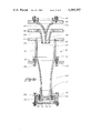
- FIG. 2 is a similar view of a fluid cyclone provided in accordance with the present invention for recovery of velocity energy
- FIG. 3 is a cross-sectional view taken along line 3--3 of FIG. 2;
- FIG. 4 is a partial elevational sectional view illustrating an alternate reject system
- FIG. 5 is a horizontal sectional view taken along essentially 5--5 of FIG. 6 of fluid cyclones of conventional type mounted in a special arrangement in accordance with the present invention
- FIG. 6 is a vertical sectional view of the multiple cyclone of FIG. 5 taken along line 6--6 of FIG. 5;
- FIG. 7 is a view similar to FIG. 6 illustrating a reject system with cyclones of the type illustrated in FIG. 2;
- FIG. 8 is an elevational view of a multi-cyclone provided in accordance with the present invention.
- FIG. 9 is an elevational view of the upper header for the multi-cyclone of FIG. 8;
- FIG. 10 is a sectional view taken along a stepped sectional line 10--10 of FIG. 11;
- FIG. 11 is a cross-sectional view taken along stepped sectional line 11--11 in FIG. 9;
- FIG. 12 is a cross-sectional view taken along stepped sectional line 12--12 in FIG. 9;
- FIG. 13 is a cross-sectional view taken along sectional lines 13--13 in FIGS. 9 and 11;
- FIG. 14 is an enlarged cross-sectional view showing in detail one of the cyclones of the multi-cyclone unit.
- FIG. 1 the most common form of hydrocyclone which is a straight conical design.
- Fluid enters by a tangential inlet 1, into a short cyclindrical section 2.
- a vortex is created in the cylindrical section and a conical section 3 below the cylindrical section as fluid spirals in a path moving downward and inward, then upward in a helical path to an exit pipe 4 co-axial with the cylindrical section.
- the centrifugal acceleration due to rapid rotation of the fluid causes dense particles to be forced outward to the wall of the cylinder and cone.
- the dense particles are transported in a slower moving boundary layer downward toward the apex 5 of the cone where they leave as a hollow cone spray.
- the high centrifugal force near the center opens up a fluid free space which is referred to as the vortex core when the fluid is a liquid.
- this cone is filled with air and a back pressure at the exit of the hydrocyclone is required to prevent air insuction.
- the present invention is directed to reducing energy losses caused by friction in fluid cyclones.
- the hydraulic energy in the fluid is mostly pressure with some as velocity.
- the tangential velocity and hence centrifuge force in the vortex of a cyclone is related to the pressure differential between the inlet and the average as the fluid leaves the central exit from the separating region.
- this average on exit is somewhere between the core pressure and the exit pressure which has to be above atmospheric pressure
- the average will again be somewhere between the core pressure and that of the outlet, but much nearer the core pressure.
- FIG. 2 A fluid cyclone with recovery of velocity energy is illustrated in FIG. 2 wherein fluid to be treated enters by a tangential nozzle inlet 10 into a cylindrical section 11. Here it mixes with fluid which has come up from below, but not left the central exit opening 12. The mixture then follows a helical form of path downward to the cone 13 which is shown as a preferred curved form although a straight form would also function.
- boundary layer material can be allowed to leave without the inner fluid by blocking the vortex with a blunt cone plate 14 while permitting the boundary layer fluid with its content of heavy material to leak away through a gap between the end 15 of the cone 13 and the blunt cone plate 14.
- the main flow inside the boundary layer is turned back upward by the restriction of cone 13 and may either rejoin the downward stream in the cylindrical section 11 or leave by the central exit 12.
- the exit channel is an annular passage 16 between an inner cone 17 and an outer cone 17A providing a space which leads gently outward and expands in area. In the design shown this passage curves outward however, although this is the preferred design as the expansion of the path is gentlest where velocity is highest, straight cones would also serve some useful purpose.
- the fluid leaves by tangential outlet 18.
- the blunt cone plate 14 blocks the vortex at the bottom and a central depressure 14A in the blunt cone plate 14 stabilizes the core.
- the rejected fluid escaping from the gap 19 between cones 13 and 14 enters a cylindrical space 20 then passes downward past the edge of the blunt cone plate 14 and spaced apart support rods 21 into a space 22 between the bottom of the blunt cone plate 14 and a bottom plate 23.
- the reject fluid will have considerable tangential velocity and pressure.
- the tangential velocity will increase such that a vortex will exist between plate 23 and the underside of the cone plate 14.
- the reject fluid will emerge finally through the central hole 24 as a hollow cone spray.
- the pressure drop across the vortex on plate 23 will limit the rejection rate in selective fashion.
- the pressure drop across a vortex occurs because of the centrifugal acceleration which acts on the mass of the fluid.
- the tangential velocity which causes this is dependent upon the initial tangential velocity of fluid entering the periphery of the vortex. If this fluid is a boundary layer fluid only, the velocity and hence throttling effect of the vortex will be low. If this fluid contains higher velocity liquid from the inner portion in cone 13, then the velocity and throttling effect of the reject vortex will be high.
- the design is hence selective in rejecting the boundary layer fluid only.
- the depth of the boundary layer will depend upon its viscosity and will increas if it contains a high content of dense solids. This same increase in viscosity will cause losses in velocity of friction in the reject vortex on plate 23, thus reducing the throttling effect permitting it to pass a higher flow. This furthers the action of the reject system making it react automatically to varying loads of undersirable material in the fluid being treated.
- FIGS. 5 and 6 there is illustrated six cyclone units 40A, 40B, 40C, 40D, 40E and 40F (only three appear in FIG. 6) that are of conventional design but provided with a novel inlet and outlet means.
- the inflow fluid to the cyclone units is from a common chamber 42 and the outflow into a common chamber 44.
- Chambers 42 and 44 are separate from one another and provided by spaced apart flat parallel plates 45, 46 and 47 interconnected by side walls and end walls.
- the chambers have respective opposite end walls 48 and 49, each of which have curved wall portions 50 and 51 interiorly of the chambers, such portions being preferably of spiral shape.
- Cyclone units 40A, 40C and 40G are spaced apart from one another in a first row and cyclone units 40B, 40D and 40F are spaced apart from one another in the second row. The first and second rows are spaced apart from another and the cyclone units are staggered as best seen from FIG. 5. Cyclone units 40A, 40C and 40G have fluid rotation which appear from top view to rotate clockwise as indicated by arrows 53, 54 and 55 whereas units 40B, 40D and 40F have fluid rotation which appears from the top view to rotate counterclockwise as indicated by arrows 56, 57 and 58.
- the row of counter-rotating units is displaced by half the distance between units in the row direction and by approximately 0.28 times the distance between units sideways, thus placing the units in the pattern normally observed in a vortex trail.
- counter-rotating vortices are closest to each other and there is no frictional shear between them.
- the individual cyclone units acquire their fluid flow, not from individual tangential inlets, but by a general pattern of multiple vortices which is established in the space 42 between the parallel plates 45 and 46.
- the pattern of flow is established by two streams of constant velocity admitted by two channels 59, one to feed fluid into clockwise vortices 53, 54 and 55 and the other into counterclockwise vortices 56, 57 and 58.
- Fluid is diverted from the channels 59 at the appropriate angle and position to form the proper spiral vortex pattern by deflection plates 60 and the spiral containment end walls 50 and 51.
- the two feed channels 59 are joined by a passage 61 having an inlet 62 thereto through which the entering fluid is fed.
- Fluid which enters the barrel of the cyclones leaves the cyclones by respective exit pipes 63 with a high rotational velocity into the space 44 between the plates 46 and 47. Although much of the rotational velocity is lost with the abrupt corner as shown, there will be reverse vortex flow in the space 44 in the tangential matrix in a similar sense to that in space 42 but with outward fluid flow movement.
- the fluid from the space 44 flows by way of two channels 64 interconnected by a passage 65 and discharged through a common outlet similar to inlet 62 illustrated in FIG. 5.
- the heavy material rejected at the bottom exit of the fluid cyclones is shown as being collected in a pan 66 and discharged through an exit passage 67.
- FIG. 7 is similar to that illustrated in FIGS. 5 and 6 and consists of a plurality of cyclone units 70 which are of the energy recovery type of FIG. 2.
- the energy recovery cyclones are arranged in the type of arrangement of FIG. 5 with the pattern of spiral vortices of a similar type created in the space between flat plates defining the chambers.
- the cyclones have conical and bottom end design 71 which is similar to that shown in FIG. 2 and an annular opening 72 for outflow of material from the cyclone.
- the annular outlet 72 leads to an expanding annular space 73 which in turn leads to space between the plates defining chamber 74. In this latter space the reverse spiral flow pattern described above with reference to FIGS.
- Material to the respective cyclone units 70 is from a chamber 79 common to all of the units and having a pair of inlet passage means 80 (only one of which is shown) similar to the passages 59 described and illustrated with reference to FIG. 5.
- the pair of passages 80 are interconnected by a passage 81 having an inlet thereto (not shown) corresponding to inlet 62 illustrated and described with reference to FIG. 5.
- FIGS. 8 to 14 inclusive there is illustrated in more detail a practical embodiment of a multicyclone unit consisting of a plurality of individual cyclone units 100 having an inlet and outlet header system 200 on the upper end and a reject box 300 on the lower end, all of which are mounted on a supporting structure 400.
- the supporting frame consists of four vertical posts 401 rigidly connected by way of coupling members 402 to a horizontally disposed support plate 403.
- the reject box 300 is also rigidly connected to the legs 401 by way of bracket members 301, further rigidifying the entire structure.
- the header 200 has an inlet 201 for fluids to be treated and an outlet 202. Details of the header 200 are illustrated in FIGS. 9 to 13 inclusive and reference will now be made thereto.
- the header 200 is a rigid assembly having four sockets 203 for receiving the upper ends of the frame posts 401, thereby mounting the header on the frame. Suitable locking means, for example set screws or the like, may be utilized in anchoring the header to the posts.
- the header 200 has a chamber 204 in which there is established a pattern of vortex flow such that the chamber serves as a common inlet for all of the cyclone units. Similarly there is a chamber 205 common to all of the individual cyclone units for the outflow of fluid from the cyclones.
- the inlet chamber 204 is defined by a central plate 206 and a lower plate 207 together with side plates 208 and 209.
- the outlet chamber is defined by the central plate 206 and upper plate 210 spaced therefrom and the side plates 208 and 209.
- a partition wall 212 that divides the inflowing fluid into two passages designated respectively 213 and 214.
- diverter plates 215 and 216 secured to the central plate 206 and projecting downwardly therefrom toward the lower wall of the inlet manifold but spaced therefrom.
- the diverter plates 215 and 216 direct the inflowing fluid to form spiral vortices about the inlets of respective individual cyclone units 100A and 100B. Fluid flowing below the diverter plates 215 and 216 is directed to form spiral vortices about the respective individual cyclone units 100C and 100D.
- the curved end wall portions 221, 222, 223 and 224 serve as containment walls for the vortices at respective cyclone units 100A, 100B, 100C and 100D and as previously mentioned are preferably spirally shaped.
- the passages in outlet chamber 205 are shown in FIG. 12 which is a section taken along stepped line 12--12 in FIG. 9. The outlet from the individual cyclone units 100A, 100B, 100C and 100D is into chamber 205 and fluid flow therefrom is divided by partition wall 217 into passages 218 and 219 connected by way of passage 220 to the outlet 202.
- FIG. 14 A cross-section of an individual cyclone unit is illustrated in FIG. 14 and includes an upper cylindrical portion 101 followed by a lower tapered conical section 102.
- Inflow of fluid to be treated through chamber 204 enters the cyclone from the centre of the spiral vortex in said manifold by annular inlet passage 103.
- Outflow from the cyclone is through an annular passage 104, gradually increasing in size to the outlet chamber 205 where it spirals outward.
- the passage 104 is provided by truncated conical member 105 mounted on the intermediate plate 206 and a further conical member 106 projecting thereinto and mounted on the upper plate 210 by a plurality of bolts 107.
- the cylindrical portion 101 and tapered lower end portion 102 may be a single unit or, alternatively, separate units as illustrated, the cylindrical portion being provided by a short length of sleeve abutting at one end the lower manifold plate 207 and at the other end a flange on the tapered cone 102.
- O-ring seals 110 are provided to seal the joints.
- the reject box 300 is mounted on the frame posts 401 at the lower reject outlet end of the cyclone. Between the reject box and mounted on the lower end of the conical portion are upper and lower plates 120 and 121 interconnected by a plurality of bolt and nut units 122 and held in spaced apart relation by a short sleeve 123.
- the lower end of the cone 102 is open as indicated at 112 and spaced therebelow is a cone plate 125.
- the cone plate 125 is mounted on the plate 120 by a plurality of machine screws 126 spaced apart from one another circumferentially around the cone plate.
- the cone plate is held in suitable spaced relation from plate 120 by spacers 127. Rejects from the cyclone follow the path indicated by the arrow A and discharge into the reject header box 300 by way of an aperture 128 in the lower plate 121.
- Cyclones of the foregoing design are basically intended for use with water as the working fluid.
- the present design is also deemed applicable when using gas as the working fluid; for example, treating gases from furnaces to remove fly ash and smoke.
- a small multi-cyclone unit as described in the foregoing has been tested by the applicant for comparison in operability with air as opposed to water as the working fluid.
- a fan was used to suck the air through the unit.
- the comparison makes the assumption that friction losses are proportional to velocity head whether one is dealing with air or water which is approximately true at very high Reynolds number.
- the following table shows comparative operation of the system on water and air:
- Hydraulic capacities are roughly proportional to the square root of the applied pressure differential.
- Mean gravities will be roughly proportional to the pressure differential.
- the mean pressure shown is in the fluid leaving the interior of the unit. The very center of the vortex will have a much lower pressure which in the case of water is filled with water vapour. The core condition with air is difficult to estimate due to expansion of the gas resulting in reduced density and temperature.
Abstract
Description
______________________________________
         PRESSURE P.S.I.
                      VELOCITY
         CONVENTIONAL RECOVERY
PRESSURE   IN-    OUT-          IN-  OUT-
DIFFERENCE LET    LET     CORE  LET  LET   CORE
______________________________________
High       50     5       0     40   10    -15
Low        20     5       0      5    0    -15
______________________________________
______________________________________COMPARSION 3" MULTICYLONE 4 UNITS Water Air______________________________________ Inlet Pressure 10 p.s.i. Atmospheric Outlet Pressure 0 p.s.i. -1" Water Gauge Flow 150 US gallon/min 62 cubic ft/min Mean Gravities 315 975 Mean Pressure at 6" Hg Vacuum -1.2" Water gauge Outlet Core Pressure 28"High Vacuum 10" Hg Vacuum? ______________________________________
Claims (17)
Priority Applications (6)
| Application Number | Priority Date | Filing Date | Title |
|---|---|---|---|
| US06/275,987 US4389307A (en) | 1981-06-22 | 1981-06-22 | Arrangement of multiple fluid cyclones |
| CA000405038A CA1218962A (en) | 1981-06-22 | 1982-06-11 | Arrangement of multiple fluid cyclones |
| EP82303242A EP0068792B1 (en) | 1981-06-22 | 1982-06-22 | Arrangement of multiple fluid cyclones |
| DE8282303242T DE3279026D1 (en) | 1981-06-22 | 1982-06-22 | Arrangement of multiple fluid cyclones |
| CA000482396A CA1212924A (en) | 1981-06-22 | 1985-05-24 | Streamlined vortical inlet and outlet header for hydrocyclone banks |
| US07/089,262 US4842145A (en) | 1981-06-22 | 1987-08-25 | Arrangement of multiple fluid cyclones |
Applications Claiming Priority (1)
| Application Number | Priority Date | Filing Date | Title |
|---|---|---|---|
| US06/275,987 US4389307A (en) | 1981-06-22 | 1981-06-22 | Arrangement of multiple fluid cyclones |
Related Child Applications (1)
| Application Number | Title | Priority Date | Filing Date |
|---|---|---|---|
| US47347983A Division | 1983-03-09 | 1983-03-09 |
Publications (1)
| Publication Number | Publication Date |
|---|---|
| US4389307A true US4389307A (en) | 1983-06-21 |
Family
ID=23054658
Family Applications (1)
| Application Number | Title | Priority Date | Filing Date |
|---|---|---|---|
| US06/275,987 Expired - Fee Related US4389307A (en) | 1981-06-22 | 1981-06-22 | Arrangement of multiple fluid cyclones |
Country Status (4)
| Country | Link |
|---|---|
| US (1) | US4389307A (en) |
| EP (1) | EP0068792B1 (en) |
| CA (1) | CA1218962A (en) |
| DE (1) | DE3279026D1 (en) |
Cited By (24)
| Publication number | Priority date | Publication date | Assignee | Title |
|---|---|---|---|---|
| US4537608A (en) * | 1983-11-16 | 1985-08-27 | Pall Corporation | System for removing contaminant particles from a gas |
| US4702846A (en) * | 1983-01-21 | 1987-10-27 | Nobar Ky | Method of and apparatus for sequentially separating a medium into different components |
| US4842145A (en) * | 1981-06-22 | 1989-06-27 | B.W.N. Vortoil Rights Co. Pty. Ltd. | Arrangement of multiple fluid cyclones |
| US4976875A (en) * | 1986-02-12 | 1990-12-11 | Lisop Oy | Method of and apparatus for separating a medium in different components by means of gravity |
| US5009785A (en) * | 1985-04-23 | 1991-04-23 | Conoco Specialty Products Inc. | System and apparatus for the separation of multi-phase mixture |
| US5045218A (en) * | 1986-11-26 | 1991-09-03 | Delawood Pty. Ltd. | Method of separating a lighter dispersed fluid from a denser liquid in a hydrocyclone having flow-modifying means |
| US5106514A (en) * | 1990-05-11 | 1992-04-21 | Mobil Oil Corporation | Material extraction nozzle |
| US5221476A (en) * | 1990-07-31 | 1993-06-22 | Bird Escher Wyss Inc. | Hydrocyclone conduits |
| US5246575A (en) * | 1990-05-11 | 1993-09-21 | Mobil Oil Corporation | Material extraction nozzle coupled with distillation tower and vapors separator |
| US5667686A (en) * | 1995-10-24 | 1997-09-16 | United States Filter Corporation | Hydrocyclone for liquid - liquid separation and method |
| GB2376196A (en) * | 2001-05-29 | 2002-12-11 | Samsung Kwangju Electronics Co | Cyclone dust collecting apparatus for vacuum cleaners |
| US20030227258A1 (en) * | 2000-08-10 | 2003-12-11 | Strang Eric J. | Method and apparatus for tuning a plasma reactor chamber |
| US6758343B1 (en) * | 1999-06-02 | 2004-07-06 | Weir Slurry Group, Inc. | Dual hydro-cyclone with water injection |
| US6800208B2 (en) | 2003-01-10 | 2004-10-05 | United States Filter Corporation | Hydrocyclone bundle |
| US20080011692A1 (en) * | 2006-07-14 | 2008-01-17 | Siemens Vdo Automotive Corporation | Cyclonic particle separator for fuel systems |
| US20080169237A1 (en) * | 2007-01-12 | 2008-07-17 | The Eliminator Tank & Oilfield Rentals Ltd. | Apparatus for separating solids from liquids |
| US20080290002A1 (en) * | 2005-11-10 | 2008-11-27 | Siegfried Strasser | Safety Device for Sieving Granular Material |
| CN103008122A (en) * | 2012-12-28 | 2013-04-03 | 刘晔 | Swirler |
| WO2013082118A1 (en) * | 2011-11-29 | 2013-06-06 | Taper-Lok Corporation | Systems and methods for separating sand from oil |
| US20180161701A1 (en) * | 2015-06-25 | 2018-06-14 | Tomle Strategies Pty Ltd | Multi-stage separation device for use with flowable system of substances |
| CN112691798A (en) * | 2019-10-22 | 2021-04-23 | 中国石油化工股份有限公司 | Cyclone separator, application method thereof and fluidized bed reactor |
| US11015156B1 (en) * | 2020-05-22 | 2021-05-25 | Franzenburg | Protein concentration methods |
| EP4124389A1 (en) * | 2021-07-27 | 2023-02-01 | Siebec | System for filtering an aerosol by means of a plurality of cyclone-effect separators and filtering method |
| US11746312B1 (en) * | 2019-05-31 | 2023-09-05 | Separator Technology Solutions Us Inc. | Stillage clarification |
Families Citing this family (70)
| Publication number | Priority date | Publication date | Assignee | Title |
|---|---|---|---|---|
| EP0287721A3 (en) * | 1987-04-22 | 1990-03-07 | Conoco Specialty Products Inc. | Cyclone separator |
| MY112609A (en) * | 1994-12-21 | 2001-07-31 | Dyson Technology Ltd | Improved dust separation apparatus |
| SE9500091L (en) * | 1995-01-12 | 1996-07-13 | Abb Carbon Ab | dust Cleaner |
| US5893938A (en) * | 1995-12-20 | 1999-04-13 | Notetry Limited | Dust separation apparatus |
| US7803207B2 (en) | 2006-03-10 | 2010-09-28 | G.B.D. Corp. | Vacuum cleaner with a divider |
| GB2457420B (en) | 2006-12-12 | 2012-01-04 | Gbd Corp | Convertible surface cleaning apparatus |
| US10765277B2 (en) | 2006-12-12 | 2020-09-08 | Omachron Intellectual Property Inc. | Configuration of a surface cleaning apparatus |
| US8950039B2 (en) | 2009-03-11 | 2015-02-10 | G.B.D. Corp. | Configuration of a surface cleaning apparatus |
| US10165912B2 (en) | 2006-12-15 | 2019-01-01 | Omachron Intellectual Property Inc. | Surface cleaning apparatus |
| US11857142B2 (en) | 2006-12-15 | 2024-01-02 | Omachron Intellectual Property Inc. | Surface cleaning apparatus having an energy storage member and a charger for an energy storage member |
| US20210401246A1 (en) | 2016-04-11 | 2021-12-30 | Omachron Intellectual Property Inc. | Surface cleaning apparatus |
| US9888817B2 (en) | 2014-12-17 | 2018-02-13 | Omachron Intellectual Property Inc. | Surface cleaning apparatus |
| US9192269B2 (en) | 2006-12-15 | 2015-11-24 | Omachron Intellectual Property Inc. | Surface cleaning apparatus |
| US11751733B2 (en) | 2007-08-29 | 2023-09-12 | Omachron Intellectual Property Inc. | Portable surface cleaning apparatus |
| US10722086B2 (en) | 2017-07-06 | 2020-07-28 | Omachron Intellectual Property Inc. | Handheld surface cleaning apparatus |
| US11690489B2 (en) | 2009-03-13 | 2023-07-04 | Omachron Intellectual Property Inc. | Surface cleaning apparatus with an external dirt chamber |
| CA2674761C (en) | 2009-03-13 | 2016-10-04 | G.B.D. Corp. | Surface cleaning apparatus with different cleaning configurations |
| US11612288B2 (en) | 2009-03-13 | 2023-03-28 | Omachron Intellectual Property Inc. | Surface cleaning apparatus |
| US9265395B2 (en) | 2010-03-12 | 2016-02-23 | Omachron Intellectual Property Inc. | Surface cleaning apparatus |
| US9211044B2 (en) | 2011-03-04 | 2015-12-15 | Omachron Intellectual Property Inc. | Compact surface cleaning apparatus |
| US9433332B2 (en) | 2013-02-27 | 2016-09-06 | Omachron Intellectual Property Inc. | Surface cleaning apparatus |
| CA2967272C (en) | 2009-03-13 | 2018-01-02 | Omachron Intellectual Property Inc. | Hand vacuum cleaner |
| US8640304B2 (en) | 2010-03-12 | 2014-02-04 | G.B.D. Corp. | Cyclone construction for a surface cleaning apparatus |
| US8875340B2 (en) | 2010-03-12 | 2014-11-04 | G.B.D. Corp. | Surface cleaning apparatus with enhanced operability |
| US9320401B2 (en) | 2013-02-27 | 2016-04-26 | Omachron Intellectual Property Inc. | Surface cleaning apparatus |
| US9591958B2 (en) | 2013-02-27 | 2017-03-14 | Omachron Intellectual Property Inc. | Surface cleaning apparatus |
| US9295995B2 (en) | 2013-02-28 | 2016-03-29 | Omachron Intellectual Property Inc. | Cyclone such as for use in a surface cleaning apparatus |
| US9227201B2 (en) | 2013-02-28 | 2016-01-05 | Omachron Intellectual Property Inc. | Cyclone such as for use in a surface cleaning apparatus |
| US20140237764A1 (en) | 2013-02-28 | 2014-08-28 | G.B.D. Corp. | Cyclone such as for use in a surface cleaning apparatus |
| US9326652B2 (en) | 2013-02-28 | 2016-05-03 | Omachron Intellectual Property Inc. | Surface cleaning apparatus |
| US9820621B2 (en) | 2013-02-28 | 2017-11-21 | Omachron Intellectual Property Inc. | Surface cleaning apparatus |
| US9451855B2 (en) | 2013-02-28 | 2016-09-27 | Omachron Intellectual Property Inc. | Surface cleaning apparatus |
| US9227151B2 (en) | 2013-02-28 | 2016-01-05 | Omachron Intellectual Property Inc. | Cyclone such as for use in a surface cleaning apparatus |
| US9215960B2 (en) | 2013-02-28 | 2015-12-22 | Omachron Intellectual Property Inc. | Surface cleaning apparatus |
| US9456721B2 (en) | 2013-02-28 | 2016-10-04 | Omachron Intellectual Property Inc. | Surface cleaning apparatus |
| US9238235B2 (en) | 2013-02-28 | 2016-01-19 | Omachron Intellectual Property Inc. | Cyclone such as for use in a surface cleaning apparatus |
| US9314139B2 (en) | 2014-07-18 | 2016-04-19 | Omachron Intellectual Property Inc. | Portable surface cleaning apparatus |
| US9451853B2 (en) | 2014-07-18 | 2016-09-27 | Omachron Intellectual Property Inc. | Portable surface cleaning apparatus |
| US9420925B2 (en) | 2014-07-18 | 2016-08-23 | Omachron Intellectual Property Inc. | Portable surface cleaning apparatus |
| US9585530B2 (en) | 2014-07-18 | 2017-03-07 | Omachron Intellectual Property Inc. | Portable surface cleaning apparatus |
| US11950745B2 (en) | 2014-12-17 | 2024-04-09 | Omachron Intellectual Property Inc. | Surface cleaning apparatus |
| US10251519B2 (en) | 2014-12-17 | 2019-04-09 | Omachron Intellectual Property Inc. | Surface cleaning apparatus |
| US10136778B2 (en) | 2014-12-17 | 2018-11-27 | Omachron Intellectual Property Inc. | Surface cleaning apparatus |
| US10292550B2 (en) | 2016-08-29 | 2019-05-21 | Omachron Intellectual Property Inc. | Surface cleaning apparatus |
| US10433689B2 (en) | 2016-08-29 | 2019-10-08 | Omachron Intellectual Property Inc. | Surface cleaning apparatus |
| US10441124B2 (en) | 2016-08-29 | 2019-10-15 | Omachron Intellectual Property Inc. | Surface cleaning apparatus |
| US10413141B2 (en) | 2016-08-29 | 2019-09-17 | Omachron Intellectual Property Inc. | Surface cleaning apparatus |
| US10136779B2 (en) | 2016-08-29 | 2018-11-27 | Omachron Intellectual Property Inc. | Surface cleaning apparatus |
| US10441125B2 (en) | 2016-08-29 | 2019-10-15 | Omachron Intellectual Property Inc. | Surface cleaning apparatus |
| US10729295B2 (en) | 2016-08-29 | 2020-08-04 | Omachron Intellectual Property Inc. | Surface cleaning apparatus |
| US10405711B2 (en) | 2016-08-29 | 2019-09-10 | Omachron Intellectual Property Inc. | Surface cleaning apparatus |
| US11478117B2 (en) | 2016-08-29 | 2022-10-25 | Omachron Intellectual Property Inc. | Surface cleaning apparatus |
| US10321794B2 (en) | 2016-08-29 | 2019-06-18 | Omachron Intellectual Property Inc. | Surface cleaning apparatus |
| US10136780B2 (en) | 2016-08-29 | 2018-11-27 | Omachron Intellectual Property Inc. | Surface cleaning apparatus |
| US9962050B2 (en) | 2016-08-29 | 2018-05-08 | Omachron Intellectual Property Inc. | Surface cleaning apparatus |
| US11766156B2 (en) | 2020-03-18 | 2023-09-26 | Omachron Intellectual Property Inc. | Surface cleaning apparatus with removable air treatment member assembly |
| US10702113B2 (en) | 2017-07-06 | 2020-07-07 | Omachron Intellectual Property Inc. | Handheld surface cleaning apparatus |
| US11445878B2 (en) | 2020-03-18 | 2022-09-20 | Omachron Intellectual Property Inc. | Surface cleaning apparatus with removable air treatment member assembly |
| US10631693B2 (en) | 2017-07-06 | 2020-04-28 | Omachron Intellectual Property Inc. | Handheld surface cleaning apparatus |
| US10506904B2 (en) | 2017-07-06 | 2019-12-17 | Omachron Intellectual Property Inc. | Handheld surface cleaning apparatus |
| US10537216B2 (en) | 2017-07-06 | 2020-01-21 | Omachron Intellectual Property Inc. | Handheld surface cleaning apparatus |
| US11666193B2 (en) | 2020-03-18 | 2023-06-06 | Omachron Intellectual Property Inc. | Surface cleaning apparatus with removable air treatment member assembly |
| US11730327B2 (en) | 2020-03-18 | 2023-08-22 | Omachron Intellectual Property Inc. | Surface cleaning apparatus with removable air treatment assembly |
| US10842330B2 (en) | 2017-07-06 | 2020-11-24 | Omachron Intellectual Property Inc. | Handheld surface cleaning apparatus |
| US10750913B2 (en) | 2017-07-06 | 2020-08-25 | Omachron Intellectual Property Inc. | Handheld surface cleaning apparatus |
| US11013378B2 (en) | 2018-04-20 | 2021-05-25 | Omachon Intellectual Property Inc. | Surface cleaning apparatus |
| US11013384B2 (en) | 2018-08-13 | 2021-05-25 | Omachron Intellectual Property Inc. | Cyclonic air treatment member and surface cleaning apparatus including the same |
| US11006799B2 (en) | 2018-08-13 | 2021-05-18 | Omachron Intellectual Property Inc. | Cyclonic air treatment member and surface cleaning apparatus including the same |
| US11192122B2 (en) | 2018-08-13 | 2021-12-07 | Omachron Intellectual Property Inc. | Cyclonic air treatment member and surface cleaning apparatus including the same |
| HUE059649T2 (en) * | 2018-12-12 | 2022-12-28 | Filtra Group Oy | Device and method for fluid purification |
Citations (7)
| Publication number | Priority date | Publication date | Assignee | Title |
|---|---|---|---|---|
| AT149985B (en) * | 1936-05-30 | 1937-06-25 | Eugen Dr Feifel | Device for separating physical mixtures. |
| US2532885A (en) * | 1947-04-11 | 1950-12-05 | Berges Andre Charles | Vortex type separator for paper pulp |
| US3415373A (en) * | 1964-08-31 | 1968-12-10 | Pink Peter | Particle size classification method and apparatus |
| US3458237A (en) * | 1967-08-29 | 1969-07-29 | Melpar Inc | Solid particulate metering system |
| US3613887A (en) * | 1968-10-14 | 1971-10-19 | Nils Anders Lennart Wikdahl | Clyclone separator to be built in a casing or similar |
| US3948771A (en) * | 1973-11-30 | 1976-04-06 | Messerschmitt-Bolkow-Blohm Gmbh | Method and apparatus for separating suspended matter from a fluid by centrifugal force |
| US4001121A (en) * | 1971-12-06 | 1977-01-04 | Messerschmitt-Bolkow-Blohm Gmbh - Division Hamburger Flugzeugbau | Centrifugal treatment of fluids |
Family Cites Families (9)
| Publication number | Priority date | Publication date | Assignee | Title |
|---|---|---|---|---|
| GB260776A (en) * | 1925-11-05 | 1926-11-11 | Wilfred Rothery Wood | Improvements in cyclone separators or driers |
| US1886548A (en) * | 1929-04-22 | 1932-11-08 | Int Precipitation Co | Means for treating gases |
| GB692210A (en) * | 1949-09-20 | 1953-06-03 | Babcock & Wilcox Ltd | Improvements in plant for extracting dust from gas |
| NL181479C (en) * | 1952-09-24 | |||
| US2963109A (en) * | 1957-02-11 | 1960-12-06 | Roger S Brookman | Centrifugal type separating apparatus |
| US2982409A (en) * | 1958-06-10 | 1961-05-02 | Nichols Engineering And Res Co | Separation of foam and other materials from liquid mixtures |
| US3421622A (en) * | 1965-08-19 | 1969-01-14 | Nichols Eng & Res Corp | Cleaning and deaerating paper pulp suspensions |
| US3720253A (en) * | 1971-04-02 | 1973-03-13 | Ballas Egg Prod Corp | Egg white spray drying apparatus and method |
| AU470888B2 (en) * | 1971-12-09 | 1976-04-01 | State Electricity Commission Of Victoria | Improvements in and relating to stream dividers |
-
1981
- 1981-06-22 US US06/275,987 patent/US4389307A/en not_active Expired - Fee Related
-
1982
- 1982-06-11 CA CA000405038A patent/CA1218962A/en not_active Expired
- 1982-06-22 EP EP82303242A patent/EP0068792B1/en not_active Expired
- 1982-06-22 DE DE8282303242T patent/DE3279026D1/en not_active Expired
Patent Citations (8)
| Publication number | Priority date | Publication date | Assignee | Title |
|---|---|---|---|---|
| AT149985B (en) * | 1936-05-30 | 1937-06-25 | Eugen Dr Feifel | Device for separating physical mixtures. |
| US2532885A (en) * | 1947-04-11 | 1950-12-05 | Berges Andre Charles | Vortex type separator for paper pulp |
| US3415373A (en) * | 1964-08-31 | 1968-12-10 | Pink Peter | Particle size classification method and apparatus |
| US3458237A (en) * | 1967-08-29 | 1969-07-29 | Melpar Inc | Solid particulate metering system |
| US3613887A (en) * | 1968-10-14 | 1971-10-19 | Nils Anders Lennart Wikdahl | Clyclone separator to be built in a casing or similar |
| US3613887B1 (en) * | 1968-10-14 | 1988-08-30 | ||
| US4001121A (en) * | 1971-12-06 | 1977-01-04 | Messerschmitt-Bolkow-Blohm Gmbh - Division Hamburger Flugzeugbau | Centrifugal treatment of fluids |
| US3948771A (en) * | 1973-11-30 | 1976-04-06 | Messerschmitt-Bolkow-Blohm Gmbh | Method and apparatus for separating suspended matter from a fluid by centrifugal force |
Cited By (37)
| Publication number | Priority date | Publication date | Assignee | Title |
|---|---|---|---|---|
| US4842145A (en) * | 1981-06-22 | 1989-06-27 | B.W.N. Vortoil Rights Co. Pty. Ltd. | Arrangement of multiple fluid cyclones |
| US4702846A (en) * | 1983-01-21 | 1987-10-27 | Nobar Ky | Method of and apparatus for sequentially separating a medium into different components |
| US4820427A (en) * | 1983-01-21 | 1989-04-11 | Nobar Ky | Method of sequentially separating a medium into different components |
| US4537608A (en) * | 1983-11-16 | 1985-08-27 | Pall Corporation | System for removing contaminant particles from a gas |
| US5009785A (en) * | 1985-04-23 | 1991-04-23 | Conoco Specialty Products Inc. | System and apparatus for the separation of multi-phase mixture |
| US4976875A (en) * | 1986-02-12 | 1990-12-11 | Lisop Oy | Method of and apparatus for separating a medium in different components by means of gravity |
| US5045218A (en) * | 1986-11-26 | 1991-09-03 | Delawood Pty. Ltd. | Method of separating a lighter dispersed fluid from a denser liquid in a hydrocyclone having flow-modifying means |
| US5106514A (en) * | 1990-05-11 | 1992-04-21 | Mobil Oil Corporation | Material extraction nozzle |
| US5246575A (en) * | 1990-05-11 | 1993-09-21 | Mobil Oil Corporation | Material extraction nozzle coupled with distillation tower and vapors separator |
| US5221476A (en) * | 1990-07-31 | 1993-06-22 | Bird Escher Wyss Inc. | Hydrocyclone conduits |
| US5667686A (en) * | 1995-10-24 | 1997-09-16 | United States Filter Corporation | Hydrocyclone for liquid - liquid separation and method |
| US6758343B1 (en) * | 1999-06-02 | 2004-07-06 | Weir Slurry Group, Inc. | Dual hydro-cyclone with water injection |
| US6960887B2 (en) * | 2000-08-10 | 2005-11-01 | Tokyo Electron Limited | Method and apparatus for tuning a plasma reactor chamber |
| US20030227258A1 (en) * | 2000-08-10 | 2003-12-11 | Strang Eric J. | Method and apparatus for tuning a plasma reactor chamber |
| GB2376196B (en) * | 2001-05-29 | 2003-08-13 | Samsung Kwangju Electronics Co | Cyclone dust-collecting apparatus for vacuum cleaner |
| US6596047B2 (en) | 2001-05-29 | 2003-07-22 | Samsung Gwangju Electronics Co., Ltd. | Cyclone dust collecting apparatus for a vacuum cleaner |
| GB2376196A (en) * | 2001-05-29 | 2002-12-11 | Samsung Kwangju Electronics Co | Cyclone dust collecting apparatus for vacuum cleaners |
| US6800208B2 (en) | 2003-01-10 | 2004-10-05 | United States Filter Corporation | Hydrocyclone bundle |
| US20050230327A1 (en) * | 2003-01-10 | 2005-10-20 | Steven Bolman | Hydrocyclone bundle |
| US7291268B2 (en) | 2003-01-10 | 2007-11-06 | Siemens Water Technologies Holding Corp. | Hydrocyclone bundle |
| US8083070B2 (en) * | 2005-11-10 | 2011-12-27 | Khd Humboldt Wedag Gmbh | Screening device for sieving granular material |
| US20080290002A1 (en) * | 2005-11-10 | 2008-11-27 | Siegfried Strasser | Safety Device for Sieving Granular Material |
| US7524426B2 (en) | 2006-07-14 | 2009-04-28 | Continental Automotive Systems Us, Inc. | Cyclonic particle separator for fuel systems |
| US20080011692A1 (en) * | 2006-07-14 | 2008-01-17 | Siemens Vdo Automotive Corporation | Cyclonic particle separator for fuel systems |
| WO2008008313A1 (en) * | 2006-07-14 | 2008-01-17 | Continental Automotive Systems Us, Inc. | Cyclonic particle separator for fuel systems |
| US20080169237A1 (en) * | 2007-01-12 | 2008-07-17 | The Eliminator Tank & Oilfield Rentals Ltd. | Apparatus for separating solids from liquids |
| US8945399B2 (en) | 2011-11-29 | 2015-02-03 | Taper-Lok Corporation | Systems and methods for separating sand from oil |
| WO2013082118A1 (en) * | 2011-11-29 | 2013-06-06 | Taper-Lok Corporation | Systems and methods for separating sand from oil |
| CN103008122B (en) * | 2012-12-28 | 2016-02-03 | 刘晔 | Cyclone |
| CN103008122A (en) * | 2012-12-28 | 2013-04-03 | 刘晔 | Swirler |
| US20180161701A1 (en) * | 2015-06-25 | 2018-06-14 | Tomle Strategies Pty Ltd | Multi-stage separation device for use with flowable system of substances |
| US11746312B1 (en) * | 2019-05-31 | 2023-09-05 | Separator Technology Solutions Us Inc. | Stillage clarification |
| CN112691798A (en) * | 2019-10-22 | 2021-04-23 | 中国石油化工股份有限公司 | Cyclone separator, application method thereof and fluidized bed reactor |
| CN112691798B (en) * | 2019-10-22 | 2022-11-15 | 中国石油化工股份有限公司 | Cyclone separator, application method thereof and fluidized bed reactor |
| US11015156B1 (en) * | 2020-05-22 | 2021-05-25 | Franzenburg | Protein concentration methods |
| EP4124389A1 (en) * | 2021-07-27 | 2023-02-01 | Siebec | System for filtering an aerosol by means of a plurality of cyclone-effect separators and filtering method |
| FR3125729A1 (en) * | 2021-07-27 | 2023-02-03 | Siebec | SYSTEM FOR FILTRATION OF AN AEROSOL BY MEANS OF A PLURALITY OF SEPARATORS BY CYCLONE EFFECT AND METHOD OF FILTRATION |
Also Published As
| Publication number | Publication date |
|---|---|
| EP0068792A3 (en) | 1985-02-06 |
| EP0068792A2 (en) | 1983-01-05 |
| CA1218962A (en) | 1987-03-10 |
| DE3279026D1 (en) | 1988-10-20 |
| EP0068792B1 (en) | 1988-09-14 |
Similar Documents
| Publication | Publication Date | Title |
|---|---|---|
| US4389307A (en) | Arrangement of multiple fluid cyclones | |
| US3641745A (en) | Gas liquid separator | |
| US3725271A (en) | Apparatus and method for separating particles from a flow of fluid | |
| US4378289A (en) | Method and apparatus for centrifugal separation | |
| US4187089A (en) | Horizontal vapor-liquid separator | |
| US1735298A (en) | Apparatus for collecting dust particles | |
| EP2106297B2 (en) | Device and method for separating a flowing medium mixture with a stationary cyclone | |
| KR890000527B1 (en) | Cyclone separators | |
| US4278550A (en) | Fluid separator | |
| US5104520A (en) | Apparatus and method for separating constituents | |
| US3800946A (en) | Hydrocyclones | |
| US3590558A (en) | Particle-from-fluid separator | |
| US4755194A (en) | Method for introducing a mixture of gas and liquid into a separator vessel | |
| US3597901A (en) | Gas scrubber, entrainment separator and combination thereof | |
| US4581142A (en) | Hydrocyclone | |
| US3638925A (en) | Adjustable annular venturi scrubber | |
| US4473478A (en) | Cyclone separators | |
| US3767174A (en) | Gas scrubber, entrainment separator and combination thereof | |
| JPH0718110B2 (en) | Purifier for paper pulp | |
| US3335860A (en) | Centrifugal cleaner for paper making stock and the like | |
| HU184588B (en) | Method and apparatus for separating medium into components of different density | |
| US1930476A (en) | Line separator and grader | |
| US3716137A (en) | Cyclone separator | |
| US3881900A (en) | Gas liquid separator | |
| US3893922A (en) | Cylindrical cyclone centrifuges |
Legal Events
| Date | Code | Title | Description |
|---|---|---|---|
| AS | Assignment |
Owner name: QUEEN'S UNIVERSITY AT KINGSTON, KINGSTON, ONTARIO, Free format text: ASSIGNMENT OF ASSIGNORS INTEREST.;ASSIGNOR:BOADWAY, JOHN D.;REEL/FRAME:003896/0883 Effective date: 19810610 |
|
| MAFP | Maintenance fee payment |
Free format text: PAYMENT OF MAINTENANCE FEE, 4TH YEAR, PL 96-517 (ORIGINAL EVENT CODE: M170); ENTITY STATUS OF PATENT OWNER: SMALL ENTITY Year of fee payment: 4 |
|
| FEPP | Fee payment procedure |
Free format text: PAYOR NUMBER ASSIGNED (ORIGINAL EVENT CODE: ASPN); ENTITY STATUS OF PATENT OWNER: SMALL ENTITY |
|
| AS | Assignment |
Owner name: B.W.N. VORTOIL RIGHTS CO. PTY. LTD., 4 PARK DRIVE, Free format text: ASSIGNMENT OF ASSIGNORS INTEREST.;ASSIGNOR:QUEEN'S UNIVERSITY AT KINGSTON;REEL/FRAME:004843/0065 Effective date: 19870618 Owner name: B.W.N. VORTOIL RIGHTS CO. PTY. LTD.,AUSTRALIA Free format text: ASSIGNMENT OF ASSIGNORS INTEREST;ASSIGNOR:QUEEN'S UNIVERSITY AT KINGSTON;REEL/FRAME:004843/0065 Effective date: 19870618 |
|
| AS | Assignment |
Owner name: CONOCO SPECIALTY PRODUCTS INC., TEXAS Free format text: ASSIGNMENT OF ASSIGNORS INTEREST.;ASSIGNOR:QUEEN'S UNIVERSITY AT KINGSTON;REEL/FRAME:005253/0008 Effective date: 19890821 |
|
| FEPP | Fee payment procedure |
Free format text: PAYOR NUMBER ASSIGNED (ORIGINAL EVENT CODE: ASPN); ENTITY STATUS OF PATENT OWNER: SMALL ENTITY Free format text: PAYER NUMBER DE-ASSIGNED (ORIGINAL EVENT CODE: RMPN); ENTITY STATUS OF PATENT OWNER: SMALL ENTITY |
|
| MAFP | Maintenance fee payment |
Free format text: PAYMENT OF MAINTENANCE FEE, 8TH YEAR, PL 96-517 (ORIGINAL EVENT CODE: M171); ENTITY STATUS OF PATENT OWNER: SMALL ENTITY Year of fee payment: 8 |
|
| FEPP | Fee payment procedure |
Free format text: MAINTENANCE FEE REMINDER MAILED (ORIGINAL EVENT CODE: REM.); ENTITY STATUS OF PATENT OWNER: SMALL ENTITY |
|
| LAPS | Lapse for failure to pay maintenance fees | ||
| FP | Lapsed due to failure to pay maintenance fee |
Effective date: 19950621 |
|
| STCH | Information on status: patent discontinuation |
Free format text: PATENT EXPIRED DUE TO NONPAYMENT OF MAINTENANCE FEES UNDER 37 CFR 1.362 |