EP1995200B2 - Procédé et dispositif de fonctionnement d'un dispositif de bobinage d'une machine textile produisant des bobines croisées - Google Patents
Procédé et dispositif de fonctionnement d'un dispositif de bobinage d'une machine textile produisant des bobines croisées Download PDFInfo
- Publication number
- EP1995200B2 EP1995200B2 EP08007077.4A EP08007077A EP1995200B2 EP 1995200 B2 EP1995200 B2 EP 1995200B2 EP 08007077 A EP08007077 A EP 08007077A EP 1995200 B2 EP1995200 B2 EP 1995200B2
- Authority
- EP
- European Patent Office
- Prior art keywords
- thread
- bobbin
- cross
- wound
- wound bobbin
- Prior art date
- Legal status (The legal status is an assumption and is not a legal conclusion. Google has not performed a legal analysis and makes no representation as to the accuracy of the status listed.)
- Active
Links
- 238000004804 winding Methods 0.000 title claims description 62
- 238000000034 method Methods 0.000 title claims description 25
- 239000004753 textile Substances 0.000 title claims description 13
- 238000003860 storage Methods 0.000 claims description 18
- 230000007246 mechanism Effects 0.000 claims description 5
- 235000013351 cheese Nutrition 0.000 description 43
- 238000009987 spinning Methods 0.000 description 11
- 238000007383 open-end spinning Methods 0.000 description 9
- 230000008569 process Effects 0.000 description 4
- 210000002435 tendon Anatomy 0.000 description 4
- 240000003517 Elaeocarpus dentatus Species 0.000 description 2
- 230000009471 action Effects 0.000 description 2
- 240000002129 Malva sylvestris Species 0.000 description 1
- 235000006770 Malva sylvestris Nutrition 0.000 description 1
- 230000003213 activating effect Effects 0.000 description 1
- 230000008901 benefit Effects 0.000 description 1
- 238000004140 cleaning Methods 0.000 description 1
- 238000005520 cutting process Methods 0.000 description 1
- 230000007423 decrease Effects 0.000 description 1
- 238000004519 manufacturing process Methods 0.000 description 1
- 230000008439 repair process Effects 0.000 description 1
- 230000002441 reversible effect Effects 0.000 description 1
- 238000004018 waxing Methods 0.000 description 1
Images


Classifications
-
- B—PERFORMING OPERATIONS; TRANSPORTING
- B65—CONVEYING; PACKING; STORING; HANDLING THIN OR FILAMENTARY MATERIAL
- B65H—HANDLING THIN OR FILAMENTARY MATERIAL, e.g. SHEETS, WEBS, CABLES
- B65H54/00—Winding, coiling, or depositing filamentary material
- B65H54/02—Winding and traversing material on to reels, bobbins, tubes, or like package cores or formers
- B65H54/28—Traversing devices; Package-shaping arrangements
- B65H54/34—Traversing devices; Package-shaping arrangements for laying subsidiary winding, e.g. transfer tails
- B65H54/346—Traversing devices; Package-shaping arrangements for laying subsidiary winding, e.g. transfer tails on or outwardly of the fully wound yarn package
-
- B—PERFORMING OPERATIONS; TRANSPORTING
- B65—CONVEYING; PACKING; STORING; HANDLING THIN OR FILAMENTARY MATERIAL
- B65H—HANDLING THIN OR FILAMENTARY MATERIAL, e.g. SHEETS, WEBS, CABLES
- B65H59/00—Adjusting or controlling tension in filamentary material, e.g. for preventing snarling; Applications of tension indicators
- B65H59/10—Adjusting or controlling tension in filamentary material, e.g. for preventing snarling; Applications of tension indicators by devices acting on running material and not associated with supply or take-up devices
- B65H59/105—Adjusting or controlling tension in filamentary material, e.g. for preventing snarling; Applications of tension indicators by devices acting on running material and not associated with supply or take-up devices the material being subjected to the action of a fluid
-
- D—TEXTILES; PAPER
- D01—NATURAL OR MAN-MADE THREADS OR FIBRES; SPINNING
- D01H—SPINNING OR TWISTING
- D01H1/00—Spinning or twisting machines in which the product is wound-up continuously
- D01H1/14—Details
- D01H1/38—Arrangements for winding reserve lengths of yarn on take-up packages or spindles, e.g. transfer tails
-
- B—PERFORMING OPERATIONS; TRANSPORTING
- B65—CONVEYING; PACKING; STORING; HANDLING THIN OR FILAMENTARY MATERIAL
- B65H—HANDLING THIN OR FILAMENTARY MATERIAL, e.g. SHEETS, WEBS, CABLES
- B65H2701/00—Handled material; Storage means
- B65H2701/30—Handled filamentary material
- B65H2701/31—Textiles threads or artificial strands of filaments
Definitions
- the invention relates to a method for operating a winding device of a textile machine producing cross-wound bobbins according to the preamble of claim 1 and to a device according to claim 5.
- the thread end reserve of the cheese is usually formed by first unwinding some of the cross-wound thread windings from the coil body after the coil body has been completed and then rewinding it as a parallel winding either on the surface of the coil or on the tip of the cheese tube.
- an operating unit that can be moved along the workstations of a cheese-making machine, after a cheese has been completed, picks up the thread wound on the package surface with its suction nozzle, unwinds a certain amount of thread from the cheese and stores it temporarily in the suction nozzle.
- the thread running from the cheese to the suction nozzle is deflected by guide means on the suction nozzle beyond the end face of the cheese and transported into the area of a thread guide element pivotably mounted on the bobbin frame.
- the thread guide element held in the rest position by a spring element, is actuated by the operating unit to create a thread end reserve.
- a switching lever arranged on the control unit pushes a thread guide contour of the thread guide element close to the gusset formed by the thread package and the bobbin tube and ensures that the thread is wound onto the tip of the cheese tube as a thread end reserve.
- the thread between the sleeve and the suction nozzle is taut due to the suction flow present in the suction nozzle of the operating unit and is wound onto the sleeve in relatively tight windings.
- a bobbin changing carriage which has, inter alia, a suction nozzle, a bobbin drive and a thread guide device designed like a spindle.
- the suction nozzle is swiveled into the area of the cheese surface in this bobbin changing carriage and the bobbin is rotated in the unwinding direction by the bobbin drive.
- the suction nozzle picks up a certain amount of thread from the thread that has accumulated on the surface of the bobbin and temporarily stores this amount of thread.
- the thread guide designed as a spindle is then pivoted into the strand of thread extending between the cheese and the suction nozzle and the cheese is rotated again in the winding direction, the thread being pulled out of the suction nozzle.
- the thread is guided down from the bobbin surface, drawn as a tendon over the cross-bobbin flank and then fixed in parallel windings on the cross-bobbin surface.
- Winding units of textile machines producing cross-wound bobbins are known, which are equipped with a winding unit's own device for creating a thread end reserve.
- These known winding units have a thread traversing device with a thread guide which is arranged on a machine-long rod which, like the bobbin drive roller of the winding unit, is acted upon by a group drive arranged in a machine end frame of the textile machine.
- a pivotably mounted guide bar provided with a guide notch is provided which extends over the entire width of the bobbin.
- This spring-loaded guide bar is fixed in its rest position during the winding process by a controllable locking mechanism and, when the cheese has reached a predeterminable diameter, is swiveled open so that the thread is lifted out of the thread guide of the thread traversing device and on the guide bar in the direction of a bobbin flank arranged guide notch is shifted.
- the thread sliding into the guide notch runs onto the cheese in parallel windings and forms a thread end reserve before it is separated by an associated thread cutting device.
- the invention is based on the object of developing a method and a device that enables the creation of a cheese with a proper, safe thread end reserve during the winding process. That is, to create a method and a device in which, when creating a thread end reserve, unwinding and re-winding a thread end from a cheese, in particular with the aid of an operating unit, can be dispensed with.
- this object is achieved by the method described in claim 1 or by the device described in claim 5.
- the method according to the invention which is preferably used in winding units that have a bobbin frame for freely rotatable holding of a cheese, a single-motor-driven bobbin drive roller, a single-motor-driven, defined controllable thread traversing device and a winding unit's own thread storage device, has the advantage that the thread end reserve is already at the end the "regular" winding process can be carried out by the winding unit itself, that is, it does not have to wait until an operating unit moves to the winding unit, unwinds thread from the cheese and rewinds it again in parallel windings.
- the thread storage nozzle By activating the thread storage nozzle, which is inherent to the winding unit and can be subjected to negative pressure, it is also ensured in a simple manner that the thread is wound with a sufficiently high thread tension while this thread end reserve is being created, since the thread reserve created due to the parallel windings is immediately subjected to negative pressure during winding
- the thread storage nozzle is taken up as a thread loop and the thread is kept taut at all times.
- the thread in the course of creating the thread end reserve by the thread guide of the thread traversing device is initially moved back briefly over one of the bobbin flanks of the cheese and immediately onto the bobbin surface, where the The thread is then set in parallel windings on the bobbin surface of the cheese.
- Such a method ensures on the one hand that the thread extends over one of the bobbin flanks in the form of a tendon and is therefore easy to grip during further processing of the cheese, and on the other hand it ensures that the thread reserve is fixed sufficiently firmly on the bobbin even during the transport of the cheese is.
- the thread as set out in claim 4, is fixed with three parallel windings on the bobbin surface of the cheese with a crossed bobbin diameter of, for example, 350 mm.
- the thread is secured sufficiently securely to the bobbin surface of the bobbin while the cheese is being transported, and can also be detached at any time if necessary.
- the winding device of the textile machine producing cross-wound bobbins for carrying out the method according to the invention has, as described in claim 5, a bobbin frame for freely rotatable holding of a cheese, a bobbin drive roller that can be acted upon by an individual drive for rotating the cheese, a single motor-driven, defined controllable thread traversing device and a defined Switchable thread storage nozzle, the mouth of which is arranged in the area of the path of the thread.
- the thread storage nozzle is in turn connected to a sub-source and, if necessary, can be subjected to negative pressure, for example by appropriate control of a valve.
- the negative pressure in the area of the mouth of the thread storage nozzle acts on the passing thread in such a way that excess thread length, which inevitably occurs on winding units with constant thread delivery when creating parallel windings, is immediately sucked into the thread storage nozzle as a thread loop, thus keeping the thread taut becomes.
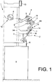
- FIG. 1 one half of an open-end spinning machine known per se is indicated and marked with 1.
- Such spinning machines have a large number of work stations 2, each of which is equipped with a spinning device 3 and a winding device 4.
- sliver 6 is spun into threads 7, which on the Winding devices 4 are wound into cross-wound bobbins 8.
- the winding devices 4 are each equipped with a bobbin frame 9 for rotatably holding a cheese 8 or an empty tube and with a winding drum 11 that can be driven by a single motor for rotating the cheese 8.
- these have for example in the DE 101 39 072 A1 largely self-sufficient workplaces 2 described, each via a single-motor-driven thread traversing device 18, a single-motor-driven thread take-off device 54, a workstation's own
- Suction nozzle 14 a piecing element 20 and a thread storage nozzle 60.
- the open-end spinning machine 1 also has a bobbin transport device 12 for disposing of the cross-wound bobbins 8 completed on the bobbin devices 4.
- a service unit (not shown), for example a so-called changing and cleaning trolley, can also be displaceable on a guide rail 13 and a support rail 15.
- Such service units intervene automatically when a need for action arises at one of the work stations 2.
- Such a need for action exists, for example, when a full cheese is to be exchanged for a new empty tube at one of the work stations 2.
- the Fig. 2 shows in perspective representation and on a larger scale one of the in Fig.1 schematically indicated work station 2 of an open-end rotor spinning machine 1.
- Such jobs 2 have, as above with reference to Fig.1 already explained, including via an open-end spinning device 3 and a winding device 4.
- a piecing element 16 is arranged in the area of the so-called thread take-off tube 21 of the open-end spinning device 3, which takes over the thread 7 retrieved by the suction nozzle 14 from the cheese 8 after a thread breakage and prepares the thread end for re-spinning .
- such workplaces 2 have a thread withdrawal device 54, which both removes the spinning thread 7 from the open-end spinning device 3 during regular spinning operation and ensures a defined return of a prepared thread 7 into the open-end spinning device 3 during re-spinning.
- the winding device 4 has a bobbin frame 9 for rotatably holding the cheese 8, a winding drum 11 that can be acted upon by a reversible individual drive 56, and a thread traversing device 18 that is driven, for example, by means of a stepping motor 57. Furthermore, such self-sufficient work stations 1 each have a pivotably mounted suction nozzle 14, which is adjustable by means of a stepper motor 58 between a thread take-up position located in the area of the winding device 4 and a thread transfer position located in the area of the spinning device 3.
- Each of the work stations 2 also has a thread monitor 26, a waxing device 17 and a thread storage nozzle 60 which can be subjected to a defined negative pressure and which is used on the one hand during the start-up of the work station 2 and on the other hand when creating a thread end reserve 10. That is, the thread storage nozzle 60 stores a thread end reserve 10 of excess thread length both during start-up of the work station 2 and during creation, thereby ensuring that the thread 7 is always wound with a correct winding tension.
- both the thread storage nozzle 60 and the pivotably mounted suction nozzle 14 are connected to a machine's own negative pressure network 19, the negative pressure source of which is identified by the reference number 30.
- the suction nozzle 14 and the thread storage nozzle 60 are connected to the negative pressure network 19 of the textile machine 1, for example each via a connection line 22 or 23.
- a closure means 24 is integrated in the connection line 22 and a closure means 25 is integrated in the connection line 23, the closure means 24 and 25 being connected via control lines 27, 28 to a control device 29 that is preferably internal to the workstation.
- Fig. 3 shows a completed cheese 8, that is, a cheese with a thread end reserve 10, which was created according to the method according to the invention.
- some parallel windings 32 preferably three, are arranged on the coil surface 34.
- thread tendon 31 which can be easily recognized by the operating personnel and which is easy to handle for detaching the thread end reserve 10.
- the bobbin surface 34 is displaced so that a thread tendon 31 is formed, which is then fixed by the parallel windings 32.
- the control device 29 When this thread end reserve 10 is created, the control device 29 simultaneously actuates the closure means 24 in the sense of "opening" and thus connects the thread storage nozzle 60 to the vacuum network 19 of the textile machine 1 via the line 22. The then present at the mouth of the thread storage nozzle 60 acts on the thread 7 running up on the cheese 8 so that any excess thread length that is created is immediately sucked into the thread storage nozzle 60 as a thread loop and the thread is thus kept taut at all times.
Landscapes
- Engineering & Computer Science (AREA)
- Textile Engineering (AREA)
- Mechanical Engineering (AREA)
- Yarns And Mechanical Finishing Of Yarns Or Ropes (AREA)
- Looms (AREA)
- Replacing, Conveying, And Pick-Finding For Filamentary Materials (AREA)
- Winding Filamentary Materials (AREA)
Claims (5)
- Procédé d'actionnement d'un dispositif de bobinage (4) d'une machine textile (1) produisant des bobines croisées et équipée d'un cantre (9) à bobines, conçu pour retenir une bobine croisée (8) avec liberté de rotation ; d'un cylindre (11) d'entraînement de bobines, conçu pour faire tourner ladite bobine croisée (8) et pouvant être sollicité par un entraînement individuel ; ainsi que d'un système (18) de déplacement de fil, pouvant être entraîné par moteur individuel et pouvant être piloté de manière bien définie, sachant que, lors de l'atteinte d'un diamètre de bobine croisée pouvant être préétabli, ou d'une longueur de fil pouvant être préétablie, le guide-fil (40) dudit système (18) de déplacement du fil est positionné à l'extérieur de la zone d'enroulement de la bobine croisée ou à l'intérieur de ladite zone d'enroulement de la bobine croisée, durant un laps de temps réglable, en vue d'instaurer une réserve de fil définitive (10) comprenant des enroulements parallèles,
caractérisé par
la mise en service, au cours de l'instauration de la réserve de fil définitive (10), d'une buse (60) d'accumulation de fil qui peut être sollicitée par une dépression, est spécifiquement affectée à un emplacement de bobine et agit sur le fil (7), parvenant sur la bobine croisée (8), de façon telle qu'une longueur de fil excédentaire, engendrée lors de l'enroulement de ladite réserve de fil définitive (10), soit stockée provisoirement en garantissant, de la sorte, une tension minimale du fil qui est nécessaire pour procurer un blocage à demeure sûr de ladite réserve de fil définitive (10) sur le corps de bobinage, ou sur le bobinot de ladite bobine croisée. - Procédé selon la revendication 1, caractérisé par le fait que, durant l'instauration de la réserve de fil définitive (10), le guide-fil (40) du système (18) de déplacement du fil dépose tout d'abord ledit fil (7) avec dépassement au-delà de l'un des flancs (35) de la bobine croisée (8), puis le retient fermement en des enroulements parallèles (32) sur la surface (34) de ladite bobine croisée (8).
- Procédé selon la revendication 2, caractérisé par le fait que le guide-fil (40) dépose le fil (7) avec court dépassement au-delà du flanc (35) situé à gauche de la bobine croisée (8), en considérant à partir du côté frontal du poste de travail (2).
- Procédé selon l'une des revendications précédentes, caractérisé par le fait que le fil (7) est fermement retenu, sur la surface (34) de la bobine croisée (8), par un nombre d'enroulements parallèles (32) qui est tributaire du diamètre de ladite bobine croisée (8).
- Dispositif de bobinage d'une machine textile (1) produisant des bobines croisées, dédié à la mise en œuvre du procédé conforme à la revendication 1 et équipé d'un cantre (9) à bobines, conçu pour retenir une bobine croisée (8) avec liberté de rotation ; d'un cylindre (11) d'entraînement de bobines, conçu pour faire tourner ladite bobine croisée (8) et pouvant être sollicité par un entraînement individuel ; ainsi que d'un système (18) de déplacement de fil, pouvant être entraîné par moteur individuel et pouvant être piloté de manière bien définie,
caractérisé par le fait
que chacun des nombreux postes de travail (2) de la machine textile (1) est équipé d'une buse (60) d'accumulation de fil qui peut être sollicitée par une dépression, peut être mise en service de façon bien définie, et dont l'embouchure se trouve dans la région du trajet de défilement du fil (7) parvenant sur la bobine croisée (8).
Applications Claiming Priority (1)
| Application Number | Priority Date | Filing Date | Title |
|---|---|---|---|
| DE102007023490A DE102007023490A1 (de) | 2007-05-19 | 2007-05-19 | Verfahren und Vorrichtung zum Betreiben einer Spulvorrichtung einer Kreuzspulen herstellenden Textilmaschine |
Publications (4)
| Publication Number | Publication Date |
|---|---|
| EP1995200A2 EP1995200A2 (fr) | 2008-11-26 |
| EP1995200A3 EP1995200A3 (fr) | 2012-04-04 |
| EP1995200B1 EP1995200B1 (fr) | 2017-05-31 |
| EP1995200B2 true EP1995200B2 (fr) | 2020-09-23 |
Family
ID=39712039
Family Applications (1)
| Application Number | Title | Priority Date | Filing Date |
|---|---|---|---|
| EP08007077.4A Active EP1995200B2 (fr) | 2007-05-19 | 2008-04-10 | Procédé et dispositif de fonctionnement d'un dispositif de bobinage d'une machine textile produisant des bobines croisées |
Country Status (4)
| Country | Link |
|---|---|
| US (1) | US20080283655A1 (fr) |
| EP (1) | EP1995200B2 (fr) |
| CN (1) | CN101306776B (fr) |
| DE (1) | DE102007023490A1 (fr) |
Families Citing this family (10)
| Publication number | Priority date | Publication date | Assignee | Title |
|---|---|---|---|---|
| DE102009009971B4 (de) * | 2009-02-21 | 2017-03-16 | Saurer Germany Gmbh & Co. Kg | Verfahren und Vorrichtung zum Betreiben einer Arbeitsstelle einer Kreuzspulen herstellenden Textilmaschine sowie Arbeitsstelle zur Durchführung des Verfahrens |
| CN102139556B (zh) * | 2010-11-18 | 2012-07-04 | 江苏舒尔雅家纺有限公司 | 平网印花机生产流水线无张力供布装置 |
| CN105600588B (zh) * | 2016-01-13 | 2017-04-26 | 杭州长翼纺织机械有限公司 | 一种自动绕线机 |
| CN105946339B (zh) * | 2016-06-22 | 2018-02-13 | 浙江东山广信数码印花设备有限公司 | 适用于高弹性面料的移动式贴布装置 |
| CZ309324B6 (cs) * | 2016-11-14 | 2022-08-24 | Rieter Cz S.R.O. | Způsob definovaného uložení konce příze na cívce |
| CZ2016708A3 (cs) * | 2016-11-14 | 2018-06-06 | Rieter Cz S.R.O. | Způsob definovaného uložení konce příze na cívce |
| CN111392511B (zh) * | 2020-04-26 | 2024-08-16 | 苏州智殷自动化有限公司 | 用于轮胎钢丝绕线装置的绕线盘自动装卸系统 |
| CN114084715B (zh) * | 2020-05-20 | 2024-02-06 | 台州唯德包装股份有限公司 | 一种pp编织打包带加工收卷装置的收卷方法 |
| DE102020127007A1 (de) * | 2020-10-14 | 2022-04-14 | Saurer Spinning Solutions Gmbh & Co. Kg | Verfahren zum Betreiben einer Spinnmaschine und Spinnmaschine |
| DE102021130062A1 (de) | 2021-11-17 | 2023-05-17 | Maschinenfabrik Rieter Ag | Verfahren zum Betreiben einer Spulstelle einer Spulmaschine sowie Spulmaschine |
Citations (4)
| Publication number | Priority date | Publication date | Assignee | Title |
|---|---|---|---|---|
| DE3734478A1 (de) † | 1987-10-12 | 1989-04-27 | Schubert & Salzer Maschinen | Verfahren und vorrichtung zum fuehren, halten und trennen eines fadens beim spulenwechsel |
| DE10139075A1 (de) † | 2001-08-09 | 2003-02-20 | Schlafhorst & Co W | Offenend-Rotorspinnmaschine |
| DE102005045712A1 (de) † | 2005-09-24 | 2007-03-29 | Saurer Gmbh & Co. Kg | Fadenabzugsrolle für eine Kreuzspulen herstellende Textilmaschine |
| DE102005048041A1 (de) † | 2005-10-07 | 2007-04-12 | Saurer Gmbh & Co. Kg | Fadenabzugseinrichtung für eine Kreuzspulen herstellende Textilmaschine |
Family Cites Families (16)
| Publication number | Priority date | Publication date | Assignee | Title |
|---|---|---|---|---|
| US3842579A (en) * | 1972-04-29 | 1974-10-22 | Skf Kugellagerfabriken Gmbh | Apparatus for temporarily storing thread in a spindleless spinning machine |
| JPS5948228B2 (ja) * | 1976-04-27 | 1984-11-24 | 株式会社豊田自動織機製作所 | トランスフア・テイル巻き付け装置 |
| DE3602574C2 (de) * | 1986-01-29 | 1997-06-12 | Schlafhorst & Co W | Kreuzspulen herstellende Maschine mit Vorrichtung zur Bildung einer Fadenendreserve auf einer fertig gewickelten Spule |
| JPH02239063A (ja) | 1989-03-13 | 1990-09-21 | Murata Mach Ltd | 自動ワインダー |
| JP2751499B2 (ja) * | 1989-12-18 | 1998-05-18 | 村田機械株式会社 | テールエンドの糸処理方法 |
| DE4004028C2 (de) * | 1990-02-10 | 2001-06-07 | Schlafhorst & Co W | Verfahren und Vorrichtung zum Bilden einer Fadenreserve auf einer Kreuzspule |
| DE4023291A1 (de) | 1990-07-21 | 1992-05-14 | Schubert & Salzer Maschinen | Verfahren und vorrichtung zur bildung einer fadenendreservewicklung auf spulen an einer textilmaschine |
| US5393002A (en) * | 1990-07-21 | 1995-02-28 | Schubert & Salzer Maschinenfabrik Ag | Process and device for the constitution of a yarn end reserve winding on yarn packages of a textile machine |
| DE19650879A1 (de) * | 1996-12-07 | 1998-06-10 | Schlafhorst & Co W | Kreuzspulen herstellende Textilmaschine |
| JP3698873B2 (ja) * | 1997-10-03 | 2005-09-21 | ナブテスコ株式会社 | 糸条パッケージの形成方法および形成装置 |
| EP1089933B1 (fr) * | 1998-06-12 | 2003-10-08 | Maschinenfabrik Rieter Ag | Changement de fil |
| DE50003358D1 (de) * | 1999-03-13 | 2003-09-25 | Barmag Barmer Maschf | Vorrichtung und verfahren zum führen und schneiden eines zulaufenden fadens beim spulenwechsel |
| EP1125880A3 (fr) | 2000-02-17 | 2002-08-28 | Schärer Schweiter Mettler AG | Dispositif de production de bobines sur une machine à filer à bout libre |
| EP1125879A3 (fr) | 2000-02-17 | 2002-08-28 | Schärer Schweiter Mettler AG | Dispositif pour la formation d'une réserve de fil et/ou d'un enroulement décalé |
| DE10041973A1 (de) * | 2000-08-25 | 2002-03-07 | Rieter Ingolstadt Spinnerei | Offenend-Spinnvorrichtung sowie Verfahren zur vorübergehenden Aufnahme eines Fadens mit Hilfe einer derartigen Offenend-Spinnvorrichtung |
| DE10139072B4 (de) | 2001-08-09 | 2009-12-17 | Oerlikon Textile Gmbh & Co. Kg | Serviceaggregat zum Wiederanspinnen von Arbeitsstellen einer Offenend-Spinnmaschine |
-
2007
- 2007-05-19 DE DE102007023490A patent/DE102007023490A1/de not_active Withdrawn
-
2008
- 2008-04-10 EP EP08007077.4A patent/EP1995200B2/fr active Active
- 2008-05-06 US US12/151,310 patent/US20080283655A1/en not_active Abandoned
- 2008-05-07 CN CN2008100928749A patent/CN101306776B/zh active Active
Patent Citations (4)
| Publication number | Priority date | Publication date | Assignee | Title |
|---|---|---|---|---|
| DE3734478A1 (de) † | 1987-10-12 | 1989-04-27 | Schubert & Salzer Maschinen | Verfahren und vorrichtung zum fuehren, halten und trennen eines fadens beim spulenwechsel |
| DE10139075A1 (de) † | 2001-08-09 | 2003-02-20 | Schlafhorst & Co W | Offenend-Rotorspinnmaschine |
| DE102005045712A1 (de) † | 2005-09-24 | 2007-03-29 | Saurer Gmbh & Co. Kg | Fadenabzugsrolle für eine Kreuzspulen herstellende Textilmaschine |
| DE102005048041A1 (de) † | 2005-10-07 | 2007-04-12 | Saurer Gmbh & Co. Kg | Fadenabzugseinrichtung für eine Kreuzspulen herstellende Textilmaschine |
Also Published As
| Publication number | Publication date |
|---|---|
| US20080283655A1 (en) | 2008-11-20 |
| EP1995200B1 (fr) | 2017-05-31 |
| EP1995200A2 (fr) | 2008-11-26 |
| CN101306776B (zh) | 2012-11-14 |
| EP1995200A3 (fr) | 2012-04-04 |
| DE102007023490A1 (de) | 2008-11-20 |
| CN101306776A (zh) | 2008-11-19 |
Similar Documents
| Publication | Publication Date | Title |
|---|---|---|
| EP1995200B2 (fr) | Procédé et dispositif de fonctionnement d'un dispositif de bobinage d'une machine textile produisant des bobines croisées | |
| EP1428783B1 (fr) | Méthode et dispositif de mise en service d'un poste de travail d'une machine textile pour la fabrication de bobines à spires croisées | |
| DE102007053467B4 (de) | Verfahren und Vorrichtung zum Betreiben einer Offenend-Rotorspinnmaschine | |
| DE10139074B4 (de) | Offenend-Rotorspinnmaschine | |
| DE102007056561A1 (de) | Kreuzspulen herstellende Textilmaschine | |
| DE102009024037A1 (de) | Verfahren zur Behebung einer Fadenunterbrechung an einer Arbeitsstelle einer Spulmaschine und Arbeitsstelle einer Spulmaschine | |
| DE102011101629A1 (de) | Fadenspleißvorrichtung für eine Arbeitsstelle einer Kreuzspulen herstellenden Textilmaschine | |
| DE102008026777A1 (de) | Saugdüse | |
| DE102009009971A1 (de) | Verfahren und Vorrichtung zum Betreiben einer Arbeitsstelle einer Kreuzspulen herstellenden Textilmaschine sowie Arbeitsstelle zur Durchführung des Verfahrens | |
| DE10139072A1 (de) | Serviceaggregat zum Wiederanspinnen von Arbeitsstellen einer Offenend-Spinnmaschine | |
| DE102012016853A1 (de) | Verfahren zum Verbinden eines Ober- und Unterfadens an einer Arbeitsstelle einer Spulmaschine und Arbeitsstelle einer Spulmaschine | |
| EP2388222B1 (fr) | Procédé de fabrication de cannettes de filature | |
| DE102016119542A1 (de) | Fadenspleißvorrichtung für eine Arbeitsstelle einer Kreuzspulen herstellenden Textilmaschine | |
| DE102005045842A1 (de) | Verfahren zum Einfädeln eines Fadens | |
| DE102006050220B4 (de) | Verfahren und Vorrichtung zum Betreiben einer Kreuzspulen herstellenden Textilmaschine | |
| EP1828040B1 (fr) | Poste de travail de bobineuse | |
| EP2279976B1 (fr) | Procédé destiné au fonctionnement de postes de travail d'une machine textile produisant des bobines croisées | |
| DE2543986A1 (de) | Verfahren und vorrichtung zur sicherung einer reservewicklung auf einer spulenhuelse | |
| EP0979791A2 (fr) | Machine textile fabricant des bobines croisées | |
| EP1076028A2 (fr) | Dispositif de rattachement du fil pour une machine textile fabriquant des bobines à spires croisées | |
| EP1127831B1 (fr) | Dispositif de mise en service d'un poste de travail d'une machine textile pour la fabrication de bobines à spires croisées | |
| DE102018120457A1 (de) | Fadenspleißvorrichtung für eine Arbeitsstelle einer Kreuzspulen herstellenden Textilmaschine | |
| DE102007056563B4 (de) | Hülsenspeicher für eine nicht mit einem selbsttätig arbeitenden Anspinnaggregat ausgestattete Offenend-Rotorspinnmaschine | |
| EP2500452B1 (fr) | Poste de travail pour métier à tisser à rotor à extrémité ouverte | |
| DE102004057825A1 (de) | Spulstelle einer Kreuzspule herstellenden Textilmaschine |
Legal Events
| Date | Code | Title | Description |
|---|---|---|---|
| PUAI | Public reference made under article 153(3) epc to a published international application that has entered the european phase |
Free format text: ORIGINAL CODE: 0009012 |
|
| AK | Designated contracting states |
Kind code of ref document: A2 Designated state(s): AT BE BG CH CY CZ DE DK EE ES FI FR GB GR HR HU IE IS IT LI LT LU LV MC MT NL NO PL PT RO SE SI SK TR |
|
| AX | Request for extension of the european patent |
Extension state: AL BA MK RS |
|
| PUAL | Search report despatched |
Free format text: ORIGINAL CODE: 0009013 |
|
| AK | Designated contracting states |
Kind code of ref document: A3 Designated state(s): AT BE BG CH CY CZ DE DK EE ES FI FR GB GR HR HU IE IS IT LI LT LU LV MC MT NL NO PL PT RO SE SI SK TR |
|
| AX | Request for extension of the european patent |
Extension state: AL BA MK RS |
|
| RIC1 | Information provided on ipc code assigned before grant |
Ipc: B65H 59/10 20060101ALI20120224BHEP Ipc: B65H 54/34 20060101AFI20120224BHEP Ipc: D01H 1/38 20060101ALI20120224BHEP |
|
| 17P | Request for examination filed |
Effective date: 20121004 |
|
| AKX | Designation fees paid |
Designated state(s): CZ DE IT TR |
|
| RAP1 | Party data changed (applicant data changed or rights of an application transferred) |
Owner name: SAURER GERMANY GMBH & CO. KG |
|
| 17Q | First examination report despatched |
Effective date: 20160121 |
|
| GRAP | Despatch of communication of intention to grant a patent |
Free format text: ORIGINAL CODE: EPIDOSNIGR1 |
|
| INTG | Intention to grant announced |
Effective date: 20161220 |
|
| GRAS | Grant fee paid |
Free format text: ORIGINAL CODE: EPIDOSNIGR3 |
|
| GRAA | (expected) grant |
Free format text: ORIGINAL CODE: 0009210 |
|
| AK | Designated contracting states |
Kind code of ref document: B1 Designated state(s): CZ DE IT TR |
|
| REG | Reference to a national code |
Ref country code: DE Ref legal event code: R096 Ref document number: 502008015337 Country of ref document: DE |
|
| REG | Reference to a national code |
Ref country code: DE Ref legal event code: R026 Ref document number: 502008015337 Country of ref document: DE |
|
| PLBI | Opposition filed |
Free format text: ORIGINAL CODE: 0009260 |
|
| PLAX | Notice of opposition and request to file observation + time limit sent |
Free format text: ORIGINAL CODE: EPIDOSNOBS2 |
|
| 26 | Opposition filed |
Opponent name: MASCHINENFABRIK RIETER AG Effective date: 20180227 |
|
| PLBB | Reply of patent proprietor to notice(s) of opposition received |
Free format text: ORIGINAL CODE: EPIDOSNOBS3 |
|
| REG | Reference to a national code |
Ref country code: DE Ref legal event code: R081 Ref document number: 502008015337 Country of ref document: DE Owner name: SAURER SPINNING SOLUTIONS GMBH & CO. KG, DE Free format text: FORMER OWNER: SAURER GERMANY GMBH & CO. KG, 42897 REMSCHEID, DE |
|
| RAP2 | Party data changed (patent owner data changed or rights of a patent transferred) |
Owner name: SAURER SPINNING SOLUTIONS GMBH & CO. KG |
|
| PGFP | Annual fee paid to national office [announced via postgrant information from national office to epo] |
Ref country code: CZ Payment date: 20190328 Year of fee payment: 12 |
|
| PGFP | Annual fee paid to national office [announced via postgrant information from national office to epo] |
Ref country code: DE Payment date: 20190502 Year of fee payment: 12 |
|
| PLBP | Opposition withdrawn |
Free format text: ORIGINAL CODE: 0009264 |
|
| PUAH | Patent maintained in amended form |
Free format text: ORIGINAL CODE: 0009272 |
|
| STAA | Information on the status of an ep patent application or granted ep patent |
Free format text: STATUS: PATENT MAINTAINED AS AMENDED |
|
| 27A | Patent maintained in amended form |
Effective date: 20200923 |
|
| AK | Designated contracting states |
Kind code of ref document: B2 Designated state(s): CZ DE IT TR |
|
| REG | Reference to a national code |
Ref country code: DE Ref legal event code: R102 Ref document number: 502008015337 Country of ref document: DE |
|
| PG25 | Lapsed in a contracting state [announced via postgrant information from national office to epo] |
Ref country code: CZ Free format text: LAPSE BECAUSE OF NON-PAYMENT OF DUE FEES Effective date: 20200410 |
|
| REG | Reference to a national code |
Ref country code: DE Ref legal event code: R119 Ref document number: 502008015337 Country of ref document: DE |
|
| PG25 | Lapsed in a contracting state [announced via postgrant information from national office to epo] |
Ref country code: DE Free format text: LAPSE BECAUSE OF NON-PAYMENT OF DUE FEES Effective date: 20201103 |
|
| PGFP | Annual fee paid to national office [announced via postgrant information from national office to epo] |
Ref country code: TR Payment date: 20220407 Year of fee payment: 15 |
|
| PGFP | Annual fee paid to national office [announced via postgrant information from national office to epo] |
Ref country code: IT Payment date: 20240430 Year of fee payment: 17 |