EP1995006B1 - Procédé pour le refroidissement rapide d'une presse isostatique á chaud et presse isostatique á chaud - Google Patents
Procédé pour le refroidissement rapide d'une presse isostatique á chaud et presse isostatique á chaud Download PDFInfo
- Publication number
- EP1995006B1 EP1995006B1 EP08008674.7A EP08008674A EP1995006B1 EP 1995006 B1 EP1995006 B1 EP 1995006B1 EP 08008674 A EP08008674 A EP 08008674A EP 1995006 B1 EP1995006 B1 EP 1995006B1
- Authority
- EP
- European Patent Office
- Prior art keywords
- fluid
- space
- load
- nozzle
- hot isostatic
- Prior art date
- Legal status (The legal status is an assumption and is not a legal conclusion. Google has not performed a legal analysis and makes no representation as to the accuracy of the status listed.)
- Active
Links
Images


Classifications
-
- B—PERFORMING OPERATIONS; TRANSPORTING
- B22—CASTING; POWDER METALLURGY
- B22F—WORKING METALLIC POWDER; MANUFACTURE OF ARTICLES FROM METALLIC POWDER; MAKING METALLIC POWDER; APPARATUS OR DEVICES SPECIALLY ADAPTED FOR METALLIC POWDER
- B22F3/00—Manufacture of workpieces or articles from metallic powder characterised by the manner of compacting or sintering; Apparatus specially adapted therefor ; Presses and furnaces
- B22F3/12—Both compacting and sintering
- B22F3/14—Both compacting and sintering simultaneously
- B22F3/15—Hot isostatic pressing
-
- B—PERFORMING OPERATIONS; TRANSPORTING
- B30—PRESSES
- B30B—PRESSES IN GENERAL
- B30B11/00—Presses specially adapted for forming shaped articles from material in particulate or plastic state, e.g. briquetting presses, tabletting presses
- B30B11/001—Presses specially adapted for forming shaped articles from material in particulate or plastic state, e.g. briquetting presses, tabletting presses using a flexible element, e.g. diaphragm, urged by fluid pressure; Isostatic presses
- B30B11/002—Isostatic press chambers; Press stands therefor
-
- B—PERFORMING OPERATIONS; TRANSPORTING
- B22—CASTING; POWDER METALLURGY
- B22F—WORKING METALLIC POWDER; MANUFACTURE OF ARTICLES FROM METALLIC POWDER; MAKING METALLIC POWDER; APPARATUS OR DEVICES SPECIALLY ADAPTED FOR METALLIC POWDER
- B22F3/00—Manufacture of workpieces or articles from metallic powder characterised by the manner of compacting or sintering; Apparatus specially adapted therefor ; Presses and furnaces
- B22F3/12—Both compacting and sintering
- B22F3/14—Both compacting and sintering simultaneously
- B22F3/15—Hot isostatic pressing
- B22F2003/153—Hot isostatic pressing apparatus specific to HIP
-
- F—MECHANICAL ENGINEERING; LIGHTING; HEATING; WEAPONS; BLASTING
- F28—HEAT EXCHANGE IN GENERAL
- F28C—HEAT-EXCHANGE APPARATUS, NOT PROVIDED FOR IN ANOTHER SUBCLASS, IN WHICH THE HEAT-EXCHANGE MEDIA COME INTO DIRECT CONTACT WITHOUT CHEMICAL INTERACTION
- F28C3/00—Other direct-contact heat-exchange apparatus
- F28C3/02—Other direct-contact heat-exchange apparatus the heat-exchange media both being gases or vapours
-
- F—MECHANICAL ENGINEERING; LIGHTING; HEATING; WEAPONS; BLASTING
- F28—HEAT EXCHANGE IN GENERAL
- F28F—DETAILS OF HEAT-EXCHANGE AND HEAT-TRANSFER APPARATUS, OF GENERAL APPLICATION
- F28F13/00—Arrangements for modifying heat-transfer, e.g. increasing, decreasing
- F28F13/02—Arrangements for modifying heat-transfer, e.g. increasing, decreasing by influencing fluid boundary
Definitions
- the invention relates to a method for rapid cooling of a hot isostatic press according to the preamble of claim 1 and a hot isostatic press according to the preamble of claim 13.
- Hot isostatic presses or autoclave ovens are used today for a variety of applications.
- solid workpieces or molding compounds consisting of powder are compacted in a die under high pressure and high temperature. In this case, similar but also different materials can be interconnected.
- the workpieces are placed in an oven with a heater, which in turn is surrounded by a high pressure vessel.
- a complete isostatic pressing is performed by the all-round pressure of a fluid or inert gas, usually argon, until the workpieces are optimally compressed.
- This process is also used to re-densify components, for example, ceramic ones Materials, eg for hip joint prostheses, for aluminum cast components in automotive or engine construction, as cylinder heads of car engines, or precision castings made of titanium alloys, such as turbine blades to effect.
- components for example, ceramic ones Materials, eg for hip joint prostheses, for aluminum cast components in automotive or engine construction, as cylinder heads of car engines, or precision castings made of titanium alloys, such as turbine blades to effect.
- the pores formed in the previous manufacturing process are closed, existing imperfections are connected and the microstructural properties are improved.
- Another area of application is the production of powdered components close to the final contours, which are compacted and sintered during the process.
- HIP cycles usually take a long time, from several hours to several days. A significant part of the cycle costs are caused by the machine hourly rate due to the capital tie-up.
- the relatively long cooling times from operating temperature to a permissible temperature at which the press installation can be opened without risk usually make up more than one third of the cycle time and are not of any use in terms of process technology.
- the cooling also plays an essential role for the material properties of the parts to be produced. Many materials require compliance with a certain maximum cooling rate for reasons of material quality.
- Autoclaves with hot gas circulation with or without mechanical aids, such as blowers, are sufficiently known from the prior art.
- mechanical aids such as blowers
- the natural convection and the redistribution of the gas in the autoclave are used by existing or promoted temperature differences (heating or cooling on external walls). It drops colder fluid down and hotter fluid rises.
- vanes Through the use of vanes, such fluid flows can be used in a controlled manner to provide uniform heating or cooling recirculation in the autoclave.
- guide or convection sleeves which consist of a pipe open at the top and bottom. When heated, heat sources in the oven provide power and the flow will commence depending on the location of the heat source.
- the cooling fluid between the convection sleeve and the cooling outer wall falls down, pushing the warmer fluid inside the sleeve past the workpieces upwards.
- the incoming flow from below pushes the fluid towards the outside and thus drops the fluid between the outer wall and the sleeve back down. This again creates a corresponding cooling whereby the continuous cooling process is maintained.
- An embodiment for the rapid cooling of a HIP system is, for example, with the DE 38 33 337 A1 known.
- a gas circulation between the hot space inside the insulating hood and the cold room outside the insulating produced by valves in the bottom space of the circuit is opened.
- In the upper lid of the insulating constantly open holes are available through which the hot fluid can escape.
- a disadvantage of this embodiment is that very cold fluid from below flows back into the hot room and comes directly into contact with the loading of the furnace or the workpieces. The hot room is thus filled from bottom to top with cold gas. This has the disadvantage that on the one hand a sudden cooling can occur with too uncertain einberichtbaren parameters and that no uniform cooling rate over the entire batch space is achieved.
- the problems described above, such as distortion, cracks or destruction can occur due to the uneven cooling.
- Another embodiment for the rapid cooling of a HIP system is also with the EP 1 009 563 B1 known.
- the object of the present invention is now to provide a method for rapid cooling of a hot isostatic press and to provide a hot isostatic press suitable for carrying out the method, which allow uniform cooling of the loading space or the loading, with a colder fluid brisk with hot fluid in the Loading space of the hot isostatic press is mixed and at the same time a sufficiently fast and above all ensured circulation of the fluid in the entire pressure vessel, but especially in the loading space is achieved in order to achieve a uniform cooling of the entire load.
- the solution of the task for the method according to claim 1 is that in the interior of the loading space of a pressure vessel to form a rotational flow via at least one nozzle fluid is injected, wherein the fluid mixes with fluid from the vicinity of the load during the passage of the rotary flow in the vicinity of the insulation, and wherein the fluid leaving the nozzle has a lower temperature than the fluid in the loading space and / or the loading.
- the solution to the problem for the hot isostatic press for carrying out the method according to claim 13 is that within the pressure vessel at least one line is arranged with connection to at least one nozzle in the interior of the loading space, wherein the conduit with fluid at a lower temperature than the fluid in the loading space and / or the load is supplied.
- the teaching of the invention is that a rotational flow within the loading space is formed by the targeted injection of cool fluid in the upper region of the pressure vessel. Due to the injection at high speed at the upper end of the loading space creates a cyclone effect within the loading space, that is, cooler fluid from the The nozzle is moved in a circle along the insulation by the rotation and sinks downwards due to the higher fluid density. Lack of separation from the loading space causes mixing between the hot fluid near the load and the cyclonic cold fluid. The case falling down fluid hereby pulls hot fluid from the inner region of the loading space with it creating a mixing temperature. Due to the optimal mixing and ensured for physical reasons securing the load from too cold fluid an optimal and uniform cooling gradient of the individual loading parts is ensured.
- the rotational movement of the fluid in the interior of the loading space also ensures that rising and falling fluid no temperature niches in the loading space due to undercuts of the load or a load carrier can arise. Niches with normally stagnant fluid are due to the rotating fluid and the resulting additional turbulence on, for example, undercuts still sufficiently mixed to compensate for temperature differences perfectly.
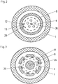
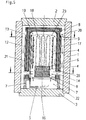
- the pressure vessel 1 shown in the figures has a loading area 19, which is usually located on the inside, and an insulation 8 arranged therebetween. Within the insulation 8 heating elements 4 are arranged and a load 18 is usually placed on a load carrier plate 6 or by means of a load carrier (not shown) on the Loading carrier plate 6 is provided.
- the pressure vessel 1 has the rest of the closure lid 2 and 3 for loading and unloading of the pressure vessel 1 are used, but which are further considered to simplify the description of the pressure vessel 1 as belonging.
- at least one nozzle 13 is arranged in the loading space 19 through which fluid 23, preferably at high speed, is flowed through to form a rotational flow 23.
- the fluid has a lower temperature than the fluid in the loading space 19 and / or the load 18 itself and is forced by rotation to the inner wall of the insulation 8 due to physical laws.
- the outside rotating fluid mixes with warmer fluid from the vicinity of the load 18.
- the highest fluid Temperature In a vertical section to the central axis 26 of the pressure vessel 1 is thus found in the vicinity of the central axis 26, the highest fluid Temperature.
- the temperature decreases during a current rotational flow 23 continuously in the direction of insulation 8 from.
- the fluid is expelled horizontally to the central axis 26 of the pressure vessel 1 from the nozzle 13.
- Optimal is also a tangential Ausdüsung of the fluid to the central axis 26 of the pressure vessel 1.
- the cooled fluid returned to the pressure vessel 1 via the inlet 25 is fed into the line 12 via an ejector pump, comprising a sparger 15 and a venturi 16, with the admixing of fluid from the floor space 22 ( FIG. 1 ).
- an ejector pump comprising a sparger 15 and a venturi 16, with the admixing of fluid from the floor space 22 ( FIG. 1 ).
- the fluid from the perforations 7 can enter directly into the bottom space 22 from the loading space 19 and / or from the second annular gap 17. This is a structural design and is defined by the cooling rates to be achieved, because the fluid from the loading space 19 is significantly warmer than from the second annular gap 17.
- an outer circulation circuit 20 is established by means of natural convection in two mutually parallel annular gaps 9, 17, wherein the circulation circuit 20 is disposed completely outside the insulation 8.
- the fluid of the outer circulation circuit 20 and the rotating fluid from the loading chamber 19 can exchange and mix with each other below the loading space by means of openings 14 in the insulation 8.
- Hot gas from the rotary flow 23 can in this case pass through the openings 14 in the outer circulation circuit 20, where it is first mixed with the outer circulation flow and is further cooled by the circulation of the pressure vessel wall 1 and can flow as cooled gas through the openings 14 back below the loading space 19.
- the fluid is injected via the nozzle 13 in or above a guide device 27 in the loading space 19.
- This guide device 27 can be used as a simple or double horizontally arranged disc ( FIG. 4a ) or ring ( FIG. 4b ), which ensures that the cooler fluid exiting from the nozzle 13 before entering the rotational flow 23 to the outer edge of the loading space 19, here formed by the insulation 8, passes. This avoids an uncontrolled flow of cooler fluid into the middle of the loading space 19.
- the guide device 27 may additionally as a horizontally arranged double sheet or double ring, as after the execution in FIG. 4a . b be executed, wherein by the inflow of the cooler fluid from the nozzle 13 can be achieved between the two sheets an optimal and narrow gas flow regardless of the design and height of the upper portion of the insulation 8 (roof).
- the guide device 27 could have the features of the nozzle 13 with respect to the orientation.
- additional perforations 7 may be provided between the outer annular gap 17 and the bottom space 22, as a result of which the fluid cooled at the pressure vessel wall can flow directly back into the floor space 22 (FIG. FIG. 5 ).
Landscapes
- Engineering & Computer Science (AREA)
- Mechanical Engineering (AREA)
- Physics & Mathematics (AREA)
- Fluid Mechanics (AREA)
- Manufacturing & Machinery (AREA)
- Press Drives And Press Lines (AREA)
Claims (24)
- Procédé de refroidissement rapide d'une presse isostatique à chaud, se composant d'un récipient sous pression (1) avec un espace de charge (19) à l'intérieur et une isolation (8) disposée entre, dans lequel des éléments chauffants (4) et une charge (18) sur une plaque porteuse de charge (6) sont disposés à l'intérieur de l'isolation (8),
caractérisé en ce
qu'à l'intérieur et dans la partie supérieure de l'espace de charge (19) d'un récipient sous pression (1), du fluide est injecté par au moins une buse (13) pour former un écoulement rotationnel (23),
dans lequel le fluide, pendant la traversée de l'écoulement rotationnel (23) à proximité de l'isolation (8), se mélange au fluide venant près de la charge (18) et
dans lequel le fluide sortant de la buse (13) présente une température inférieure au fluide dans l'espace de charge (19) et/ou la charge (18). - Procédé selon la revendication 1, caractérisé en ce que le fluide plus froid est injecté de la buse (13) dans l'espace de charge (19), de manière tangentielle à l'axe médian (26) du récipient sous pression (1).
- Procédé selon la revendication 1, caractérisé en ce que le fluide plus froid est injecté de la buse (13) dans l'espace de charge (19), de manière tangentielle, vers le bas ou vers le haut dans un angle légèrement incliné par rapport à l'horizontale.
- Procédé selon la revendication 1, caractérisé en ce que le fluide plus froid est injecté de la buse (13) dans l'espace de charge (19) à une vitesse supérieure.
- Procédé selon la revendication 1, caractérisé en ce que le fluide sortant de la buse (13) est alimenté directement de l'espace de fond (22) dans la ligne (12) à une température plus basse.
- Procédé selon la revendication 1, caractérisé en ce que du fluide est dirigé par une sortie (24) vers un refroidisseur de fluide (10) en-dehors du récipient sous pression (1) et alimenté ensuite dans la ligne (12) par une admission (25).
- Procédé selon la revendication 1, caractérisé en ce que dans l'espace de fond (22), le fluide refroidi en-dehors du récipient sous pression (1) est alimenté par une pompe à jet aspirant, se composant d'un tube de soufflage (15) et d'une buse à effet venturi (16), directement et/ou en mélangeant du fluide, de l'espace de fond (22) à la ligne (12).
- Procédé selon la revendication 1, caractérisé en ce que pour optimiser encore le refroidissement rapide, un circuit de circulation extérieur (20) est établi par convection naturelle (dans deux fentes annulaires (9, 17)) disposées parallèles entre elles), qui est disposé complètement en-dehors de l'isolation (8).
- Procédé selon la revendication 1, caractérisé en ce que le fluide de l'écoulement rotationnel (23) hors de l'espace de charge (19), en-dessous de l'espace de charge (19), pénètre dans le circuit de circulation extérieur (20) par des percées (14) dans l'isolation (8) et se mélange au fluide du circuit de circulation extérieur (20), passe en outre, du fait de la circulation, devant la paroi du récipient sous pression (1) et revient en tant que fluide plus froid par les percées (14) en-dessous de l'espace de charge (19) .
- Procédé selon la revendication 1, caractérisé en ce que du fluide peut pénétrer dans l'espace de fond (22) soit par des percées (7) verticales hors de l'espace de charge (19) et/ou soit par des percées (7) horizontales.
- Procédé selon la revendication 1, caractérisé en ce que le fluide plus froid sortant de la buse (13) est injecté dans un dispositif directionnel (27) avant de pénétrer dans l'espace de charge (19), dans lequel le dispositif directionnel (27) restitue le liquide plus froid sur l'espace de charge (19) dans la partie extérieure à proximité de la paroi de l'isolation (8).
- Procédé selon la revendication 1, caractérisé en ce que le fluide plus froid sortant de la buse (13) est injecté dans un dispositif directionnel (27) avant de pénétrer dans l'espace de charge (19), dans lequel un premier écoulement rotationnel est produit dans le dispositif directionnel (27) avant que le dispositif directionnel (27) ne restitue le liquide plus froid sur l'espace de charge (19) dans la partie extérieure à proximité de la paroi de l'isolation (8).
- Presse isostatique à chaud, se composant d'un récipient sous pression (1) avec un espace de charge (19) à l'intérieur et une isolation (8) disposée entre, dans lequel des éléments chauffants (4) et une charge (18) sur une plaque porteuse de charge (6) sont disposés à l'intérieur de l'isolation (8), pour réaliser le procédé selon la revendication 1, caractérisée en ce que
qu'à l'intérieur du récipient sous pression (1), au moins une ligne (12) reliée à au moins une buse (13) est disposée à l'intérieur et dans la partie supérieure de l'espace de charge (19), dans lequel la ligne (12) est alimentée avec du fluide présentant une température inférieure au fluide dans l'espace de charge (19) et/ou la charge (18). - Presse isostatique à chaud selon la revendication 13, caractérisée en ce que le sens de courant sortant de la buse (13) est disposé horizontal et/ou tangentiel à l'axe médian (26) du récipient sous pression (1).
- Presse isostatique à chaud selon la revendication 13 et/ou 14, caractérisée en ce que le sens de courant sortant de la buse (13) est disposé tangentiel à l'axe médian (26) et est disposé incliné vers le bas ou vers le haut depuis l'horizontale.
- Presse isostatique à chaud selon une ou plusieurs des revendications précédentes 13 à 15, caractérisée en ce que la ligne (12) conduit dans et/ou à travers l'espace de fond (22).
- Presse isostatique à chaud selon une ou plusieurs des revendications précédentes 13 à 16, caractérisée en ce qu'un dispositif de recirculation (5) pour alimenter la ligne (12) en fluide hors de l'espace de fond (22) est disposé dans l'espace de fond (22).
- Presse isostatique à chaud selon une ou plusieurs des revendications précédentes 13 à 17, caractérisée en ce qu'une admission (25) pour amener du fluide refroidi est disposée dans l'espace de fond (22).
- Presse isostatique à chaud selon une ou plusieurs des revendications précédentes 13 à 18, caractérisée en ce qu'une sortie (24) est disposée dans l'espace de fond (22), laquelle est reliée à un refroidisseur de fluide (10) et/ou à un compresseur (11) hors du récipient sous pression (1) et ensuite à l'admission (25).
- Presse isostatique à chaud selon une ou plusieurs des revendications précédentes 13 à 19, caractérisée en ce qu'une pompe à jet aspirant, se composant d'un tube de soufflage (15) et d'une buse à effet venturi (16), est disposée dans l'espace de fond (22), dans laquelle le tube de soufflage est relié à l'admission (25).
- Presse isostatique à chaud selon une ou plusieurs des revendications précédentes 13 à 20, caractérisée en ce que l'isolation (8) présente à l'extérieur une tôle conductrice (21) percée en haut et en bas pour former une fente annulaire (9).
- Presse isostatique à chaud selon une ou plusieurs des revendications précédentes 13 à 21, caractérisée en ce que des percées (14) sont disposées dans l'isolation (8) entre l'espace de charge (19) et l'espace de fond (22) .
- Presse isostatique à chaud selon une ou plusieurs des revendications précédentes 13 à 22, caractérisée en ce que des percées (7) sont disposées entre l'espace de charge (19) et/ou l'espace annulaire (17) et l'espace de fond (22).
- Presse isostatique à chaud selon une ou plusieurs des revendications précédentes 13 à 23, caractérisée en ce qu'un dispositif directionnel (27) dans une tôle au moins horizontale est disposé entre l'espace de charge (19) et la buse (13).
Applications Claiming Priority (1)
| Application Number | Priority Date | Filing Date | Title |
|---|---|---|---|
| DE102007023699.0A DE102007023699B4 (de) | 2007-05-22 | 2007-05-22 | Heiß Isostatische Presse und Verfahren zur Schnellkühlung einer Heiß Isostatischen Presse |
Publications (3)
| Publication Number | Publication Date |
|---|---|
| EP1995006A2 EP1995006A2 (fr) | 2008-11-26 |
| EP1995006A3 EP1995006A3 (fr) | 2009-09-30 |
| EP1995006B1 true EP1995006B1 (fr) | 2018-11-07 |
Family
ID=39735357
Family Applications (1)
| Application Number | Title | Priority Date | Filing Date |
|---|---|---|---|
| EP08008674.7A Active EP1995006B1 (fr) | 2007-05-22 | 2008-05-08 | Procédé pour le refroidissement rapide d'une presse isostatique á chaud et presse isostatique á chaud |
Country Status (6)
| Country | Link |
|---|---|
| US (1) | US8695494B2 (fr) |
| EP (1) | EP1995006B1 (fr) |
| JP (1) | JP5505949B2 (fr) |
| CN (1) | CN101347837B (fr) |
| DE (1) | DE102007023699B4 (fr) |
| ES (1) | ES2709207T3 (fr) |
Families Citing this family (12)
| Publication number | Priority date | Publication date | Assignee | Title |
|---|---|---|---|---|
| DE102007023699B4 (de) | 2007-05-22 | 2020-03-26 | Cremer Thermoprozeßanlagen-GmbH | Heiß Isostatische Presse und Verfahren zur Schnellkühlung einer Heiß Isostatischen Presse |
| DE102008058330A1 (de) * | 2008-11-23 | 2010-05-27 | Dieffenbacher Gmbh + Co. Kg | Verfahren zur Temperierung einer Heiß isostatischen Presse und eine Heiß isostatische Presse |
| DE102008058329A1 (de) * | 2008-11-23 | 2010-05-27 | Dieffenbacher Gmbh + Co. Kg | Verfahren zur Temperierung einer Heiß Isostatischen Presse und eine Heiß Isostatische Presse |
| CN102476445A (zh) * | 2010-11-24 | 2012-05-30 | 浙江中能防腐设备有限公司 | 聚四氟乙烯或改性聚四氟乙烯烧结的热静压设备 |
| US9651309B2 (en) | 2011-01-03 | 2017-05-16 | Quintus Technologies Ab | Pressing arrangement |
| JP5826102B2 (ja) * | 2011-09-21 | 2015-12-02 | 株式会社神戸製鋼所 | 熱間等方圧加圧装置 |
| US9551530B2 (en) * | 2013-03-13 | 2017-01-24 | Quintus Technologies Ab | Combined fan and ejector cooling |
| JP5894967B2 (ja) * | 2013-05-28 | 2016-03-30 | 株式会社神戸製鋼所 | 熱間等方圧加圧装置 |
| JP5931014B2 (ja) * | 2013-07-12 | 2016-06-08 | 株式会社神戸製鋼所 | 熱間等方圧加圧装置 |
| JP6757286B2 (ja) * | 2017-04-07 | 2020-09-16 | 株式会社神戸製鋼所 | 熱間等方圧加圧装置 |
| JP7131932B2 (ja) * | 2018-03-15 | 2022-09-06 | トヨタ自動車株式会社 | アルミニウム合金部材の製造方法 |
| EP3914442B1 (fr) * | 2019-01-25 | 2024-10-23 | Quintus Technologies AB | Procédé dans un arrangement de pressage |
Family Cites Families (15)
| Publication number | Priority date | Publication date | Assignee | Title |
|---|---|---|---|---|
| US2493246A (en) | 1945-02-05 | 1950-01-03 | Wild Barfield Electr Furnaces | Furnace |
| US4867918A (en) * | 1987-12-30 | 1989-09-19 | Union Carbide Corporation | Gas dispersion process and system |
| DE3833337A1 (de) * | 1988-09-30 | 1990-04-05 | Dieffenbacher Gmbh Maschf | Vorrichtung zur schnellkuehlung von werkstuecken und des druckbehaelters in einer hip-anlage |
| SE467611B (sv) * | 1989-04-04 | 1992-08-17 | Asea Brown Boveri | Anordning foer kylning av lasten i en varmisostatpress |
| JPH02302587A (ja) | 1989-05-17 | 1990-12-14 | Nippon Steel Corp | 熱間静水圧加圧装置の冷却装置 |
| US7273749B1 (en) * | 1990-06-04 | 2007-09-25 | University Of Utah Research Foundation | Container for carrying out and monitoring biological processes |
| US5290189A (en) | 1993-08-26 | 1994-03-01 | Gas Research Institute | High temperature industrial heat treat furnace |
| SE507179C2 (sv) * | 1995-12-01 | 1998-04-20 | Asea Brown Boveri | Sätt och anordning för gasrening vid varmisostatisk pressning |
| SE509518C2 (sv) * | 1997-06-13 | 1999-02-08 | Asea Brown Boveri | Anordning för varmisostatisk pressning |
| SE513640C2 (sv) | 1998-09-17 | 2000-10-16 | Flow Holdings Gmbh Sagl Llc | Anordning, användning och förfarande för snabbkylning vid varmisostatisk pressning |
| SE521206C2 (sv) * | 2002-02-20 | 2003-10-14 | Flow Holdings Sagl | Förfarande för kylning av en ugnskammare för varmisostatisk pressning och en anordning härför |
| JP3916490B2 (ja) | 2002-03-28 | 2007-05-16 | 株式会社神戸製鋼所 | 熱間等方圧プレス装置および熱間等方圧プレス方法 |
| JP3836765B2 (ja) | 2002-08-02 | 2006-10-25 | 株式会社神戸製鋼所 | 高圧処理装置 |
| JP4280981B2 (ja) | 2003-06-27 | 2009-06-17 | 株式会社Ihi | 真空熱処理炉の冷却ガス風路切替え装置 |
| DE102007023699B4 (de) | 2007-05-22 | 2020-03-26 | Cremer Thermoprozeßanlagen-GmbH | Heiß Isostatische Presse und Verfahren zur Schnellkühlung einer Heiß Isostatischen Presse |
-
2007
- 2007-05-22 DE DE102007023699.0A patent/DE102007023699B4/de not_active Expired - Fee Related
-
2008
- 2008-05-08 EP EP08008674.7A patent/EP1995006B1/fr active Active
- 2008-05-08 ES ES08008674T patent/ES2709207T3/es active Active
- 2008-05-21 US US12/125,026 patent/US8695494B2/en active Active
- 2008-05-21 JP JP2008132994A patent/JP5505949B2/ja active Active
- 2008-05-21 CN CN200810214731.0A patent/CN101347837B/zh active Active
Non-Patent Citations (1)
| Title |
|---|
| None * |
Also Published As
| Publication number | Publication date |
|---|---|
| ES2709207T3 (es) | 2019-04-15 |
| US8695494B2 (en) | 2014-04-15 |
| JP2008290151A (ja) | 2008-12-04 |
| CN101347837A (zh) | 2009-01-21 |
| EP1995006A3 (fr) | 2009-09-30 |
| US20090000495A1 (en) | 2009-01-01 |
| DE102007023699B4 (de) | 2020-03-26 |
| CN101347837B (zh) | 2014-02-12 |
| DE102007023699A1 (de) | 2008-11-27 |
| EP1995006A2 (fr) | 2008-11-26 |
| JP5505949B2 (ja) | 2014-05-28 |
Similar Documents
| Publication | Publication Date | Title |
|---|---|---|
| EP1995006B1 (fr) | Procédé pour le refroidissement rapide d'une presse isostatique á chaud et presse isostatique á chaud | |
| EP2367678A1 (fr) | Procédé pour réguler la température d'une presse isostatique à chaud et presse isostatique à chaud | |
| EP2367677A1 (fr) | Procédé pour réguler la température d'une presse isostatique à chaud et presse isostatique à chaud | |
| DE69613998T2 (de) | Verfahren und vorrichtung zum heissisostatischen pressen von teilen | |
| DE60317467T2 (de) | Verfahren zum kühlen einer vorrichtung zum isostatischen heisspressen und vorrichtung zum isostatischen heisspressen | |
| DE7441597U (de) | Vorrichtung zum herstellen von durch die umgebungsluft nicht verunreinigtem kugeligem metallpulver | |
| WO2018127471A1 (fr) | Pointe de brûleur comprenant un système de conduit d'air et un système de conduit de combustible pour un brûleur et procédé de fabrication associé | |
| DE102005027216A1 (de) | Vorrichtung und Verfahren zum kontinuierlichen katalytischen Entbindern mit verbesserten Strömungsbedingungen | |
| DE102007023703A1 (de) | Verfahren zur Schnellkühlung einer Heiß Isostatischen Presse und eine Heiß Isostatische Presse | |
| WO2018149814A1 (fr) | Module de refroidissement d'un four à frittage continu | |
| DE1596577A1 (de) | Verfahren und Einrichtung zur Herstellung von Fasern,insbesondere von Glasfasern | |
| EP2571643A1 (fr) | Pièce moulée sous pression obtenue dans un moule prévu à cet effet et dispositif de moulage sous pression correspondant | |
| EP2815822A2 (fr) | Procédé et installation de dégagement et de frittage de pièces | |
| WO2013156548A1 (fr) | Dispositif et procédé de gazéification de surface dans un puits de réacteur de réduction | |
| EP2388089B1 (fr) | Dispositif d'équilibrage des températures pour un dispositif de coulée sous pression et dispositif de coulée sous pression correspondant | |
| WO2016170409A1 (fr) | Boîte à noyau permettant de produire des noyaux de coulée | |
| DE4325524C2 (de) | Einrichtung zur Müllverarbeitung | |
| EP4124665A1 (fr) | Dispositif de séchage des ferrailles et/ou de préchauffage des ferrailles | |
| AT523094B1 (de) | Sinterofen | |
| EP1785206A1 (fr) | Procédé et dispositif de refroidissement une coquille pour la coulée continue par vapeur | |
| EP4394300A1 (fr) | Insert de four de frittage avec cadre de fermeture à vide | |
| DE3230351A1 (de) | Einrichtung zur kokskuehlung | |
| DE1032292B (de) | Um seine waagerechte Achse drehbarer, geschlossener und mit einer feuerfesten, teils sauren, teils basischen Auskleidung versehener Behaelter zur Herstellung von Stahl | |
| DE1854045U (de) | Konvertertragring. |
Legal Events
| Date | Code | Title | Description |
|---|---|---|---|
| PUAI | Public reference made under article 153(3) epc to a published international application that has entered the european phase |
Free format text: ORIGINAL CODE: 0009012 |
|
| AK | Designated contracting states |
Kind code of ref document: A2 Designated state(s): AT BE BG CH CY CZ DE DK EE ES FI FR GB GR HR HU IE IS IT LI LT LU LV MC MT NL NO PL PT RO SE SI SK TR |
|
| AX | Request for extension of the european patent |
Extension state: AL BA MK RS |
|
| PUAL | Search report despatched |
Free format text: ORIGINAL CODE: 0009013 |
|
| AK | Designated contracting states |
Kind code of ref document: A3 Designated state(s): AT BE BG CH CY CZ DE DK EE ES FI FR GB GR HR HU IE IS IT LI LT LU LV MC MT NL NO PL PT RO SE SI SK TR |
|
| AX | Request for extension of the european patent |
Extension state: AL BA MK RS |
|
| 17P | Request for examination filed |
Effective date: 20100330 |
|
| AKX | Designation fees paid |
Designated state(s): AT BE BG CH CY CZ DE DK EE ES FI FR GB GR HR HU IE IS IT LI LT LU LV MC MT NL NO PL PT RO SE SI SK TR |
|
| 17Q | First examination report despatched |
Effective date: 20100909 |
|
| RAP1 | Party data changed (applicant data changed or rights of an application transferred) |
Owner name: CREMER THERMOPROZESSANLAGEN GMBH |
|
| STAA | Information on the status of an ep patent application or granted ep patent |
Free format text: STATUS: EXAMINATION IS IN PROGRESS |
|
| REG | Reference to a national code |
Ref country code: DE Ref legal event code: R079 Ref document number: 502008016433 Country of ref document: DE Free format text: PREVIOUS MAIN CLASS: B22F0003150000 Ipc: B30B0011000000 |
|
| RIC1 | Information provided on ipc code assigned before grant |
Ipc: F28C 3/02 20060101ALI20180426BHEP Ipc: B22F 3/15 20060101ALI20180426BHEP Ipc: F28F 13/02 20060101ALI20180426BHEP Ipc: B30B 11/00 20060101AFI20180426BHEP |
|
| GRAP | Despatch of communication of intention to grant a patent |
Free format text: ORIGINAL CODE: EPIDOSNIGR1 |
|
| STAA | Information on the status of an ep patent application or granted ep patent |
Free format text: STATUS: GRANT OF PATENT IS INTENDED |
|
| INTG | Intention to grant announced |
Effective date: 20180611 |
|
| GRAS | Grant fee paid |
Free format text: ORIGINAL CODE: EPIDOSNIGR3 |
|
| RAP1 | Party data changed (applicant data changed or rights of an application transferred) |
Owner name: CREMER THERMOPROZESSANLAGEN GMBH Owner name: ZOLTRIX (HIP) INTERNATIONAL LIMITED |
|
| GRAA | (expected) grant |
Free format text: ORIGINAL CODE: 0009210 |
|
| STAA | Information on the status of an ep patent application or granted ep patent |
Free format text: STATUS: THE PATENT HAS BEEN GRANTED |
|
| AK | Designated contracting states |
Kind code of ref document: B1 Designated state(s): AT BE BG CH CY CZ DE DK EE ES FI FR GB GR HR HU IE IS IT LI LT LU LV MC MT NL NO PL PT RO SE SI SK TR |
|
| REG | Reference to a national code |
Ref country code: GB Ref legal event code: FG4D Free format text: NOT ENGLISH |
|
| REG | Reference to a national code |
Ref country code: AT Ref legal event code: REF Ref document number: 1061557 Country of ref document: AT Kind code of ref document: T Effective date: 20181115 Ref country code: CH Ref legal event code: EP |
|
| REG | Reference to a national code |
Ref country code: IE Ref legal event code: FG4D Free format text: LANGUAGE OF EP DOCUMENT: GERMAN |
|
| REG | Reference to a national code |
Ref country code: DE Ref legal event code: R096 Ref document number: 502008016433 Country of ref document: DE |
|
| REG | Reference to a national code |
Ref country code: SE Ref legal event code: TRGR |
|
| REG | Reference to a national code |
Ref country code: NL Ref legal event code: MP Effective date: 20181107 |
|
| REG | Reference to a national code |
Ref country code: LT Ref legal event code: MG4D |
|
| REG | Reference to a national code |
Ref country code: ES Ref legal event code: FG2A Ref document number: 2709207 Country of ref document: ES Kind code of ref document: T3 Effective date: 20190415 |
|
| PG25 | Lapsed in a contracting state [announced via postgrant information from national office to epo] |
Ref country code: IS Free format text: LAPSE BECAUSE OF FAILURE TO SUBMIT A TRANSLATION OF THE DESCRIPTION OR TO PAY THE FEE WITHIN THE PRESCRIBED TIME-LIMIT Effective date: 20190307 Ref country code: NO Free format text: LAPSE BECAUSE OF FAILURE TO SUBMIT A TRANSLATION OF THE DESCRIPTION OR TO PAY THE FEE WITHIN THE PRESCRIBED TIME-LIMIT Effective date: 20190207 Ref country code: LT Free format text: LAPSE BECAUSE OF FAILURE TO SUBMIT A TRANSLATION OF THE DESCRIPTION OR TO PAY THE FEE WITHIN THE PRESCRIBED TIME-LIMIT Effective date: 20181107 Ref country code: LV Free format text: LAPSE BECAUSE OF FAILURE TO SUBMIT A TRANSLATION OF THE DESCRIPTION OR TO PAY THE FEE WITHIN THE PRESCRIBED TIME-LIMIT Effective date: 20181107 Ref country code: HR Free format text: LAPSE BECAUSE OF FAILURE TO SUBMIT A TRANSLATION OF THE DESCRIPTION OR TO PAY THE FEE WITHIN THE PRESCRIBED TIME-LIMIT Effective date: 20181107 Ref country code: BG Free format text: LAPSE BECAUSE OF FAILURE TO SUBMIT A TRANSLATION OF THE DESCRIPTION OR TO PAY THE FEE WITHIN THE PRESCRIBED TIME-LIMIT Effective date: 20190207 Ref country code: FI Free format text: LAPSE BECAUSE OF FAILURE TO SUBMIT A TRANSLATION OF THE DESCRIPTION OR TO PAY THE FEE WITHIN THE PRESCRIBED TIME-LIMIT Effective date: 20181107 |
|
| PG25 | Lapsed in a contracting state [announced via postgrant information from national office to epo] |
Ref country code: GR Free format text: LAPSE BECAUSE OF FAILURE TO SUBMIT A TRANSLATION OF THE DESCRIPTION OR TO PAY THE FEE WITHIN THE PRESCRIBED TIME-LIMIT Effective date: 20190208 Ref country code: NL Free format text: LAPSE BECAUSE OF FAILURE TO SUBMIT A TRANSLATION OF THE DESCRIPTION OR TO PAY THE FEE WITHIN THE PRESCRIBED TIME-LIMIT Effective date: 20181107 Ref country code: PT Free format text: LAPSE BECAUSE OF FAILURE TO SUBMIT A TRANSLATION OF THE DESCRIPTION OR TO PAY THE FEE WITHIN THE PRESCRIBED TIME-LIMIT Effective date: 20190307 |
|
| PG25 | Lapsed in a contracting state [announced via postgrant information from national office to epo] |
Ref country code: PL Free format text: LAPSE BECAUSE OF FAILURE TO SUBMIT A TRANSLATION OF THE DESCRIPTION OR TO PAY THE FEE WITHIN THE PRESCRIBED TIME-LIMIT Effective date: 20181107 Ref country code: DK Free format text: LAPSE BECAUSE OF FAILURE TO SUBMIT A TRANSLATION OF THE DESCRIPTION OR TO PAY THE FEE WITHIN THE PRESCRIBED TIME-LIMIT Effective date: 20181107 Ref country code: CZ Free format text: LAPSE BECAUSE OF FAILURE TO SUBMIT A TRANSLATION OF THE DESCRIPTION OR TO PAY THE FEE WITHIN THE PRESCRIBED TIME-LIMIT Effective date: 20181107 |
|
| PGFP | Annual fee paid to national office [announced via postgrant information from national office to epo] |
Ref country code: IT Payment date: 20190531 Year of fee payment: 12 |
|
| REG | Reference to a national code |
Ref country code: DE Ref legal event code: R097 Ref document number: 502008016433 Country of ref document: DE |
|
| PG25 | Lapsed in a contracting state [announced via postgrant information from national office to epo] |
Ref country code: RO Free format text: LAPSE BECAUSE OF FAILURE TO SUBMIT A TRANSLATION OF THE DESCRIPTION OR TO PAY THE FEE WITHIN THE PRESCRIBED TIME-LIMIT Effective date: 20181107 Ref country code: SK Free format text: LAPSE BECAUSE OF FAILURE TO SUBMIT A TRANSLATION OF THE DESCRIPTION OR TO PAY THE FEE WITHIN THE PRESCRIBED TIME-LIMIT Effective date: 20181107 Ref country code: EE Free format text: LAPSE BECAUSE OF FAILURE TO SUBMIT A TRANSLATION OF THE DESCRIPTION OR TO PAY THE FEE WITHIN THE PRESCRIBED TIME-LIMIT Effective date: 20181107 |
|
| PGFP | Annual fee paid to national office [announced via postgrant information from national office to epo] |
Ref country code: TR Payment date: 20190425 Year of fee payment: 12 |
|
| PLBE | No opposition filed within time limit |
Free format text: ORIGINAL CODE: 0009261 |
|
| STAA | Information on the status of an ep patent application or granted ep patent |
Free format text: STATUS: NO OPPOSITION FILED WITHIN TIME LIMIT |
|
| 26N | No opposition filed |
Effective date: 20190808 |
|
| PG25 | Lapsed in a contracting state [announced via postgrant information from national office to epo] |
Ref country code: SI Free format text: LAPSE BECAUSE OF FAILURE TO SUBMIT A TRANSLATION OF THE DESCRIPTION OR TO PAY THE FEE WITHIN THE PRESCRIBED TIME-LIMIT Effective date: 20181107 |
|
| PGFP | Annual fee paid to national office [announced via postgrant information from national office to epo] |
Ref country code: GB Payment date: 20190524 Year of fee payment: 12 |
|
| REG | Reference to a national code |
Ref country code: CH Ref legal event code: PL |
|
| PG25 | Lapsed in a contracting state [announced via postgrant information from national office to epo] |
Ref country code: CH Free format text: LAPSE BECAUSE OF NON-PAYMENT OF DUE FEES Effective date: 20190531 Ref country code: MC Free format text: LAPSE BECAUSE OF FAILURE TO SUBMIT A TRANSLATION OF THE DESCRIPTION OR TO PAY THE FEE WITHIN THE PRESCRIBED TIME-LIMIT Effective date: 20181107 Ref country code: LI Free format text: LAPSE BECAUSE OF NON-PAYMENT OF DUE FEES Effective date: 20190531 |
|
| PG25 | Lapsed in a contracting state [announced via postgrant information from national office to epo] |
Ref country code: LU Free format text: LAPSE BECAUSE OF NON-PAYMENT OF DUE FEES Effective date: 20190508 |
|
| PG25 | Lapsed in a contracting state [announced via postgrant information from national office to epo] |
Ref country code: TR Free format text: LAPSE BECAUSE OF FAILURE TO SUBMIT A TRANSLATION OF THE DESCRIPTION OR TO PAY THE FEE WITHIN THE PRESCRIBED TIME-LIMIT Effective date: 20181107 |
|
| PG25 | Lapsed in a contracting state [announced via postgrant information from national office to epo] |
Ref country code: IE Free format text: LAPSE BECAUSE OF NON-PAYMENT OF DUE FEES Effective date: 20190508 |
|
| REG | Reference to a national code |
Ref country code: AT Ref legal event code: MM01 Ref document number: 1061557 Country of ref document: AT Kind code of ref document: T Effective date: 20190508 |
|
| PG25 | Lapsed in a contracting state [announced via postgrant information from national office to epo] |
Ref country code: AT Free format text: LAPSE BECAUSE OF NON-PAYMENT OF DUE FEES Effective date: 20190508 |
|
| GBPC | Gb: european patent ceased through non-payment of renewal fee |
Effective date: 20200508 |
|
| PG25 | Lapsed in a contracting state [announced via postgrant information from national office to epo] |
Ref country code: FR Free format text: LAPSE BECAUSE OF NON-PAYMENT OF DUE FEES Effective date: 20200531 Ref country code: GB Free format text: LAPSE BECAUSE OF NON-PAYMENT OF DUE FEES Effective date: 20200508 |
|
| PG25 | Lapsed in a contracting state [announced via postgrant information from national office to epo] |
Ref country code: CY Free format text: LAPSE BECAUSE OF FAILURE TO SUBMIT A TRANSLATION OF THE DESCRIPTION OR TO PAY THE FEE WITHIN THE PRESCRIBED TIME-LIMIT Effective date: 20181107 |
|
| PG25 | Lapsed in a contracting state [announced via postgrant information from national office to epo] |
Ref country code: HU Free format text: LAPSE BECAUSE OF FAILURE TO SUBMIT A TRANSLATION OF THE DESCRIPTION OR TO PAY THE FEE WITHIN THE PRESCRIBED TIME-LIMIT; INVALID AB INITIO Effective date: 20080508 Ref country code: MT Free format text: LAPSE BECAUSE OF FAILURE TO SUBMIT A TRANSLATION OF THE DESCRIPTION OR TO PAY THE FEE WITHIN THE PRESCRIBED TIME-LIMIT Effective date: 20181107 |
|
| REG | Reference to a national code |
Ref country code: ES Ref legal event code: FD2A Effective date: 20210928 |
|
| PG25 | Lapsed in a contracting state [announced via postgrant information from national office to epo] |
Ref country code: IT Free format text: LAPSE BECAUSE OF NON-PAYMENT OF DUE FEES Effective date: 20200508 |
|
| PG25 | Lapsed in a contracting state [announced via postgrant information from national office to epo] |
Ref country code: ES Free format text: LAPSE BECAUSE OF NON-PAYMENT OF DUE FEES Effective date: 20200509 |
|
| PGFP | Annual fee paid to national office [announced via postgrant information from national office to epo] |
Ref country code: DE Payment date: 20250602 Year of fee payment: 18 |
|
| PGFP | Annual fee paid to national office [announced via postgrant information from national office to epo] |
Ref country code: BE Payment date: 20250618 Year of fee payment: 18 |
|
| PGFP | Annual fee paid to national office [announced via postgrant information from national office to epo] |
Ref country code: SE Payment date: 20250618 Year of fee payment: 18 |