EP1994997B1 - Method and forming machine for manufacturing a product having varying diameters - Google Patents
Method and forming machine for manufacturing a product having varying diameters Download PDFInfo
- Publication number
- EP1994997B1 EP1994997B1 EP08162981A EP08162981A EP1994997B1 EP 1994997 B1 EP1994997 B1 EP 1994997B1 EP 08162981 A EP08162981 A EP 08162981A EP 08162981 A EP08162981 A EP 08162981A EP 1994997 B1 EP1994997 B1 EP 1994997B1
- Authority
- EP
- European Patent Office
- Prior art keywords
- workpiece
- tool
- tools
- forming machine
- axis
- Prior art date
- Legal status (The legal status is an assumption and is not a legal conclusion. Google has not performed a legal analysis and makes no representation as to the accuracy of the status listed.)
- Expired - Lifetime
Links
- 238000000034 method Methods 0.000 title claims description 30
- 238000004519 manufacturing process Methods 0.000 title claims description 7
- 239000000047 product Substances 0.000 claims description 21
- 229910052751 metal Inorganic materials 0.000 claims description 7
- 239000002184 metal Substances 0.000 claims description 7
- 230000000717 retained effect Effects 0.000 claims description 3
- 239000011265 semifinished product Substances 0.000 claims description 2
- 239000000463 material Substances 0.000 description 11
- 230000002829 reductive effect Effects 0.000 description 9
- 230000007423 decrease Effects 0.000 description 4
- 230000003247 decreasing effect Effects 0.000 description 3
- 230000006870 function Effects 0.000 description 3
- 230000002411 adverse Effects 0.000 description 2
- 239000004411 aluminium Substances 0.000 description 2
- 229910052782 aluminium Inorganic materials 0.000 description 2
- XAGFODPZIPBFFR-UHFFFAOYSA-N aluminium Chemical compound [Al] XAGFODPZIPBFFR-UHFFFAOYSA-N 0.000 description 2
- 230000003197 catalytic effect Effects 0.000 description 2
- 229910000831 Steel Inorganic materials 0.000 description 1
- 239000011449 brick Substances 0.000 description 1
- 238000010924 continuous production Methods 0.000 description 1
- 238000001816 cooling Methods 0.000 description 1
- 230000000694 effects Effects 0.000 description 1
- 230000000977 initiatory effect Effects 0.000 description 1
- 239000013067 intermediate product Substances 0.000 description 1
- 230000007246 mechanism Effects 0.000 description 1
- 230000002028 premature Effects 0.000 description 1
- 238000003825 pressing Methods 0.000 description 1
- 230000003068 static effect Effects 0.000 description 1
- 239000010959 steel Substances 0.000 description 1
- 239000000758 substrate Substances 0.000 description 1
Images


Classifications
-
- B—PERFORMING OPERATIONS; TRANSPORTING
- B21—MECHANICAL METAL-WORKING WITHOUT ESSENTIALLY REMOVING MATERIAL; PUNCHING METAL
- B21D—WORKING OR PROCESSING OF SHEET METAL OR METAL TUBES, RODS OR PROFILES WITHOUT ESSENTIALLY REMOVING MATERIAL; PUNCHING METAL
- B21D41/00—Application of procedures in order to alter the diameter of tube ends
- B21D41/04—Reducing; Closing
-
- B—PERFORMING OPERATIONS; TRANSPORTING
- B21—MECHANICAL METAL-WORKING WITHOUT ESSENTIALLY REMOVING MATERIAL; PUNCHING METAL
- B21D—WORKING OR PROCESSING OF SHEET METAL OR METAL TUBES, RODS OR PROFILES WITHOUT ESSENTIALLY REMOVING MATERIAL; PUNCHING METAL
- B21D22/00—Shaping without cutting, by stamping, spinning, or deep-drawing
- B21D22/14—Spinning
Definitions
- the invention relates to a method and a forming machine suitable for manufacturing a product having varying diameters from a workpiece, such as a metal cylinder or plate, in which the workpiece is clamped down in a clamping device, the workpiece and a first tool are rotated about an axis of rotation relative to each other, the workpiece is deformed by means of said first tool by placing the tool into contact with the workpiece and moving the workpiece and/or the tool in a direction along, i.e. parallel to or having a component parallel to, the axis of rotation.
- a workpiece such as a metal cylinder or plate
- Such a method and apparatus are known, e.g. from EP 0 916 426 .
- Said publication describes how one end of a cylindrical workpiece is worked by clamping down said workpiece in a clamping device (indicated by numeral 12 in Fig. 1 of EP 0 916 426 ) and deforming said ends by means of three forming rollers (28), which are mounted on a rotary member (24).
- Said forming rollers (28) rotate in the same plane and are pressed against the workpiece at three locations which are evenly distributed over the circumference of the workpiece, after which said rollers move along a number of paths along the workpiece so as to deform the workpiece in steps.
- the object of the invention is to provide an improved method and forming machine.
- parts of the workpiece that have been deformed by the first tool are deformed by one or more subsequent tools almost immediately.
- the material such as aluminium or steel, will have a relatively very limited opportunity, if any, to harden, so that the next operation will proceed relatively easily and the risk of the material being damaged or adversely affected is considerably reduced.
- each tool comprises two or more forming rollers, between which the workpiece is retained while being worked and which occupy substantially the same axial position with respect to the workpiece. It is possible to impose relatively large as well as relatively small diameter changes by means of forming rollers. Such rollers are preferably freely rotatable about an axis which extends either horizontally or at an angle with respect to the aforesaid axis of rotation. Furthermore, it is preferred that most or all of the tools form part of one and the same deforming head, or that they are at any rate positioned relatively close together.
- the number of working cycles can be reduced to one, if desired.
- a surface that has been worked once will not be worked anew in that case, so that the load to which the material is subjected will remain limited.
- programming of any control equipment that may be provided will be significantly simpler, in particular because it will not be necessary to take the shape and the behaviour of various intermediate forms into account.
- British patent application No. 238,960 describes a roller by means of which the diameter of bars, pipes and the like is reduced to a smaller, uniform diameter in a continuous process, using a number of tools arranged in succession.
- Figs. 1A and 1B schematically show the deformation of one end of a cylindrical workpiece by means of five tools.
- Figs. 2A and 2B show the eccentric deformation of one end of a workpiece by means of three tools.
- Figs. 3A - 3C show the fixing of an insert member in a cylindrical workpiece, using a method comparable to the method as used in Figs. 2A and 2B .
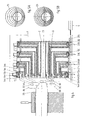
- Fig. 4 is a cross-sectional view of a forming machine for eccentric deformation of a workpiece, said machine comprising four tools.
- Figs. 5A and 5B are front views of a workpiece which has been subjected to one operation and two operations, respectively, by means of the forming machine of Fig. 4 .
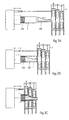
- Fig. 6 is a top plan view of a forming machine which is in particular suitable for deforming relatively long workpieces.
- Figs. 7 and 8 are a front view and a perspective view, respectively, of a so-called carriage for use in a forming machine as shown in Fig. 6 .
- Figs. 9A and 9B are schematic sectional views of the carriage of Figs. 6 - 8 .
- Fig. 10 shows the flow forming process carried out by using the present invention.
- Fig. 11 shows the so-called bottom-closing process carried out by using the present invention.
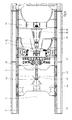
- Figs. 12A - 12D schematically show the rotary deep drawing of a plate-shaped body carried out by means of seven tools.
- Figs. 13A - 13D schematically show the projection of a plate-shaped body by means of six tools.
- Figs. 14A - 14D schematically show a variant of the projection process as carried out in Figs. 13A - 13D .
- FIGs. 1A and 1B schematically show a method and apparatus according to an embodiment according to the present invention.
- a workpiece 1 in this case a metal cylinder, is rotated about an axis of rotation 2 at a certain number of revolutions.
- a deforming head (not shown) is provided, in which five tools 3A - 3E are rotatably mounted.
- Each tool 3 comprises two forming rollers arranged in mirror symmetry with respect to the axis 2. The radial distance from the tools 3 to the axis 2 decreases stepwise towards the rear, seen in the working direction 4.
- Fig. 1A shows the start of the operation, in which the first forming rollers 3A just make contact with the edge of an end of the rotating workpiece 1, whilst Fig. 1B shows the situation after one working cycle, in which the forming rollers 3 have made a full pass in the working direction 4, having deformed the workpiece 1 into a product having five gradually decreasing (in steps) diameters.
- the part having the smallest diameter has been deformed on a mandrel 5 by the final forming rollers 3A, so that the inside diameter of said part is precisely calibrated.
- each tool 3 is positioned closer to the axis of rotation 2 than the preceding tool inter alia depends on the design, the material and the dimensions of the unformed workpiece, of course. In the case of a workpiece having a small wall thickness, it will usually be possible to use larger steps.
- Figs. 2A and 2B show a second embodiment of the present invention, in which the tools 3A - 3C, likewise comprising two forming rollers each in this embodiment, are freely rotatable in holders 6A - 6C.
- the holders 6 are in turn rotatably mounted, about an axis of rotation 2, in a deforming head 7 (schematically shown). Also in this embodiment the radial distance from the tools 3 to the axis 2 decreases in steps towards the rear.
- the holders 6 can be adjusted independently of each other in radial direction. This makes it possible to position said holders 6, and thus the axis of rotation 2 of each of the tools 3, eccentrically with respect to the central axis 8 of the (undeformed as yet) workpiece 1.
- driving means 9 such as a pneumatic or hydraulic cylinder or an electric motor fitted with a spindle
- said workpiece 1 is deformed in one single operation, in which the worked parts obtained are positioned eccentrically with respect to the axis 2.
- the frictional heat which is generated during the deforming operation can be influenced by disposing the forming rollers at an angle with respect to the axis of rotation 2. In the case of an inclined position ( Fig. 2A ) less frictional heat will be generated than in the case of a position at right angles ( Fig. 2B ). This position may be varied in dependence on the heat that is required with a particular operation.
- Figs. 3A - 3C show how parts can be fixed in a workpiece by means of the forming machine as shown in Fig. 2B , e.g. in order for the purpose of manufacturing a catalytic converter for a passenger car.
- a so-called catalytic brick or substrate 11A and an insert member 11B are placed in the workpiece 1 ( Figs. 3A and 3B ).
- the insert member 11B may be supported and placed by means of, for example, an axially adjustable mandrel (not shown) mounted in or through the deforming head 7.
- the workpiece 1 is deformed by a deforming head 7, in which the end of the workpiece 1 is pressed onto the end of the insert member 11B and in which a substantially gastight connection between the two ends is obtained.
- Fig. 4 is a cross-sectional view of a second forming machine for eccentric deformation of a workpiece, which machine comprises four tools 3A - 3D.
- Each tool 3 comprises minimally one forming roller, which is (are) mounted freely rotatable on a separate holder 6A - 6D.
- the holders 6 are arranged in pairs, opposite each other, in four separate rotationally symmetrical housings 12A - 12D, which housings in turn form part of a deforming head 7.
- the first housing 12A comprises a substantially annular, static outer part 13A, in which a, likewise substantially annular, inner part 14A is rotatably mounted in bearings 15A.
- the inner part 14A may e.g.
- a motor 16A (schematically shown), whose drive shaft is fitted with a pinion 17A, which engages in a set of teeth present on the circumference of the inner part 14A.
- an annular element 18A of wedge-shaped section which element 18A mates with an end 19A, likewise of wedge-shaped section, of the respective holder 6A, is present in said inner part 14A.
- driving means 21A are provided, by means of which the housing 12A can be adjusted in axial direction, parallel to the axis of rotation 2, with respect to the other housings 12.
- the other three housings 12B - 12D correspond to a large extent to the first housing 12A, but in addition they comprise a circular cylindrical part 22, whose outside diameter is smaller than the inside diameter of the housing 12 to the left (in the drawing) thereof.
- the housings 12 can also be adjusted in radial direction relative to each other, independently of each other, by means of respective driving mechanisms 23A - 23D, and the axis of rotation 2 of each of the housings 12 can be positioned eccentrically relative to the central axis of (the part as yet undeformed of) a workpiece.
- the annular elements 18B - 18D in turn each comprise a cylindrical part 24, whose outside diameter is smaller than the inside diameter of the inner part 14B - 14D.
- the deforming head 7 comprises driving means 9, by means of which said head 7 can be moved forward and backward in the working direction.
- driving means 9, 20, 21 and 23 include a pneumatic or hydraulic cylinder or an electric motor fitted with a spindle.
- the driving means are not limited to the above examples, of course.
- Figs. 5A and 5B are front views of a workpiece 1 which has been deformed into an (intermediate) product 25 comprising four reduced portions in one working cycle.
- the (intermediate) product 3 can be deformed into a product 25 comprising a total of eight reduced portions in a working cycle, in which the stroke is extended by half the axial distance between the first reduced portions.
- Fig. 4 shows a working process in which the tools are adjusted during the working cycle(s), so that a product having a continuously decreasing diameter, in this case a product having a conical end, is obtained.
- Fig. 6 is a top plan view of a forming machine by means of which also relatively long cylindrical workpieces 1 can be deformed.
- the forming machine comprises a frame 30, which is provided with guide rails 31, 32 on either side, on which a transversely arranged subframe 33 is supported, over which guide rails three so-called carriages can be moved.
- the subframe 33 comprises a clamping head 34, in which a first end of a workpiece 1 can be clamped down and which can be rotated, e.g. by a motor which is accommodated in a housing 35.
- the first carriage 36 is provided with a carrier plate 37, on which four tools 3 are mounted.
- Each tool comprises two forming rollers, which are mounted freely rotatable in holders 38 positioned directly opposite each other.
- Said holders 38 are in turn tiltably mounted, about respective tilting points 39, on radially adjustable supports or slides 40 and they can be tilted in a direction towards the axis of rotation 2 and in a direction away therefrom, using driving means such as electric motors 41 or hydraulic cylinders, which are likewise mounted on respective slides 40.
- driving means such as electric motors 41 or hydraulic cylinders, which are likewise mounted on respective slides 40.
- the slides 40, and thus the holders 38 and the forming rollers can be adjusted in radial direction, using driving means 9.
- the slides 40 are moreover detachably connected to the carrier plate 37, so that the number of slides 40, the number of tools 3 and the positions thereof can easily be adapted to the product to be manufactured.
- the tilting points 39 are located behind the tools 3, seen in the working direction, but said tilting points 39 may also be located at other positions, e.g. in front of or between the tools 3, depending on the operation, or they may even be adjustable. In the latter case the tilting points can be shifted during operation.
- the second carriage 42 comprises a passage 43, in which a centring unit, e.g. a bush (not shown), is present, whose central axis coincides with the axis of rotation 2 and which functions to centre a workpiece present therein with respect to said axis 2.
- the third carriage 44 comprises a so-called tailstock 45, which supports the other end of the workpiece 1 during the operation and which comprises a mandrel 5 or clamping mandrel.
- the second and/or the third carriage can be coupled to the first carriage, e.g. if it is desirable to maintain a substantially constant distance between the first and the second carriage.
- a cylindrical workpiece 1 can be loaded into the forming machine, e.g. by moving the third carriage 44 to the front (to the left in the figure) and moving the first and second carriages 36, 42 to the rear until the distance between the third carriage 44 and the second carriage 42 is greater than the length of the workpiece 1. Then the workpiece 1 is guided through the passage 43 and between the tools 3 with its first end and clamped down in the clamping head 34.
- the mandrel 5 is placed in the second end of the workpiece 1, after which the workpiece 1 is centred, the tools 3 are set and the mandrel 5 is placed into contact with the wall of the workpiece 1. It is also possible to remove the worked workpiece 1 automatically, e.g. by means of a pick and place system, after an operation, when all three carriages are positioned on the left, and load a next workpiece into the machine in the same position of the carriages.
- the outside diameter of the workpiece 1 can be reduced to a smaller, constant outside diameter, e.g. along the full length of the workpiece, by rotating the workpiece 1 about the axis of rotation 2, gradually tilting the tools 3 and moving the slides 40 in radial direction towards the workpiece 1 and initiating a translating movement of the carriages.
- the rear tool 3D will be the first to make contact with the workpiece 1, followed by the third, the second and the first tool, respectively. It is also possible to have 3D and 3C, or even all the tools 3, make contact with the workpiece at the same time. The so-called "escaping" of the material can be suppressed more easily in this way.
- the end of the mandrel 5 is only spaced from the front tool 3 by a small distance at all times, at any rate towards the end of a working operation, in order to support the workpiece 1 up to a point just before the working zone and thus further enhance the degree of stability.
- the mandrel 5 can be used for generating a tensile force in the workpiece 1. Such a tensile force can be used for adjusting the reduction of the wall thickness along the entire length, or practically the entire length, of the product or in particular zones thereof.
- the rate at which the material of the workpiece 1 is pulled from the mandrel 5 will decrease, which will in turn result in a smaller wall thickness.
- the tensile force in the workpiece can be varied by means of the aforesaid centring unit in the passage 43 as well.
- the tensile force can be imposed at the start of the working process, for example, in particular by means of said centring unit, whilst the tensile force can be imposed mainly by the mandrel 5 towards the end, when the workpiece 1 starts to exit from the bush.
- wall thickness and wall thickness variations can be controlled by varying the radial distance between consecutive tools, for instance by tilting the holders and translating the holders in radial direction, preferably simultaneously. By increasing or decreasing the radial distance between the tools, the wall thickness at that location will be reduced or increased respectively.
- Figs. 7 and 8 show variants of the first carriage 36, in which the carriage is shown to be fitted with, respectively, two and six tools.
- Figs. 9A and 9B show the manner in which the tools 3 can be tilted towards the workpiece in carriages as shown in Figs. 7 and 8 and, after the tools have started their working stroke, be moved in radial direction towards the definitive working position.
- a tapered and/or stepped product can be obtained, for example, by adjusting the tools 3 during operation. It is also possible to form two or more products from a workpiece and subsequently separate said products from each other.
- the number of revolutions, the magnitude of the steps and the rate of translation of the tools depend on factors such as the material being used, the outside diameter and the wall thickness of the workpiece and the dimensions of the intended product.
- An aluminium tube having a diameter of 25 cm and a length of 4 m, for example, can e.g. be formed into a conical tube having a diameter which decreases from 16 cm to 8 cm and a length of 7 m.
- Such an operation can usually be carried out at a rotational speed of 200 - 700 revolutions per minute.
- Fig. 10 shows an embodiment in which a cylindrical workpiece 1 is placed onto a mandrel 5 until the closed bottom of said workpiece 1 abuts against the end of the mandrel 5, which workpiece is clamped down by means of a tailstock (not shown) and deformed by means of a flow turning operation.
- Fig. 11 shows how the invention can be used for a process that is also referred to as "bottom closing".
- the open end of a cylindrical workpiece 1 is closed in one operation, using a number of tools 3 which are each mounted on their own slide, and which can thus be moved relative to each other.
- Said adjustable slides are in turn mounted on a support (not shown), which can be pivoted about an adjustable pivot point 39, using driving means as already mentioned before. Since the respective operations of the tools are carried out in quick succession, the risk of adverse effects caused by premature cooling is considerably reduced or even practically eliminated.
- Figs. 12A - 12D show an example of the rotary deep-drawing of a plate-shaped workpiece 1, in this case a metal disc, in which said workpiece 1 is pressed against the central part of a bobbin 46 by means of a tailstock (not shown) and is rotated together with the aforesaid parts.
- the workpiece is deformed by means of five tools 3, which each comprise a number of forming rollers. Said forming rollers are each mounted on a separate slide (not shown), so that the rollers can be moved relative to each other during the deforming process.
- the edge of the workpiece 1 is stabilised by a support or holding-down clamp 47, at least during the initial part of the operation.
- the final tool 3E can directly move along a path corresponding to the outside diameter of the intended product, because the other tools 3A - 3D have sufficiently pre-formed the workpiece 1.
- Fig. 13A - 14D show examples of the so-called projecting of a plate-shaped workpiece 1, likewise a metal disc in this case, which is pressed against a bobbin 46, by means of a tailstock (not shown), and rotated.
- the workpiece is deformed by means of seven tools 3, viz. six discs 3A - 3F and one forming roller 3G, which are mounted on a common tiltable slide.
- the discs mainly function to pre-form the edge of the workpiece relative to the block 46, whilst the forming roller projects the material by means of a flow turning operation.
- Figs. 13A - 14D show examples of the so-called projecting of a plate-shaped workpiece 1, likewise a metal disc in this case, which is pressed against a bobbin 46, by means of a tailstock (not shown), and rotated.
- the workpiece is deformed by means of seven tools 3, viz. six discs 3A - 3F and one forming roller 3G, which
- the tools, the centring means and the like will require no readjustment, and in many cases less residual material, e.g. an undeformed end which was fixed in a loose chuck, or even no residual material at all will remain.
- the forming machines according to the present invention can be operated by a person as well as by a control unit, of course.
- a control unit will be arranged, for example, for controlling the movement of the tools and the workpiece relative to each other, e.g. in axial and radial direction or along X- and Y-coordinates, in accordance with a control programme stored in a memory, in such a manner that the tools will move along one or more desired paths for forming the workpiece into the desired finished product or intermediate product.
- the invention has been explained on the basis of a circular cylindrical metal workpiece in the foregoing, the invention can also be used with workpieces of unround section(s), such as oval, substantially triangular or multilobal sections.
- the invention can furthermore be used for hot forming as well as for cold forming.
- tool as used within the framework of the present invention inter alia comprises a single forming roller and sets of two or more such forming rollers, which take up substantially the same axial position with respect to the workpiece.
Landscapes
- Engineering & Computer Science (AREA)
- Mechanical Engineering (AREA)
- Shaping Metal By Deep-Drawing, Or The Like (AREA)
- Extrusion Moulding Of Plastics Or The Like (AREA)
- Pens And Brushes (AREA)
- Moulds For Moulding Plastics Or The Like (AREA)
- Blow-Moulding Or Thermoforming Of Plastics Or The Like (AREA)
- Press Drives And Press Lines (AREA)
- Bending Of Plates, Rods, And Pipes (AREA)
Abstract
Description
- The invention relates to a method and a forming machine suitable for manufacturing a product having varying diameters from a workpiece, such as a metal cylinder or plate, in which the workpiece is clamped down in a clamping device, the workpiece and a first tool are rotated about an axis of rotation relative to each other, the workpiece is deformed by means of said first tool by placing the tool into contact with the workpiece and moving the workpiece and/or the tool in a direction along, i.e. parallel to or having a component parallel to, the axis of rotation.
- Such a method and apparatus are known, e.g. from
EP 0 916 426 . Said publication describes how one end of a cylindrical workpiece is worked by clamping down said workpiece in a clamping device (indicated by numeral 12 inFig. 1 ofEP 0 916 426 ) and deforming said ends by means of three forming rollers (28), which are mounted on a rotary member (24). Said forming rollers (28) rotate in the same plane and are pressed against the workpiece at three locations which are evenly distributed over the circumference of the workpiece, after which said rollers move along a number of paths along the workpiece so as to deform the workpiece in steps. - For the sake of completeness, attention is drawn to
DE 23 27 664DE 1964 401 , in which methods and apparatuses are described for flow pressing cylindrical tubes, i.e. tubes having a constant diameter. The methods and apparatuses according to these documents are unsuitable for manufacturing a product having varying diameters. - The object of the invention is to provide an improved method and forming machine.
- In order to accomplish that objective, the method and the forming machine referred to in the first paragraph are characterized as defined in
claims - Thus, parts of the workpiece that have been deformed by the first tool are deformed by one or more subsequent tools almost immediately. As a result, the material, such as aluminium or steel, will have a relatively very limited opportunity, if any, to harden, so that the next operation will proceed relatively easily and the risk of the material being damaged or adversely affected is considerably reduced.
- Preferably, each tool comprises two or more forming rollers, between which the workpiece is retained while being worked and which occupy substantially the same axial position with respect to the workpiece. It is possible to impose relatively large as well as relatively small diameter changes by means of forming rollers. Such rollers are preferably freely rotatable about an axis which extends either horizontally or at an angle with respect to the aforesaid axis of rotation. Furthermore, it is preferred that most or all of the tools form part of one and the same deforming head, or that they are at any rate positioned relatively close together. The question as to the most suitable spacing between successive tools, at least between the positions at which the tools make contact with the workpiece, depends on the properties of the workpiece, of course, and on the nature of the working process to be carried out. In many cases said spacing will vary between 1 and 30 cm.
- If the material and the dimensions of the workpiece and the intended product (frequently a semifinished product) allow so, the number of working cycles can be reduced to one, if desired. A surface that has been worked once will not be worked anew in that case, so that the load to which the material is subjected will remain limited. In addition to that the programming of any control equipment that may be provided will be significantly simpler, in particular because it will not be necessary to take the shape and the behaviour of various intermediate forms into account.
- For the sake of completeness it is noted that British patent application No.
238,960 - Further, attention is drawn to
US 5,428,980 , in which a workpiece is deformed with a first forming roller and glazed with a second roller. A second forming roller is not described. - The invention will be explained hereinafter with reference to the figures, which show a number of embodiments of the method and the forming machine according to the present invention.
-
Figs. 1A and 1B schematically show the deformation of one end of a cylindrical workpiece by means of five tools. -
Figs. 2A and 2B show the eccentric deformation of one end of a workpiece by means of three tools. -
Figs. 3A - 3C show the fixing of an insert member in a cylindrical workpiece, using a method comparable to the method as used inFigs. 2A and 2B . -
Fig. 4 is a cross-sectional view of a forming machine for eccentric deformation of a workpiece, said machine comprising four tools. -
Figs. 5A and 5B are front views of a workpiece which has been subjected to one operation and two operations, respectively, by means of the forming machine ofFig. 4 . -
Fig. 6 is a top plan view of a forming machine which is in particular suitable for deforming relatively long workpieces. -
Figs. 7 and8 are a front view and a perspective view, respectively, of a so-called carriage for use in a forming machine as shown inFig. 6 . -
Figs. 9A and 9B are schematic sectional views of the carriage ofFigs. 6 - 8 . -
Fig. 10 shows the flow forming process carried out by using the present invention. -
Fig. 11 shows the so-called bottom-closing process carried out by using the present invention. -
Figs. 12A - 12D schematically show the rotary deep drawing of a plate-shaped body carried out by means of seven tools. -
Figs. 13A - 13D schematically show the projection of a plate-shaped body by means of six tools. -
Figs. 14A - 14D schematically show a variant of the projection process as carried out inFigs. 13A - 13D . - Parts which are identical or which have the same or substantially the same function will be indicated by the same numerals as much as possible hereinafter.
-
Figs. 1A and 1B schematically show a method and apparatus according to an embodiment according to the present invention. Aworkpiece 1, in this case a metal cylinder, is rotated about an axis ofrotation 2 at a certain number of revolutions. Subsequently a deforming head (not shown) is provided, in which fivetools 3A - 3E are rotatably mounted. Eachtool 3 comprises two forming rollers arranged in mirror symmetry with respect to theaxis 2. The radial distance from thetools 3 to theaxis 2 decreases stepwise towards the rear, seen in theworking direction 4. -
Fig. 1A shows the start of the operation, in which the first formingrollers 3A just make contact with the edge of an end of the rotatingworkpiece 1, whilstFig. 1B shows the situation after one working cycle, in which the formingrollers 3 have made a full pass in the workingdirection 4, having deformed theworkpiece 1 into a product having five gradually decreasing (in steps) diameters. The part having the smallest diameter has been deformed on amandrel 5 by the final formingrollers 3A, so that the inside diameter of said part is precisely calibrated. - The magnitude of the steps by which each
tool 3 is positioned closer to the axis ofrotation 2 than the preceding tool inter alia depends on the design, the material and the dimensions of the unformed workpiece, of course. In the case of a workpiece having a small wall thickness, it will usually be possible to use larger steps. -
Figs. 2A and 2B show a second embodiment of the present invention, in which thetools 3A - 3C, likewise comprising two forming rollers each in this embodiment, are freely rotatable in holders 6A - 6C. The holders 6 are in turn rotatably mounted, about an axis ofrotation 2, in a deforming head 7 (schematically shown). Also in this embodiment the radial distance from thetools 3 to theaxis 2 decreases in steps towards the rear. The holders 6 can be adjusted independently of each other in radial direction. This makes it possible to position said holders 6, and thus the axis ofrotation 2 of each of thetools 3, eccentrically with respect to thecentral axis 8 of the (undeformed as yet)workpiece 1. - By rotating the holders 6 and moving the deforming
head 7 in the workingdirection 4, using driving means 9 (schematically shown) such as a pneumatic or hydraulic cylinder or an electric motor fitted with a spindle, over aworkpiece 1 clamped down in a fixed clamping head 10 (schematically shown), saidworkpiece 1 is deformed in one single operation, in which the worked parts obtained are positioned eccentrically with respect to theaxis 2. - For the sake of completeness it is noted that the frictional heat which is generated during the deforming operation can be influenced by disposing the forming rollers at an angle with respect to the axis of
rotation 2. In the case of an inclined position (Fig. 2A ) less frictional heat will be generated than in the case of a position at right angles (Fig. 2B ). This position may be varied in dependence on the heat that is required with a particular operation. -
Figs. 3A - 3C show how parts can be fixed in a workpiece by means of the forming machine as shown inFig. 2B , e.g. in order for the purpose of manufacturing a catalytic converter for a passenger car. - First a so-called catalytic brick or
substrate 11A and aninsert member 11B are placed in the workpiece 1 (Figs. 3A and 3B ). Theinsert member 11B may be supported and placed by means of, for example, an axially adjustable mandrel (not shown) mounted in or through the deforminghead 7. Following that, theworkpiece 1 is deformed by a deforminghead 7, in which the end of theworkpiece 1 is pressed onto the end of theinsert member 11B and in which a substantially gastight connection between the two ends is obtained. -
Fig. 4 is a cross-sectional view of a second forming machine for eccentric deformation of a workpiece, which machine comprises fourtools 3A - 3D. Eachtool 3 comprises minimally one forming roller, which is (are) mounted freely rotatable on a separate holder 6A - 6D. The holders 6 are arranged in pairs, opposite each other, in four separate rotationallysymmetrical housings 12A - 12D, which housings in turn form part of a deforminghead 7. Thefirst housing 12A comprises a substantially annular, static outer part 13A, in which a, likewise substantially annular,inner part 14A is rotatably mounted in bearings 15A. Theinner part 14A may e.g. be driven by means of a motor 16A (schematically shown), whose drive shaft is fitted with apinion 17A, which engages in a set of teeth present on the circumference of theinner part 14A. In addition, anannular element 18A of wedge-shaped section, whichelement 18A mates with anend 19A, likewise of wedge-shaped section, of the respective holder 6A, is present in saidinner part 14A. By moving theannular element 18A to the left or the right (in the drawing), using driving means 20A, the holders 6A, and thus the forming rollers mounted thereon, are moved radially inwardly or outwardly, respectively. Furthermore, driving means 21A are provided, by means of which thehousing 12A can be adjusted in axial direction, parallel to the axis ofrotation 2, with respect to the other housings 12. - The other three housings 12B - 12D correspond to a large extent to the
first housing 12A, but in addition they comprise a circularcylindrical part 22, whose outside diameter is smaller than the inside diameter of the housing 12 to the left (in the drawing) thereof. As a result, the housings 12 can also be adjusted in radial direction relative to each other, independently of each other, by means of respective driving mechanisms 23A - 23D, and the axis ofrotation 2 of each of the housings 12 can be positioned eccentrically relative to the central axis of (the part as yet undeformed of) a workpiece. - The annular elements 18B - 18D in turn each comprise a cylindrical part 24, whose outside diameter is smaller than the inside diameter of the inner part 14B - 14D. Furthermore, the deforming
head 7 comprises driving means 9, by means of which saidhead 7 can be moved forward and backward in the working direction. Examples of the aforesaid driving means 9, 20, 21 and 23 include a pneumatic or hydraulic cylinder or an electric motor fitted with a spindle. The driving means are not limited to the above examples, of course. -
Figs. 5A and 5B are front views of aworkpiece 1 which has been deformed into an (intermediate)product 25 comprising four reduced portions in one working cycle. By subsequently adjusting thetools 3 in outward direction, the (intermediate)product 3 can be deformed into aproduct 25 comprising a total of eight reduced portions in a working cycle, in which the stroke is extended by half the axial distance between the first reduced portions. It stands to reason that it is possible to adapt inter alia the number oftools 3, the number of working cycles and the degree to which the tools are adjusted to the required product. ThusFig. 4 shows a working process in which the tools are adjusted during the working cycle(s), so that a product having a continuously decreasing diameter, in this case a product having a conical end, is obtained. -
Fig. 6 is a top plan view of a forming machine by means of which also relatively longcylindrical workpieces 1 can be deformed. The forming machine comprises aframe 30, which is provided withguide rails subframe 33 is supported, over which guide rails three so-called carriages can be moved. - The
subframe 33 comprises a clampinghead 34, in which a first end of aworkpiece 1 can be clamped down and which can be rotated, e.g. by a motor which is accommodated in ahousing 35. - The
first carriage 36 is provided with acarrier plate 37, on which fourtools 3 are mounted. Each tool comprises two forming rollers, which are mounted freely rotatable inholders 38 positioned directly opposite each other. Saidholders 38 are in turn tiltably mounted, about respective tilting points 39, on radially adjustable supports or slides 40 and they can be tilted in a direction towards the axis ofrotation 2 and in a direction away therefrom, using driving means such aselectric motors 41 or hydraulic cylinders, which are likewise mounted onrespective slides 40. Theslides 40, and thus theholders 38 and the forming rollers, can be adjusted in radial direction, using driving means 9. In the illustrated embodiment, theslides 40 are moreover detachably connected to thecarrier plate 37, so that the number ofslides 40, the number oftools 3 and the positions thereof can easily be adapted to the product to be manufactured. In the illustrated embodiment, the tilting points 39 are located behind thetools 3, seen in the working direction, but said tilting points 39 may also be located at other positions, e.g. in front of or between thetools 3, depending on the operation, or they may even be adjustable. In the latter case the tilting points can be shifted during operation. - The
second carriage 42 comprises apassage 43, in which a centring unit, e.g. a bush (not shown), is present, whose central axis coincides with the axis ofrotation 2 and which functions to centre a workpiece present therein with respect to saidaxis 2. Thethird carriage 44 comprises a so-calledtailstock 45, which supports the other end of theworkpiece 1 during the operation and which comprises amandrel 5 or clamping mandrel. Depending on the operation, the second and/or the third carriage can be coupled to the first carriage, e.g. if it is desirable to maintain a substantially constant distance between the first and the second carriage. - A
cylindrical workpiece 1 can be loaded into the forming machine, e.g. by moving thethird carriage 44 to the front (to the left in the figure) and moving the first andsecond carriages third carriage 44 and thesecond carriage 42 is greater than the length of theworkpiece 1. Then theworkpiece 1 is guided through thepassage 43 and between thetools 3 with its first end and clamped down in the clampinghead 34. Themandrel 5 is placed in the second end of theworkpiece 1, after which theworkpiece 1 is centred, thetools 3 are set and themandrel 5 is placed into contact with the wall of theworkpiece 1. It is also possible to remove the workedworkpiece 1 automatically, e.g. by means of a pick and place system, after an operation, when all three carriages are positioned on the left, and load a next workpiece into the machine in the same position of the carriages. - The outside diameter of the
workpiece 1 can be reduced to a smaller, constant outside diameter, e.g. along the full length of the workpiece, by rotating theworkpiece 1 about the axis ofrotation 2, gradually tilting thetools 3 and moving theslides 40 in radial direction towards theworkpiece 1 and initiating a translating movement of the carriages. Therear tool 3D will be the first to make contact with theworkpiece 1, followed by the third, the second and the first tool, respectively. It is also possible to have 3D and 3C, or even all thetools 3, make contact with the workpiece at the same time. The so-called "escaping" of the material can be suppressed more easily in this way. - Preferably, the end of the
mandrel 5 is only spaced from thefront tool 3 by a small distance at all times, at any rate towards the end of a working operation, in order to support theworkpiece 1 up to a point just before the working zone and thus further enhance the degree of stability. In addition, themandrel 5 can be used for generating a tensile force in theworkpiece 1. Such a tensile force can be used for adjusting the reduction of the wall thickness along the entire length, or practically the entire length, of the product or in particular zones thereof. As the force exerted on the workpiece by means of themandrel 5 increases, the rate at which the material of theworkpiece 1 is pulled from themandrel 5 will decrease, which will in turn result in a smaller wall thickness. It is noted that the tensile force in the workpiece can be varied by means of the aforesaid centring unit in thepassage 43 as well. Thus the tensile force can be imposed at the start of the working process, for example, in particular by means of said centring unit, whilst the tensile force can be imposed mainly by themandrel 5 towards the end, when theworkpiece 1 starts to exit from the bush. - Incidentally, wall thickness and wall thickness variations can be controlled by varying the radial distance between consecutive tools, for instance by tilting the holders and translating the holders in radial direction, preferably simultaneously. By increasing or decreasing the radial distance between the tools, the wall thickness at that location will be reduced or increased respectively.
-
Figs. 7 and8 show variants of thefirst carriage 36, in which the carriage is shown to be fitted with, respectively, two and six tools. -
Figs. 9A and 9B show the manner in which thetools 3 can be tilted towards the workpiece in carriages as shown inFigs. 7 and8 and, after the tools have started their working stroke, be moved in radial direction towards the definitive working position. Using the apparatus as shown inFigs. 6-9B , a tapered and/or stepped product can be obtained, for example, by adjusting thetools 3 during operation. It is also possible to form two or more products from a workpiece and subsequently separate said products from each other. - The number of revolutions, the magnitude of the steps and the rate of translation of the tools depend on factors such as the material being used, the outside diameter and the wall thickness of the workpiece and the dimensions of the intended product. An aluminium tube having a diameter of 25 cm and a length of 4 m, for example, can e.g. be formed into a conical tube having a diameter which decreases from 16 cm to 8 cm and a length of 7 m. Such an operation can usually be carried out at a rotational speed of 200 - 700 revolutions per minute.
-
Fig. 10 shows an embodiment in which acylindrical workpiece 1 is placed onto amandrel 5 until the closed bottom of saidworkpiece 1 abuts against the end of themandrel 5, which workpiece is clamped down by means of a tailstock (not shown) and deformed by means of a flow turning operation. This makes it possible to control the surface quality of the inner wall and, more in particular, prevent porosity of said inner wall. In addition to that it is possible to manufacture a finished product having a variable wall thickness in a single working cycle by adjusting the tools in radial direction during operation. -
Fig. 11 shows how the invention can be used for a process that is also referred to as "bottom closing". In this process, the open end of acylindrical workpiece 1 is closed in one operation, using a number oftools 3 which are each mounted on their own slide, and which can thus be moved relative to each other. Said adjustable slides are in turn mounted on a support (not shown), which can be pivoted about anadjustable pivot point 39, using driving means as already mentioned before. Since the respective operations of the tools are carried out in quick succession, the risk of adverse effects caused by premature cooling is considerably reduced or even practically eliminated. -
Figs. 12A - 12D show an example of the rotary deep-drawing of a plate-shapedworkpiece 1, in this case a metal disc, in which saidworkpiece 1 is pressed against the central part of abobbin 46 by means of a tailstock (not shown) and is rotated together with the aforesaid parts. The workpiece is deformed by means of fivetools 3, which each comprise a number of forming rollers. Said forming rollers are each mounted on a separate slide (not shown), so that the rollers can be moved relative to each other during the deforming process. The edge of theworkpiece 1 is stabilised by a support or holding-down clamp 47, at least during the initial part of the operation. In the illustrated example, thefinal tool 3E can directly move along a path corresponding to the outside diameter of the intended product, because theother tools 3A - 3D have sufficiently pre-formed theworkpiece 1. -
Fig. 13A - 14D show examples of the so-called projecting of a plate-shapedworkpiece 1, likewise a metal disc in this case, which is pressed against abobbin 46, by means of a tailstock (not shown), and rotated. The workpiece is deformed by means of seventools 3, viz. sixdiscs 3A - 3F and one formingroller 3G, which are mounted on a common tiltable slide. The discs mainly function to pre-form the edge of the workpiece relative to theblock 46, whilst the forming roller projects the material by means of a flow turning operation.Figs. 14A - 14D show how the forming roller on the one hand and the six discs on the other hand are mounted on either side of theblock 46, each on aseparate holder 47, 48, which holders can be moved in the X-direction and the Y-direction by means of two respective slides. For more details with regard to the projection process, reference is made toEP 0 774 308 . - If the workpieces are deformed in only one working cycle in the forming machines as described above, the tools, the centring means and the like will require no readjustment, and in many cases less residual material, e.g. an undeformed end which was fixed in a loose chuck, or even no residual material at all will remain.
- The forming machines according to the present invention can be operated by a person as well as by a control unit, of course. Such a control unit will be arranged, for example, for controlling the movement of the tools and the workpiece relative to each other, e.g. in axial and radial direction or along X- and Y-coordinates, in accordance with a control programme stored in a memory, in such a manner that the tools will move along one or more desired paths for forming the workpiece into the desired finished product or intermediate product.
- Although the invention has been explained on the basis of a circular cylindrical metal workpiece in the foregoing, the invention can also be used with workpieces of unround section(s), such as oval, substantially triangular or multilobal sections. The invention can furthermore be used for hot forming as well as for cold forming.
- The term "tool" as used within the framework of the present invention inter alia comprises a single forming roller and sets of two or more such forming rollers, which take up substantially the same axial position with respect to the workpiece.
- Consequently, the invention is not restricted to the embodiments as described above, which can be varied in many ways within the scope of the invention as defined in the claims.
Claims (15)
- Method for manufacturing a product having varying diameters from a workpiece (1), such as a metal cylinder or plate, in which the workpiece (1) is clamped down in a clamping device (10, 34), the workpiece (1) and a first tool (3A) are rotated about an axis of rotation (2) relative to each other, the workpiece (1) is deformed by means of said first tool (3A) by placing the tool (3A) into contact with the workpiece (1) and moving the workpiece (1) and/or the tool (3A) in a direction along said axis of rotation (2), wherein at least a second tool (3B) is placed into contact with the workpiece (1) at a position behind the first tool (3A), said workpiece (1) being also deformed by means of said second tool (3B), characterized in that the tools (3A, 3B) are moved relative to each other during the working.
- Method according to claim 1, wherein at least a third tool (3B) is placed into contact with the workpiece (1) at a position behind the second tool (3B).
- Method according to claim 1 or 2, wherein each tool (3) comprises two or more forming rollers, between which the workpiece (1) is retained while being worked.
- Method according to any of the preceding claims, wherein the workpiece (1) is formed into a finished or semifinished product in only one working cycle.
- Method according to any of the preceding claims, wherein a tensile force is exerted on the workpiece (1).
- Method according to claim 5, wherein said tensile force is varied during said working.
- Method according to any of the preceding claims, wherein at least one of the tools is adjusted in radial direction during said working.
- Method according to any of the preceding being claims, wherein the workpiece (1) has an open end, said end being closed by means of the tools (3), preferably in one operation.
- Method according to any of the preceding claims, wherein at least one of the tools (3A - 3C) is positioned eccentrically with respect to the central axis (8) of the workpiece (1).
- Forming machine suitable for manufacturing products having varying diameters, said forming machine comprising at least a clamping device (10, 34) for clamping down a workpiece (1), such as a metal cylinder or plate, a first tool (3A), which can be placed into contact with the workpiece (1) while being worked, means for rotating the workpiece (1) and the tool (3A) about an axis of rotation (2) relative to each other, and means for moving the workpiece (1) and/or the tool (3A) in a direction along said axis of rotation (2), wherein the forming machine furthermore comprises at least a second tool (3B) disposed behind said first tool (3A), which can be placed into contact with the workpiece (1), characterized in that the tools (3) can be moved relative to each other during the working.
- Forming machine according to claim 10, comprising at least a third tool (3C) disposed behind said second tool (3B).
- Forming machine according to claims 12 or 13, wherein each tool (3) comprises two or more forming rollers, between which the workpiece (1) can be retained.
- Forming machine according to any of the claims 10 - 12, wherein two or more forming rollers associated with different tools (3) are mounted on a common holder (38).
- Forming machine according to claim 13, wherein said holder (38) is mounted in or on the forming machine in such manner as to be capable of rotation about an axis (39) which crosses said axis of rotation (2), and/or radial translation.
- Forming machine according to any of the claims 10 - 14, comprising a mandrel (5) or bush to be placed in or around, respectively, an unworked part of the workpiece (1), and by means of which a tensile force can be exerted on the workpiece.
Priority Applications (1)
| Application Number | Priority Date | Filing Date | Title |
|---|---|---|---|
| SI200332082T SI1994997T1 (en) | 2002-01-17 | 2003-01-17 | Method and forming machine for manufacturing a product having varying diameters |
Applications Claiming Priority (3)
| Application Number | Priority Date | Filing Date | Title |
|---|---|---|---|
| NL1019773 | 2002-01-17 | ||
| NL1020109 | 2002-03-04 | ||
| EP03701934A EP1469957B1 (en) | 2002-01-17 | 2003-01-17 | Method and forming machine for manufacturing a product having various diameters |
Related Parent Applications (2)
| Application Number | Title | Priority Date | Filing Date |
|---|---|---|---|
| EP03701934A Division EP1469957B1 (en) | 2002-01-17 | 2003-01-17 | Method and forming machine for manufacturing a product having various diameters |
| EP03701934.6 Division | 2003-01-17 |
Related Child Applications (1)
| Application Number | Title | Priority Date | Filing Date |
|---|---|---|---|
| EP10182116.3 Division-Into | 2010-09-29 |
Publications (3)
| Publication Number | Publication Date |
|---|---|
| EP1994997A2 EP1994997A2 (en) | 2008-11-26 |
| EP1994997A3 EP1994997A3 (en) | 2008-12-03 |
| EP1994997B1 true EP1994997B1 (en) | 2011-09-07 |
Family
ID=26643428
Family Applications (2)
| Application Number | Title | Priority Date | Filing Date |
|---|---|---|---|
| EP08162981A Expired - Lifetime EP1994997B1 (en) | 2002-01-17 | 2003-01-17 | Method and forming machine for manufacturing a product having varying diameters |
| EP03701934A Expired - Lifetime EP1469957B1 (en) | 2002-01-17 | 2003-01-17 | Method and forming machine for manufacturing a product having various diameters |
Family Applications After (1)
| Application Number | Title | Priority Date | Filing Date |
|---|---|---|---|
| EP03701934A Expired - Lifetime EP1469957B1 (en) | 2002-01-17 | 2003-01-17 | Method and forming machine for manufacturing a product having various diameters |
Country Status (16)
| Country | Link |
|---|---|
| US (2) | US8117877B2 (en) |
| EP (2) | EP1994997B1 (en) |
| JP (1) | JP4928714B2 (en) |
| KR (1) | KR100973178B1 (en) |
| AT (2) | ATE523272T1 (en) |
| AU (1) | AU2003202828A1 (en) |
| CA (1) | CA2474019C (en) |
| DE (1) | DE60323203D1 (en) |
| DK (2) | DK1469957T3 (en) |
| ES (2) | ES2372644T3 (en) |
| MX (1) | MXPA04006984A (en) |
| NL (1) | NL1022416C2 (en) |
| PT (2) | PT1994997E (en) |
| SI (2) | SI1469957T1 (en) |
| WO (1) | WO2003059547A1 (en) |
| ZA (1) | ZA200405415B (en) |
Families Citing this family (33)
| Publication number | Priority date | Publication date | Assignee | Title |
|---|---|---|---|---|
| DE10229073C1 (en) * | 2002-06-28 | 2003-12-18 | Contitech Luftfedersyst Gmbh | The assembly for the continuous production of reinforced tubular blanks has coupled mandrels to be coated with the rubber/plastics and reinforcement layers, to be separated and stripped for vulcanizing free of the mandrels |
| JP4531648B2 (en) * | 2005-07-08 | 2010-08-25 | 日本スピンドル製造株式会社 | Tapered steel pipe manufacturing method |
| KR100825686B1 (en) * | 2006-01-25 | 2008-04-29 | 주식회사동양강철 | The aluminum alloy sub-frame for a car, and the manrfacturing method of the same |
| DK178066B1 (en) * | 2006-05-16 | 2015-04-20 | Bang & Olufsen As | Optimized metal printing using lathe |
| JP4822928B2 (en) * | 2006-05-18 | 2011-11-24 | 株式会社ユタカ技研 | Molding method and molding apparatus |
| JP4876740B2 (en) * | 2006-07-04 | 2012-02-15 | 日産自動車株式会社 | Fine shape processing apparatus, fine shape processing method, and sliding member |
| EP2077132A1 (en) | 2008-01-02 | 2009-07-08 | Boehringer Ingelheim Pharma GmbH & Co. KG | Dispensing device, storage device and method for dispensing a formulation |
| JP5328198B2 (en) * | 2008-03-28 | 2013-10-30 | 山陽特殊製鋼株式会社 | Ring rolling method for ring-shaped products with complex surface profile in the axial direction |
| EP2236227B1 (en) * | 2009-03-30 | 2013-12-18 | Boehringer Ingelheim International GmbH | Forming tool with a rotatable base body |
| EP2236224B1 (en) * | 2009-03-30 | 2013-03-06 | Boehringer Ingelheim International GmbH | Forming tool with a rotatable basis body for forming an inhalator cartridge and use of such a tool |
| JP5670421B2 (en) | 2009-03-31 | 2015-02-18 | ベーリンガー インゲルハイム インターナショナル ゲゼルシャフト ミット ベシュレンクテル ハフツング | Component surface coating method |
| EP2432531B1 (en) | 2009-05-18 | 2019-03-06 | Boehringer Ingelheim International GmbH | Adapter, inhalation device and nebulizer |
| CA2781792C (en) | 2009-11-25 | 2019-04-02 | Boehringer Ingelheim International Gmbh | Nebulizer |
| WO2011064163A1 (en) | 2009-11-25 | 2011-06-03 | Boehringer Ingelheim International Gmbh | Nebulizer |
| US10016568B2 (en) | 2009-11-25 | 2018-07-10 | Boehringer Ingelheim International Gmbh | Nebulizer |
| WO2011160932A1 (en) | 2010-06-24 | 2011-12-29 | Boehringer Ingelheim International Gmbh | Nebulizer |
| EP2588273B1 (en) * | 2010-07-01 | 2017-01-11 | Hegenscheidt-MFD GmbH & Co. KG | Machine for deep-rolling axles |
| US8935946B1 (en) * | 2010-09-07 | 2015-01-20 | Davor Petricio Yaksic | Variable diameter nozzle, joint and rod forming using cam rollers |
| EP2694220B1 (en) | 2011-04-01 | 2020-05-06 | Boehringer Ingelheim International GmbH | Medical device comprising a container |
| US9827384B2 (en) | 2011-05-23 | 2017-11-28 | Boehringer Ingelheim International Gmbh | Nebulizer |
| WO2013152894A1 (en) | 2012-04-13 | 2013-10-17 | Boehringer Ingelheim International Gmbh | Atomiser with coding means |
| US20140102158A1 (en) * | 2012-10-16 | 2014-04-17 | Bailey Tool & Manufacturing Company | Method of tube-necking spinning and apparatus therefor |
| JP6061762B2 (en) * | 2013-04-03 | 2017-01-18 | 株式会社 クニテック | Spinning processing method and spinning processing apparatus |
| EP3030298B1 (en) | 2013-08-09 | 2017-10-11 | Boehringer Ingelheim International GmbH | Nebulizer |
| PL2835146T3 (en) | 2013-08-09 | 2021-04-06 | Boehringer Ingelheim International Gmbh | Nebulizer |
| US10195374B2 (en) | 2014-05-07 | 2019-02-05 | Boehringer Ingelheim International Gmbh | Container, nebulizer and use |
| ES2913297T3 (en) | 2014-05-07 | 2022-06-01 | Boehringer Ingelheim Int | nebulizer |
| US10722666B2 (en) | 2014-05-07 | 2020-07-28 | Boehringer Ingelheim International Gmbh | Nebulizer with axially movable and lockable container and indicator |
| CN104353699B (en) * | 2014-10-11 | 2016-09-21 | 浙江久德不锈钢型材有限公司 | Steel pipe mould |
| US10603761B2 (en) * | 2016-06-06 | 2020-03-31 | United Technologies Corporation | Deep roll peening system and method |
| CN106111772B (en) * | 2016-06-28 | 2017-11-10 | 上海交通大学 | The adjustable vertical spinning machine device of spinning roller pose |
| CN110548797B (en) | 2019-09-16 | 2020-07-07 | 芜湖西诺普汽车零部件科技有限公司 | Coreless spinning processing method for large-proportion multi-time reducing hollow shaft |
| CN115921604B (en) * | 2022-11-17 | 2023-11-21 | 上海槎南工贸发展有限公司 | Anti-offset punching-breaking and bending integrated intelligent sheet metal device |
Family Cites Families (71)
| Publication number | Priority date | Publication date | Assignee | Title |
|---|---|---|---|---|
| US555915A (en) * | 1896-03-03 | Flue-expander | ||
| US1212489A (en) * | 1916-03-10 | 1917-01-16 | Thaddeus A Jackson | Can-surface presser and evener. |
| US1379087A (en) * | 1920-05-22 | 1921-05-24 | Thomas J Dixon | Multiple expander |
| US1417980A (en) * | 1921-03-23 | 1922-05-30 | Lovejoy Tool Works | Multiple expander |
| US1499533A (en) * | 1922-06-05 | 1924-07-01 | John A Katzenmeyer | Reducing cylindrical bodies |
| US1615306A (en) * | 1923-10-01 | 1927-01-25 | Adrian R Reynolds | Tool for opening collapsed pipes or casings |
| GB238960A (en) | 1924-05-29 | 1925-08-31 | John Alexander Katzenmeyer | Improvements in continuous rolling mills |
| US1671994A (en) * | 1926-09-09 | 1928-06-05 | Spun Steel Corp | Metal-spinning apparatus |
| US2164724A (en) * | 1936-07-25 | 1939-07-04 | Severin Jose | Rolling mill for enlarging hollow bodies |
| US2388643A (en) * | 1943-01-02 | 1945-11-06 | Bliss E W Co | Apparatus for swaging tubular blanks |
| US2645954A (en) * | 1949-03-30 | 1953-07-21 | Servel Inc | Thread forming method and apparatus |
| US2757706A (en) * | 1951-05-09 | 1956-08-07 | John M Johnston | Apparatus and method for forming seamless flexible tubing |
| US2800942A (en) * | 1954-10-08 | 1957-07-30 | Parker | Apparatus for performing multiple metal working operations on pipe |
| US2761336A (en) * | 1955-06-29 | 1956-09-04 | Calumet & Hecla | Apparatus for finning metal tubes |
| US3006225A (en) * | 1957-07-08 | 1961-10-31 | Industrial Nucleonics Corp | Special mill controls |
| US3323339A (en) * | 1963-10-30 | 1967-06-06 | Phelps Dodge Copper Prod | Method and apparatus for corrugating tubes |
| LU46907A1 (en) * | 1964-09-08 | 1966-03-08 | ||
| US3363442A (en) * | 1965-05-25 | 1968-01-16 | North American Aviation Inc | Tube tapering device |
| US3427846A (en) * | 1966-05-16 | 1969-02-18 | Technoimpex Magyar Gepipari Ku | Hydraulic metal press |
| GB1394105A (en) | 1969-09-17 | 1975-05-14 | Bomco | Process and apparatus for producing cup-shaped thinwalled metal wares |
| DE1964401B2 (en) | 1969-12-23 | 1973-09-06 | FLOW PRESSURE MACHINE | |
| US3762195A (en) * | 1970-03-09 | 1973-10-02 | Hitachi Ltd | Thickness control apparatus for rolling mill |
| US3727445A (en) * | 1970-08-24 | 1973-04-17 | Ashtabula Bow Socket Co | Method and appatatus for forming a blank |
| US3745801A (en) * | 1972-03-02 | 1973-07-17 | Carrier Corp | Multiple tube finning apparatus |
| DE2327664A1 (en) | 1973-05-30 | 1974-12-19 | Strobel Christian | HIGH PERFORMANCE PROCESS FOR STRETCHING AND FOR PULLING IN PIPE BODIES AND DEVICE FOR ITS APPLICATION TO THE MANUFACTURING OF CONTAINERS AND PIPES MADE OF STEEL AND NON-FERROUS METALS |
| JPS51143566A (en) * | 1975-06-04 | 1976-12-09 | Fuji Machine Mfg | Method and equipment for making metallic bats |
| US4006617A (en) * | 1975-11-24 | 1977-02-08 | The Boeing Company | Method and apparatus for roll forming tapered structural members |
| US4055064A (en) * | 1976-01-08 | 1977-10-25 | Schow Virgle L | Muffler and tail pipe expander and cleaner |
| JPS5294450U (en) * | 1976-01-12 | 1977-07-14 | ||
| JPS5294450A (en) | 1976-02-03 | 1977-08-09 | Tokyu Co Ltd | Ham having taste and flavor of soy sauce |
| JPS5382653A (en) | 1976-12-28 | 1978-07-21 | Nhk Spring Co Ltd | Spinning device for pipe |
| US4248072A (en) * | 1978-07-25 | 1981-02-03 | Aichi Steel Works, Limited | Method of and apparatus for producing plate material having uniform width and lengthwise thickness variation |
| JPS56136218A (en) * | 1980-03-29 | 1981-10-24 | Aichi Steel Works Ltd | Manufacturing apparatus for product having sectional shape varying in longitudinal direction |
| US4498322A (en) * | 1980-06-30 | 1985-02-12 | Toropov Gennady A | Thread-rolling tool |
| JPS59193724A (en) | 1983-04-18 | 1984-11-02 | Mitsubishi Heavy Ind Ltd | Spinning device |
| DE3423223C1 (en) | 1984-06-21 | 1986-02-06 | Mannesmann AG, 4000 Düsseldorf | Apparatus for swaging the end of a tubular metal piece |
| JPS62142032A (en) | 1985-12-16 | 1987-06-25 | Sumitomo Light Metal Ind Ltd | Rotary working method for thin wall metallic tube |
| JPS6340631A (en) * | 1986-04-09 | 1988-02-22 | Takayama Seisakusho:Kk | Rolling method |
| US4765058A (en) * | 1987-08-05 | 1988-08-23 | Carrier Corporation | Apparatus for manufacturing enhanced heat transfer surface |
| JPH01110478A (en) | 1987-10-19 | 1989-04-27 | Murata Mach Ltd | Package transfer device |
| JPH0763795B2 (en) * | 1988-01-16 | 1995-07-12 | 株式会社神戸製鋼所 | Method for setting control conditions for rolling rolls in manufacturing taper rod |
| DE3820742A1 (en) * | 1988-06-18 | 1989-12-21 | Man Technologie Gmbh | METHOD FOR REGULATING THE ADJUSTMENT OF PRESSURE ROLLING REELS WITH REGARD TO A PIPE CYLINDRICAL WORKPIECE |
| JP2548799B2 (en) * | 1989-05-29 | 1996-10-30 | 日鋼特機株式会社 | Tube diameter reducing machine |
| JPH0671636B2 (en) * | 1989-11-09 | 1994-09-14 | 日本発条株式会社 | Leaf spring manufacturing apparatus and leaf spring manufacturing method |
| JP2528341Y2 (en) * | 1991-08-07 | 1997-03-12 | 住友重機械工業株式会社 | Roller apron for beam blank and rectangular slab in continuous casting equipment |
| JP2678533B2 (en) | 1991-08-26 | 1997-11-17 | 次男 飯高 | Device for manufacturing thin film cap, method for manufacturing the same, and thin film cap made of aluminum for covering the mouth of a beverage bottle manufactured by the device |
| US5428980A (en) * | 1991-08-26 | 1995-07-04 | Iidaka; Tsuguo | Method and apparatus for producing cap for drink bottle |
| JPH05294450A (en) | 1992-04-20 | 1993-11-09 | Akoo Ceramic:Kk | Tile loader into container and method thereof |
| EP0593799B1 (en) * | 1992-10-19 | 1996-01-03 | ZEPPELIN-Metallwerke GmbH | Method of and device for shaping a blank of sheet |
| US6216512B1 (en) * | 1993-11-16 | 2001-04-17 | Sango Co., Ltd. | Method and apparatus for forming a processed portion of a workpiece |
| US5598729A (en) * | 1994-10-26 | 1997-02-04 | Tandem Systems, Inc. | System and method for constructing wall of a tube |
| JP3034447B2 (en) * | 1995-09-06 | 2000-04-17 | トヨタ自動車株式会社 | Gear multi-stage rolling device |
| NL1001675C2 (en) | 1995-11-17 | 1997-05-21 | Johan Massee | Method and device for making a product by forcing. |
| US5782324A (en) * | 1995-12-27 | 1998-07-21 | Dayton Walther Corporation | Composite brake drum and method for producing same |
| ES2148807T3 (en) * | 1996-08-14 | 2000-10-16 | Wf Maschinenbau Blechformtech | PROCEDURE AND DEVICE FOR THE MANUFACTURE OF AN EXTERNAL TOOTHED GEAR PART. |
| JPH10156445A (en) | 1996-11-27 | 1998-06-16 | Mitsubishi Electric Corp | Manufacture of reflecting plate and its device and reflecting plate manufacturing die |
| US5937516A (en) * | 1996-12-13 | 1999-08-17 | General Motors Corporation | Method for spin forming articles |
| JP3492165B2 (en) | 1997-10-03 | 2004-02-03 | 三菱重工業株式会社 | Cap molding equipment |
| JP2957153B2 (en) | 1997-11-11 | 1999-10-04 | 株式会社三五 | Pipe end forming method and apparatus |
| US6018972A (en) | 1997-11-11 | 2000-02-01 | Sango Co., Ltd | Method and apparatus for forming an end portion of a cylindrical member |
| JP4086394B2 (en) | 1998-12-24 | 2008-05-14 | 株式会社三五 | End material forming method and apparatus for tube material |
| DE19908995A1 (en) | 1999-03-02 | 2000-09-07 | Ecoroll Ag Werkzeugtechnik | Forming tool for forming rotationally symmetrical workpieces |
| JP2000301246A (en) | 1999-04-19 | 2000-10-31 | Tensei Kogyo Kk | Drawing device of metal tubular body |
| US6212926B1 (en) * | 1999-04-21 | 2001-04-10 | Tandem Systems, Inc. | Method for spin forming a tube |
| JP4393621B2 (en) | 1999-05-10 | 2010-01-06 | 株式会社三五 | Pipe end forming method and apparatus |
| JP3377974B2 (en) * | 2000-01-12 | 2003-02-17 | サムテック株式会社 | Molding method of molded article having external teeth |
| DE10005438A1 (en) * | 2000-02-08 | 2001-08-16 | Psw Press Und Schmiedewerk Gmb | Method to manufacture coupling tooth on one-part gear; involves guiding one or more profiled non-cutting shaping tools in position towards the work piece to rotate with respect to work piece |
| JP3500109B2 (en) | 2000-03-30 | 2004-02-23 | 株式会社三五 | Exhaust gas treatment device manufacturing method |
| EP1322446A1 (en) * | 2000-07-17 | 2003-07-02 | Victaulic Company of America | Pipe preparation device |
| US6442988B1 (en) * | 2001-05-01 | 2002-09-03 | Alcan International Limited | Methods of spin forming initially cylindrical containers and the like |
| US6697556B1 (en) * | 2002-09-17 | 2004-02-24 | Alcoa Fujilura Limited | Method for section reducing a steel tube to achieve excess fiber length of an elongate bundle of optical fibers contained within the tube |
-
2003
- 2003-01-17 AT AT08162981T patent/ATE523272T1/en active
- 2003-01-17 WO PCT/NL2003/000030 patent/WO2003059547A1/en active Application Filing
- 2003-01-17 EP EP08162981A patent/EP1994997B1/en not_active Expired - Lifetime
- 2003-01-17 ES ES08162981T patent/ES2372644T3/en not_active Expired - Lifetime
- 2003-01-17 DK DK03701934T patent/DK1469957T3/en active
- 2003-01-17 DK DK08162981.8T patent/DK1994997T3/en active
- 2003-01-17 DE DE60323203T patent/DE60323203D1/en not_active Expired - Lifetime
- 2003-01-17 SI SI200331439T patent/SI1469957T1/en unknown
- 2003-01-17 US US10/501,758 patent/US8117877B2/en not_active Expired - Fee Related
- 2003-01-17 PT PT08162981T patent/PT1994997E/en unknown
- 2003-01-17 AU AU2003202828A patent/AU2003202828A1/en not_active Abandoned
- 2003-01-17 NL NL1022416A patent/NL1022416C2/en not_active IP Right Cessation
- 2003-01-17 JP JP2003559699A patent/JP4928714B2/en not_active Expired - Fee Related
- 2003-01-17 PT PT03701934T patent/PT1469957E/en unknown
- 2003-01-17 CA CA2474019A patent/CA2474019C/en not_active Expired - Fee Related
- 2003-01-17 EP EP03701934A patent/EP1469957B1/en not_active Expired - Lifetime
- 2003-01-17 KR KR1020047011117A patent/KR100973178B1/en not_active IP Right Cessation
- 2003-01-17 AT AT03701934T patent/ATE406225T1/en active
- 2003-01-17 MX MXPA04006984A patent/MXPA04006984A/en active IP Right Grant
- 2003-01-17 SI SI200332082T patent/SI1994997T1/en unknown
- 2003-01-17 ES ES03701934T patent/ES2312748T3/en not_active Expired - Lifetime
-
2004
- 2004-07-07 ZA ZA2004/05415A patent/ZA200405415B/en unknown
-
2012
- 2012-02-07 US US13/367,897 patent/US8539805B2/en not_active Expired - Fee Related
Also Published As
| Publication number | Publication date |
|---|---|
| US8117877B2 (en) | 2012-02-21 |
| US20050144998A1 (en) | 2005-07-07 |
| ES2372644T3 (en) | 2012-01-25 |
| SI1994997T1 (en) | 2012-01-31 |
| JP2005525937A (en) | 2005-09-02 |
| WO2003059547A1 (en) | 2003-07-24 |
| CA2474019A1 (en) | 2003-07-24 |
| AU2003202828A1 (en) | 2003-07-30 |
| PT1994997E (en) | 2011-12-22 |
| US20120131975A1 (en) | 2012-05-31 |
| JP4928714B2 (en) | 2012-05-09 |
| ES2312748T3 (en) | 2009-03-01 |
| DE60323203D1 (en) | 2008-10-09 |
| KR100973178B1 (en) | 2010-07-30 |
| ATE523272T1 (en) | 2011-09-15 |
| MXPA04006984A (en) | 2005-06-08 |
| EP1994997A2 (en) | 2008-11-26 |
| PT1469957E (en) | 2008-11-28 |
| US8539805B2 (en) | 2013-09-24 |
| EP1994997A3 (en) | 2008-12-03 |
| EP1469957A1 (en) | 2004-10-27 |
| ZA200405415B (en) | 2005-08-31 |
| NL1022416C2 (en) | 2003-07-18 |
| SI1469957T1 (en) | 2009-02-28 |
| DK1469957T3 (en) | 2009-01-05 |
| EP1469957B1 (en) | 2008-08-27 |
| KR20040111346A (en) | 2004-12-31 |
| CA2474019C (en) | 2011-04-26 |
| ATE406225T1 (en) | 2008-09-15 |
| DK1994997T3 (en) | 2012-01-02 |
Similar Documents
| Publication | Publication Date | Title |
|---|---|---|
| EP1994997B1 (en) | Method and forming machine for manufacturing a product having varying diameters | |
| CN110312579B (en) | Method and apparatus for spin forming | |
| JP2957154B2 (en) | Pipe end forming method and apparatus | |
| CN110405094B (en) | Machine tool for necking two ends of pipe and machining method thereof | |
| JP2005525937A5 (en) | ||
| JP2957153B2 (en) | Pipe end forming method and apparatus | |
| EP1939488B1 (en) | Method for processing a metal band, a continuous metal band and pushbelt in which the metal band is used | |
| US20040050130A1 (en) | Method and forming machine for deforming a hollow workpiece | |
| JP2000190030A (en) | Method and device for molding pipe material end part | |
| US10569321B2 (en) | Device and method for flow-forming workpieces | |
| JP5099955B2 (en) | Molding machine and method for deforming hollow processed member | |
| JP4370089B2 (en) | Diameter expansion method and apparatus for expanding pipe member | |
| WO2001034318A1 (en) | Method for making seamless wheel rims | |
| US5946959A (en) | Process for producing annular workpieces from metal with a profiled cross section and a rolling facility for carrying out the method | |
| RU2201831C2 (en) | Bottom spinning method and apparatus for performing the same | |
| RU2175901C2 (en) | Method for making hollow axially symmetrical parts such as bottoms | |
| EP1110641A1 (en) | Forming machine, method for forming a product and exhaust system or pulley comprising such a product | |
| CA2007577A1 (en) | Process and machine for the forming of metal tubes into conical or tapered bodies | |
| JP2003088932A (en) | Rotary plastic worked body, rotary plastic working method and its apparatus |
Legal Events
| Date | Code | Title | Description |
|---|---|---|---|
| PUAI | Public reference made under article 153(3) epc to a published international application that has entered the european phase |
Free format text: ORIGINAL CODE: 0009012 |
|
| PUAL | Search report despatched |
Free format text: ORIGINAL CODE: 0009013 |
|
| AC | Divisional application: reference to earlier application |
Ref document number: 1469957 Country of ref document: EP Kind code of ref document: P |
|
| AK | Designated contracting states |
Kind code of ref document: A2 Designated state(s): AT BE BG CH CY CZ DE DK EE ES FI FR GB GR HU IE IT LI LU MC NL PT SE SI SK TR |
|
| AX | Request for extension of the european patent |
Extension state: AL LT LV MK RO |
|
| AK | Designated contracting states |
Kind code of ref document: A3 Designated state(s): AT BE BG CH CY CZ DE DK EE ES FI FR GB GR HU IE IT LI LU MC NL PT SE SI SK TR |
|
| AX | Request for extension of the european patent |
Extension state: AL LT LV MK RO |
|
| 17P | Request for examination filed |
Effective date: 20090306 |
|
| 17Q | First examination report despatched |
Effective date: 20090401 |
|
| AKX | Designation fees paid |
Designated state(s): AT BE BG CH CY CZ DE DK EE ES FI FR GB GR HU IE IT LI LU MC NL PT SE SI SK TR |
|
| GRAP | Despatch of communication of intention to grant a patent |
Free format text: ORIGINAL CODE: EPIDOSNIGR1 |
|
| RTI1 | Title (correction) |
Free format text: METHOD AND FORMING MACHINE FOR MANUFACTURING A PRODUCT HAVING VARYING DIAMETERS |
|
| GRAS | Grant fee paid |
Free format text: ORIGINAL CODE: EPIDOSNIGR3 |
|
| GRAA | (expected) grant |
Free format text: ORIGINAL CODE: 0009210 |
|
| REG | Reference to a national code |
Ref country code: GB Ref legal event code: FG4D |
|
| REG | Reference to a national code |
Ref country code: CH Ref legal event code: EP |
|
| REG | Reference to a national code |
Ref country code: IE Ref legal event code: FG4D |
|
| REG | Reference to a national code |
Ref country code: DE Ref legal event code: R096 Ref document number: 60338317 Country of ref document: DE Effective date: 20111103 |
|
| REG | Reference to a national code |
Ref country code: NL Ref legal event code: T3 |
|
| REG | Reference to a national code |
Ref country code: PT Ref legal event code: SC4A Free format text: AVAILABILITY OF NATIONAL TRANSLATION Effective date: 20111202 |
|
| REG | Reference to a national code |
Ref country code: SE Ref legal event code: TRGR |
|
| REG | Reference to a national code |
Ref country code: DK Ref legal event code: T3 |
|
| REG | Reference to a national code |
Ref country code: ES Ref legal event code: FG2A Ref document number: 2372644 Country of ref document: ES Kind code of ref document: T3 Effective date: 20120125 |
|
| PG25 | Lapsed in a contracting state [announced via postgrant information from national office to epo] |
Ref country code: CY Free format text: LAPSE BECAUSE OF FAILURE TO SUBMIT A TRANSLATION OF THE DESCRIPTION OR TO PAY THE FEE WITHIN THE PRESCRIBED TIME-LIMIT Effective date: 20110907 |
|
| REG | Reference to a national code |
Ref country code: GR Ref legal event code: EP Ref document number: 20110402888 Country of ref document: GR Effective date: 20120206 |
|
| REG | Reference to a national code |
Ref country code: SK Ref legal event code: T3 Ref document number: E 11169 Country of ref document: SK |
|
| PG25 | Lapsed in a contracting state [announced via postgrant information from national office to epo] |
Ref country code: EE Free format text: LAPSE BECAUSE OF FAILURE TO SUBMIT A TRANSLATION OF THE DESCRIPTION OR TO PAY THE FEE WITHIN THE PRESCRIBED TIME-LIMIT Effective date: 20110907 |
|
| PGFP | Annual fee paid to national office [announced via postgrant information from national office to epo] |
Ref country code: TR Payment date: 20120116 Year of fee payment: 10 |
|
| PGFP | Annual fee paid to national office [announced via postgrant information from national office to epo] |
Ref country code: IT Payment date: 20120123 Year of fee payment: 10 |
|
| PLBE | No opposition filed within time limit |
Free format text: ORIGINAL CODE: 0009261 |
|
| STAA | Information on the status of an ep patent application or granted ep patent |
Free format text: STATUS: NO OPPOSITION FILED WITHIN TIME LIMIT |
|
| REG | Reference to a national code |
Ref country code: HU Ref legal event code: AG4A Ref document number: E013519 Country of ref document: HU |
|
| 26N | No opposition filed |
Effective date: 20120611 |
|
| PG25 | Lapsed in a contracting state [announced via postgrant information from national office to epo] |
Ref country code: MC Free format text: LAPSE BECAUSE OF NON-PAYMENT OF DUE FEES Effective date: 20120131 |
|
| REG | Reference to a national code |
Ref country code: DE Ref legal event code: R097 Ref document number: 60338317 Country of ref document: DE Effective date: 20120611 |
|
| PGFP | Annual fee paid to national office [announced via postgrant information from national office to epo] |
Ref country code: LU Payment date: 20130131 Year of fee payment: 11 |
|
| PGFP | Annual fee paid to national office [announced via postgrant information from national office to epo] |
Ref country code: FR Payment date: 20130211 Year of fee payment: 11 Ref country code: GB Payment date: 20130125 Year of fee payment: 11 Ref country code: CH Payment date: 20130125 Year of fee payment: 11 Ref country code: BG Payment date: 20130130 Year of fee payment: 11 Ref country code: SE Payment date: 20130129 Year of fee payment: 11 Ref country code: DK Payment date: 20130125 Year of fee payment: 11 Ref country code: ES Payment date: 20130128 Year of fee payment: 11 Ref country code: CZ Payment date: 20130109 Year of fee payment: 11 Ref country code: FI Payment date: 20130129 Year of fee payment: 11 Ref country code: HU Payment date: 20130117 Year of fee payment: 11 Ref country code: DE Payment date: 20130129 Year of fee payment: 11 Ref country code: IE Payment date: 20130125 Year of fee payment: 11 |
|
| PGFP | Annual fee paid to national office [announced via postgrant information from national office to epo] |
Ref country code: BE Payment date: 20130128 Year of fee payment: 11 Ref country code: GR Payment date: 20130128 Year of fee payment: 11 Ref country code: SI Payment date: 20130103 Year of fee payment: 11 Ref country code: NL Payment date: 20130130 Year of fee payment: 11 Ref country code: SK Payment date: 20130102 Year of fee payment: 11 |
|
| PGFP | Annual fee paid to national office [announced via postgrant information from national office to epo] |
Ref country code: PT Payment date: 20130104 Year of fee payment: 11 Ref country code: AT Payment date: 20130103 Year of fee payment: 11 |
|
| REG | Reference to a national code |
Ref country code: PT Ref legal event code: MM4A Free format text: LAPSE DUE TO NON-PAYMENT OF FEES Effective date: 20140717 |
|
| BERE | Be: lapsed |
Owner name: QUIDE B.V. Effective date: 20140131 |
|
| REG | Reference to a national code |
Ref country code: DE Ref legal event code: R119 Ref document number: 60338317 Country of ref document: DE |
|
| REG | Reference to a national code |
Ref country code: NL Ref legal event code: V1 Effective date: 20140801 |
|
| PG25 | Lapsed in a contracting state [announced via postgrant information from national office to epo] |
Ref country code: LU Free format text: LAPSE BECAUSE OF NON-PAYMENT OF DUE FEES Effective date: 20140117 |
|
| REG | Reference to a national code |
Ref country code: CH Ref legal event code: PL |
|
| REG | Reference to a national code |
Ref country code: DK Ref legal event code: EBP Effective date: 20140131 |
|
| REG | Reference to a national code |
Ref country code: AT Ref legal event code: MM01 Ref document number: 523272 Country of ref document: AT Kind code of ref document: T Effective date: 20140117 |
|
| REG | Reference to a national code |
Ref country code: SE Ref legal event code: EUG |
|
| GBPC | Gb: european patent ceased through non-payment of renewal fee |
Effective date: 20140117 |
|
| REG | Reference to a national code |
Ref country code: SK Ref legal event code: MM4A Ref document number: E 11169 Country of ref document: SK Effective date: 20140117 |
|
| REG | Reference to a national code |
Ref country code: GR Ref legal event code: ML Ref document number: 20110402888 Country of ref document: GR Effective date: 20140801 |
|
| REG | Reference to a national code |
Ref country code: SI Ref legal event code: KO00 Effective date: 20140909 |
|
| PG25 | Lapsed in a contracting state [announced via postgrant information from national office to epo] |
Ref country code: BG Free format text: LAPSE BECAUSE OF NON-PAYMENT OF DUE FEES Effective date: 20140930 Ref country code: LI Free format text: LAPSE BECAUSE OF NON-PAYMENT OF DUE FEES Effective date: 20140131 Ref country code: DE Free format text: LAPSE BECAUSE OF NON-PAYMENT OF DUE FEES Effective date: 20140801 Ref country code: GR Free format text: LAPSE BECAUSE OF NON-PAYMENT OF DUE FEES Effective date: 20140801 Ref country code: CZ Free format text: LAPSE BECAUSE OF NON-PAYMENT OF DUE FEES Effective date: 20140117 Ref country code: CH Free format text: LAPSE BECAUSE OF NON-PAYMENT OF DUE FEES Effective date: 20140131 Ref country code: FI Free format text: LAPSE BECAUSE OF NON-PAYMENT OF DUE FEES Effective date: 20140117 Ref country code: NL Free format text: LAPSE BECAUSE OF NON-PAYMENT OF DUE FEES Effective date: 20140801 |
|
| REG | Reference to a national code |
Ref country code: FR Ref legal event code: ST Effective date: 20140930 |
|
| REG | Reference to a national code |
Ref country code: IE Ref legal event code: MM4A |
|
| REG | Reference to a national code |
Ref country code: DE Ref legal event code: R119 Ref document number: 60338317 Country of ref document: DE Effective date: 20140801 |
|
| PG25 | Lapsed in a contracting state [announced via postgrant information from national office to epo] |
Ref country code: FR Free format text: LAPSE BECAUSE OF NON-PAYMENT OF DUE FEES Effective date: 20140131 Ref country code: HU Free format text: LAPSE BECAUSE OF NON-PAYMENT OF DUE FEES Effective date: 20140118 Ref country code: SK Free format text: LAPSE BECAUSE OF NON-PAYMENT OF DUE FEES Effective date: 20140117 Ref country code: SI Free format text: LAPSE BECAUSE OF NON-PAYMENT OF DUE FEES Effective date: 20140118 Ref country code: SE Free format text: LAPSE BECAUSE OF NON-PAYMENT OF DUE FEES Effective date: 20140118 Ref country code: AT Free format text: LAPSE BECAUSE OF NON-PAYMENT OF DUE FEES Effective date: 20140117 Ref country code: GB Free format text: LAPSE BECAUSE OF NON-PAYMENT OF DUE FEES Effective date: 20140117 |
|
| PG25 | Lapsed in a contracting state [announced via postgrant information from national office to epo] |
Ref country code: PT Free format text: LAPSE BECAUSE OF NON-PAYMENT OF DUE FEES Effective date: 20140717 |
|
| PG25 | Lapsed in a contracting state [announced via postgrant information from national office to epo] |
Ref country code: IE Free format text: LAPSE BECAUSE OF NON-PAYMENT OF DUE FEES Effective date: 20140117 Ref country code: BE Free format text: LAPSE BECAUSE OF NON-PAYMENT OF DUE FEES Effective date: 20140131 Ref country code: DK Free format text: LAPSE BECAUSE OF NON-PAYMENT OF DUE FEES Effective date: 20140131 |
|
| REG | Reference to a national code |
Ref country code: ES Ref legal event code: FD2A Effective date: 20150327 |
|
| PG25 | Lapsed in a contracting state [announced via postgrant information from national office to epo] |
Ref country code: ES Free format text: LAPSE BECAUSE OF NON-PAYMENT OF DUE FEES Effective date: 20140118 |
|
| PG25 | Lapsed in a contracting state [announced via postgrant information from national office to epo] |
Ref country code: IT Free format text: LAPSE BECAUSE OF NON-PAYMENT OF DUE FEES Effective date: 20140117 |
|
| PG25 | Lapsed in a contracting state [announced via postgrant information from national office to epo] |
Ref country code: TR Free format text: LAPSE BECAUSE OF NON-PAYMENT OF DUE FEES Effective date: 20140117 |