EP2694220B1 - Medical device comprising a container - Google Patents
Medical device comprising a container Download PDFInfo
- Publication number
- EP2694220B1 EP2694220B1 EP12710275.4A EP12710275A EP2694220B1 EP 2694220 B1 EP2694220 B1 EP 2694220B1 EP 12710275 A EP12710275 A EP 12710275A EP 2694220 B1 EP2694220 B1 EP 2694220B1
- Authority
- EP
- European Patent Office
- Prior art keywords
- container
- seal
- holder
- cap
- tube
- Prior art date
- Legal status (The legal status is an assumption and is not a legal conclusion. Google has not performed a legal analysis and makes no representation as to the accuracy of the status listed.)
- Active
Links
Images


Classifications
-
- B—PERFORMING OPERATIONS; TRANSPORTING
- B05—SPRAYING OR ATOMISING IN GENERAL; APPLYING FLUENT MATERIALS TO SURFACES, IN GENERAL
- B05B—SPRAYING APPARATUS; ATOMISING APPARATUS; NOZZLES
- B05B11/00—Single-unit hand-held apparatus in which flow of contents is produced by the muscular force of the operator at the moment of use
- B05B11/0005—Components or details
- B05B11/0008—Sealing or attachment arrangements between sprayer and container
- B05B11/0013—Attachment arrangements comprising means cooperating with the inner surface of the container
-
- A—HUMAN NECESSITIES
- A61—MEDICAL OR VETERINARY SCIENCE; HYGIENE
- A61M—DEVICES FOR INTRODUCING MEDIA INTO, OR ONTO, THE BODY; DEVICES FOR TRANSDUCING BODY MEDIA OR FOR TAKING MEDIA FROM THE BODY; DEVICES FOR PRODUCING OR ENDING SLEEP OR STUPOR
- A61M15/00—Inhalators
- A61M15/0001—Details of inhalators; Constructional features thereof
- A61M15/0021—Mouthpieces therefor
- A61M15/0025—Mouthpieces therefor with caps
- A61M15/0026—Hinged caps
-
- A—HUMAN NECESSITIES
- A61—MEDICAL OR VETERINARY SCIENCE; HYGIENE
- A61M—DEVICES FOR INTRODUCING MEDIA INTO, OR ONTO, THE BODY; DEVICES FOR TRANSDUCING BODY MEDIA OR FOR TAKING MEDIA FROM THE BODY; DEVICES FOR PRODUCING OR ENDING SLEEP OR STUPOR
- A61M15/00—Inhalators
- A61M15/0028—Inhalators using prepacked dosages, one for each application, e.g. capsules to be perforated or broken-up
- A61M15/003—Inhalators using prepacked dosages, one for each application, e.g. capsules to be perforated or broken-up using capsules, e.g. to be perforated or broken-up
- A61M15/0033—Details of the piercing or cutting means
- A61M15/0035—Piercing means
- A61M15/0036—Piercing means hollow piercing means
-
- A—HUMAN NECESSITIES
- A61—MEDICAL OR VETERINARY SCIENCE; HYGIENE
- A61M—DEVICES FOR INTRODUCING MEDIA INTO, OR ONTO, THE BODY; DEVICES FOR TRANSDUCING BODY MEDIA OR FOR TAKING MEDIA FROM THE BODY; DEVICES FOR PRODUCING OR ENDING SLEEP OR STUPOR
- A61M15/00—Inhalators
- A61M15/0065—Inhalators with dosage or measuring devices
-
- B—PERFORMING OPERATIONS; TRANSPORTING
- B05—SPRAYING OR ATOMISING IN GENERAL; APPLYING FLUENT MATERIALS TO SURFACES, IN GENERAL
- B05B—SPRAYING APPARATUS; ATOMISING APPARATUS; NOZZLES
- B05B11/00—Single-unit hand-held apparatus in which flow of contents is produced by the muscular force of the operator at the moment of use
- B05B11/0005—Components or details
- B05B11/0037—Containers
- B05B11/0054—Cartridges, i.e. containers specially designed for easy attachment to or easy removal from the rest of the sprayer
-
- B—PERFORMING OPERATIONS; TRANSPORTING
- B05—SPRAYING OR ATOMISING IN GENERAL; APPLYING FLUENT MATERIALS TO SURFACES, IN GENERAL
- B05B—SPRAYING APPARATUS; ATOMISING APPARATUS; NOZZLES
- B05B11/00—Single-unit hand-held apparatus in which flow of contents is produced by the muscular force of the operator at the moment of use
- B05B11/01—Single-unit hand-held apparatus in which flow of contents is produced by the muscular force of the operator at the moment of use characterised by the means producing the flow
- B05B11/02—Membranes or pistons acting on the contents inside the container, e.g. follower pistons
- B05B11/026—Membranes separating the content remaining in the container from the atmospheric air to compensate underpressure inside the container
-
- B—PERFORMING OPERATIONS; TRANSPORTING
- B05—SPRAYING OR ATOMISING IN GENERAL; APPLYING FLUENT MATERIALS TO SURFACES, IN GENERAL
- B05B—SPRAYING APPARATUS; ATOMISING APPARATUS; NOZZLES
- B05B11/00—Single-unit hand-held apparatus in which flow of contents is produced by the muscular force of the operator at the moment of use
- B05B11/01—Single-unit hand-held apparatus in which flow of contents is produced by the muscular force of the operator at the moment of use characterised by the means producing the flow
- B05B11/10—Pump arrangements for transferring the contents from the container to a pump chamber by a sucking effect and forcing the contents out through the dispensing nozzle
- B05B11/109—Pump arrangements for transferring the contents from the container to a pump chamber by a sucking effect and forcing the contents out through the dispensing nozzle the dispensing stroke being affected by the stored energy of a spring
- B05B11/1091—Pump arrangements for transferring the contents from the container to a pump chamber by a sucking effect and forcing the contents out through the dispensing nozzle the dispensing stroke being affected by the stored energy of a spring being first hold in a loaded state by locking means or the like, then released
Definitions
- the present invention relates to devices for administering liquid, medical formulations, the fluid connection of these devices with, for example, propellant-free containers which contain the respective liquid, and the sealing of the containers and the fluidic connection between the container and the device to the outside.
- the invention relates to smaller portable devices such as, for example, hand-operated atomizers or injectors, such as are used for the inhalation or injection of liquid pharmaceutical formulations.
- a large number of medical devices and atomizers which are operated with a liquid are known from the prior art. Most of the liquid is filled into storage jars or containers that contain multiple units of the liquid for administration with the device. To remove the liquid or the units in the form of measured portions from the container, a fluidic connection between the device and the container is established, depending on the application, permanently or interruptibly. The fluidic connection is established either through sampling lines such as cannulas or hoses that are inserted into the container, or by exposing openings in the container and connecting them to associated channels inside the device.
- the latter group also includes systems such as the Metered Dose Inhaler (MDIs) containing propellant gas, in which a prechamber or dosing chamber is integrated in the container and via a switching mechanism - for example in the form of a movable plunger with corresponding bushings - the antechamber is connected either to the liquid supply or to the device.
- MDIs Metered Dose Inhaler
- a prechamber or dosing chamber is integrated in the container and via a switching mechanism - for example in the form of a movable plunger with corresponding bushings - the antechamber is connected either to the liquid supply or to the device.
- a switching mechanism for example in the form of a movable plunger with corresponding bushings - the antechamber is connected either to the liquid supply or to the device.
- Common to all these systems is the need to seal the connection point between the container and the device - be it statically or dynamically moved - to the outside, so that no liquid escapes
- the requirements for the sealing of the connection between the device and the container depend, in particular in the case of hand-held devices such as atomizers, on the pharmaceutical formulation to be administered and their concentration, the solvent used or on climatic conditions at the place of use and can therefore vary widely.
- the interface from container to device must be tight and resistant to all substances from the pharmaceutical formulation.
- the formulation can contain not only liquid and solid but also gaseous constituents, gas tightness generally being a higher requirement than liquid tightness.
- Some pharmaceutical formulations contain volatile substances such as ethanol, which is often used as a solvent. If a volatile substance escapes from the container separately, the concentration of the formulation can change. Depending on the composition of the formulation, the concentration of an active ingredient in the solution can be increased or a dissolved substance can crystallize out.
- Such substances primarily escape in gaseous form: These substances, which naturally have an increased vapor pressure, quickly change partially into the gas phase, particularly in the event of climatic changes, even within the container. Under certain circumstances, even small ones Temperature increases or pressure drops in the vicinity of the container lead to increased gas formation in the container, and this gas can escape in part through a seal designed primarily for liquid tightness.
- a mechanical, miniaturized high-pressure atomizer with which liquid pharmaceutical formulations for inhalation are atomized from a container containing several units of the formulation and in the interior of which the fluid path is statically and dynamically sealed, is shown in US Pat WO97 / 12687A1 and WO2009 / 047173A2 known.
- a liquid pharmaceutical formulation is made from a rigid container inserted into the atomizer with a collapsible inner bag, as in FIG WO00 / 49988A2 disclosed, conveyed out of the inner bag by means of a piston pump driven by a screw-push gear and atomized by means of a spring-driven pressure pump through a micro-structured nozzle to form a respirable aerosol.
- WO00 / 49988A2 shows a cartridge which is closed with a stopper and is filled with liquid and is connected to the connecting part of a removal device or an atomizer.
- the plug has an immersion nozzle with a funnel-shaped centered guide for connecting a removal nozzle belonging to the connecting part and shown in the form of a tube.
- the plug forms a press fit with the inserted extraction nozzle (see WO96 / 06011A1 for variants of this plug in the form of a container cap).
- Cartridge and connecting part are connected via a plug-in connection, in which several snap hooks on the connecting part engage in a circumferential groove in the upper area of the cartridge.
- the cartridge or the upper open end of the immersion nozzle is sealed with a sealing film, while the end of the immersion nozzle facing the interior of the cartridge is provided with a membrane, which is pierced or opened when the extraction nozzle is inserted.
- a container with foil bags is shown as the primary packaging for liquids.
- the container comprises a collapsible film bag (for example made of a composite film that contains a metal film), on which a stable flange is arranged, which can be connected to a removal element.
- the one-part or multi-part flange is equipped with a guide channel for the removal element, which surrounds it, for example, in a press fit or against which an annular seal in the flange seals.
- WO2006 / 087516A1 shows a sealing arrangement for connecting the valve stem of a pressurized container to an atomizer or to a switching device for an atomizer.
- This sealing arrangement includes a first sealing part which lies directly on the outlet of the container, ie on the end face of the valve stem, and a second sealing part which is spaced apart from it and which seals the side wall of the valve stem.
- the first seal part is a flat seal with a through hole and the second is an O-ring seal.
- the two seals are their sealing function redundant to each other. Both are held together by a fixed cap including a spacer and thus form a multi-part sealing arrangement.
- the present invention has for its object to provide a device improved over the prior art - in particular a hand-held device such as an atomizer or injector - for administering medical formulations from a container, in which the connection point between the container and the device in accordance with the formulation used is liquid-tight and is sealed gas-tight.
- the sealing system should not have any permeability to the liquid and gaseous substances of the formulation or should not allow diffusion leakages, especially if the formulations contain substances with high vapor pressure, such as ethanol.
- the device with the sealing system at the junction of the container and the device should be particularly suitable for the provision of measured quantities of liquid.
- the devices equipped with these sealing systems should be as independent as possible of the later use, ie in particular independent of climatic conditions and in particular independent of climatic fluctuations or of the particular use or therapy that may be individually defined for the user. Depending on the therapy, the number of operations per device per day can vary from device to device depending on the active ingredient formulation and dosage. Furthermore, the device with sealing system should be suitable for mass production. In particular, the sealing system should be as inexpensive as possible with regard to the number and type of its components and it should be able to be assembled reliably in mass production without damage.
- this object is achieved by a device for administering a liquid medical formulation, which is located in a container inserted into the device.
- the container is pushed onto a rigid tube inside the device, which is connected to a holder which receives the container in the device, for example by being pinched.
- the container has an insertion point at which there is a first seal in the form of a mating seal between the container and a section of the rigid tube which is used to remove liquid from the container.
- the second seal additionally seals the fluidic connection between the device and the container from the environment. The two successive seals prevent the unwanted escape of liquid and gas from the container and / or the penetration of gas into the container better than the first seal alone.
- a feature of the present invention is that the first seal is substantially sealed to the liquid components of the medical formulation in the container and the second seal is substantially sealed to gases.
- This will make the Requirements for the tightness of the system as a whole are divided into different requirements for two separate seals.
- This offers the advantage that the individual requirements can be met in a targeted manner without being forced to use a single, possibly expensive, or technically complex solution, or one that is defective in terms of partial aspects.
- a first seal on the container side can be designed primarily to retain the liquid in the container while taking full account of the requirements for the material compatibility of the liquid and sealing material.
- the requirement of the gas tightness of the fluid connection of the device with the container can be specifically solved by means of the second seal.
- this second seal which can also be referred to as a gas phase seal
- the material can be selected primarily from the aspect of gas permeability, without the materials used here necessarily having to be chemically compatible with the liquid in the container. This is particularly relevant for systems in which the container contains volatile substances such as ethanol. Volatile substances show high diffusion through the finest channels due to their vapor pressure, as well as significant diffusion through a large number of plastic materials in the event of permanent fluid contact.
- a further feature of the present invention is that while the first seal is formed by a mating seal or press fit between the container - preferably a partial area of an insertion funnel integrated in a container cap - and the tube serving for the removal of liquid, the second seal is formed by only one additional component or an additional sealing layer is formed between the container or the container cap and the holder of the container in the device.
- the sealing layer the material of which is preferably softer than that of the container cap and holder, can be applied, for example, by injection molding either on the side of the holder facing the container or on the inner edge of the insertion point on the container or in the upper region of the container cap.
- both seals - first and second - work through direct contact with the container cap.
- a seal formed by an additional component is preferably attached to the device. It consists of only one elastomeric component, which is pressed between the container cap and the device when the container is docked.
- This device-side seal can have a cap-like or cup-like or sleeve-like or cone-like shape with a passage opening for the tube or an O-ring seal, flat seal or ring seal.
- both seals can be formed by direct contact between the container cap and hard components of the device. In particular, press fits between the container cap and the rigid tube serving for the fluidic connection between container and device on the one hand and a holder on the device forming the container receptacle on the other hand can be used.
- Such a measure provides additional sealing of the connection point from container to device with no or only one additional component.
- This sealing system is inexpensive and suitable for mass production.
- the double seal has the additional advantage that occasional leaks cannot affect the overall tightness of the system. Such leaks can be caused by sporadically occurring bumps on a hard surface belonging to the sealing system, such as, for example, the surface of the pipe in the area of the press fit with the container cap.
- a second seal catches any leakage at the location of the first. Under certain circumstances, this can reduce demands on the production process and possibly production costs.
- liquids In addition to pure liquids and solutions, the term “liquid” also includes dispersions, suspensions, suspensions (mixtures of solutions and suspensions) or the like.
- medical formulation or “pharmaceutical formulation” also means therapeutic agents or the like in addition to medicaments, in particular any kind of means for inhalation or other use in humans and animals.
- Fig. 1 and 2nd it is a propellant-free atomizer (1) which uses a purely mechanical high-pressure pump to actuate the respective predetermined amount of a liquid (2) or a liquid medical formulation as a preferably respirable or inhalable aerosol (14) from the nozzle (12) issues.
- This aerosol (14) with droplets with aerodynamic diameters of preferably 3 to 10 micrometers can be inhaled by a user, not shown. If the atomizing nozzle (12) of this device is exchanged for the head of a liquid dispenser or an injection nozzle or a cannula or other injection device, all operating principles independent of the nozzle remain unchanged.
- a piston pump is driven by the relative rotation by means of an internally arranged screw-thrust gear, so that a predetermined, possibly adjustable amount of the liquid (2) is conveyed from the container (3) into the pressure chamber and at the same time the quantity on the hollow piston (9) acting drive spring (7) is tensioned.
- the final state of the clamping process is in Fig. 2 shown.
- the hollow piston (9) previously used for liquid delivery which is also part of the high-pressure pump of the device, now presses into the pressure chamber (11) with the check valve (10) closed, so that the amount of liquid predetermined by the stroke movement of the hollow piston (9) passes from there the nozzle (12) is deployed.
- the device is now in a relaxed state again ( Fig. 1 ).
- Fig. 3 shows a schematic representation of the pressure generator (5) of the atomizer (1), which in the illustrated embodiment is suitable both for atomizing aqueous liquid formulations and, in particular, for atomizing formulations containing a substance with high vapor pressure or, in particular, an alcoholic compound eg as a solvent.
- the hollow piston (9) belonging to the piston pump system is immersed in the pressure chamber (11) on the container side.
- the hollow piston (9) is also the connecting element between the pressure chamber (11) and the interior of the container (3).
- the hollow piston (9) or a similar rigid tube or tubular component such as a capillary or cannula thus introduces the fluidic connection between the device and the container (3) into the container (3).
- Hollow piston (9) and pressure chamber (11) are sealed to the outside by an elastomeric seal (24), which in particular has the shape of an O-ring and is located in the guide tube of the piston near its entry into the pressure chamber (11) or the metering chamber the atomizer (1). Since this seal (24) seals a space against a moving part - the hollow piston (9) - it can be called a dynamic seal.
- the high-pressure pump is thus sealed against the hollow piston (9) by a seal, in particular dynamic, that is separate from the connection of the hollow piston (9) to the container (3).
- the seal (24) is pressed by means of a support ring (25) which is held in position by a union nut (26).
- a filter system (27, 28) is located in the liquid outlet area of the pressure chamber (11) and is located in the direction of flow in front of the preferably microstructured nozzle (12) and protects it against the deposition of particles.
- a high level of separation is achieved by combining different types of filters (27, 28) and filter techniques.
- the nozzle (12) is preferably formed by a microstructured component made of a glass-silicon composite which itself already contains a fine filter designed as a flow filter in front of the actual nozzle channels.
- the atomization of the liquid through these nozzle channels is preferably based on the impaction of two microscopic liquid jets at high speed from nozzle channels with a diameter of only a few micrometers.
- the central part (23) forms the lateral boundary of the pressure chamber (11), the liquid inlet in the form of the passage for the liquid-carrying hollow piston (9), the installation space for the seal (24) sealing against the hollow piston (9) and the fluidic connection to the nozzle assembly (29), which contains the nozzle (12) and various associated mounting or sealing components.
- the central part (23) accommodates one or more filter components in a central bore following the pressure chamber (11).
- the filter components are a prefilter (27), preferably made of a plastic, and a fine filter (28), preferably made of metal. Further downstream is the microstructured component described, which contains fine filters and nozzle channels.
- the atomizer (1) or its pressure generator (5) has a holder (6) for the container (3).
- This holder (6) is non-detachably connected to the hollow piston (9) - preferably injection molded, for example also glued or snapped.
- the drive spring (7) is axially tensioned, the holder (6) with the container (3) and the hollow piston (9) is moved downward in the illustrations.
- the container (3) is fixed in the atomizer (1) by means of the holder (6), in particular by clamping or latching, in such a way that the hollow piston (9) dips into the fluid space of the container (3) and / or fluidly with the liquid (2) is connected in the container (3) and the liquid is sucked in via the hollow piston.
- Hollow piston (9) and container (3) thus during operation of the atomizer (1) after connection of the container (3) to the holder (6) no longer moves relative to one another, ie after the container (3) has been docked onto the device, there is no relative movement of the seal on the connection point of the device Containers involved components to each other.
- the seals between the device and the container (3) or container cap (31) are thus static.
- the container (3) and the holder (6) preferably form a plug connection, in which several snap hooks (6a) of the holder (6) in particular engage in a circumferential contour in the upper region of the container (3).
- This contour can be, for example, a circumferential groove or, as in the exemplary embodiment, the lower collar edge of a container cap (31) closing the container (3).
- the holder has 4 to 12, preferably 6 or 12 snap hooks or ribs. If the container (3) with its container cap (31) is pushed forward along the hollow piston (9) into the holder (6), the container cap (31) first meets the insertion bevels (6b) on the snap hooks (6a). The snap-in hooks (6a) are spread outward through the container cap (31) by the inwardly inclined insertion bevels (6b) until the container cap (31) can slide past the inwardly directed beads (6c) of the snap-in hooks (6a).
- the holder (6) preferably consists of a plastic from the group of thermoplastics such as PPO (polyphenylene oxide) or PPE (polyphenylene ether) or PBT (polybutylene terephthalate).
- the geometry of the beads (6c) and the proportion of the beads (6c) in the inner circumferential circle of the holder (6) are adjusted.
- the bracket (6) in Fig. 3 shown embodiment a total of 3 ribs without bead (6c). These ribs without a bead (6c) only serve to radially guide the container (3) inserted into the holder (6).
- the interchangeability of the container is determined not only by the properties of the holder (6) but also by its accessibility: Fig. 1 and Fig. 2
- An atomizer is shown, the cap-like housing lower part (18) of which envelops the free end region of the container (3) inserted into the atomizer.
- the lower housing part (18) is detachably fastened by means of a holding element or safety lock (19), in particular plugged onto the inner housing part (17).
- the holding element or the safety lock (19) is designed in such a way that inadvertent opening of the atomizer (1) or pulling off the lower housing part (18) is excluded.
- the safety lock (19) must be pressed in against spring force.
- the safety lock (19) is preferably a Inner housing part (17) and / or molded onto it, which is designed, for example, like a spring hook.
- the atomizer (1) can also be designed such that the container (3) is pre-installed in the atomizer. In this variant - not shown here with the aid of the figures - with a pre-inserted container (3), this is already inserted ex works in the atomizer (1) or in an additional holding or securing element in the lower housing part (18), which is only partially relied upon upon delivery Inner housing part (17) is pushed on.
- the lower housing part (18) slides, for example, over a ratchet track which is only designed to slide in one direction of movement or, after being completely pushed on, hooks into a variable, configurable latching device.
- the container (3) is pushed into its holder (6) and connected to the hollow piston (9). Further details on the design of such systems with a pre-installed container (3) can be found in the WO2006 / 125577A2 be removed.
- the medical handheld devices considered here are preferably designed for the application of a plurality of dose units of the liquid, medical formulation.
- the atomizer (1) shows in Figure 1 a counter (41) - in the specific embodiment, a spindle-rider counter driven by the housing rotation, by means of which the user (not shown) can read the amount of the dose units withdrawn or the dose units remaining in the device.
- the container inserted in the device contains a quantity of liquid (2) which is sufficient for the removal of several - for example 30 to 180 - dose units. Due to this multiple application, the atomizer (1) the container (3) used must be such that the internal pressure remains essentially unchanged even when liquid is removed, so that the same amount of liquid (2) is always removed during suction.
- this can be done both in a container (3) with a rigid container wall, the internal pressure of which is kept constant via ventilation, and as it is, for example, in the WO2006 / 136426A1 is described, as well as a container (3) with a flexible inner wall which at least partially shifts into the interior of the container when liquid is removed and thus keeps the internal pressure at the storage location of the liquid constant by reducing the internal volume.
- Containers (3) in which the flexible wall is formed by a bag (32) or also an inner bag or film bag, which is essentially deformable, compressible and / or contractible, are preferred.
- Such containers are in various embodiments in the scriptures WO00 / 49988A2 , WO01 / 076849A1 , WO99 / 43571A1 , WO2009 / 115200A1 and WO2009 / 103510A1 described.
- a container is preferred in which the liquid (2) is located in a flexible, deformable and / or collapsible bag (32) or hose.
- the internal pressure at the storage location of the liquid can be kept constant when the liquid is withdrawn, without a regular gas exchange with the surroundings of the atomizer (1) taking place.
- Such a gas exchange would have the disadvantage, in particular when using liquid medical formulations with volatile solvents such as ethanol, that a solvent portion can escape through the gas phase during each aeration process.
- a multilayer film or the like is preferably used as the flexible wall material for the bag (32) holding the liquid (2).
- the film comprises a plastic layer compatible with the medical fluid and a metal layer such as an aluminum layer or the like. This minimizes the diffusion or permeation of gas through the bag wall.
- the container (3) selected for the illustration examples comprises an inner bag (32), a flange (32a), a container cap (31) and a rigid sleeve (34).
- the flexible, multilayer, closed bag (32) is connected in the upper area directly to a retaining flange (32a), preferably made of plastic.
- the rigid sleeve (34) surrounds the bag (32) and protects it from mechanical damage from the outside.
- the container cap (31) is preferably made of plastic, particularly preferably made of HD-PE, and in particular of a similar or the same material as the flange (32a).
- the container cap (31) is preferably tightly connected to the flange (32a) by means of a hot forming process or a welding process (for example ultrasound or laser welding).
- the container cap (31) has an insertion funnel (31a) protruding into the interior of the bag (32), which forms a centered guide for the hollow piston (9) when the container is connected to the atomizer (1) and is thus related to the connection point prevents uncontrolled piercing of the container (3) by the hollow piston (9).
- the container or the end of the insertion funnel (31a) facing the interior of the container (3) is closed with a membrane (31b) which is pierced or opened when the hollow piston (9) is inserted. In this way, the membrane (31b) protects the non-pierced container from liquid leakage.
- the container with a head seal during storage which, for example, can consist of a metal foil, preferably of aluminum, and closes the upper open end of the insertion funnel (31a).
- a head seal can serve as a tamper-evident symbol and protect the insertion funnel (31a) from contamination during the transport of individual cartridges. Gases that can penetrate the membrane (31b) are retained by a metallic head seal.
- the head seal can be removed, for example by pulling it off with a protruding tab.
- the hollow piston (9) is made of metal, preferably stainless steel.
- the container cap (31) is made of a plastic material that is softer than the hollow piston (9), preferably PE or HD-PE.
- the material of the container cap (31) must not be as soft as desired, since dimensional stability is important for the functional reliability of the system. For this reason, the interference fit between the hollow piston (9) and the insertion funnel (31a) can be designed to be tight against liquid passage, but not necessarily against gas permeability.
- a second seal (30) with modified sealing properties compared to the press fit is installed in order to either trap gas escaping through the press fit or to prevent air from entering the system from the outside past the hollow piston (9).
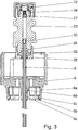
- the Figure 4 shows an inventive design of the second seal
- the Figures 5 to 9 show different alternatives of a second seal (30).
- the holder (6) and hollow piston (9) are only shown in their lower part (a complete representation of these components can be found in the Figures 1 to 3 ).
- Figure 4 shows an example of the second seal (30) which is attached as an additional sealing component on the outside of a tube such as the hollow piston (9) or on the holder (6) forming the container receptacle on the device.
- a radial is shown here symmetrical seal (30), which in the upper area of the insertion funnel (31a), ie in its widened area above the press fit to the hollow piston (9), Seals the container cap (31) and hollow piston (9) against each other.
- this second seal (30) encloses the hollow piston (9) radially in the area of the holder (6) - either directly or at a distance from the inner guide (6d).
- the upper side of the seal (30) bears on the holder (6), in particular on the inner guide (6d), which is pulled down a little along the hollow piston (9) towards the container (3).
- the seal (30) designed as a component has a circular cylindrical recess on the inside for the passage of the hollow piston (9), a funnel-shaped shape in the upper area which is adapted to the shape of the inner guide (6d) of the holder (6), and an outside in this example conical shape tapering towards the container (3).
- This conical shape forms a counterpart to the inner contour of the insertion funnel (31a) of the container cap (31).
- the seal (30) dips from the holder (6) with the hollow piston (9) into the conical opening which the container (3) or the container cap (31) has for the introduction of the hollow piston (9).
- the second seal (30) seals in the conical wall area of the insertion funnel (31a) of the container cap (31).
- the seal (30) is preferably preassembled surrounding the hollow piston (9) on the holder (6), wherein it is supported by the inner guide (6d). If the container (3) is now inserted into the atomizer (1) and pushed axially onto the hollow piston (9), the seal (30) between the inner guide (6d) and the inner wall of the insertion funnel (31a) on the container cap ( 31) axially pressed. If one considers the connection of the container (3) to the device as a whole, a sealing effect is achieved both by axial pressing, in particular parallel to the tubular component or hollow piston (9), and by radial pressing, in particular perpendicular to Hollow piston (9) achieved.
- the combination of a radially acting seal in the form of an interference fit between the hollow piston (9) and the container cap (31) and the essentially axially acting additional seal (30) between the container cap (31) and the container receptacle results in a double-acting sealing of the system.
- the seal (30) preferably consists of an elastomer such as silicon and / or carbon based elastomeric polymers.
- Suitable materials include natural and synthetic elastomers, for example nitrile rubber, butadiene rubber, styrene-butadiene rubber, isoprene rubber, styrene-isoprene copolymers, butyl rubber such as isobutene-isoprene rubber, polyurethane, fluorine rubber, siloxanes such as in particular Silicones and dienes such as in particular EPDM (ethylene-propylene-diene rubber) or another elastomer suitable for use in the medical field.
- the seal can be additionally coated.
- sealing components made of fluorine rubber coated with PTFE are advantageous against the background of better separability on assembly machines for mass production.
- PTFE polytetrafluoroethylene
- the use of a soft elastomer, in particular one with a Shore hardness in the range from 40 to 70 Shore, for the seal (30) has the advantage that both the insertion funnel (31a) and the hollow piston (9) have a hard Soft seal is formed. Unevenness in the comparatively hard surfaces of the insertion funnel (31a) and hollow piston (9) can thus be compensated for by the seal (30), so that the transition area between the components is also sealed for volatile substances.
- the seal (30) can thus also be used as a gas phase seal are referred to, since here the permeation of gases along the hollow piston (9) is prevented.
- the seal (30) shown has the additional advantage that it projects far into the insertion funnel (31a) and thus the dead volume, ie the unused free space between the second seal (30), hollow piston (9) and first seal (press fit between hollow piston ( 9) and the container cap (31)) is kept comparatively small. This dead volume is constant as long as the container (3) is installed in the device. The components involved in the seal are not moved against each other during operation of the device or atomizer (1).
- the material of the seal (30) corresponds to that in the exemplary embodiment Figure 4 .
- a material should be selected for the special application that is in particular diffusion-tight to the substances contained in the medical formulation, that is to say, for example, does not permit gas permeation of the solvent.
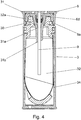
- This in Figure 5 Shown component forming the seal (30) is also radially symmetrical and has the shape of a cup or cap opened at the bottom. The opening of the cup is the passage of the hollow piston (9).
- the inner shape of the sealing component or the inner contour of the cup is the counterpart to the shape of the inner guide (6d) of the holder (6) in the region of the hollow piston (9).
- the sealing component has an upper circular-cylindrical area which merges into an area that tapers conically downwards.
- the cup bottom is funnel-shaped. Sealing takes place by means of a purely radial pressing of the seal (30) between the inner guide (6a) of the holder (6) and a circular cylindrical opening area (31c) of the container cap (31). This circular cylindrical opening area (31c) adjoins the insertion funnel (31a) upwards on the container cap (31).
- both seals are between by radial pressing Container (3) or container cap (31) and hollow piston (9) or holder (6) are formed.
- the radial effect of the seal (30) has the advantage that no additional axial forces have to be applied when the container (3) is inserted into the device.
- the component that forms the second seal (30) is shaped here in such a way that it has a support region that lies in the axial direction on another component of the device, in particular on the holder (6).
- the cap-like or cup-like shape of the sealing component is matched to the lower edge of the inner guide (6d) of the holder (6) and the inner cup bottom, which represents the supporting area of the sealing component, lies against the inner guide (6d) at the bottom.
- the support area of the component forming the seal (30) thus lies on the area of the holder (6) protruding into the container (3).
- the sealing component is held in position by this support and does not slide into the upper axial space when the container (3) is docked, ie when the container (3) is inserted into the holder (6) between the container cap (31) and holder (6).
- the non-sealing, supported lower area of the sealing component can be widened.
- This lower region of the component forming the seal (30) preferably has no direct wall contact with the insertion funnel (31a) of the container cap (31), so that no additional axial forces act when the container (3) is docked.
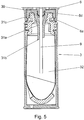
- Figure 6 and 7 show two further seal (30) in the installed state, which form alternatives to the seal according to the invention.
- the seal acts radially between the inner guide (6d) of the holder (6) and the inner wall the container cap (31), or specifically in the cylindrical opening area (31c) above the insertion funnel (31a). Due to the radial effect of the seal (30), no significant additional axial forces have to be applied when the container (3) is inserted into the device.
- the seal is a hard-soft seal on both sides, in which the surface-soft material of the seal (30) compensates for the surface unevenness of the container cap or the inner guide (6d) of the holder (6) in the sealing area.
- the seal (30) can have the shape of a flat ring seal, which is put over the inner guide (6d) of the holder (6) ( Figure 6 ), or it can have the form of a flat or O-ring-shaped seal (30) embedded in the inner guide (6d) ( Figure 7 ), which is held in position by a radial recess on the inner guide (6d).
- the inner guide itself can taper downwards, and the seal (30) - adapted to the shape of the inner guide - can be a ring widened downwards and inwards, which is supported inwards on the inner guide (6d) (not in the figures) variant shown).
- a preferred assembly method for both the seal (30) according to the embodiment Figure 4 as well as for seals according to the examples Figure 5 to 7 is as follows: First, the hollow piston (9) is firmly connected to the holder (6), preferably by injection molding the plastic material of the holder (6) directly onto the hollow piston (9) in an insert injection molding process. Then the holder (6) with the hollow piston (9) is attached in the container-side (ie here below) open but otherwise completely assembled atomizer (1). Before or preferably after the mounting of the holder (6) in the atomizer (1), the radially symmetrical component forming the seal (30) of Centered at the bottom along the hollow piston (9) and pushed into its position on the holder (6) or on the inner guide (6d).
- This process is preferably carried out without contact not to cause any damage to the hollow piston, such as grooves or other bumps, which can weaken the effectiveness of the first seal, in the example shown the seal due to the press fit between the hollow piston (9) and the container cap (31).
- a material with an elongation at break of at least 200%, preferably with an elongation at break between 300% and 500% is selected for the seal (30).
- the material must also be selected so that the component undergoes a purely elastic deformation under this load and then returns to its original shape.
- the component forming the seal (30) is preferably mounted by means of a device in which at least three gripping arms protrude into the circular passage of the component and spread it out from the inside.
- the expanded component is pushed over the hollow piston (9) into its position on the holder (6).
- a plastic sleeve lying inside between the grippers can also serve to protect the hollow piston.
- an outer sleeve is pushed forward, which pushes the component downwards when the gripper arms are pulled back.
- the position of the component forming the seal (30) can also be further fine-tuned when the container (3) is docked onto the atomizer (1) if the container cap (31) , Seal (30) and bracket (6) axially together if necessary be pushed.
- the component forming the seal (30) in the preassembled atomizer (1) it can be closed before delivery either with a lower housing part (18) without a container or preferably with a partially docked container (3) and lower housing part (18) to a pre-installed one System to be completed.
- Figure 8 shows as a fourth alternative to the seal according to the invention a seal (30) in which the sealing effect is achieved by the fit of the holder (6) and the container cap (31).
- the holder (6) or its inner guide (6d) is shaped in such a way that it forms the seal (30) itself by being placed directly on the container cap (31). This is particularly advantageous with regard to production costs and assembly processes, since the seal (30) can be formed without the installation of an additional component.
- the holder (6) surrounds the hollow piston (9) along a central section and is permanently connected to it, in particular by injection molding.
- the inner guide (6d) resting on the hollow piston is significantly narrower in all exemplary embodiments compared to the entire diameter of the holder (6) and projects into the holder (6) after the container (3) has been connected to it.
- this second seal (30) is a hard-hard seal, because due to the requirement for retention properties, in particular the holder (6) and the container cap (31), both components must have a certain rigidity.
- the inner guide (6d) is designed in such a way that it rests on the container cap (31) in the upper opening area.
- the inner guide (6d) can also lie directly in the upper region of the insertion funnel (31a). In this case, it preferably forms a circumferential, pointed edge which, for better sealing, presses into the surface of the insertion funnel (31a), that is to say into the slope that tapers inwards.
- This edge is preferably not only tapering in the radial direction but also in the axial direction, ie the outer lower edge of the inner guide (6d) projects further in the direction of the container (3) than the material contact between the inner guide (6d) and the hollow piston formed by extrusion coating (9).
- the inner guide (6d) thus has an undercut in this example, not shown.
- These seals (30) formed by the inner guide (6d) preferably act axially, so that they have the same effect as in the example shown Figure 4 form a suitable combination for the radially acting, sealing press fit between the hollow piston (9) and the container cap (31).
- Figure 9 shows as a fifth alternative to the seal according to the invention a second seal (30) in the installed state, in which the seal (30) as an independent component the top of the container is inserted or inserted into the holder (6).
- the seal (30) is in the form of a radially symmetrical flat seal, preferably a flat ring seal, which is optionally provided with internal lead-in chamfers.
- the material of the seal (30) corresponds to that in the exemplary embodiment Figure 4 .
- the seal (30) acts primarily axially (parallel to the tube or hollow piston (9)) due to its pressing, thus forming a suitable combination for a radially acting, sealing press fit between the hollow piston (9) and the container cap (31).
- the second seal can also be formed by a sealing layer - an area additionally molded onto the holder (6), the material of which differs from that of the holder (6).
- This additional material area can consist of an elastomeric material and fill similar areas on the holder (6) as the independent elastomeric components in the embodiment according to Figure 4 and the alternative examples in Figure 5 to 7 and 9 .
- the material is softer than that of the container cap and holder.
- This sealing layer can be formed from one of the abovementioned elastomer materials, but in particular from a thermoplastic elastomer (TPE), such as, for example, based on urethane or olefins.
- TPE thermoplastic elastomer
- the sealing points and the effect of the seal correspond to those of the embodiment in FIG Figure 4 or the examples from Figure 9 and Figure 5 to 7 . So there has been talk in the examples shown so far of a seal (30) which is "attached" to the device, so In addition to the individual components mounted on the device, this expression also includes sealing layers that are integrally connected to other device components.
- the sealing layer can also be an area additionally molded onto the container (3) or onto the container cap (31) from one of the elastomeric materials mentioned.
- the sealing layer is located either on the inner edge of the insertion point or on the inner wall of the insertion funnel (31a) or in the upper region of the container cap (31).
- the sealing layer can be designed, for example, as one or more molded-on tabs which protrude upwards before the container (3) is inserted into the holder (6) and then, when inserting the contours of the holder (6), into the space between the container cap (31 ) and inner guide (6d) is pressed.
- Such a sealing layer attached to the container cap (31) has the advantage in particular in the case of reusable devices - for example in an atomizer (1) which is operated in succession with a plurality of containers (3) - that each seal (30) is used only once and can therefore experience no previous damage.
- Each container (3) brings a new, unused sealing system from the first and second seal into the device.
- the holder (6) has an additional material area which is harder than the material of the container cap (31).
- this additional material area is an insert in multi-component injection molding.
- This insert preferably made of a hard metal, could axially better in the material of the at the lower end of the inner guide (6d) Press the container cap (31) into the insertion funnel (31a) or - in the case of a single pairing of device and container - cut into the plastic chosen for the encapsulation of the hollow piston (9) for the holder (6), which has a certain elasticity with regard to The quality of the snap hooks (6a) must have.
- the propellant-free atomizer shown here serves to dispense a liquid medical formulation as an inhalable aerosol and is suitable for dispensing both aqueous and preferably alcoholic, in particular ethanolic, medical formulations.
- a liquid medical formulation to be administered is used which contains a substance with high vapor pressure or an alcoholic compound.
- Preferred ingredients of the preferably liquid medical formulation are in particular in the writings WO09 / 047173A2 and WO09 / 115200A1 listed.
- the fluid described in these documents can be aqueous or non-aqueous solutions, mixtures, formulations with and without solvents, such as ethanol or the like.
- the proposal to equip the junction of a container with a liquid dispensing device with a double seal against liquid and gas loss is applicable to many devices in which liquids are conveyed or transported.
- the invention is applicable to all types of Dosing pullers aimed at devices from which a predefined amount of liquid is drawn from a container with each withdrawal.
- the proposed atomizer (1) works mechanically, while the sealing system presented here is not limited to use in purely mechanical devices for dispensing a liquid.
- the liquid is applied by electrical, hydraulic or other pumps or by propellants. Terms such as “pressure generators" are therefore to be understood generally. In this sense, the present invention can also be used across territories; even applications beyond the medical field are possible.
Description
Die vorliegende Erfindung betrifft Geräte zum Verabreichen von flüssigen, medizinischen Formulierungen, die fluidische Verbindung dieser Geräte mit beispielsweise treibgasfreien Behältern, welche die jeweilige Flüssigkeit enthalten, und die Abdichtung der Behälter und der fluidischen Verbindung zwischen Behälter und Gerät nach außen. Insbesondere bezieht sich die Erfindung auf kleinere portable Geräte wie beispielsweise von Hand betriebene Zerstäuber oder Injektoren, wie sie für die Inhalation oder Injektion von flüssigen Arzneimittelformulierungen verwendet werden.The present invention relates to devices for administering liquid, medical formulations, the fluid connection of these devices with, for example, propellant-free containers which contain the respective liquid, and the sealing of the containers and the fluidic connection between the container and the device to the outside. In particular, the invention relates to smaller portable devices such as, for example, hand-operated atomizers or injectors, such as are used for the inhalation or injection of liquid pharmaceutical formulations.
Aus dem Stand der Technik ist eine Vielzahl an medizinischen Geräten und Zerstäubern bekannt, die mit einer Flüssigkeit betrieben werden. Bei den meisten ist die Flüssigkeit in Vorratsgefäßen oder Behältern abgefüllt, die mehrere Einheiten der Flüssigkeit zur Verabreichung mit dem Gerät enthalten. Zur Entnahme der Flüssigkeit bzw. der Einheiten in Form von abgemessenen Teilmengen aus dem Behälter wird eine fluidische Verbindung zwischen Gerät und Behälter hergestellt, je nach Anwendung dauerhaft oder unterbrechbar. Die fluidische Verbindung wird entweder durch Entnahmeleitungen wie Kanülen oder Schläuche, die in den Behälter eingeführt werden, oder durch das Freilegen von Öffnungen im Behälter und deren Anschluss an zugehörige Kanäle im Geräteinnern hergestellt. Zu letztere Gruppe zählen auch Systeme wie beispielsweise die Treibgas-enthaltenden Metered Dose Inhaler (MDIs), in denen eine Vorkammer oder Dosierkammer in den Behälter integriert ist und über einen Umschaltmechanismus - z.B. in Form eines beweglichen Stößels mit entsprechenden Durchführungen - die Vorkammer entweder mit dem Flüssigkeitsvorrat oder mit dem Gerät verbunden wird.
Allen diesen Systemen gemeinsam ist die Notwendigkeit, die Verbindungsstelle zwischen Behälter und Gerät - sei sie nun statisch oder dynamisch bewegt - nach außen hin abzudichten, so dass keine Flüssigkeit aus dem System außer über den vorgesehenen Ausbringungsweg entweicht.
Die Forderungen an die Abdichtung der Verbindung zwischen Gerät und Behälter hängen insbesondere bei Handgeräten wie Zerstäubern von der zu verabreichenden Arzneimittelformulierung und ihrer Konzentration, dem verwendeten Lösemittel, oder von klimatischen Bedingungen am Einsatzort ab und können somit stark variieren. Die Schnittstelle von Behälter zu Gerät muss gegen alle Substanzen aus der Arzneimittelformulierung dicht und materialbeständig sein. Die Formulierung kann nicht nur flüssige und feste sondern auch gasförmige Bestandteile enthalten, wobei Gasdichtigkeit in der Regel eine höhere Forderung als Flüssigkeitsdichtigkeit darstellt. Einige Arzneimittelformulierungen enthalten leicht flüchtige Substanzen wie beispielsweise das oft als Lösemittel eingesetzte Ethanol. Beim separaten Entweichen einer flüchtigen Substanz aus dem Behälter kann sich die Konzentration der Formulierung ändern. Je nach Zusammensetzung der Formulierung kann dadurch die Konzentration eines Wirkstoffs in der Lösung erhöht werden oder ein gelöster Stoff kann auskristallisieren. Solche Substanzen entweichen in erster Linie in gasförmiger Form: Diese Substanzen, die von Natur aus einen erhöhten Dampfdruck haben, wechseln insbesondere bei klimatischen Veränderungen auch innerhalb des Behälters schnell teilweise in die Gasphase über. Unter Umständen können bereits kleine Temperaturerhöhungen oder Drucksenkungen in der Umgebung des Behälters zu einer verstärkten Gasbildung im Behälter führen, und dieses Gas kann teilweise durch eine in erster Linie auf Flüssigkeitsdichtigkeit ausgelegte Dichtung entweichen.A large number of medical devices and atomizers which are operated with a liquid are known from the prior art. Most of the liquid is filled into storage jars or containers that contain multiple units of the liquid for administration with the device. To remove the liquid or the units in the form of measured portions from the container, a fluidic connection between the device and the container is established, depending on the application, permanently or interruptibly. The fluidic connection is established either through sampling lines such as cannulas or hoses that are inserted into the container, or by exposing openings in the container and connecting them to associated channels inside the device. The latter group also includes systems such as the Metered Dose Inhaler (MDIs) containing propellant gas, in which a prechamber or dosing chamber is integrated in the container and via a switching mechanism - for example in the form of a movable plunger with corresponding bushings - the antechamber is connected either to the liquid supply or to the device.
Common to all these systems is the need to seal the connection point between the container and the device - be it statically or dynamically moved - to the outside, so that no liquid escapes from the system except through the intended delivery path.
The requirements for the sealing of the connection between the device and the container depend, in particular in the case of hand-held devices such as atomizers, on the pharmaceutical formulation to be administered and their concentration, the solvent used or on climatic conditions at the place of use and can therefore vary widely. The interface from container to device must be tight and resistant to all substances from the pharmaceutical formulation. The formulation can contain not only liquid and solid but also gaseous constituents, gas tightness generally being a higher requirement than liquid tightness. Some pharmaceutical formulations contain volatile substances such as ethanol, which is often used as a solvent. If a volatile substance escapes from the container separately, the concentration of the formulation can change. Depending on the composition of the formulation, the concentration of an active ingredient in the solution can be increased or a dissolved substance can crystallize out. Such substances primarily escape in gaseous form: These substances, which naturally have an increased vapor pressure, quickly change partially into the gas phase, particularly in the event of climatic changes, even within the container. Under certain circumstances, even small ones Temperature increases or pressure drops in the vicinity of the container lead to increased gas formation in the container, and this gas can escape in part through a seal designed primarily for liquid tightness.
Ein mechanischer, miniaturisierter Hochdruckzerstäuber, mit dem flüssige Arzneimittelformulierungen zur Inhalation aus einem mehrere Einheiten der Formulierung enthaltenden Behälter zerstäubt werden und in dessen Inneren der Fluidweg statisch und dynamisch abgedichtet ist, ist aus der
In der
In der
Der vorliegenden Erfindung liegt die Aufgabe zugrunde, ein gegenüber dem Stand der Technik verbessertes Gerät - insbesondere ein Handgerät wie einen Zerstäuber oder Injektor - zum Verabreichen von medizinischen Formulierungen aus einem Behälter anzugeben, bei dem die Verbindungsstelle von Behälter und Gerät entsprechend der verwendeten Formulierung flüssigkeitsdicht und gasdicht abgedichtet ist. Insbesondere soll das Dichtsystem keine Permeabilität gegenüber den flüssigen und gasförmigen Substanzen der Formulierung aufweisen bzw. es soll keine Diffusionsleckagen zulassen, insbesondere wenn die Formulierungen Substanzen mit hohem Dampfdruck wie z.B. Ethanol enthalten. Das Gerät mit Dichtsystem an der Verbindungsstelle von Behälter und Gerät soll insbesondere für das Bereitstellen von abgemessenen Flüssigkeitsmengen geeignet sein. Die mit diesen Dichtsystemen ausgestatteten Geräte sollen hierbei möglichst unabhängig von der späteren Verwendung, d.h. insbesondere unabhängig von klimatischen Bedingungen und insbesondere unabhängig von klimatischen Schwankungen oder von der jeweiligen für den Anwender unter Umständen individuell festgelegten Benutzung oder Therapie sein. Je nach Therapie kann die pro Gerät vorgesehene Anzahl an Betätigungen pro Tag abhängig von Wirkstoffformulierung und Dosierung von Gerät zu Gerät variieren. Des weiteren soll das Gerät mit Dichtsystem für die Massenfertigung geeignet sein. Insbesondere soll das Dichtsystem hinsichtlich Anzahl und Art seiner Bauteile möglichst preisgünstig sein und es soll zuverlässig ohne Beschädigungen in Massenfertigung montierbar sein.The present invention has for its object to provide a device improved over the prior art - in particular a hand-held device such as an atomizer or injector - for administering medical formulations from a container, in which the connection point between the container and the device in accordance with the formulation used is liquid-tight and is sealed gas-tight. In particular, the sealing system should not have any permeability to the liquid and gaseous substances of the formulation or should not allow diffusion leakages, especially if the formulations contain substances with high vapor pressure, such as ethanol. The device with the sealing system at the junction of the container and the device should be particularly suitable for the provision of measured quantities of liquid. The devices equipped with these sealing systems should be as independent as possible of the later use, ie in particular independent of climatic conditions and in particular independent of climatic fluctuations or of the particular use or therapy that may be individually defined for the user. Depending on the therapy, the number of operations per device per day can vary from device to device depending on the active ingredient formulation and dosage. Furthermore, the device with sealing system should be suitable for mass production. In particular, the sealing system should be as inexpensive as possible with regard to the number and type of its components and it should be able to be assembled reliably in mass production without damage.
Die genannte Aufgabe wird erfindungsgemäß gelöst durch ein Gerät zum Verabreichen einer flüssigen medizinischen Formulierung, die sich in einem in das Gerät eingesetzten Behälter befindet. Der Behälter ist innerhalb des Geräts auf ein steifes Rohr aufgeschoben ist, das mit einer Halterung verbunden ist, die den Behälter im Gerät aufnimmt, zum Beispiel durch Einklemmen. Der Behälter weist eine Einführstelle auf, an der eine erste Dichtung in Form einer Passdichtung zwischen Behälter und einem Abschnitt des steifen Rohres vorliegt, das der Flüssigkeitsentnahme aus dem Behälter dient. Zwischen der Halterung und dem Behälter ist eine zweite Dichtung vorhanden, die den Raum zwischen der ersten Dichtung, dem Behälter und dem Rohr gegen den Austritt von Flüssigkeit und Gasen und/oder gegen das Eindringen von Gasen abdichtet.
Die zweite Dichtung dichtet die fluidische Verbindung zwischen Gerät und Behälter gegenüber der Umgebung zusätzlich ab. Durch die beiden aufeinander folgenden Dichtungen wird das nicht gewollte Austreten von Flüssigkeit und Gas aus dem Behälter und/oder das Eindringen von Gas in den Behälter besser verhindert als durch die erste Dichtung allein.According to the invention, this object is achieved by a device for administering a liquid medical formulation, which is located in a container inserted into the device. The container is pushed onto a rigid tube inside the device, which is connected to a holder which receives the container in the device, for example by being pinched. The container has an insertion point at which there is a first seal in the form of a mating seal between the container and a section of the rigid tube which is used to remove liquid from the container. Between the holder and the container there is a second seal which seals the space between the first seal, the container and the pipe against the escape of liquid and gases and / or against the penetration of gases.
The second seal additionally seals the fluidic connection between the device and the container from the environment. The two successive seals prevent the unwanted escape of liquid and gas from the container and / or the penetration of gas into the container better than the first seal alone.
Vorteilhafte Weiterbildungen werden im Folgenden und im Detail anhand der Figuren beschrieben.Advantageous further developments are described below and in detail with reference to the figures.
Ein Merkmal der vorliegenden Erfindung ist, dass die erste Dichtung im wesentlichen dicht gegenüber den flüssigen Bestandteilen der medizinischen Formulierung im Behälter und die zweite Dichtung im wesentlichen dicht gegenüber Gasen ist. Hierdurch werden die Forderungen an die Dichtigkeit des Systems insgesamt in unterschiedliche Forderungen an zwei voneinander separate Dichtungen aufgeteilt. Das bietet den Vorteil, dass die einzelnen Forderungen gezielt erfüllt werden können, ohne unter dem Zwang zu stehen, eine einzige u.U. teure oder technisch aufwendige oder hinsichtlich von Teilaspekten mangelhafte Lösung zu benutzen. Auf diese Weise kann beispielsweise eine erste behälterseitige Dichtung in erster Linie auf die Rückhaltung der im Behälter befindlichen Flüssigkeit unter voller Berücksichtigung der Forderungen an die Materialverträglichkeiten von Flüssigkeit und Dichtungsmaterial ausgelegt sein. Die Forderung der Gasdichtigkeit der fluidischen Verbindung des Geräts mit dem Behälter kann mittels der zweiten Dichtung gezielt gelöst werden. Dies bedeutet u.a., dass für diese zweite Dichtung, die auch als Gasphasendichtung bezeichnet werden kann, beispielsweise das Material in erster Linie unter dem Aspekt der Gasdurchlässigkeit gewählt werden kann, ohne dass die hierbei verwendeten Materialien zwangsläufig chemisch verträglich zur Flüssigkeit im Behälter sein müssen. Dies ist insbesondere relevant für Systeme, in denen der Behälter leicht flüchtige Substanzen wie beispielsweise Ethanol enthält. Leicht flüchtige Substanzen zeigen sowohl aufgrund ihres Dampfdrucks eine hohe Diffusion durch feinste Kanäle, als auch bei andauerndem fluidischen Kontakt eine signifikante Diffusion durch eine Vielzahl von Kunststoffmaterialien.A feature of the present invention is that the first seal is substantially sealed to the liquid components of the medical formulation in the container and the second seal is substantially sealed to gases. This will make the Requirements for the tightness of the system as a whole are divided into different requirements for two separate seals. This offers the advantage that the individual requirements can be met in a targeted manner without being forced to use a single, possibly expensive, or technically complex solution, or one that is defective in terms of partial aspects. In this way, for example, a first seal on the container side can be designed primarily to retain the liquid in the container while taking full account of the requirements for the material compatibility of the liquid and sealing material. The requirement of the gas tightness of the fluid connection of the device with the container can be specifically solved by means of the second seal. This means, inter alia, that for this second seal, which can also be referred to as a gas phase seal, for example the material can be selected primarily from the aspect of gas permeability, without the materials used here necessarily having to be chemically compatible with the liquid in the container. This is particularly relevant for systems in which the container contains volatile substances such as ethanol. Volatile substances show high diffusion through the finest channels due to their vapor pressure, as well as significant diffusion through a large number of plastic materials in the event of permanent fluid contact.
Ein weiteres Merkmal der vorliegenden Erfindung ist, dass während die erste Dichtung durch eine Passdichtung oder Presspassung zwischen dem Behälter - bevorzugt einem Teilbereich eines in eine Behälterkappe integriertem Einführtrichter - und dem der Flüssigkeitsentnahme dienendem Rohr gebildet wird, die zweite Dichtung durch nur ein zusätzliches Bauteil oder eine zusätzliche Dichtungsschicht zwischen dem Behälter bzw. der Behälterkappe und der Halterung des Behälters im Gerät gebildet wird. Die Dichtungsschicht, deren Material vorzugsweise weicher als das von Behälterkappe und Halterung ist, kann z.B. durch Anspritzen entweder auf der dem Behälter zugewandten Seite der Halterung oder am Innenrand der Einführstelle am Behälter bzw. im oberen Bereich der Behälterkappe angebracht sein. Insbesondere wirken beide Dichtungen - erste und zweite - durch direkten Kontakt zur Behälterkappe.
Eine durch ein zusätzliches Bauteil gebildete Dichtung wird vorzugsweise am Gerät angebracht. Sie besteht aus nur einem elastomeren Bauteil, das beim Andocken des Behälters zwischen Behälterkappe und Gerät verpresst wird. Diese geräteseitige Dichtung kann eine kappenartige oder becherartige oder hülsenartige oder konusartige Form mit Durchlassöffnung für das Rohr aufweisen oder eine O-Ring-Dichtung, Flachdichtung oder Ringdichtung sein.
Alternativ zum Einsatz einer elastomeren Dichtung können beide Dichtungen durch den direkten Kontakt von Behälterkappe zu harten Bauteilen des Geräts gebildet werden. Insbesondere können durch Presspassungen zwischen der Behälterkappe und dem steifen, der fluidischen Verbindung zwischen Behälter und Gerät dienenden Rohr einerseits und einer die Behälteraufnahme bildenden Halterung am Gerät andererseits gebildet werden.
Durch eine solche Maßnahme wird eine zusätzliche Abdichtung der Verbindungsstelle von Behälter zu Gerät mit keinem oder nur einem zusätzlichen Bauteil erzielt. Dieses Dichtsystem ist kostengünstig und für die Massenfertigung geeignet. Die doppelte Abdichtung hat zusätzlich den Vorteil, dass sich gelegentliche Undichtigkeiten nicht auf die Dichtigkeit des Systems insgesamt auswirken können. Derartige Undichtigkeiten können durch sporadisch auftretende Unebenheiten auf einer zu dem Dichtungssystem gehörenden harten Oberfläche, wie beispielsweise der Oberfläche des Rohrs im Bereich der Presspassung mit der Behälterkappe, verursacht werden, Eine zweite Dichtung fängt eine eventuelle Leckage an der Stelle der ersten auf. Hierdurch können unter Umständen Forderungen an Produktionsprozess und ggf. Produktionskosten gesenkt werden.A further feature of the present invention is that while the first seal is formed by a mating seal or press fit between the container - preferably a partial area of an insertion funnel integrated in a container cap - and the tube serving for the removal of liquid, the second seal is formed by only one additional component or an additional sealing layer is formed between the container or the container cap and the holder of the container in the device. The sealing layer, the material of which is preferably softer than that of the container cap and holder, can be applied, for example, by injection molding either on the side of the holder facing the container or on the inner edge of the insertion point on the container or in the upper region of the container cap. In particular, both seals - first and second - work through direct contact with the container cap.
A seal formed by an additional component is preferably attached to the device. It consists of only one elastomeric component, which is pressed between the container cap and the device when the container is docked. This device-side seal can have a cap-like or cup-like or sleeve-like or cone-like shape with a passage opening for the tube or an O-ring seal, flat seal or ring seal.
As an alternative to using an elastomeric seal, both seals can be formed by direct contact between the container cap and hard components of the device. In particular, press fits between the container cap and the rigid tube serving for the fluidic connection between container and device on the one hand and a holder on the device forming the container receptacle on the other hand can be used.
Such a measure provides additional sealing of the connection point from container to device with no or only one additional component. This sealing system is inexpensive and suitable for mass production. The double seal has the additional advantage that occasional leaks cannot affect the overall tightness of the system. Such leaks can be caused by sporadically occurring bumps on a hard surface belonging to the sealing system, such as, for example, the surface of the pipe in the area of the press fit with the container cap. A second seal catches any leakage at the location of the first. Under certain circumstances, this can reduce demands on the production process and possibly production costs.
Bei den hier dargestellten Geräten zum Verabreichen von medizinischen Formulierungen werden bevorzugt Handgeräte wie Zerstäuber oder Injektoren betrachtet, mit denen Flüssigkeiten in vorbestimmten Volumina oder definierten Mengen zerstäubt oder eingespritzt werden.
Der Begriff "Flüssigkeit" umfasst neben reinen Flüssigkeiten und Lösungen zusätzlich Dispersionen, Suspensionen, Suslutionen (Mischungen aus Lösungen und Suspensionen) oder dergleichen. Unter dem Begriff "medizinische Formulierung" oder "Arzneimittelformulierung" sind bei der vorliegenden Erfindung über Medikamente hinaus auch Therapeutica oder dergleichen, insbesondere also jede Art von Mitteln zur Inhalation oder sonstigen Anwendung bei Mensch und Tier zu verstehen.In the devices for administering medical formulations shown here, preference is given to using handheld devices such as atomizers or injectors, with which liquids are atomized or injected in predetermined volumes or defined amounts.
In addition to pure liquids and solutions, the term "liquid" also includes dispersions, suspensions, suspensions (mixtures of solutions and suspensions) or the like. In the present invention, the term “medical formulation” or “pharmaceutical formulation” also means therapeutic agents or the like in addition to medicaments, in particular any kind of means for inhalation or other use in humans and animals.
Die einzelnen Merkmale der vorliegenden Erfindung können unabhängig voneinander genutzt oder miteinander kombiniert werden.
Weitere Vorteile, Merkmale, Eigenschaften und Aspekte der vorliegenden Erfindung ergeben sich aus der folgenden Beschreibung bevorzugter Ausführungsformen anhand der Zeichnungen. Die Zeichnungen zeigen in:
- Fig. 1
- einen schematischen Längsschnitt eines Zerstäubers im "ungespannten" Zustand,
- Fig. 2
- einen schematischen, um 90° gegenüber
Fig.1 gedrehten Längsschnitt des Zerstäubers ausFig. 1 im "gespannten" Zustand, - Fig. 3
- einen schematischen Längsschnitt durch die Zerstäuber-Bauteile Düse, Filter, Pumpenkammer, Hohlkolben und Halterung für den nicht dargestellten Behälter.
- Fig. 4
- einen schematischen Längsschnitt durch die Anbindungsstelle eines Behälters an eine Förderpumpe mit einer erfindungsgemäßen Abdichtung
- Fig. 5
- einen schematischen Längsschnitt durch die Anbindungsstelle eines Behälters an eine Förderpumpe gemäß einer ersten Alternative zur erfindungsgemäßen Abdichtung
- Fig. 6
- einen schematischen Längsschnitt durch die Anbindungsstelle eines Behälters an eine Förderpumpe gemäß einer zweiten Alternative zur erfindungsgemäßen Abdichtung
- Fig. 7
- einen schematischen Längsschnitt durch die Anbindungsstelle eines Behälters an eine Förderpumpe gemäß einer dritten Alternative zur erfindungsgemäßen Abdichtung
- Fig. 8
- einen schematischen Längsschnitt durch die Anbindungsstelle eines Behälters an eine Förderpumpe gemäß einer vierten Alternative zur erfindungsgemäßen Abdichtung
- Fig. 9
- einen schematischen Längsschnitt durch die Anbindungsstelle eines Behälters an eine Förderpumpe gemäß einer fünften Alternative zur erfindungsgemäßen Abdichtung
Further advantages, features, properties and aspects of the present invention result from the following description of preferred embodiments with reference to the drawings. The drawings show in:
- Fig. 1
- 2 shows a schematic longitudinal section of an atomizer in the "untensioned" state,
- Fig. 2
- a schematic, 90 ° opposite
Fig. 1 turned longitudinal section of the atomizerFig. 1 in the "tense" state, - Fig. 3
- a schematic longitudinal section through the atomizer components nozzle, filter, pump chamber, hollow piston and holder for the container, not shown.
- Fig. 4
- a schematic longitudinal section through the connection point of a container to a feed pump with a seal according to the invention
- Fig. 5
- a schematic longitudinal section through the connection point of a container to a feed pump according to a first alternative to the seal according to the invention
- Fig. 6
- a schematic longitudinal section through the connection point of a container to a feed pump according to a second alternative to the seal according to the invention
- Fig. 7
- a schematic longitudinal section through the connection point of a container to a feed pump according to a third alternative to the seal according to the invention
- Fig. 8
- a schematic longitudinal section through the connection point of a container to a feed pump according to a fourth alternative to the seal according to the invention
- Fig. 9
- a schematic longitudinal section through the connection point of a container to a feed pump according to a fifth alternative to the seal according to the invention
In den Figuren werden für gleiche oder ähnliche Teile dieselben Bezugszeichen verwendet, wobei entsprechende oder vergleichbare Eigenschaften und Vorteile erreicht werden, auch aus
Beim Betrieb des Zerstäubers wird unterschieden zwischen dem so genannten "ungespannten" Zustand mit unbefülltem Dosiervolumen in der Druckkammer (11) (
Beim so genannten "Spannen" des Zerstäubers (1) wird sein Gehäuseoberteil (16) relativ zum Gehäuseinnenteil (17) und Gehäuseunterteil (18) um einen festen Drehwinkel z.B. 180° gedreht. Mittels eines innen angeordneten Schraub-Schub-Getriebes wird durch die Relativdrehung eine Kolbenpumpe angetrieben, so dass eine vorbestimmte, ggf. einstellbare Menge der Flüssigkeit (2) aus dem Behälter (3) in die Druckkammer gefördert und gleichzeitig die auf den Hohlkolben (9) wirkende Antriebsfeder (7) gespannt wird. Der Endzustand des Spannvorgangs ist in
When operating the atomizer, a distinction is made between the so-called "untensioned" state with unfilled metering volume in the pressure chamber (11) (
During the so-called "tensioning" of the atomizer (1), its upper housing part (16) is rotated relative to the inner housing part (17) and lower housing part (18) by a fixed angle of rotation, for example 180 °. A piston pump is driven by the relative rotation by means of an internally arranged screw-thrust gear, so that a predetermined, possibly adjustable amount of the liquid (2) is conveyed from the container (3) into the pressure chamber and at the same time the quantity on the hollow piston (9) acting drive spring (7) is tensioned. The The final state of the clamping process is in
Im Flüssigkeitsauslassbereich der Druckkammer (11) befindet sich ein Filtersystem (27, 28), das in Flussrichtung vor der vorzugsweise mikrostrukturierten Düse (12) liegt und diese gegen die Ablagerung von Partikeln schützt. Über die Kombination verschiedenartiger Filter (27, 28) und Filtertechniken wird eine hohe Abscheidung erzielt. Im Falle des Ausführungsbeispiels wird die Düse (12) bevorzugt von einem mikrostrukturierten Bauteil aus einem Glas-Silizium-Verbund gebildet, das selbst bereits einen als Strömungsfilter ausgelegten Feinstfilter vor den eigentlichen Düsenkanälen enthält. Die Zerstäubung der Flüssigkeit durch diese Düsenkanäle beruht vorzugsweise auf der Impaktion von zwei mikroskopischen Flüssigkeitsstrahlen mit hoher Geschwindigkeit aus nur wenigen Mikrometern durchmessenden Düsenkanälen.
A filter system (27, 28) is located in the liquid outlet area of the pressure chamber (11) and is located in the direction of flow in front of the preferably microstructured nozzle (12) and protects it against the deposition of particles. A high level of separation is achieved by combining different types of filters (27, 28) and filter techniques. In the case of the exemplary embodiment, the nozzle (12) is preferably formed by a microstructured component made of a glass-silicon composite which itself already contains a fine filter designed as a flow filter in front of the actual nozzle channels. The atomization of the liquid through these nozzle channels is preferably based on the impaction of two microscopic liquid jets at high speed from nozzle channels with a diameter of only a few micrometers.
Das Zentralteil (23) bildet die seitliche Begrenzung der Druckkammer (11), den Flüssigkeitseinlass in Form der Durchführung für den Flüssigkeits-führenden Hohlkolben (9), den Einbauraum für die gegen den Hohlkolben (9) abdichtende Dichtung (24) und die fluidische Anbindung zur Düsenbaugruppe (29), welche die Düse (12) und diverse zugehörige Halterungs- oder Dichtungsbauteile enthält. In der gezeigten Ausführungsform mit kreiszylindrischer Druckkammer (11) nimmt das Zentralteil (23) in einer zentralen Bohrung ein oder mehrere Filterbauteile im Anschluss an die Druckkammer (11) auf. Im Beispiel sind die Filterbauteile ein Vorfilter (27), vorzugsweise aus einem Kunststoff, und ein Feinfilter (28), vorzugsweise aus Metall. Weiter stromabwärts schließt sich das beschriebene mikrostrukturierte Bauteil an, das Feinstfilter und Düsenkanäle enthält.The central part (23) forms the lateral boundary of the pressure chamber (11), the liquid inlet in the form of the passage for the liquid-carrying hollow piston (9), the installation space for the seal (24) sealing against the hollow piston (9) and the fluidic connection to the nozzle assembly (29), which contains the nozzle (12) and various associated mounting or sealing components. In the embodiment shown with a circular cylindrical pressure chamber (11), the central part (23) accommodates one or more filter components in a central bore following the pressure chamber (11). In the example, the filter components are a prefilter (27), preferably made of a plastic, and a fine filter (28), preferably made of metal. Further downstream is the microstructured component described, which contains fine filters and nozzle channels.
Im Darstellungsbeispiel weist der Zerstäuber (1) bzw. sein Druckerzeuger (5) eine Halterung (6) für den Behälter (3) auf. Diese Halterung (6) ist unlösbar mit dem Hohlkolben (9) verbunden - vorzugsweise angespritzt, beispielsweise auch verklebt oder verschnappt. Beim axialen Spannen der Antriebsfeder (7) wird die Halterung (6) mit dem Behälter (3) und dem Hohlkolben (9) bei den Darstellungen nach unten bewegt. Der Behälter (3) wird über die Halterung (6) insbesondere klemmend oder rastend so in dem Zerstäuber (1) fixiert, dass der Hohlkolben (9) in den Fluidraum des Behälters (3) eintaucht und/oder fluidisch mit der Flüssigkeit (2) im Behälter (3) verbunden wird und die Flüssigkeit über den Hohlkolben angesaugt wird. Hohlkolben (9) und Behälter (3) werden somit beim Betrieb des Zerstäubers (1) nach Verbindung des Behälters (3) mit der Halterung (6) nicht mehr zueinander bewegt, d.h. nach Andocken des Behälters (3) an das Gerät gibt es keine Relativbewegung der an der Abdichtung der Verbindungsstelle von Gerät zu Behälter beteiligten Bauteile zueinander. Die Dichtungen zwischen Gerät und Behälter (3) bzw. Behälterkappe (31) sind somit statisch. Dies hat den Vorteil, dass das Dichtsystem, durch die der Flüssigkeitsvorrat selbst vor Leckagen und Diffusion geschützt wird, keinerlei Reibungsbeanspruchung unterliegt und es somit nicht zum Verschleiß der Dichtungen kommen kann. Vorzugsweise bilden Behälter (3) und Halterung (6) eine Steckverbindung, bei der insbesondere mehrere Schnapphaken (6a) der Halterung (6) in eine umlaufende Kontur im oberen Bereich des Behälters (3) eingreifen. Diese Kontur kann beispielsweise eine umlaufende Rille oder wie im Ausführungsbeispiel der untere Kragenrand einer den Behälter (3) verschließenden Behälterkappe (31) sein. In den hier gezeigten Ausführungsformen weist die Halterung 4 bis 12, vorzugsweise 6 oder 12 Schnapphaken oder Rippen auf. Wird der Behälter (3) mit seiner Behälterkappe (31) voran entlang des Hohlkolbens (9) in die Halterung (6) geschoben, so trifft die Behälterkappe (31) zuerst auf die Einführschrägen (6b) an den Schnapphaken (6a). Durch die nach innen geneigten Einführschrägen (6b) werden die Schnapphaken (6a) durch die Behälterkappe (31) nach außen gespreizt, bis die Behälterkappe (31) an den nach innen gerichteten Wülsten (6c) der Schnapphaken (6a) vorbei gleiten kann. Sobald die untere Außenkante der Behälterkappe (31) die Wülste (6c) passiert hat, federn die Schnapphaken (6a) wieder nach innen zurück, so dass die Wülste (6c) den Behälter (3) am unteren Rand der Behälterkappe (31) festhalten. Die Halterung (6) kann bei Bedarf derart ausgebildet sein, dass der Behälter (3) ausgetauscht werden kann. Diese Austauschbarkeit wird über die Federeigenschaften der Schnapphaken (6a) erreicht. Länge, Breite und vor allem Dicke und Material der Halterung (6) werden entsprechend gewählt. Die Halterung (6) besteht vorzugsweise aus einem Kunststoff aus der Gruppe der Thermoplaste wie beispielsweise PPO (Polyphenylenoxid) bzw. PPE (Polyphenylenether) oder PBT (Polybutylenterephthalat). Die Geometrie der Wülste (6c) und der Anteil der Wülste (6c) am inneren Umfangskreis der Halterung (6) werden angepasst. Zur Feineinstellung der notwendigen Kräfte zum Einsetzen oder Entnehmen des Behälters (3) in die oder aus der Halterung (6) ist es zweckdienlich, nur einen Teil der Rippen an der Halterung mit Wülsten (6c) zur Bildung von Schnapphaken (6a) auszustatten. So weist z.B. die Halterung (6) der in
Die Austauschbarkeit des Behälters wird nicht nur durch die Eigenschaften der Halterung (6) sondern auch durch seine Zugänglichkeit bestimmt: Im Darstellungsbeispiel aus
Alternativ zum Darstellungsbeispiel kann der Zerstäuber (1) auch so gestaltet sein, dass der Behälter (3) im Zerstäuber vorinstalliert ist. Bei dieser - hier nicht anhand der Figuren dargestellten - Variante mit voreingesetztem Behälter (3) wird dieser bereits ab Werk in den Zerstäuber (1) oder in ein zusätzliches Halte- oder Sicherungselement im Gehäuseunterteil (18) eingesetzt, das bei Auslieferung nur teilweise auf das Gehäuseinnenteil (17) aufgeschoben ist. Beim weiteren Aufschieben auf das Gehäuseinnenteil (17) gleitet das Gehäuseunterteils (18) beispielsweise über eine nur in eine Bewegungsrichtung gleitend gestaltete Ratschenbahn oder hakt nach vollständigem Aufschieben in eine variable gestaltbare Verrastung unlösbar ein. Gleichzeitig wird beim Aufschieben des Gehäuseunterteils der Behälter (3) in seine Halterung (6) geschoben und an den Hohlkolben (9) angeschlossen. Weitere Details zur Gestaltung solcher Systeme mit voreingesetztem Behälter (3) können der
As an alternative to the example shown, the atomizer (1) can also be designed such that the container (3) is pre-installed in the atomizer. In this variant - not shown here with the aid of the figures - with a pre-inserted container (3), this is already inserted ex works in the atomizer (1) or in an additional holding or securing element in the lower housing part (18), which is only partially relied upon upon delivery Inner housing part (17) is pushed on. When it is pushed further onto the inner housing part (17), the lower housing part (18) slides, for example, over a ratchet track which is only designed to slide in one direction of movement or, after being completely pushed on, hooks into a variable, configurable latching device. At the same time, when the lower part of the housing is pushed on, the container (3) is pushed into its holder (6) and connected to the hollow piston (9). Further details on the design of such systems with a pre-installed container (3) can be found in the
Vorzugsweise sind die hier betrachteten medizinischen Handgeräte auf die Ausbringung mehrerer Dosiseinheiten der flüssigen, medizinischen Formulierung ausgelegt. So zeigt der Zerstäuber (1) in
Für die hier gewählten Darstellungsbeispiele, entsprechend denen auch in den
For the display examples selected here, corresponding to those in the
Entweicht Lösemittel über die Gasphase, bleibt weniger Lösemittel für die medizinische Formulierung im Behälter (3) zurück, und der Wirkstoff wird in der Flüssigkeit (2) aufkonzentriert. Durch diese Aufkonzentration würde beim Entnehmen einer abgemessenen Menge Flüssigkeit (2) eine relativ erhöhte Dosis des Wirkstoffes entnommen. Somit ist dieser Verlust von Lösemittel durch die Gasphase zu begrenzen oder nach Möglichkeit vermeiden. Dies ist eine der Forderungen an die Gestaltung des Behälters (3), die Wahl der verwendeten Materialien und die Gestaltung der Abdichtungen beim Einsetzen des Behälters (3) in das jeweilige Gerät bzw. in den Zerstäuber (1). Vorzugsweise wird für den die Flüssigkeit (2) aufnehmenden Beutel (32) als flexibles Wandmaterial eine mehrschichtig aufgebaute Folie oder dergleichen verwendet. Die Folie umfasst eine mit der medizinischen Flüssigkeit kompatible Kunststoffschicht und eine Metallschicht wie z.B. eine Aluminiumschicht oder ähnliches. Dadurch wird die Diffusion oder Permeation von Gas durch die Beutelwand hindurch minimiert.
Der für die Darstellungsbeispiele gewählte Behälter (3) umfasst einen inneren Beutel (32), einen Flansch (32a), eine Behälterkappe (31) und eine starre Hülse (34). Der flexible, mehrschichtige, unten geschlossene Beutel (32) ist im oberen Bereich direkt mit einem Halt gebenden Flansch (32a) vorzugsweise aus Kunststoff verbunden. Die starre Hülse (34) umgibt den Beutel (32) und schützt ihn vor mechanischen Beschädigungen von außen. Die Behälterkappe (31) ist vorzugsweise aus Kunststoff, besonders bevorzugt aus HD-PE, und insbesondere aus einem ähnlichen oder dem gleichen Material wie der Flansch (32a). Die Behälterkappe (31) wird nach Befüllen des Beutels (32) mit Flüssigkeit (2) vorzugsweise über einen Warmverformungsprozess oder einen Schweißprozess (z.B. Ultraschall- oder Laserschweißen) dicht mit dem Flansch (32a) verbunden.If solvent escapes via the gas phase, less solvent remains for the medical formulation in the container (3) and the active ingredient is concentrated in the liquid (2). This concentration would remove a relatively increased dose of the active ingredient when a measured amount of liquid (2) was removed. This loss of solvent through the gas phase must therefore be limited or avoided if possible. This is one of the requirements for the design of the container (3), the choice of materials used and the design of the seals when inserting the container (3) into the respective device or into the atomizer (1). A multilayer film or the like is preferably used as the flexible wall material for the bag (32) holding the liquid (2). The film comprises a plastic layer compatible with the medical fluid and a metal layer such as an aluminum layer or the like. This minimizes the diffusion or permeation of gas through the bag wall.
The container (3) selected for the illustration examples comprises an inner bag (32), a flange (32a), a container cap (31) and a rigid sleeve (34). The flexible, multilayer, closed bag (32) is connected in the upper area directly to a retaining flange (32a), preferably made of plastic. The rigid sleeve (34) surrounds the bag (32) and protects it from mechanical damage from the outside. The container cap (31) is preferably made of plastic, particularly preferably made of HD-PE, and in particular of a similar or the same material as the flange (32a). After the bag (32) has been filled with liquid (2), the container cap (31) is preferably tightly connected to the flange (32a) by means of a hot forming process or a welding process (for example ultrasound or laser welding).
Die Behälterkappe (31) weist als Einführstelle einen in den Innenraum des Beutels (32) hineinragenden Einführtrichter (31a) auf, der bei Anschluss des Behälters an den Zerstäuber (1) eine zentrierte Führung für den Hohlkolben (9) bildet und somit ein bezogen auf die Verbindungsstelle unkontrolliertes Anstechen des Behälters (3) durch den Hohlkolben (9) verhindert. Vor der Anbindung an den Zerstäuber (1) ist der Behälter bzw. das dem Innenraum des Behälters (3) zugewandte Ende des Einführtrichters (31a) mit einer Membran (31b) verschlossen, die beim Einführen des Hohlkolbens (9) durchstochen oder aufgeklappt wird. Auf diese Weise schützt die Membran (31b) den nichtangestochenen Behälter vor Flüssigkeitsaustritt. Zusätzlich besteht die hier nicht in den Figuren dargestellte Möglichkeit, den Behälter während der Lagerung mit einem Kopfsiegel zu versehen, das beispielsweise aus einer Metallfolie vorzugsweise aus Aluminium bestehen kann und das obere offene Ende des Einführtrichters (31a) verschließt. Ein solches Siegel kann als Originalitätszeichen dienen und den Einführtrichter (31a) während des Transportes von einzelnen Kartuschen vor Verunreinigungen schützen. Gase, welche die Membran (31b) gegebenenfalls durchdringen können, werden von einem metallischen Kopfsiegel zurückgehalten. Vor Einbau des Behälters (3) in das Gerät kann das Kopfsiegel entfernt werden, z.B. durch Abziehen mittels einer überstehenden Lasche.
Nach kompletter Einführung des Behälters (3) in die Halterung (6) des Zerstäubers (1) liegt eine Presspassung zwischen dem eingeführten Rohr oder Hohlkolben (9) und der Wand der Einführtrichters (31a) vor. Diese Presspassung in einem Abschnitt des Einführtrichters (31a) bildet eine zur Behälterkappe (31) gehörende Dichtung, die hier auch als erste Dichtung bezeichnet wird. Die radial wirkende Presspassung dichtet die Kontaktstelle zwischen Hohlkolben (9) und dem Inneren des Behälters (3) gegen Flüssigkeitsverlust außen am Hohlkolben (9) vorbei über eine Länge von 1 bis 10 Millimetern, vorzugsweise 2 bis 7 Millimeter, besonders bevorzugt 5 mm ab. Im Darstellungsbeispiel ist der Hohlkolben (9) aus Metall, vorzugsweise aus Edelstahl. Die Behälterkappe (31) ist aus einem gegenüber dem Hohlkolben (9) weicheren KunststoffMaterial, vorzugsweise PE oder HD-PE. Das Material der Behälterkappe (31) darf jedoch nicht beliebig weich sein, da für die Funktionssicherheit des Systems Formstabilität wichtig ist. Aus diesem Grund kann die Presspassung zwischen Hohlkolben (9) und Einführtrichter (31a) zwar gegen Flüssigkeitsdurchlass dicht ausgelegt werden, nicht jedoch zwangsläufig auch gegen Gasdurchlässigkeit. Je nach Fertigungsverfahren des Hohlkolbens (9) können sich beispielsweise bis hin zu wenigen Mikrometer tiefen Riefen oder Unebenheiten auf seiner Oberfläche befinden, welche die Gaspermeation durch die Presspassung hindurch begünstigen. Aus diesem Grund ist hier eine zweite Dichtung (30) mit gegenüber der Presspassung veränderten Dichteigenschaften eingebaut, um entweder durch die Presspassung entweichendes Gas abzufangen oder im Vorfeld bereits Luft am Eindringen in das System von außen am Hohlkolben (9) vorbei zu hindern. Die
Vorzugsweise ist die Dichtung (30) den Hohlkolben (9) umgebend auf der Halterung (6) vormontiert, wobei sie durch die Innenführung (6d) abgestützt wird. Wird nun der Behälter (3) in den Zerstäuber (1) eingesetzt und dabei axial auf den Hohlkoben (9) aufgeschoben, so wird die Dichtung (30) zwischen Innenführung (6d) und der inneren Wand des Einführtrichters (31a) an der Behälterkappe (31) axial verpresst. Betrachtet man die Anbindung des Behälters (3) an das Gerät insgesamt, so wird eine Dichtungswirkung sowohl durch axiale Verpressung insbesondere parallel zum rohrförmigen Bauteil oder Hohlkolben (9) als auch durch radiale Verpressung insbesondere senkrecht zum Hohlkolben (9) erzielt. Durch die Kombination einer radial wirkenden Dichtung in Form der Presspassung zwischen Hohlkolben (9) und Behälterkappe (31) und der im wesentlichen axial wirkenden zusätzlichen Dichtung (30) zwischen Behälterkappe (31) und Behälteraufnahme wird eine doppelt wirkende Abdichtung des Systems erzielt. Die Dichtung (30) besteht vorzugsweise aus einem Elastomer wie Silizium- und/oder Kohlenstoff basierten elastomeren Polymeren. Geeignete Materialien umfassen natürliche und synthetische Elastomere, beispielsweise Nitril-Kautschuk, Butadien-Kautschuk, Styrol-Butadien-Kautschuk, Isopren-Kautschuk, Styrol-Isopren-Kopolymere, ButylKautschuk wie Isobuten-Isopren-Kautschuk, Polyurethan, Fluor-Kautschuk, Siloxane wie insbesondere Silikone und Diene wie insbesondere EPDM (Ethylen-Propylen-DienKautschuk) oder einem anderen für die Verwendung im medizinischen Bereich geeigneten Elastomer. Je nach Forderung, z.B. bei geforderten speziellen Materialresistenzen oder montagebedingten Gleiteigenschaften, kann die Dichtung zusätzlich beschichtet sein. So sind z.B. mit PTFE (Polytetrafluorethylen) beschichtete dichtende Bauteile aus Fluor-Kautschuk vor dem Hintergrund einer besseren Vereinzelbarkeit auf Montagemaschinen für die Massenfertigung vorteilhaft.
Die Verwendung eines weichen Elastomers, insbesondere eines mit einer Shore-Härte im Bereich von 40 bis 70 Shore, für die Dichtung (30) hat den Vorteil, dass sowohl gegenüber dem Einführtrichter (31a) als auch gegenüber dem Hohlkolben (9) eine Hart-Weich-Dichtung ausgebildet wird. Unebenheiten in den vergleichsweise harten Oberflächen von Einführtrichter (31a) und Hohlkolben (9) können somit von der Dichtung (30) ausgeglichen werden, so dass der Übergangsbereich zwischen den Bauteilen auch für flüchtige Substanzen dicht ist. Die Dichtung (30) kann somit auch als Gasphasendichtung bezeichnet werden, da hier die Permeation von Gasen am Hohlkolben (9) entlang unterbunden wird.
Die im speziellen Ausführungsbeispiel aus
Ein bevorzugtes Montageverfahren sowohl für die Dichtung (30) gemäß der Ausführungsform aus
Zunächst wird der Hohlkolben (9) fest mit der Halterung (6) verbunden, vorzugsweise indem das Kunststoffmaterial der Halterung (6) direkt in einem Einlege-Spritzgussverfahren an den Hohlkolben (9) angespritzt wird. Dann wird die Halterung (6) mit dem Hohlkolben (9) im behälterseitig (d.h. hier unten) offenen, aber ansonsten fertig montierten Zerstäuber (1) angebracht. Vor oder bevorzugt nach der Montage der Halterung (6) im Zerstäuber (1) wird das die Dichtung (30) bildende, radialsymmetrische Bauteil von unten zentriert am Hohlkolben (9) entlang in seine Position an der Halterung (6) bzw. an der Innenführung (6d) geschoben. Dieser Vorgang erfolgt bevorzugt berührungsfrei, um keine Beschädigungen am Hohlkolben wie beispielsweise Riefen oder andere Unebenheiten zu erzeugen, welche die Wirksamkeit der ersten Dichtung, im Darstellungsbeispiel die Dichtung durch die Presspassung zwischen Hohlkolben (9) und Behälterkappe (31), schwächen können.
Für eine berührungsfreie Montage wird für die Dichtung (30) ein Material mit Reißdehnung von mindestens 200%, bevorzugt mit einer Reißdehnung zwischen 300% und 500% gewählt. In diesem Zusammenhang bedeutet dies, dass das radialsymmetrische Bauteil hinsichtlich seines Durchmessers um mindestens das Doppelte, bevorzugt das dreibis fünffache ausgeweitet werden kann, ohne dass sich Risse bilden. Das Material muss darüber hinaus so gewählt sein, dass das Bauteil bei dieser Belastung eine rein elastische Verformung durchläuft und anschließend wieder in seine Ursprungsform zurückkehrt. Die Montage des die Dichtung (30) bildenden Bauteils erfolgt vorzugsweise mittels eines Vorrichtung, bei der mindestens drei Greifarme in die kreisförmige Durchführung des Bauteils hineinragen und dieses von innen nach außen aufspreizen. Das aufgespreizte Bauteil wird über den Hohlkolben (9) in seine Position an der Halterung (6) geschoben. Eine innen zwischen den Greifern liegende Kunststoffhülse kann hierbei zusätzlich dem Schutz des Hohlkolbens dienen. Sobald das die Dichtung (30) bildende Bauteil seine axiale Position an Hohlkolben (9) bzw. Halterung (6) erreicht hat, wird eine äußere Hülse vorgeschoben, die das Bauteil beim Zurückziehen der Greifarme von diesen herunter schiebt. Je nach Form der des dichtenden Bauteils bzw. je nach Vorhandensein eines Abstützbereichs, kann eine weitere Feinjustierung der Position des die Dichtung (30) bildenden Bauteils auch beim Andocken des Behälters (3) an den Zerstäuber (1) erfolgen, wenn Behälterkappe (31), Dichtung (30) und Halterung (6) ggf. axial weiter zusammen geschoben werden. Nach Montage des die Dichtung (30) bildenden Bauteils im vormontierten Zerstäuber (1), kann dieser vor Auslieferung wahlweise mit einem Gehäuseunterteil (18) ohne Behälter verschlossen oder vorzugsweise mit einem nur teilweise angedockten Behälters (3) und Gehäuseunterteil (18) zu einem vorinstallierten System vervollständigt werden.The container cap (31) has an insertion funnel (31a) protruding into the interior of the bag (32), which forms a centered guide for the hollow piston (9) when the container is connected to the atomizer (1) and is thus related to the connection point prevents uncontrolled piercing of the container (3) by the hollow piston (9). Before the connection to the atomizer (1), the container or the end of the insertion funnel (31a) facing the interior of the container (3) is closed with a membrane (31b) which is pierced or opened when the hollow piston (9) is inserted. In this way, the membrane (31b) protects the non-pierced container from liquid leakage. In addition, there is the possibility, not shown here in the figures, of providing the container with a head seal during storage which, for example, can consist of a metal foil, preferably of aluminum, and closes the upper open end of the insertion funnel (31a). Such a seal can serve as a tamper-evident symbol and protect the insertion funnel (31a) from contamination during the transport of individual cartridges. Gases that can penetrate the membrane (31b) are retained by a metallic head seal. Before installing the container (3) in the device, the head seal can be removed, for example by pulling it off with a protruding tab.
After complete insertion of the container (3) into the holder (6) of the atomizer (1), there is an interference fit between the inserted tube or hollow piston (9) and the wall of the insertion funnel (31a). This press fit in a section of the insertion funnel (31a) forms a seal belonging to the container cap (31), which is also referred to here as the first seal. The radially acting press fit seals the contact point between the hollow piston (9) and the interior of the container (3) Loss of liquid on the outside past the hollow piston (9) over a length of 1 to 10 millimeters, preferably 2 to 7 millimeters, particularly preferably 5 mm. In the example shown, the hollow piston (9) is made of metal, preferably stainless steel. The container cap (31) is made of a plastic material that is softer than the hollow piston (9), preferably PE or HD-PE. However, the material of the container cap (31) must not be as soft as desired, since dimensional stability is important for the functional reliability of the system. For this reason, the interference fit between the hollow piston (9) and the insertion funnel (31a) can be designed to be tight against liquid passage, but not necessarily against gas permeability. Depending on the manufacturing process of the hollow piston (9), there may be grooves or bumps on its surface down to a few micrometers deep, which promote gas permeation through the press fit. For this reason, a second seal (30) with modified sealing properties compared to the press fit is installed in order to either trap gas escaping through the press fit or to prevent air from entering the system from the outside past the hollow piston (9). The
The seal (30) is preferably preassembled surrounding the hollow piston (9) on the holder (6), wherein it is supported by the inner guide (6d). If the container (3) is now inserted into the atomizer (1) and pushed axially onto the hollow piston (9), the seal (30) between the inner guide (6d) and the inner wall of the insertion funnel (31a) on the container cap ( 31) axially pressed. If one considers the connection of the container (3) to the device as a whole, a sealing effect is achieved both by axial pressing, in particular parallel to the tubular component or hollow piston (9), and by radial pressing, in particular perpendicular to Hollow piston (9) achieved. The combination of a radially acting seal in the form of an interference fit between the hollow piston (9) and the container cap (31) and the essentially axially acting additional seal (30) between the container cap (31) and the container receptacle results in a double-acting sealing of the system. The seal (30) preferably consists of an elastomer such as silicon and / or carbon based elastomeric polymers. Suitable materials include natural and synthetic elastomers, for example nitrile rubber, butadiene rubber, styrene-butadiene rubber, isoprene rubber, styrene-isoprene copolymers, butyl rubber such as isobutene-isoprene rubber, polyurethane, fluorine rubber, siloxanes such as in particular Silicones and dienes such as in particular EPDM (ethylene-propylene-diene rubber) or another elastomer suitable for use in the medical field. Depending on the requirement, for example in the case of required special material resistance or sliding properties due to assembly, the seal can be additionally coated. For example, sealing components made of fluorine rubber coated with PTFE (polytetrafluoroethylene) are advantageous against the background of better separability on assembly machines for mass production.
The use of a soft elastomer, in particular one with a Shore hardness in the range from 40 to 70 Shore, for the seal (30) has the advantage that both the insertion funnel (31a) and the hollow piston (9) have a hard Soft seal is formed. Unevenness in the comparatively hard surfaces of the insertion funnel (31a) and hollow piston (9) can thus be compensated for by the seal (30), so that the transition area between the components is also sealed for volatile substances. The seal (30) can thus also be used as a gas phase seal are referred to, since here the permeation of gases along the hollow piston (9) is prevented.
Which in the specific embodiment
A preferred assembly method for both the seal (30) according to the embodiment
First, the hollow piston (9) is firmly connected to the holder (6), preferably by injection molding the plastic material of the holder (6) directly onto the hollow piston (9) in an insert injection molding process. Then the holder (6) with the hollow piston (9) is attached in the container-side (ie here below) open but otherwise completely assembled atomizer (1). Before or preferably after the mounting of the holder (6) in the atomizer (1), the radially symmetrical component forming the seal (30) of Centered at the bottom along the hollow piston (9) and pushed into its position on the holder (6) or on the inner guide (6d). This process is preferably carried out without contact not to cause any damage to the hollow piston, such as grooves or other bumps, which can weaken the effectiveness of the first seal, in the example shown the seal due to the press fit between the hollow piston (9) and the container cap (31).
For contact-free assembly, a material with an elongation at break of at least 200%, preferably with an elongation at break between 300% and 500%, is selected for the seal (30). In this context, this means that the diameter of the radially symmetrical component can be expanded by at least twice, preferably three to five times, without cracks forming. The material must also be selected so that the component undergoes a purely elastic deformation under this load and then returns to its original shape. The component forming the seal (30) is preferably mounted by means of a device in which at least three gripping arms protrude into the circular passage of the component and spread it out from the inside. The expanded component is pushed over the hollow piston (9) into its position on the holder (6). A plastic sleeve lying inside between the grippers can also serve to protect the hollow piston. As soon as the component forming the seal (30) has reached its axial position on the hollow piston (9) or holder (6), an outer sleeve is pushed forward, which pushes the component downwards when the gripper arms are pulled back. Depending on the shape of the sealing component or depending on the presence of a support area, the position of the component forming the seal (30) can also be further fine-tuned when the container (3) is docked onto the atomizer (1) if the container cap (31) , Seal (30) and bracket (6) axially together if necessary be pushed. After assembly of the component forming the seal (30) in the preassembled atomizer (1), it can be closed before delivery either with a lower housing part (18) without a container or preferably with a partially docked container (3) and lower housing part (18) to a pre-installed one System to be completed.
Je nach Wahl der Materialien der in
Depending on the choice of materials in
Alternativ zu den in den Figuren gezeigten Beispielen kann die zweite Dichtung auch durch eine Dichtungsschicht gebildet werden - einen an die Halterung (6) zusätzlich angespritzten Bereich, dessen Material sich von dem der Halterung (6) unterscheidet. Dieser zusätzliche Materialbereich kann aus einem elastomeren Material bestehen und ähnliche Bereiche an der Halterung (6) ausfüllen wie die eigenständigen elastomeren Bauteile in der Ausführungsform gemäß
As an alternative to the examples shown in the figures, the second seal can also be formed by a sealing layer - an area additionally molded onto the holder (6), the material of which differs from that of the holder (6). This additional material area can consist of an elastomeric material and fill similar areas on the holder (6) as the independent elastomeric components in the embodiment according to
In einem weiteren, nicht gezeigten Alternativsbeispiel, in dem die zweite Dichtung (30) ähnlich wie Darstellungsbeispiel von
Der hier dargestellte treibgasfreie Zerstäuber dient der Ausgabe einer flüssigen medizinischen Formulierung als inhalierfähiges Aerosol und eignet sich für die Ausbringung sowohl wässriger als auch bevorzugt alkoholischer, insbesondere ethanolischer, medizinischer Formulierungen. Insbesondere wird hier eine zu verabreichende flüssige medizinische Formulierung eingesetzt, die eine Substanz mit hohem Dampfdruck oder eine alkoholische Verbindung enthält.The propellant-free atomizer shown here serves to dispense a liquid medical formulation as an inhalable aerosol and is suitable for dispensing both aqueous and preferably alcoholic, in particular ethanolic, medical formulations. In particular, a liquid medical formulation to be administered is used which contains a substance with high vapor pressure or an alcoholic compound.
Bevorzugte Inhaltsstoffe der vorzugsweise flüssigen medizinischen Formulierung sind insbesondere in den Schriften
Insbesondere kann es sich bei dem in diesen Schriften beschriebenen Fluid um wässrige oder nicht wässrige Lösungen, Mischungen, Formulierungen mit und ohne Lösungsmittel, wie Ethanol oder dergleichen, handeln.In particular, the fluid described in these documents can be aqueous or non-aqueous solutions, mixtures, formulations with and without solvents, such as ethanol or the like.
Der Vorschlag, die Verbindungsstelle eines Behälters mit einem der Ausbringung von Flüssigkeit dienenden Gerät mit einer doppelten Dichtung gegen Flüssigkeits- und Gasverlust auszustatten, ist auf viele Geräte, in denen Flüssigkeiten gefördert oder transportiert werden, übertragbar. Insbesondere ist die Erfindung auf alle Arten von Dosierziehern gerichtet, d.h. auf Geräte, aus denen mit jeder Entnahme eine vordefinierte Menge an Flüssigkeit aus einem Behälter gezogen wird. Des Weiteren arbeitet der vorschlagsgemäße Zerstäuber (1) mechanisch, während das hier vorgestellte Dichtsystem nicht auf die Anwendung in rein mechanischen Geräten zur Ausbringung einer Flüssigkeit begrenzt ist. Es kann beispielsweise ebenso in Systemen eingesetzt werden, in denen die Flüssigkeit durch elektrische, hydraulische oder andere Pumpen oder durch Treibmittel ausgebracht wird. Begriffe wie "Druckerzeuger" sind also allgemein zu verstehen. In diesem Sinne kann die vorliegende Erfindung auch Gebiets-übergreifend verwendet werden; selbst Anwendungen über den medizinischen Bereich hinaus sind möglich.
Claims (15)
- Device for administering a liquid medicinal formulation which is located in a container (3) inserted in the device, wherein the container inside the device is pushed onto a rigid tube and this tube is connected to the holder (6) for the container (3) in the device, and wherein the container (3) has an insertion point, which is located on the container (3) on a container cap (31) belonging to the latter and at which a first seal in the form of a fitting seal is provided between the container (3) and a portion of the rigid tube, wherein the first seal is formed between the container cap (31) and the rigid tube and the insertion point on the container (3) is configured as an insertion funnel (31a), wherein this insertion funnel (31a) has a conical opening region,
characterised
in that between the holder (6) and the container (3) is a second seal (30) which seals off a space between the first seal, the container (3) and the tube to prevent the escape of liquids and gases and/or to prevent the ingress of gases, wherein the second seal (30) is formed by an additional component or by a sealing layer and this component or this sealing layer is located between the holder (6) and the container cap (31), and
in that the second seal (30) seals in the conical wall region of the insertion funnel (31a). - Device according to claim 1 characterised in that the first seal is substantially leaktight against the liquid components of the medicinal formulation in the container (3) and the second seal (30) is substantially leaktight against gases.
- Device according to claim 1 or 2, characterised in that the second seal (30) is formed by an elastomeric component which is arranged between the holder (6) and the container cap (31) and is compressed as the container (3) is docked.
- Device according to claim 1 or 2, characterised in that the second seal (30) is formed by a sealing layer which is located on the side of the holder (6) facing the container (3) and/or which is formed by a region additionally moulded onto the holder (6) or onto an inner guide (6d) belonging to the holder (6), the material of which region is softer than that of the container cap (31).
- Device according to one of claims 1 or 2, characterised in that the second seal is formed by a sealing layer which is formed by a region additionally moulded on in the upper region of the container cap (31), in which the insertion point of the container cap (31) is located, wherein the material of the region additionally moulded on in the upper region of the container cap is softer than the material of the container cap (31).
- Device according to claim 1 or 2, characterised in that the second seal (30) radially surrounds the tube directly or spaced apart from it by an inner guide (6d) on the holder (6).
- Device according to claim 1, 2 or 6, characterised in that the component that forms the second seal (30) or the sealing layer before the insertion of the container (3) in the device or in the holder (6) is mounted at the device end on the tube or on the holder (6) that forms the container receptacle in the device.
- Device according to one of the preceding claims, characterised in that the second seal (30) is axially compressed, particularly parallel to the tube.
- Device according to one of claims 1 to 7, characterised in that the second seal (30) is radially compressed particularly perpendicularly to the tube or perpendicularly to an inner guide (6d) on the holder (6).
- Device according to one of claims 3 or 7, characterised in that the component that forms the second seal (30) has a cap-shaped or cup-shaped or conical shape with a through-opening for the tube.
- Device according to one of claims 3 or 7, characterised in that the component that forms the second seal (30) is an O-ring seal, a flat seal or a ring seal.
- Device according to one of claims 3, 7, 10 or 11, characterised in that the component that forms the second seal (30) is shaped so that it comprises a support region which abuts in the axial direction on the holder (6), particularly on an inner guide (6d) of the holder (6).
- Device according to one of claims 1 to 12, characterised in that the tube the piston is a high pressure pump.
- Device according to one of the preceding claims, characterised in that the liquid medicinal formulation that is to be administered contains a substance with a high vapour pressure or an alcoholic compound.
- Use of the device according to one of the preceding claims, characterised in that the liquid medicinal formulation is administered as an aerosol, particularly an inhalable aerosol, through a nozzle (12) at the device.
Priority Applications (1)
| Application Number | Priority Date | Filing Date | Title |
|---|---|---|---|
| EP12710275.4A EP2694220B1 (en) | 2011-04-01 | 2012-03-23 | Medical device comprising a container |
Applications Claiming Priority (3)
| Application Number | Priority Date | Filing Date | Title |
|---|---|---|---|
| EP11160773 | 2011-04-01 | ||
| PCT/EP2012/055209 WO2012130757A1 (en) | 2011-04-01 | 2012-03-23 | Medical device comprising a container |
| EP12710275.4A EP2694220B1 (en) | 2011-04-01 | 2012-03-23 | Medical device comprising a container |
Publications (2)
| Publication Number | Publication Date |
|---|---|
| EP2694220A1 EP2694220A1 (en) | 2014-02-12 |
| EP2694220B1 true EP2694220B1 (en) | 2020-05-06 |
Family
ID=44558443
Family Applications (1)
| Application Number | Title | Priority Date | Filing Date |
|---|---|---|---|
| EP12710275.4A Active EP2694220B1 (en) | 2011-04-01 | 2012-03-23 | Medical device comprising a container |
Country Status (4)
| Country | Link |
|---|---|
| US (1) | US9757750B2 (en) |
| EP (1) | EP2694220B1 (en) |
| JP (1) | JP6164694B2 (en) |
| WO (1) | WO2012130757A1 (en) |
Families Citing this family (32)
| Publication number | Priority date | Publication date | Assignee | Title |
|---|---|---|---|---|
| EP2077132A1 (en) | 2008-01-02 | 2009-07-08 | Boehringer Ingelheim Pharma GmbH & Co. KG | Dispensing device, storage device and method for dispensing a formulation |
| JP5670421B2 (en) | 2009-03-31 | 2015-02-18 | ベーリンガー インゲルハイム インターナショナル ゲゼルシャフト ミット ベシュレンクテル ハフツング | Component surface coating method |
| US9265910B2 (en) | 2009-05-18 | 2016-02-23 | Boehringer Ingelheim International Gmbh | Adapter, inhalation device, and nebulizer |
| CN102686260B (en) | 2009-11-25 | 2014-10-01 | 贝林格尔.英格海姆国际有限公司 | Nebulizer |
| WO2011064163A1 (en) | 2009-11-25 | 2011-06-03 | Boehringer Ingelheim International Gmbh | Nebulizer |
| US10016568B2 (en) | 2009-11-25 | 2018-07-10 | Boehringer Ingelheim International Gmbh | Nebulizer |
| EP2585151B1 (en) | 2010-06-24 | 2018-04-04 | Boehringer Ingelheim International GmbH | Nebulizer |
| WO2012130757A1 (en) | 2011-04-01 | 2012-10-04 | Boehringer Ingelheim International Gmbh | Medical device comprising a container |
| US9827384B2 (en) | 2011-05-23 | 2017-11-28 | Boehringer Ingelheim International Gmbh | Nebulizer |
| WO2013152894A1 (en) | 2012-04-13 | 2013-10-17 | Boehringer Ingelheim International Gmbh | Atomiser with coding means |
| GR20120100242A (en) * | 2012-05-04 | 2014-01-02 | Micrel Ιατρικα Μηχανηματα Α.Ε., | Analgesia pump/pre-filled bag set |
| EP3030298B1 (en) | 2013-08-09 | 2017-10-11 | Boehringer Ingelheim International GmbH | Nebulizer |
| EP2835146B1 (en) | 2013-08-09 | 2020-09-30 | Boehringer Ingelheim International GmbH | Nebulizer |
| EP3139982B1 (en) | 2014-05-07 | 2022-02-16 | Boehringer Ingelheim International GmbH | Nebulizer |
| KR102443737B1 (en) | 2014-05-07 | 2022-09-19 | 베링거 인겔하임 인터내셔날 게엠베하 | Container, nebulizer and use |
| DK3139984T3 (en) | 2014-05-07 | 2021-07-19 | Boehringer Ingelheim Int | Atomizer |
| US10307550B2 (en) | 2014-06-09 | 2019-06-04 | Dance Biopharm Inc. | Liquid drug cartridges and associated dispenser |
| WO2016096762A1 (en) * | 2014-12-15 | 2016-06-23 | Philip Morris Products S.A. | E-liquid collapsible cartridge |
| FR3032436B1 (en) * | 2015-02-10 | 2019-08-30 | Louis Vuitton Malletier | PACKAGING DEVICE FOR A PRODUCT TO BE DISTRIBUTED |
| CN107690289B (en) * | 2015-06-12 | 2021-04-13 | 菲利普莫里斯生产公司 | Dispensing mechanism |
| US10485939B2 (en) * | 2015-10-01 | 2019-11-26 | Presspart Manufacturing Limited | Metered dose inhaler canister and shroud |
| EP3374011B1 (en) * | 2015-11-09 | 2023-07-19 | Boehringer Ingelheim International GmbH | System comprising nebulizer and container |
| EA038372B1 (en) | 2016-12-21 | 2021-08-17 | Бёрингер Ингельхайм Интернациональ Гмбх | Nebulizer and cartridge |
| DK3697541T3 (en) * | 2017-10-18 | 2023-06-26 | Softhale Nv | SEAL FOR INHALATION DEVICE |
| TWI681787B (en) * | 2017-11-06 | 2020-01-11 | 微邦科技股份有限公司 | Fluid delivery apparatus |
| EP3501582B1 (en) * | 2017-12-21 | 2022-04-27 | Boehringer Ingelheim International GmbH | Nebulizer and cartridge |
| WO2020165623A1 (en) | 2018-09-14 | 2020-08-20 | Olegnovicz Israel | Fluid seal having multiple diameters |
| KR102581567B1 (en) * | 2018-09-27 | 2023-09-26 | 에스에이치엘 메디컬 아게 | Device for aerosol dispenser, aerosol dispenser and method |
| US20210030978A1 (en) * | 2019-07-29 | 2021-02-04 | Cai Gu Huang | Cartridge with single-layer container and its nozzle-shaped cap for nebulization inhalation |
| CA3197126A1 (en) * | 2020-11-04 | 2022-05-12 | Guan Bin LEE | Single-use adapter attached to drug/vaccine vials compatible with hypodermic needles to enable injection |
| GB2602102A (en) * | 2020-12-18 | 2022-06-22 | Merxin Ltd | Micropump having a sealing ring |
| US11772111B1 (en) * | 2022-09-16 | 2023-10-03 | Branded AcquiCo No 5, LLC | Dispenser |
Family Cites Families (574)
| Publication number | Priority date | Publication date | Assignee | Title |
|---|---|---|---|---|
| US1828864A (en) | 1923-02-20 | 1931-10-27 | Gilmont Products Corp | Method of filling bicompartment collapsible tubes |
| GB414953A (en) | 1932-12-24 | 1934-08-16 | Josef Schoene | Medical injection syringe |
| US2127401A (en) | 1937-11-15 | 1938-08-16 | Gillican Charles Crum | Method of packaging rosin |
| US2161071A (en) | 1938-05-02 | 1939-06-06 | Zellerbach Paper Company | Method of packing frozen food |
| US2321428A (en) | 1939-04-25 | 1943-06-08 | Ferdinand G Schloz | Nozzle |
| US2329311A (en) | 1940-06-05 | 1943-09-14 | Harry F Waters | Method of producing liquid-containing packages |
| US2362103A (en) | 1941-01-04 | 1944-11-07 | Arthur E Smith | Ampoule |
| US2651303A (en) | 1948-11-13 | 1953-09-08 | Richard S Johnson | Inhaler |
| US2720969A (en) | 1953-12-10 | 1955-10-18 | Becton Dickinson Co | Package and mounting for hypodermic syringe assembly |
| DK83175C (en) | 1955-07-04 | 1957-07-22 | Grosserer Gorm Tage Hansen | Air control systems for greenhouses. |
| US2974880A (en) | 1955-11-15 | 1961-03-14 | Drackett Co | Aerosol spray head |
| US2793776A (en) | 1956-05-23 | 1957-05-28 | Lipari Michael | Container attachment for providing a compartmental dispensing receptacle |
| US3172568A (en) | 1959-03-27 | 1965-03-09 | Modern Lab Inc | Pressurized dispensing device |
| US3032823A (en) | 1960-05-26 | 1962-05-08 | Sherman Plastics Corp | Method of forming plastic articles |
| GB951228A (en) | 1961-09-26 | 1964-03-04 | Ici Ltd | Packaging process |
| FR1314002A (en) | 1961-11-24 | 1963-01-04 | Method and device for dispensing a non-compacted substance | |
| US3299603A (en) | 1962-03-12 | 1967-01-24 | Continental Can Co | Method of filling pouches |
| NL297349A (en) | 1962-08-31 | |||
| US3354883A (en) | 1965-03-08 | 1967-11-28 | Southerland Elizabeth Lee | Disposable syringe having frangible means for mixing plural medicaments |
| US3440144A (en) | 1965-05-21 | 1969-04-22 | Andersen Prod H W | Method and apparatus for checking and testing the effectiveness of sterilization |
| US3457694A (en) | 1966-08-25 | 1969-07-29 | Hideo Tatibana | Method of and apparatus for fusion sealing the opening of flexible plastic bottle-like containers |
| US3491803A (en) | 1966-10-03 | 1970-01-27 | Haskon Inc | Machine for filling with liquids containers having deformable side walls |
| FR1502925A (en) | 1966-10-12 | 1967-11-24 | Vaporisateurs Marcel Franck | Improvements to piston pumps for dispensing liquids or fluid pastes |
| GB1230472A (en) | 1967-07-10 | 1971-05-05 | ||
| US3590557A (en) | 1968-03-07 | 1971-07-06 | Fr Hesser Maschinenfabrick Ag | Apparatus for closing packaging containers with elastically deformable walls |
| US3580249A (en) | 1968-09-16 | 1971-05-25 | Kentaro Takaoka | Aerosol nebulizers |
| US3674028A (en) | 1969-06-04 | 1972-07-04 | Ims Ltd | Multi-mix |
| US3858580A (en) | 1969-06-04 | 1975-01-07 | Ims Ltd | Intravenous container mixing assembly |
| BE751383R (en) | 1969-08-12 | 1970-12-03 | Oreal | PERFECTIONED VALVE FOR PRESSURIZED CONTAINER DISPENSER OF SEVERAL PRODUCTS |
| US3655096A (en) | 1969-10-22 | 1972-04-11 | Pillsbury Co | Container for diluting and dispensing material |
| US3949751A (en) | 1970-03-03 | 1976-04-13 | Fisons Limited | Method and device for dispensing medicament to the body |
| US3674060A (en) | 1970-12-14 | 1972-07-04 | Continental Can Co | Apparatus for filling and adjusting the contents level in flexible containers |
| BE788194A (en) | 1971-08-31 | 1973-02-28 | Thomae Gmbh Dr K | DEVICE FOR THE ADMINISTRATION OF MECHANICALLY DOSE QUANTITIES OF LIQUID OR SOLUTION MEDICINAL PRODUCTS |
| US3861851A (en) | 1971-12-08 | 1975-01-21 | Schiemann Dr Wolfram | Apparatus for moulding the neck of an extruded hollow body |
| US3802604A (en) | 1972-02-28 | 1974-04-09 | Oreal | Device for storing two products separately and dispensing them simultaneously |
| DE2221101C3 (en) | 1972-04-28 | 1975-05-15 | Wolf-Geraete Gmbh, 5240 Betzdorf | Bottle-like mixing container |
| US3933279A (en) | 1972-11-28 | 1976-01-20 | Ciba-Geigy Corporation | Aerosol dispenser for fluid products comprising a piston pump assembly for generating compressed air |
| US3946732A (en) | 1973-08-08 | 1976-03-30 | Ampoules, Inc. | Two-chamber mixing syringe |
| US3951310A (en) | 1974-02-11 | 1976-04-20 | V.C.A. Corporation | Spring-charged aerosol dispenser |
| US3973603A (en) | 1974-06-18 | 1976-08-10 | Franz Henry H | Control for filling flexible bottles or containers |
| DK140801B (en) | 1975-01-15 | 1979-11-19 | Nordisk Insulinlab | Process for the preparation of a stable long-acting insulin preparation. |
| US3924741A (en) | 1975-03-04 | 1975-12-09 | Gibson Ass Inc | Two-compartment container |
| US3953995A (en) | 1975-05-27 | 1976-05-04 | Haswell John W | Means for making double groove pulleys |
| US4153689A (en) | 1975-06-13 | 1979-05-08 | Takeda Chemical Industries, Ltd. | Stable insulin preparation for nasal administration |
| US4012472A (en) | 1975-07-17 | 1977-03-15 | Arbrook, Inc. | Medical fluids container |
| US4174035A (en) | 1975-09-04 | 1979-11-13 | Georg Wiegner | Two-component container and package |
| US4036439A (en) | 1975-09-24 | 1977-07-19 | Newman-Green, Inc. | Spray head for nebulization of fluids |
| US4067499A (en) | 1976-02-17 | 1978-01-10 | Cohen Milton J | Non-aerosol continuous spray dispenser |
| US4126559A (en) | 1976-03-30 | 1978-11-21 | Pall Corporation | Pharmaceutical filter |
| US4094317A (en) | 1976-06-11 | 1978-06-13 | Wasnich Richard D | Nebulization system |
| US4048997A (en) | 1976-11-01 | 1977-09-20 | Mpl, Inc. | Syringe with actinic radiation protection |
| IT1075249B (en) | 1976-12-10 | 1985-04-22 | Ottina Luigi | TWO-CONTAINER DEVICE FOR THE INDEPENDENT STORAGE OF TWO COMPONENTS AND THE SYSTEMS PREPARATION OF A PRODUCT WITH THESE TWO COMPONENTS |
| US4177938A (en) | 1977-06-30 | 1979-12-11 | Brina Guido J | Container with mixing cartridge |
| US4178928A (en) | 1977-08-10 | 1979-12-18 | Tischlinger Edward A | Self injector |
| US4245788A (en) | 1978-03-20 | 1981-01-20 | Wright Hershel E | Dispensing device for fluid material |
| US4195730A (en) | 1978-06-20 | 1980-04-01 | General Foods Corporation | Container having separate storage facilities for two materials |
| CA1097276A (en) | 1978-12-15 | 1981-03-10 | Marcel J. H. Staar | Package for storing and spraying small amounts of liquids |
| US4315570A (en) | 1979-01-04 | 1982-02-16 | Jules Silver | Two-compartment container with means for dispersing contents of one compartment into the other compartment |
| JPS5819535B2 (en) | 1979-04-16 | 1983-04-19 | 本州製紙株式会社 | How to seal a sealed container |
| EP0018609B1 (en) | 1979-04-30 | 1983-09-21 | Hoechst Aktiengesellschaft | Aqueous solutions of proteins stable against denaturization, process for their manufacture, and their utilization |
| DK374579A (en) | 1979-09-07 | 1981-03-08 | Nordisk Insulinlab | PROCEDURE FOR THE PREPARATION OF AN INJUCABLE INSULIN PREPARATION |
| JPS5684246A (en) | 1979-11-28 | 1981-07-09 | Toppan Printing Co Ltd | Vessel |
| US4377106A (en) | 1980-06-30 | 1983-03-22 | Realex Corporation | Tamper-resistant locking clip for dispensing pumps |
| FR2487016A1 (en) | 1980-07-16 | 1982-01-22 | Aerosol Inventions Dev | METHOD FOR PREVENTING PREMATURE USE OF A MANUALLY CONTROLLED PUMP AND PUMP IMPLEMENTING SAID METHOD |
| GB2083382B (en) | 1980-09-08 | 1984-06-20 | Metal Box Co Ltd | Forming can bodies |
| DE3118783C2 (en) | 1981-05-12 | 1986-02-20 | Cantec, Inc., Fort Worth, Tex. | Device for beading the body of a sheet metal container |
| JPS58501125A (en) | 1981-07-17 | 1983-07-14 | ノルデイスク・インスリンラボラトリウム | Stable aqueous therapeutic insulin preparation and method for producing the same |
| US4516967A (en) | 1981-12-21 | 1985-05-14 | Kopfer Rudolph J | Wet-dry compartmental syringe |
| ES520249A0 (en) | 1982-03-03 | 1984-04-16 | Nordisk Insulinlab | PROCEDURE FOR PRODUCING INSULIN PREPARATIONS. |
| GB2123481B (en) | 1982-06-19 | 1985-04-17 | Lucas Ind Plc | C i engine fuel injection nozzles |
| US4456016A (en) | 1982-07-01 | 1984-06-26 | Trutek Research, Inc. | Inhalation valve |
| US4515586A (en) | 1982-11-30 | 1985-05-07 | Abbott Laboratories | Powder syringe mixing system |
| US4476116A (en) | 1982-12-10 | 1984-10-09 | Syntex (U.S.A.) Inc. | Polypeptides/chelating agent nasal compositions having enhanced peptide absorption |
| USRE33444E (en) | 1984-01-09 | 1990-11-20 | Fluid treating for removal of components or for transfer of heat, momentum-apparatus and method | |
| NZ209900A (en) | 1984-10-16 | 1989-08-29 | Univ Auckland | Automatic inhaler |
| US4964540A (en) | 1984-10-17 | 1990-10-23 | Exxel Container, Inc. | Pressurized fluid dispenser and method of making the same |
| US4682734A (en) | 1985-03-20 | 1987-07-28 | Turbo Tek Enterprises, Inc. | Spraying device having controlled additive fluid feed and a telescoping spray tube assembly |
| EP0386800A1 (en) | 1985-03-20 | 1990-09-12 | Turbo Tek Enterprises, Inc. | Spraying device having controlled additive fluid feed and a telescoping spray tube assembly |
| US4858830A (en) | 1985-03-20 | 1989-08-22 | Turbo Tek Enterprises, Inc. | Spraying device having an additive fluid dispenser at an exit end |
| US4603794A (en) | 1985-03-29 | 1986-08-05 | Battelle Development Corporation | Pressure multiplying dispenser |
| IT1185850B (en) | 1985-08-02 | 1987-11-18 | Zambon Spa | DROP TANK CAP FOR BOTTLES |
| JPS6274364A (en) | 1985-09-27 | 1987-04-06 | 株式会社 ニツシヨ− | Medical applicance |
| US4727985A (en) | 1986-02-24 | 1988-03-01 | The Boc Group, Inc. | Mixing and dispensing apparatus |
| DE3767615D1 (en) | 1986-03-10 | 1991-02-28 | Kurt Burghart | PHARMACEUTICAL AND METHOD FOR THE PRODUCTION THEREOF. |
| DE3611690A1 (en) | 1986-04-08 | 1987-10-15 | Pfeiffer Erich Gmbh & Co Kg | DISCHARGE DEVICE FOR MIXED MEDIA |
| DK179286D0 (en) | 1986-04-18 | 1986-04-18 | Nordisk Gentofte | INSULIN PREPARATION |
| US4749082A (en) | 1986-05-05 | 1988-06-07 | Imperial Schrade Corp. | Knife transport/display package |
| FR2604363A1 (en) | 1986-09-30 | 1988-04-01 | Merieux Inst | DEVICE FOR INJECTING SUBSTANCES, ESPECIALLY MEDICINAL PRODUCTS |
| FI89458C (en) | 1986-11-06 | 1993-10-11 | Leiras Oy | INHALERINGSANORDNING |
| US4796614A (en) | 1987-02-26 | 1989-01-10 | Trutek Research, Inc. | Collapsible inhalation valve |
| US4952310A (en) | 1987-03-03 | 1990-08-28 | Mcmahan Anthony A | Intrachannel clarifier |
| GB8710067D0 (en) | 1987-04-28 | 1987-06-03 | British Telecomm | Optical device |
| JP2656944B2 (en) | 1987-04-30 | 1997-09-24 | クーパー ラボラトリーズ | Aerosolization of protein therapeutics |
| DE3721308A1 (en) | 1987-06-27 | 1989-01-05 | Gerhard Hansen | METHOD FOR FILLING AND FOLLOWING WELDING A CONTAINER AND DEVICE AND CONTAINER FOR CARRYING OUT THIS METHOD |
| US4840017A (en) | 1987-08-03 | 1989-06-20 | Baxter Healthcare Corporation | Method for filling collapsible containers |
| DE3729206A1 (en) | 1987-08-28 | 1989-03-09 | Siemens Ag | METHOD FOR FORMING INK CHANNELS IN A WRITING HEAD FOR AN INK MOSAIC WRITING DEVICE |
| EP0308181A1 (en) | 1987-09-14 | 1989-03-22 | Novo Nordisk A/S | Trans-mucosal delivery formulations and a method for preparation thereof |
| FR2621818B1 (en) | 1987-10-19 | 1990-12-14 | Medipro | MEDICINE COMPRISING THE COMBINATION OF POLYMIXIN B, NETILMICIN AND AMPHOTERICIN B BY VAPORIZATION |
| FR2621817B1 (en) | 1987-10-19 | 1990-12-14 | Medipro | DRUG COMPRISING POLYMYXIN B, TOBRAMYCIN AND AMPHOTERICIN B VAPORIZED |
| FR2624015B1 (en) | 1987-12-03 | 1990-06-29 | Medipro | MEDICINE COMPRISING THE COMBINATION OF COLISTINE, TOBRAMYCIN AND AMPHOTERICIN B VAPORIZED |
| EP0604741B1 (en) | 1987-12-11 | 1998-05-13 | Deutsches Zentrum für Luft- und Raumfahrt e.V. | Swirl nozzle for spraying a liquid |
| US4805377A (en) | 1987-12-23 | 1989-02-21 | Entravision, Inc. | Method of packaging and sterilizing a pharmaceutical product |
| DE3837595A1 (en) | 1988-04-14 | 1990-05-10 | Goldwell Gmbh | DOUBLE CHAMBER CONTAINER |
| US4951661A (en) | 1988-06-08 | 1990-08-28 | Thayer Medical Corporation | Quick-connect adapter valve for connecting nebulizer and fluid ventilator hose |
| JP2720899B2 (en) | 1988-07-15 | 1998-03-04 | 合資会社ミノファーゲン製薬本舗 | Transmucosal absorption enhancer and nasal administration agent using the same |
| DE3827121A1 (en) | 1988-08-10 | 1990-02-15 | Hoechst Ag | METHOD FOR PRODUCING DES-B30 INSULINES AND DES-B30 INSULINE DERIVATIVES |
| DE3834184C1 (en) | 1988-10-07 | 1989-12-28 | Bernd 7166 Sulzbach-Laufen De Hansen | |
| US5025957A (en) | 1988-10-07 | 1991-06-25 | Ryder International Corp. | Liquid dispenser nozzle assembly |
| JPH02104531A (en) | 1988-10-14 | 1990-04-17 | Toyo Jozo Co Ltd | Physiologically active peptide composition for nasal application |
| US5059187A (en) | 1988-11-30 | 1991-10-22 | Dey Laboratories, Inc. | Method for the cleansing of wounds using an aerosol container having liquid wound cleansing solution |
| FR2639903B1 (en) | 1988-12-05 | 1991-05-10 | Cebal | METHOD AND DEVICE FOR CLOSING A FLEXIBLE TUBE AFTER FILLING |
| GB8828477D0 (en) | 1988-12-06 | 1989-01-05 | Riker Laboratories Inc | Medical aerosol formulations |
| CA2006582A1 (en) | 1988-12-27 | 1990-06-27 | Gabriel Meyer | Storage and transfer bottle for storing two components of a medicinal substance |
| US5129550A (en) | 1989-01-23 | 1992-07-14 | Battelle Memorial Institute | Spray bottle apparatus with force multiply pistons |
| CA2050905A1 (en) | 1989-02-23 | 1990-08-24 | George R. Felt | Therapeutic aerosol formulations |
| GB8904370D0 (en) | 1989-02-25 | 1989-04-12 | Cosmas Damian Ltd | Liquid delivery compositions |
| JP2922935B2 (en) | 1989-08-11 | 1999-07-26 | 東興薬品工業株式会社 | Disposable adapter for nasal spray container for viscous liquid |
| FR2653744B1 (en) | 1989-10-31 | 1992-03-06 | Valois | PROCESS FOR VACUUM PACKAGING OF PRODUCTS, IN PARTICULAR COSMETICS AND PHARMACEUTICALS, WITHIN DEFORMABLE TANKS OBTAINED BY A DISPENSING PUMP WITHOUT AIR INTAKE, DEVICE FOR IMPLEMENTING SAME AND DISPENSERS THEREOF. |
| US4979941A (en) | 1989-12-05 | 1990-12-25 | International Medication Systems, Limited | Device suitable for mixing medication |
| SK280967B6 (en) | 1990-03-02 | 2000-10-09 | Glaxo Group Limited | Inhalation device |
| SG45171A1 (en) | 1990-03-21 | 1998-01-16 | Boehringer Ingelheim Int | Atomising devices and methods |
| IT1243344B (en) | 1990-07-16 | 1994-06-10 | Promo Pack Sa | MULTI-DOSE INHALER FOR POWDER MEDICATIONS |
| DE4027320C2 (en) | 1990-08-29 | 1993-09-30 | Ursapharm Arzneimittel Gmbh | Fluid dispenser for aseptic fluid |
| US5230884A (en) | 1990-09-11 | 1993-07-27 | University Of Wales College Of Cardiff | Aerosol formulations including proteins and peptides solubilized in reverse micelles and process for making the aerosol formulations |
| IL99699A (en) | 1990-10-10 | 2002-04-21 | Autoimmune Inc | Pharmaceutical oral, enteral or by-inhalation dosage form for suppressing an autoimmune response associated with type i diabetes |
| JPH04177092A (en) | 1990-11-08 | 1992-06-24 | Toshiba Corp | Heat exchanger and manufacture thereof |
| GB9024760D0 (en) | 1990-11-14 | 1991-01-02 | Riker Laboratories Inc | Inhalation device and medicament carrier |
| US5352196A (en) | 1990-11-19 | 1994-10-04 | Habley Medical Technology Corporation | Mixing vial |
| DE69127826T2 (en) | 1990-12-17 | 1998-04-09 | Minnesota Mining & Mfg | INHALATION DEVICE |
| EP0683890B1 (en) | 1991-03-05 | 2002-04-03 | Aradigm Corporation | Method and device for correcting the drift offset of a pressure sensor of a flowmeter |
| US5469750A (en) | 1991-03-05 | 1995-11-28 | Aradigm Corporation | Method and apparatus for sensing flow in two directions and automatic calibration thereof |
| FR2673608A1 (en) | 1991-03-07 | 1992-09-11 | Chanel | Product dispenser comprising tamper-evidence means |
| WO1992016192A1 (en) | 1991-03-15 | 1992-10-01 | Amgen Inc. | Pulmonary administration of granulocyte colony stimulating factor |
| WO1992017231A1 (en) | 1991-03-28 | 1992-10-15 | Innomed, Inc. | Microelectronic inhaler having a counter and timer |
| US5156918A (en) | 1991-03-28 | 1992-10-20 | Northwestern University | Self-assembled super lattices |
| IT223172Z2 (en) | 1991-04-09 | 1995-06-13 | Tecnomedica Ricerche Srl | DEVICE FOR THE ADMINISTRATION OF DRUGS, PARTICULARLY TWO-COMPONENT PHARMA-CI |
| AU651882B2 (en) | 1991-05-14 | 1994-08-04 | Visiomed Group Limited | Aerosol inhalation device |
| DE4117078A1 (en) | 1991-05-25 | 1992-11-26 | Boehringer Ingelheim Kg | METHOD FOR PRODUCING THERAPEUTICALLY APPLICABLE AEROSOLS |
| WO1992022286A1 (en) | 1991-06-12 | 1992-12-23 | Minnesota Mining And Manufacturing Company | Albuterol sulfate suspension aerosol formulations |
| JPH057246A (en) | 1991-06-27 | 1993-01-14 | Fujitsu Ltd | Camp-on service communication system |
| DE69226908T2 (en) | 1991-06-28 | 1999-01-28 | Weston Medical Ltd | Atomizing nozzle |
| US5222385A (en) | 1991-07-24 | 1993-06-29 | American National Can Company | Method and apparatus for reforming can bottom to provide improved strength |
| DE59206987D1 (en) | 1991-07-30 | 1996-10-02 | Sulzer Chemtech Ag | Mixing device |
| JPH0553470A (en) | 1991-08-29 | 1993-03-05 | Ricoh Co Ltd | Fixing unit |
| US5246142A (en) | 1991-09-26 | 1993-09-21 | Dipalma Elio | Device for storing two products separately and subsequently mixing them |
| US5456522A (en) | 1991-10-14 | 1995-10-10 | Kennametal Inc. | Concave cutter bit |
| WO1993013737A1 (en) | 1992-01-21 | 1993-07-22 | Gabriel Meyer | Device for storing a liquid medicinal substance and dispensing eye drops |
| US5282549A (en) | 1992-03-16 | 1994-02-01 | Williams Dispenser Corporation | Dispenser with an energy storage member and an overload prevention mechanism |
| US5263842A (en) | 1992-03-30 | 1993-11-23 | Stanley-Bostitch, Inc. | Nail driver with improved nosepiece assembly |
| SE9201718D0 (en) | 1992-06-03 | 1992-06-03 | Astra Ab | NASAL SPRAY DEVICE |
| US5261565A (en) | 1992-06-11 | 1993-11-16 | The Procter & Gamble Company | Thin film beam spring vent valve |
| CA2097866A1 (en) | 1992-06-11 | 1993-12-12 | Howard Norman Reiboldt | Method and apparatus for assembling a thin film beam spring vent valve |
| AU4384093A (en) | 1992-06-11 | 1994-01-04 | Procter & Gamble Company, The | Thin film beam spring vent valve and method and apparatus for assembling it |
| US5271153A (en) | 1992-06-11 | 1993-12-21 | The Procter & Gamble Company | Apparatus for assembling a thin film beam spring vent valve |
| US5284133A (en) | 1992-07-23 | 1994-02-08 | Armstrong Pharmaceuticals, Inc. | Inhalation device with a dose-timer, an actuator mechanism, and patient compliance monitoring means |
| GB2273660B (en) | 1992-09-11 | 1996-07-17 | Aid Medic Ltd | Drug delivery arrangement |
| IL107120A (en) | 1992-09-29 | 1997-09-30 | Boehringer Ingelheim Int | Atomising nozzle and filter and spray generating device |
| US6007676A (en) | 1992-09-29 | 1999-12-28 | Boehringer Ingelheim International Gmbh | Atomizing nozzle and filter and spray generating device |
| DE4237568C1 (en) * | 1992-11-06 | 1994-05-11 | Dieter Dipl Ing Dr Med Koehler | Method and device for producing an aerosol |
| US5339990A (en) | 1992-11-10 | 1994-08-23 | Wilder Robert E | Adjustable pump dispenser |
| EP0673240B1 (en) | 1992-12-09 | 1999-03-24 | Boehringer Ingelheim Pharmaceuticals Inc. | Stabilized medicinal aerosol solution formulations |
| JPH07506287A (en) | 1992-12-15 | 1995-07-13 | メイエール,ガブリエル | Apparatus for preparing solutions, suspensions, or emulsions from medicinal substances |
| US5888477A (en) | 1993-01-29 | 1999-03-30 | Aradigm Corporation | Use of monomeric insulin as a means for improving the bioavailability of inhaled insulin |
| US5934272A (en) | 1993-01-29 | 1999-08-10 | Aradigm Corporation | Device and method of creating aerosolized mist of respiratory drug |
| WO1994017822A1 (en) | 1993-02-12 | 1994-08-18 | T Cell Sciences, Inc. | PULMONARY ADMINISTRATION OF sCR1 AND OTHER COMPLEMENT INHIBITORY PROTEINS |
| US5399159A (en) | 1993-03-30 | 1995-03-21 | Origin Medsystems, Inc. | Apparatus and method for hand-held insufflation |
| EP0697002B1 (en) * | 1993-04-30 | 1997-11-19 | Minnesota Mining And Manufacturing Company | Seal configuration for aerosol canister |
| JPH06312019A (en) | 1993-04-30 | 1994-11-08 | Shinko Kagaku Kk | Liquid medicine spray receptacle |
| US6062430A (en) | 1993-05-05 | 2000-05-16 | Ing. Erich Pfeiffer Gmbh | Dispensing container with variable volume compensation |
| US5709202A (en) | 1993-05-21 | 1998-01-20 | Aradigm Corporation | Intrapulmonary delivery of aerosolized formulations |
| US5497763A (en) | 1993-05-21 | 1996-03-12 | Aradigm Corporation | Disposable package for intrapulmonary delivery of aerosolized formulations |
| EP0775023B1 (en) | 1993-05-25 | 1998-11-18 | Verbena Corporation N.V. | Spraying nozzle for regulating a rate of flow per unit of time |
| GB9312984D0 (en) | 1993-06-23 | 1993-08-04 | Bespak Plc | Atomising dispenser |
| AU691514B2 (en) | 1993-07-19 | 1998-05-21 | Amgen, Inc. | Stabilization of aerosolized proteins |
| US5433343A (en) | 1993-07-30 | 1995-07-18 | Meshberg; Philip | Delivery system for measured quantities of liquids, especially medications |
| US6596260B1 (en) | 1993-08-27 | 2003-07-22 | Novartis Corporation | Aerosol container and a method for storage and administration of a predetermined amount of a pharmaceutically active aerosol |
| EP0717611B1 (en) | 1993-09-07 | 1998-08-12 | Debiotech S.A. | Syringe device for mixing two compounds |
| US5435884A (en) | 1993-09-30 | 1995-07-25 | Parker-Hannifin Corporation | Spray nozzle and method of manufacturing same |
| JPH07165613A (en) | 1993-10-19 | 1995-06-27 | Dot:Kk | Carrier for nasal absorption medicine and physiologically active peptide composition |
| JPH07118166A (en) | 1993-10-19 | 1995-05-09 | Dot:Kk | Insulin composition |
| JPH07118164A (en) | 1993-10-19 | 1995-05-09 | Dot:Kk | Carrier for nasal absorption agent and physiologically active peptide composition |
| JP2957154B2 (en) | 1997-11-18 | 1999-10-04 | 株式会社三五 | Pipe end forming method and apparatus |
| US5518147A (en) | 1994-03-01 | 1996-05-21 | The Procter & Gamble Company | Collapsible pump chamber having predetermined collapsing pattern |
| US6051256A (en) | 1994-03-07 | 2000-04-18 | Inhale Therapeutic Systems | Dispersible macromolecule compositions and methods for their preparation and use |
| SE9401220D0 (en) | 1994-04-11 | 1994-04-11 | Astra Ab | Valve |
| US5451569A (en) | 1994-04-19 | 1995-09-19 | Hong Kong University Of Science And Technology R & D Corporation Limited | Pulmonary drug delivery system |
| GB9408276D0 (en) * | 1994-04-26 | 1994-06-15 | Bespak Plc | Dispensing pump |
| GB9420971D0 (en) | 1994-05-06 | 1994-12-07 | Minnesota Mining & Mfg | Aerosol valves |
| JP3414539B2 (en) | 1994-05-11 | 2003-06-09 | 有限会社ドット | Composition for nasal absorption |
| US5435282A (en) | 1994-05-19 | 1995-07-25 | Habley Medical Technology Corporation | Nebulizer |
| US5848588A (en) | 1994-05-25 | 1998-12-15 | Trudell Medical Group | Backpiece for receiving an MDI adapter in an aerosolization spacer |
| KR960704591A (en) | 1994-05-25 | 1996-10-09 | 메이어 가브리엘 | DEVICE FOR THE PREPARATION FO A SOLUTION.A SUSPENSION OR AN EMULSION OF A MEDICINAL SUBSTANCE |
| JP2930526B2 (en) | 1994-05-31 | 1999-08-03 | 株式会社キートロン | Injector type atomizer |
| JPH07323086A (en) | 1994-06-01 | 1995-12-12 | Matsushita Seiko Co Ltd | Inhaler |
| US5482030A (en) | 1994-06-13 | 1996-01-09 | Klein; David | Aerosol and non-aerosol spray counter |
| WO1996000050A1 (en) | 1994-06-23 | 1996-01-04 | R.P. Scherer Corporation | Ocular treatment device |
| GB2291135B (en) | 1994-07-06 | 1998-02-25 | Boehringer Ingelheim Kg | Device for dispensing fluid |
| US5509404A (en) | 1994-07-11 | 1996-04-23 | Aradigm Corporation | Intrapulmonary drug delivery within therapeutically relevant inspiratory flow/volume values |
| DE4428434A1 (en) | 1994-08-11 | 1996-02-15 | Boehringer Ingelheim Kg | Sealing cap and method for filling gas-free containers |
| CZ294140B6 (en) | 1994-08-30 | 2004-10-13 | Pharmaciaá@Áupjohnáab | Method of administering a unit dosage of a treatment fluid to a target place, especially to eye |
| JP3706136B2 (en) | 1994-09-21 | 2005-10-12 | ネクター セラピューティクス | Apparatus and method for dispersing dry powder drug |
| US5503869A (en) | 1994-10-21 | 1996-04-02 | Glaxo Wellcome Inc. | Process for forming medicament carrier for dry powder inhalator |
| US5622163A (en) | 1994-11-29 | 1997-04-22 | Iep Group, Inc. | Counter for fluid dispensers |
| US6932962B1 (en) | 1994-12-22 | 2005-08-23 | Astrazeneca Ab | Aerosol drug formulations containing hydrofluoroalkanes and alkyl saccharides |
| US5868287A (en) | 1994-12-22 | 1999-02-09 | Pentel Kabushiki Kaisha | Liquid dispensing container using pressure of liquid to open disharge opening |
| US5499750A (en) | 1995-01-17 | 1996-03-19 | Manifold; William J. | Spraying device having a removable and replaceable bladder |
| AUPN089295A0 (en) | 1995-02-02 | 1995-03-02 | International Diabetes Institute | Treatment of diabetic neuropathy |
| JP2802488B2 (en) | 1995-02-08 | 1998-09-24 | 有限会社ドット | Bioactive peptide composition for nasal absorption |
| US5685846A (en) | 1995-02-27 | 1997-11-11 | Schott Parenta Systems, Inc. | Dual chamber internal by-pass syringe assembly |
| US5541569A (en) | 1995-02-28 | 1996-07-30 | Jang; Huey J. | Switch having a circuit breaker |
| AR002976A1 (en) | 1995-03-31 | 1998-05-27 | Lilly Co Eli | PARENTERAL PHARMACEUTICAL FORMULATIONS OF LONG-TERM EFFECT OF INSULIN; CRYSTALS OF SUCH ANALOGUES APPLICABLE IN SUCH FORMULATIONS AND PROCEDURE OF THE FORMULATIONS MENTIONED |
| US6427682B1 (en) | 1995-04-05 | 2002-08-06 | Aerogen, Inc. | Methods and apparatus for aerosolizing a substance |
| ES2292526T3 (en) | 1995-04-14 | 2008-03-16 | Smithkline Beecham Corporation | PROCEDURE FOR THE PREPARATION OF A DOSING INHALER. |
| US6392962B1 (en) | 1995-05-18 | 2002-05-21 | Rmp, Inc. | Method of sleep time measurement |
| JP3462934B2 (en) | 1995-06-19 | 2003-11-05 | 株式会社吉野工業所 | Thin resin sealed container made of synthetic resin |
| PL186196B1 (en) | 1995-06-27 | 2003-11-28 | Boehringer Ingelheim Kg | Novel stable preparations of therapeutic agents for obtaining aerosols without gaseous propellant |
| US6209538B1 (en) | 1995-08-02 | 2001-04-03 | Robert A. Casper | Dry powder medicament inhalator having an inhalation-activated flow diverting means for triggering delivery of medicament |
| JPH11292787A (en) | 1995-08-15 | 1999-10-26 | Asahi Chem Ind Co Ltd | Transucosal preparation containing physiologically active peptide |
| AU707525B2 (en) | 1995-08-18 | 1999-07-15 | Pharmasol Limited | Spray applicator |
| GB9516984D0 (en) | 1995-08-18 | 1995-10-18 | Pharmasol Ltd | Spray applicator |
| JPH0977073A (en) | 1995-09-19 | 1997-03-25 | Yoshino Kogyosho Co Ltd | Thin-wall sealed container made of synthetic resin |
| US5738087A (en) | 1995-09-21 | 1998-04-14 | King; Russell W. | Aerosol medication delivery system |
| DE19536903C2 (en) | 1995-10-04 | 1998-09-10 | Boehringer Ingelheim Int | Device for holding a fluidic component |
| DE19536902A1 (en) | 1995-10-04 | 1997-04-10 | Boehringer Ingelheim Int | Miniature fluid pressure generating device |
| ES2190477T3 (en) | 1995-11-17 | 2003-08-01 | Ursatec Verpackung Gmbh | FLUID DISPENSER DESIGNED TO PROTECT CONTENT FROM CONTAMINATION. |
| ES2128220B1 (en) | 1995-12-04 | 1999-12-16 | Cusi Lab | PHARMACEUTICAL CONTAINER OF TWO SEPARATE SUBSTANCES, WITH MIXING DEVICE, DOSAGE APPLICATION AND ITS ASSEMBLY PROCESS. |
| DE19545226C1 (en) | 1995-12-05 | 1997-06-19 | Boehringer Ingelheim Int | Locking mechanism for a spring-operated output |
| US7131441B1 (en) | 1995-12-07 | 2006-11-07 | Skyepharma Ag | Inhaler for multiple dosed administration of a pharmacological dry powder |
| CN1209059A (en) | 1995-12-21 | 1999-02-24 | 基因实验室技术有限公司 | Taxane compositions and method for producing same |
| DE19549033C1 (en) | 1995-12-28 | 1997-05-28 | Boehringer Ingelheim Int | Mechanical counter for a dosing device |
| CA2245079A1 (en) | 1996-02-05 | 1997-08-07 | Fred Silverstein | Ventilation imaging using a fine particle aerosol generator |
| EP0879357B1 (en) | 1996-02-09 | 2002-11-13 | Westonbridge International Limited | Micropump comprising a micromachined filter |
| GB9606188D0 (en) | 1996-03-23 | 1996-05-29 | Danbiosyst Uk | Pollysaccharide microspheres for the pulmonary delivery of drugs |
| DE19615422A1 (en) | 1996-04-19 | 1997-11-20 | Boehringer Ingelheim Kg | Two-chamber cartridge for propellant-free MDIs |
| JPH09315953A (en) | 1996-05-28 | 1997-12-09 | Dot:Kk | Physioligically active peptide composition for nasal absorption |
| GB2316323B (en) | 1996-06-20 | 1999-09-22 | Aid Medic Ltd | Dispensing system |
| GB9619445D0 (en) | 1996-09-18 | 1996-10-30 | Boots Co Plc | Fluid dispenser |
| JP3666537B2 (en) | 1996-11-14 | 2005-06-29 | セイコーエプソン株式会社 | Method for manufacturing ink cartridge for ink jet recording apparatus |
| FR2756546B1 (en) * | 1996-11-29 | 1999-01-29 | Valois | DEVICE FOR FIXING A DISPENSING MEMBER ON A CONTAINER NECK |
| FR2756502B1 (en) | 1996-12-03 | 1999-01-22 | Oreal | NOZZLE FOR A DEVICE FOR SPRAYING A LIQUID AND SPRAYING DEVICE PROVIDED WITH SUCH A NOZZLE |
| US6259654B1 (en) | 1997-03-28 | 2001-07-10 | Telaric, L.L.C. | Multi-vial medication organizer and dispenser |
| DE19653969A1 (en) | 1996-12-20 | 1998-06-25 | Boehringer Ingelheim Kg | New aqueous pharmaceutical preparation for the production of propellant-free aerosols |
| US20030215396A1 (en) | 1999-09-15 | 2003-11-20 | Boehringer Ingelheim Pharma Kg | Method for the production of propellant gas-free aerosols from aqueous medicament preparations |
| GB9626960D0 (en) | 1996-12-27 | 1997-02-12 | Glaxo Group Ltd | Valve for aerosol container |
| JP3884484B2 (en) | 1997-01-16 | 2007-02-21 | マサチューセッツ インスティチュート オブ テクノロジー | Preparation of particles for inhalation |
| JP3940455B2 (en) | 1997-01-30 | 2007-07-04 | 武田薬品工業株式会社 | Two-chamber syringe |
| US5829435A (en) | 1997-02-24 | 1998-11-03 | Aradigm Corporation | Prefilter for prevention of clogging of a nozzle in the generation of an aerosol and prevention of administration of undesirable particles |
| DE19708406A1 (en) | 1997-03-03 | 1998-09-10 | Alfred Von Schuckmann | Device for dispensing substances |
| SE9700936D0 (en) | 1997-03-14 | 1997-03-14 | Astra Ab | Inhalation device |
| US7978564B2 (en) | 1997-03-28 | 2011-07-12 | Carlos De La Huerga | Interactive medication container |
| JPH1147274A (en) | 1997-06-03 | 1999-02-23 | Takeda Chem Ind Ltd | Two-compartment-type syringe and connector for two compartment type syringe |
| IT1293005B1 (en) | 1997-06-10 | 1999-02-11 | Bernardino Parise | CONTAINER FOR CONCENTRATED POWDER OR LIQUID SUBSTANCES TO BE PLACED IN SOLUTION WITHIN AN ENVELOPE AT THE TIME OF USE |
| KR100235460B1 (en) | 1997-06-25 | 1999-12-15 | 유무성 | Waste-using camera having ability of recycling |
| JP3968127B2 (en) | 1997-07-04 | 2007-08-29 | ユニヴァーシティー オヴ サウザンプトン | Method for improving the accuracy of flying insects by insecticides and apparatus for charging liquids |
| AU8491098A (en) | 1997-07-18 | 1999-02-10 | Vasca, Inc. | Method and apparatus for percutaneously accessing an implanted port |
| US5941244A (en) | 1997-07-29 | 1999-08-24 | Mitsumasa Chino | Dustproof mask |
| DE19733651A1 (en) | 1997-08-04 | 1999-02-18 | Boehringer Ingelheim Pharma | Aqueous aerosol preparations containing biologically active marrow molecules and processes for producing corresponding aerosols |
| US20060239930A1 (en) | 1997-08-04 | 2006-10-26 | Herbert Lamche | Process for nebulizing aqueous compositions containing highly concentrated insulin |
| FR2767793B1 (en) * | 1997-09-02 | 1999-11-19 | Valois Sa | DISTRIBUTION DEVICE WITH FIXING RING WITH CONICAL SLEEVE |
| HU229325B1 (en) | 1997-09-04 | 2013-11-28 | Heineken Tech Services | Assembly of a tapping device and a container for fluid, in particular beer or soft drink |
| DE19742559C2 (en) | 1997-09-26 | 1999-08-05 | Gaplast Gmbh | Container with a pump |
| DE19742439C1 (en) | 1997-09-26 | 1998-10-22 | Boehringer Ingelheim Int | Fluid micro-filter |
| US6458095B1 (en) | 1997-10-22 | 2002-10-01 | 3M Innovative Properties Company | Dispenser for an adhesive tissue sealant having a housing with multiple cavities |
| US6395331B1 (en) | 1997-10-28 | 2002-05-28 | Yazaki Corporation | Transparent substrate bearing an anti-stain, hydrophobic coating, and process for making it |
| US5902298A (en) | 1997-11-07 | 1999-05-11 | Bracco Research Usa | Medicament container stopper with integral spike access means |
| GB2332372B (en) | 1997-12-08 | 2002-08-14 | Minnesota Mining & Mfg | Pharmaceutical aerosol compositions |
| GB9827370D0 (en) | 1998-01-16 | 1999-02-03 | Pari Gmbh | Mouthpiece for inhalation therapy units |
| US6685691B1 (en) * | 1998-02-27 | 2004-02-03 | Boehringer Ingelheim Gmbh | Container for a medicinal liquid |
| DE19808295A1 (en) | 1998-02-27 | 1999-11-11 | Boehringer Ingelheim Int | Medical fluid container |
| US7963955B2 (en) | 1998-02-27 | 2011-06-21 | Boehringer Ingelheim International Gmbh | Container for a medicinal liquid |
| US5975370A (en) | 1998-03-16 | 1999-11-02 | Owens-Illinois Closure Inc. | Tamper-evident plunger-hold-down attachment for pump dispenser |
| US6171972B1 (en) | 1998-03-17 | 2001-01-09 | Rosemount Aerospace Inc. | Fracture-resistant micromachined devices |
| US6113078A (en) | 1998-03-18 | 2000-09-05 | Lytesyde, Llc | Fluid processing method |
| US6378714B1 (en) | 1998-04-20 | 2002-04-30 | Becton Dickinson And Company | Transferset for vials and other medical containers |
| US6257233B1 (en) | 1998-06-04 | 2001-07-10 | Inhale Therapeutic Systems | Dry powder dispersing apparatus and methods for their use |
| US6267154B1 (en) | 1998-06-05 | 2001-07-31 | Abbott Laboratories | System for storing mixing and administering a drug |
| DE19851279B4 (en) | 1998-06-17 | 2006-05-24 | GSF - Forschungszentrum für Umwelt und Gesundheit GmbH | Inhalation unit for supplying medicines to the lungs |
| US6423298B2 (en) | 1998-06-18 | 2002-07-23 | Boehringer Ingelheim Pharmaceuticals, Inc. | Pharmaceutical formulations for aerosols with two or more active substances |
| DE69912781T2 (en) | 1998-06-18 | 2004-10-21 | Boehringer Ingelheim Pharma | PHARMACEUTICAL AEROSOL FORMULATIONS CONTAINING TWO OR SEVERAL ACTIVE SUBSTANCES |
| AU3471799A (en) | 1998-07-06 | 2000-01-24 | Iep Group, Inc. | Counter for fluid dispenser |
| US6584976B2 (en) | 1998-07-24 | 2003-07-01 | 3M Innovative Properties Company | Face mask that has a filtered exhalation valve |
| GB2333129A (en) * | 1998-09-15 | 1999-07-14 | Thomas David White | Spray dispenser with collapsible container |
| JP2957176B1 (en) | 1998-09-24 | 1999-10-04 | 株式会社三五 | Manufacturing method of double structure container |
| PL348434A1 (en) | 1998-10-17 | 2002-05-20 | Boehringer Ingelheim Pharma | Storable active substance concentrate with formoterol |
| DE19847968A1 (en) | 1998-10-17 | 2000-04-20 | Boehringer Ingelheim Pharma | Separate storage of an active material and a solvent comprises a closure cap and a container, with a chamber attached to the unit. |
| US6745763B2 (en) | 1998-10-27 | 2004-06-08 | Garth T. Webb | Vaporizing device for administering sterile medication |
| US6152296A (en) | 1998-11-06 | 2000-11-28 | Shih; Kuang-Sheng | Additive holder for a pet bottle |
| DE19851404A1 (en) | 1998-11-07 | 2000-05-11 | Boehringer Ingelheim Int | Pressure compensation device for a double tank |
| US6110247A (en) | 1998-11-13 | 2000-08-29 | Mesosystems Technology, Inc. | Micromachined impactor pillars |
| NL1010749C2 (en) | 1998-12-07 | 2000-06-08 | V O F Pharmasept | Holder for dosed and substantially germ-free dispensing of a liquid. |
| US6186409B1 (en) | 1998-12-10 | 2001-02-13 | Bowles Fluidics Corporation | Nozzles with integrated or built-in filters and method |
| US6390291B1 (en) | 1998-12-18 | 2002-05-21 | Smithkline Beecham Corporation | Method and package for storing a pressurized container containing a drug |
| US6352152B1 (en) | 1998-12-18 | 2002-03-05 | Smithkline Beecham Corporation | Method and package for storing a pressurized container containing a drug |
| US6119853A (en) | 1998-12-18 | 2000-09-19 | Glaxo Wellcome Inc. | Method and package for storing a pressurized container containing a drug |
| US6315112B1 (en) | 1998-12-18 | 2001-11-13 | Smithkline Beecham Corporation | Method and package for storing a pressurized container containing a drug |
| DE19902844C1 (en) | 1999-01-20 | 1999-11-18 | Kendall Med Erzeugnisse Gmbh | Vaporizer for medicine, for inhalation purposes |
| GB9902493D0 (en) | 1999-02-05 | 1999-03-24 | Glaxo Group Ltd | Inhalation device |
| WO2000047332A1 (en) | 1999-02-14 | 2000-08-17 | Ing. Erich Pfeiffer Gmbh | Dispenser for flowable media |
| GB2347870A (en) | 1999-02-22 | 2000-09-20 | Sunrise Medical Hhg Inc | Medical nebuliser |
| DE19940713A1 (en) | 1999-02-23 | 2001-03-01 | Boehringer Ingelheim Int | Diffusion resistant cartridge for storing and dosing liquids, especially for producing drug-containing inhalable aerosols, has three-shell structure with collapsible bag, container and rigid housing |
| GB9909357D0 (en) | 1999-04-24 | 1999-06-16 | Glaxo Group Ltd | Medicament carrier |
| FR2793707B1 (en) | 1999-05-21 | 2002-02-15 | Valois Sa | IMPROVED FLUID PRODUCT DISPENSING DEVICE |
| DE19933330A1 (en) | 1999-07-16 | 2001-01-18 | Pfeiffer Erich Gmbh & Co Kg | Media Donor |
| DE19937442A1 (en) | 1999-08-07 | 2001-02-08 | Pfeiffer Erich Gmbh & Co Kg | Dispenser for flowable media, in particular for atomizing liquids |
| JP2003526629A (en) | 1999-08-20 | 2003-09-09 | ノートン ヘルスケアー リミテッド | Method for producing powder for pulmonary or nasal administration |
| US6565743B1 (en) | 1999-08-31 | 2003-05-20 | Kimberly-Clark Worldwide, Inc. | Portable purification container with cumulative use indicator |
| DE19942792A1 (en) | 1999-09-08 | 2001-03-15 | Pfeiffer Erich Gmbh & Co Kg | Media Donor |
| AT409800B (en) | 1999-09-13 | 2002-11-25 | Hoffmann La Roche | METHOD AND DEVICE FOR IMPROVING THE STORAGE LIFE OF TONOMETRIC LIQUIDS |
| US6581596B1 (en) | 1999-09-24 | 2003-06-24 | Respironics, Inc. | Apparatus and method of providing high frequency variable pressure to a patient |
| CA2390111C (en) | 1999-10-06 | 2007-08-07 | Raul Goldemann | Breathing-controlled inhalation device for dry powder and method for the even distribution of said dry powder in the air |
| GB2355252B (en) | 1999-10-14 | 2002-01-23 | Bespak Plc | Improvements in drug delivery devices |
| EP1092447B1 (en) | 1999-10-14 | 2004-01-07 | Becton Dickinson and Company | Nasal delivery device including spray nozzle |
| US6136846A (en) | 1999-10-25 | 2000-10-24 | Supergen, Inc. | Formulation for paclitaxel |
| IT1308581B1 (en) | 1999-12-03 | 2002-01-08 | Medel Italiana Srl | APPARATUS FOR SPRAYING A LIQUID, IN PARTICULAR FOR MEDICAL USE. |
| US6302101B1 (en) | 1999-12-14 | 2001-10-16 | Daniel Py | System and method for application of medicament into the nasal passage |
| DE19962110C2 (en) | 1999-12-22 | 2003-06-12 | Pari Gmbh | Inhalation nebulizer with one-piece valve element |
| IT1317846B1 (en) | 2000-02-22 | 2003-07-15 | Chiesi Farma Spa | FORMULATIONS CONTAINING AN ANTICOLINERGIC DRUG FOR THE TREATMENT OF CHRONIC OBSTRUCTIVE BRONCOPNEUMOPATHY. |
| ES2305057T3 (en) | 2000-02-28 | 2008-11-01 | Pharmakodex Limited | DEVICE FOR THE ADMINISTRATION OF ORAL PHARMACES. |
| US6689092B2 (en) | 2000-03-03 | 2004-02-10 | Boehringer International Gmbh | Needle-less injector of miniature type |
| US6701928B2 (en) | 2000-04-06 | 2004-03-09 | Wake Forest University | Inhaler dispensing system adapters for laryngectomized subjects and associated methods |
| DE10017443A1 (en) | 2000-04-07 | 2001-10-25 | Boehringer Ingelheim Pharma | Production of bottle with rigid outer casing and flexible lining, comprises coextrusion blow molding two coaxial tubes, material at base being compressed when mold is closed to form seam with pressure balancing slit at its center |
| US6644305B2 (en) | 2000-04-14 | 2003-11-11 | Trudell Medical International | Nasal inhaler |
| US6948494B1 (en) | 2000-05-10 | 2005-09-27 | Innovative Devices, Llc. | Medicament container with same side airflow inlet and outlet and method of use |
| EP1284911B1 (en) | 2000-05-19 | 2006-11-15 | The Gillette Company | System for dispensing multi-component products |
| UA73986C2 (en) | 2000-05-22 | 2005-10-17 | К'Єзі Фармачеутічі С.П.А. | Aerosol solution composition containing beta-2 adrenergic agonist of prolonged action, dosing pressurized inhaler and method for its filling |
| US20020000225A1 (en) | 2000-06-02 | 2002-01-03 | Carlos Schuler | Lockout mechanism for aerosol drug delivery devices |
| JP2001346878A (en) | 2000-06-12 | 2001-12-18 | Terumo Corp | Jetting type medicinal liquid-injecting device |
| AU2001270074A1 (en) | 2000-06-22 | 2002-01-02 | Glaxo Group Limited | Method and package for storing a pressurized container containing a drug |
| US6325248B1 (en) | 2000-07-05 | 2001-12-04 | Robert E. Corba | Container assembly |
| US6363932B1 (en) | 2000-07-06 | 2002-04-02 | Clinical Technologies, Inc. | Aerosol enhancement device |
| JP2004503338A (en) | 2000-07-15 | 2004-02-05 | グラクソ グループ リミテッド | Drug removal device |
| US6435175B1 (en) | 2000-08-29 | 2002-08-20 | Sensormedics Corporation | Pulmonary drug delivery device |
| DE10049200A1 (en) | 2000-10-05 | 2002-04-11 | Clariant Gmbh | Process for the production of azo colorants |
| GB2367756B (en) | 2000-10-12 | 2003-01-08 | Bespak Plc | Dispensing apparatus |
| US6706726B2 (en) | 2000-10-14 | 2004-03-16 | Boehringer Ingelheim Pharma Gmbh & Co. Kg | Anticholinergics which may be used as medicaments as well as processes for preparing them |
| DE10050994A1 (en) | 2000-10-14 | 2002-04-18 | Boehringer Ingelheim Pharma | New diphenylalkanoic acid azabicyclooctane ester quaternary salts useful as anticholinergic agents, especially in treatment of asthma and chronic obstructive pulmonary disease |
| DE10050982A1 (en) | 2000-10-16 | 2002-04-18 | Pfeiffer Erich Gmbh & Co Kg | Spender for flowable media, e.g. pharmaceuticals, comprises a pump, a spray nozzle outlet opening and a protective cap |
| DE20018518U1 (en) | 2000-10-28 | 2001-02-01 | Boehringer Ingelheim Pharma | Atomizer for nasal spray |
| US20020137764A1 (en) | 2000-10-31 | 2002-09-26 | Karin Drechsel | Inhalable formulation of a solution containing a tiotropium salt |
| US20020111363A1 (en) | 2000-10-31 | 2002-08-15 | Karin Drechsel | Inhalable formulation of a solution containing a tiotropium salt |
| US6620438B2 (en) | 2001-03-08 | 2003-09-16 | Boehringer Ingelheim Pharma Kg | Pharmaceutical compositions based on anticholinergics and NK1-receptor antagonists |
| US6641782B1 (en) | 2000-11-15 | 2003-11-04 | Polaroid Corporation | Apparatus for performing diagnostic testing |
| FR2816523B1 (en) | 2000-11-15 | 2003-01-10 | Oreal | CLEANABLE DISPENSING HEAD AND DISPENSER THUS EQUIPPED |
| EP2384782A1 (en) | 2000-11-30 | 2011-11-09 | Canon Kabushiki Kaisha | Portable terminal and health management method and system using portable terminal |
| US6915901B2 (en) | 2000-12-11 | 2005-07-12 | Marc Feinberg | Packaging assembly for surgical use |
| US6722364B2 (en) | 2001-01-12 | 2004-04-20 | Becton, Dickinson And Company | Medicament inhalation delivery devices and methods for using the same |
| DE10104367A1 (en) | 2001-02-01 | 2002-08-08 | Boehringer Ingelheim Pharma | Medicinal compositions containing betamimetics with fewer side effects |
| FR2821573B1 (en) | 2001-03-05 | 2003-06-13 | Verbena Corp N V | PROFILED CHANNEL SPRAY NOZZLE |
| GB0106046D0 (en) | 2001-03-12 | 2001-05-02 | Glaxo Group Ltd | Canister |
| DE10111843A1 (en) | 2001-03-13 | 2002-09-19 | Boehringer Ingelheim Pharma | Compounds for the treatment of inflammatory diseases |
| US7225807B2 (en) | 2001-03-15 | 2007-06-05 | Creare Incorporated | Systems and methods for aerosol delivery of agents |
| US6550472B2 (en) | 2001-03-16 | 2003-04-22 | Aerogen, Inc. | Devices and methods for nebulizing fluids using flow directors |
| ATE273206T1 (en) | 2001-03-26 | 2004-08-15 | 3M Innovative Properties Co | DOSSIER VALVE FOR AN IMPROVED FLOW DOSAGE INHALER |
| US20020176788A1 (en) | 2001-04-27 | 2002-11-28 | Moutafis Timothy E. | High pressure pumping cartridges for medical and surgical pumping and infusion applications |
| US6725858B2 (en) | 2001-05-07 | 2004-04-27 | Hudson Respiratory Care Inc. | Valved aerosol tee adapter assembly |
| GB0114175D0 (en) | 2001-06-11 | 2001-08-01 | Glaxo Group Ltd | Medicament dispenser |
| DE10131178A1 (en) | 2001-06-29 | 2003-01-16 | Boehringer Ingelheim Pharma | Nebulizer for applying liquids to the eyes |
| WO2003014832A1 (en) | 2001-08-10 | 2003-02-20 | Paul Mayo Holt | Methods and apparatus for use in photopolymer plate manufacture |
| GB2372575B (en) | 2001-08-10 | 2003-01-15 | Chemence Ltd | Method for forming a sachet |
| AR036358A1 (en) | 2001-08-28 | 2004-09-01 | Schering Corp | A DOSE INHALER MEASURES CONTAINING A SUSPENSION FORMULATION IN AEROSOL FOR INHALATION, A PROCESS FOR THE PRODUCTION OF THE FORMULATION, THE PRODUCT AND THE USE OF A FORMULATION FOR THE MANUFACTURE OF AN ASTHMA MEDICINAL PRODUCT |
| DE60236011D1 (en) | 2001-09-06 | 2010-05-27 | Microdose Therapeutx Inc | Inhaler type DPI |
| PL208686B1 (en) | 2001-09-18 | 2011-05-31 | Nycomed Danmark Aps | Compositions for treatment of common cold |
| EP1438019A1 (en) | 2001-10-24 | 2004-07-21 | PARI GmbH Spezialisten für effektive Inhalation | Kit for the preparation of a pharmaceutical composition |
| US20030191151A1 (en) | 2001-10-26 | 2003-10-09 | Imtiaz Chaudry | Albuterol and ipratropium inhalation solution, system, kit and method for relieving symptoms of chronic obstructive pulmonary disease |
| AU3297402A (en) | 2001-10-26 | 2003-10-30 | Dey, L.P. | An albuterol and ipratropium inhalation solution, system, kit and method for relieving symptoms of chronic obstructive pulmonary disease |
| EP1450802A2 (en) | 2001-10-30 | 2004-09-01 | The General Hospital Corporation | Methods for the prevention or treatment of bacterial and fungal infections |
| US6779520B2 (en) | 2001-10-30 | 2004-08-24 | Iep Pharmaceutical Devices Inc. | Breath actuated dry powder inhaler |
| DE10154237A1 (en) | 2001-11-07 | 2003-05-15 | Steag Microparts Gmbh | Manual sputterer, to spray liquid droplets on to a surface, has a spring acting on a piston with a manual release, to spray a portion of the stored liquid with a controlled droplet size |
| TW565485B (en) | 2001-11-07 | 2003-12-11 | Sansha Electric Mfg Co Ltd | Power supply apparatus for welder |
| US6712070B2 (en) | 2001-11-26 | 2004-03-30 | Bo Drachmann | Inhalation device |
| US20040092428A1 (en) | 2001-11-27 | 2004-05-13 | Hongming Chen | Oral pharmaceuticals formulation comprising paclitaxel, derivatives and methods of administration thereof |
| US20050129620A1 (en) | 2001-12-07 | 2005-06-16 | Clark Verna L. | Metering valve and pharmaceutical metered dose inhaler and methods thereof |
| NL1019562C2 (en) | 2001-12-13 | 2003-06-17 | Heineken Tech Services | Valve assembly for use with beverage delivery. |
| CA2470826A1 (en) | 2001-12-20 | 2003-07-03 | Bristol-Myers Squibb Company | Pharmaceutical compositions of orally active taxane derivatives having enhanced bioavailability |
| US6994083B2 (en) | 2001-12-21 | 2006-02-07 | Trudell Medical International | Nebulizer apparatus and method |
| EP1321159A1 (en) | 2001-12-21 | 2003-06-25 | CHIESI FARMACEUTICI S.p.A. | Pressurized metered dose inhaler (pMDI) actuators with laser drilled orifices |
| WO2003057593A1 (en) | 2001-12-21 | 2003-07-17 | Nektar Therapeutics | Capsule package with moisture barrier |
| AU2003202828A1 (en) | 2002-01-17 | 2003-07-30 | Johan Massee | Method and forming machine for manufacturing a product having various diameters |
| SE0200312D0 (en) | 2002-02-01 | 2002-02-01 | Astrazeneca Ab | Novel composition |
| US6907879B2 (en) | 2002-02-04 | 2005-06-21 | Ndt | Agent delivery and aspiration device |
| WO2003068299A1 (en) | 2002-02-14 | 2003-08-21 | Atmed Ag | Inhalation aid |
| GB0204328D0 (en) | 2002-02-25 | 2002-04-10 | Fyne Dynamics Ltd | Flow indicator |
| GB0204829D0 (en) | 2002-03-01 | 2002-04-17 | Glaxo Group Ltd | A fluid dispensing device |
| US7004164B2 (en) | 2002-03-21 | 2006-02-28 | Trudell Medical International | Indicating device for aerosol container |
| JP4201520B2 (en) | 2002-04-09 | 2008-12-24 | 株式会社カナエ | How to use sterile bags |
| US20040019073A1 (en) | 2002-04-11 | 2004-01-29 | Boehringer Ingelheim Pharma Gmbh Co. Kg | Aerosol formulation for inhalation containing a tiotropium salt |
| RS50735B (en) | 2002-04-12 | 2010-08-31 | Boehringer Ingelheim Pharma Gmbh. & Co.Kg. | Medicaments containing betamimetic drugs and a novel anticholinesterase drug |
| US7417051B2 (en) | 2002-04-12 | 2008-08-26 | Boehringer Ingelheim Pharma Gmbh & Co. Kg | Medicaments comprising betamimetics and a novel anticholinergic |
| CN1668354A (en) | 2002-05-10 | 2005-09-14 | 奥里尔治疗公司 | Dry powder inhalers, related blister devices, and associated methods of dispensing dry powder substances and fabricating blister packages |
| US6889690B2 (en) | 2002-05-10 | 2005-05-10 | Oriel Therapeutics, Inc. | Dry powder inhalers, related blister devices, and associated methods of dispensing dry powder substances and fabricating blister packages |
| WO2003097139A1 (en) | 2002-05-16 | 2003-11-27 | Boehringer Ingelheim International Gmbh | System comprising a nozzle and a fixing system |
| US6832704B2 (en) | 2002-06-17 | 2004-12-21 | Summit Packaging Systems, Inc. | Metering valve for aerosol container |
| DE10233150B4 (en) | 2002-07-22 | 2013-03-07 | Alfred Von Schuckmann | Hand-operated inhaler for powdered substances |
| GB0217196D0 (en) | 2002-07-25 | 2002-09-04 | Glaxo Group Ltd | Medicament dispenser |
| JP4261834B2 (en) | 2002-07-25 | 2009-04-30 | 泉工医科工業株式会社 | Liquid bag, liquid bag mouth member and method of manufacturing the same |
| DE50310117D1 (en) | 2002-08-14 | 2008-08-21 | Boehringer Ingelheim Pharma | AEROSOL FORMULATION FOR INHALATION CONTAINING AN ANTICHOLINERIC |
| US20040166065A1 (en) | 2002-08-14 | 2004-08-26 | Boehringer Ingelheim Pharma Gmbh & Co. Kg | Aerosol formulation for inhalation comprising an anticholinergic |
| US7337776B2 (en) | 2002-08-20 | 2008-03-04 | Aga Ab | Methods for easing pain and anxiety from atrial or ventricular defibrillation |
| US7396341B2 (en) | 2002-08-28 | 2008-07-08 | Boehringer Ingelheim International Gmbh | Blocking device for a locking stressing mechanism having a spring-actuated output drive device |
| CA2496699C (en) | 2002-08-29 | 2012-07-17 | Cipla Ltd. | Pharmaceutical products and compositions comprising specific anticholinergic agents, beta-2 agonists and corticosteroids |
| MXPA05002348A (en) | 2002-09-05 | 2005-05-23 | Boehringer Ingelheim Pharma | Device for discharging liquids, a cartridge suited therefor, and system comprised of the device for discharging liquids and of the cartridge. |
| US20040045546A1 (en) | 2002-09-05 | 2004-03-11 | Peirce Management, Llc | Pharmaceutical delivery system for oral inhalation through nebulization consisting of inert substrate impregnated with substance (S) to be solubilized or suspended prior to use |
| JP4261851B2 (en) | 2002-09-11 | 2009-04-30 | キヤノン株式会社 | Inhalation device and method for controlling the inhalation device |
| US20040102470A1 (en) | 2002-09-13 | 2004-05-27 | Boehringer Ingelheim Pharma Gmbh & Co. Kg | Method for improving the ability of patients suffering from lung diseases to participate in and benefit from pulmonary rehabilitation programs |
| US6896129B2 (en) | 2002-09-20 | 2005-05-24 | Illinois Tool Works Inc. | Banded container package with opening feature |
| US6776834B2 (en) | 2002-09-23 | 2004-08-17 | Ict Coatings N.V. | Composition for treating substrate and process of treatment |
| AU2003282742A1 (en) | 2002-10-07 | 2004-05-04 | Becton, Dickinson And Company | Method for filling a container having at least one flexible component |
| US6772911B2 (en) | 2002-10-15 | 2004-08-10 | Kevin Gee | Flow controller for container |
| EP1426662A1 (en) | 2002-12-06 | 2004-06-09 | Boehringer Ingelheim International GmbH | Piston pump |
| DE10300983A1 (en) | 2003-01-14 | 2004-07-22 | Boehringer Ingelheim Pharma Gmbh & Co. Kg | Jet system for an inhaler, to deliver a mist of fluid droplets, has inner surfaces with micro- or nano-structures on the surfaces in contact with the aerosol flow to reduce precipitation |
| US7621266B2 (en) | 2003-01-14 | 2009-11-24 | Boehringer Ingelheim International Gmbh | Nozzle-system for a dispenser for fluids consisting of a nozzle and a nozzle-holder and/or screw cap |
| GB0300939D0 (en) | 2003-01-16 | 2003-02-12 | Unilever Plc | Method of creating a cosmetic spray |
| JP2004244109A (en) | 2003-01-24 | 2004-09-02 | Toyo Aerosol Ind Co Ltd | Aerosol device for two-liquid delivery |
| GB2398253B (en) | 2003-02-11 | 2005-08-31 | Bespak Plc | Dispensing apparatus |
| EP1599243B1 (en) | 2003-03-04 | 2013-12-25 | Norton Healthcare Limited | Medicament dispensing device with a display indicative of the state of an internal medicament reservoir |
| AU2004224367B2 (en) | 2003-03-20 | 2009-10-08 | Boehringer Ingelheim Pharmaceuticals, Inc. | Formulation for a metered dose inhaler using hydro-fluoro-alkanes as propellants |
| US6837089B2 (en) | 2003-04-03 | 2005-01-04 | Ball Corporation | Method and apparatus for reforming and reprofiling a bottom portion of a container |
| FR2853635B1 (en) | 2003-04-09 | 2007-04-06 | Rexam Dispensing Sys | PULVERIZER PUSH BUTTON |
| US7360537B2 (en) | 2003-04-16 | 2008-04-22 | Trudell Medical International | Antistatic medication delivery apparatus |
| JP4154317B2 (en) | 2003-04-25 | 2008-09-24 | トヨタ自動車株式会社 | Fuel injection valve |
| DE10320143A1 (en) | 2003-05-06 | 2004-12-16 | Pari GmbH Spezialisten für effektive Inhalation | Nebulizer connection device for respirators or the like |
| DE20307306U1 (en) | 2003-05-09 | 2003-07-24 | Jump Health Co K | Medical, mechanical compressor atomizer |
| DE10323603A1 (en) | 2003-05-20 | 2004-12-30 | Ing. Erich Pfeiffer Gmbh | Dosing device with a pump device |
| CA2525943A1 (en) | 2003-05-22 | 2004-12-02 | Altana Pharma Ag | Salmeterol and ciclesonide combination |
| US7896264B2 (en) | 2003-06-30 | 2011-03-01 | Boehringer Ingelheim International Gmbh | Microstructured high pressure nozzle with built-in filter function |
| CA2530746C (en) | 2003-06-30 | 2013-04-02 | Boehringer Ingelheim International Gmbh | Microstructured high pressure nozzle with an in-built filter function |
| US7273603B2 (en) | 2003-07-11 | 2007-09-25 | Boehringer Ingelheim International Gmbh | HFC solution formulations containing an anticholinergic |
| US7600512B2 (en) | 2003-07-14 | 2009-10-13 | Vortran Medical Technology 1, Inc. | Inhaler with breath actuated dose counter |
| NZ544556A (en) | 2003-07-16 | 2008-11-28 | Boehringer Ingelheim Pharma | A process for producing microfluidic arrangements from a plate-shaped composite structure |
| CN100435970C (en) | 2003-07-16 | 2008-11-26 | 泊灵格英格尔海姆药品两合公司 | A process for producing microfluidic arrangements from a plate-shaped composite structure |
| US20050028815A1 (en) | 2003-07-23 | 2005-02-10 | Deaton Daniel M. | Apparatus for electronic dosage counter |
| DE10339197A1 (en) | 2003-08-22 | 2005-03-24 | Boehringer Ingelheim Pharma Gmbh & Co. Kg | Spray-dried amorphous powder with low residual moisture and good storage stability |
| DE10345065A1 (en) | 2003-09-26 | 2005-04-14 | Boehringer Ingelheim Pharma Gmbh & Co. Kg | Aerosol formulation for inhalation containing an anticholinergic |
| JP3792690B2 (en) | 2003-11-11 | 2006-07-05 | 松本重工業株式会社 | Manufacturing method of deformed heat transfer tube for heat exchanger |
| GB0328564D0 (en) | 2003-12-10 | 2004-01-14 | Dunne Stephen T | Variable flow discharge metered dose valve |
| US20050191246A1 (en) | 2003-12-13 | 2005-09-01 | Boehringer Ingelheim Pharma Gmbh & Co. Kg | Powders comprising low molecular dextran and methods of producing those powders |
| DE10358387A1 (en) | 2003-12-13 | 2005-07-07 | Boehringer Ingelheim Pharma Gmbh & Co. Kg | Powder containing low molecular weight dextran and process for their preparation |
| US7100530B2 (en) | 2003-12-15 | 2006-09-05 | Trudell Medical International, Inc. | Dose indicating device |
| US8210166B2 (en) | 2003-12-16 | 2012-07-03 | Wolfe Tory Medical, Inc. | Vial multi-access adapter |
| DE102004001451A1 (en) | 2004-01-08 | 2005-08-11 | Boehringer Ingelheim International Gmbh | Device for holding a fluidic component |
| JP2007517529A (en) | 2004-01-09 | 2007-07-05 | ベーリンガー インゲルハイム インターナショナル ゲゼルシャフト ミット ベシュレンクテル ハフツング | NOZZLE SYSTEM FOR LIQUID SUPPLEMENT DEVICE WITH NOZZLE, NOZZLE HOLDER AND / OR CHECK NUT |
| GB0402694D0 (en) | 2004-02-06 | 2004-03-10 | Glaxo Group Ltd | A fluid dispenser |
| EP1727579A1 (en) | 2004-02-12 | 2006-12-06 | Geir Jansen | Medicament dispenser |
| DE102004009434A1 (en) | 2004-02-24 | 2005-12-15 | Boehringer Ingelheim International Gmbh | atomizer |
| US20050183718A1 (en) | 2004-02-24 | 2005-08-25 | Boehringer Ingelheim International Gmbh | Nebulizer |
| DE102004009435A1 (en) | 2004-02-24 | 2005-12-08 | Boehringer Ingelheim International Gmbh | atomizer |
| EP3662948B1 (en) | 2004-03-10 | 2022-11-09 | Glaxo Group Limited | A dispensing device |
| US7258716B2 (en) | 2004-03-22 | 2007-08-21 | Joseph Gerard Birmingham | Microimpactor system having optimized impactor spacing |
| US20050239778A1 (en) | 2004-04-22 | 2005-10-27 | Boehringer Ingelheim International Gmbh | Novel medicament combinations for the treatment of respiratory diseases |
| EP1755985A2 (en) | 2004-04-24 | 2007-02-28 | Inrange Systems, Inc. | Universal medication carrier |
| DE102004021789A1 (en) | 2004-05-03 | 2006-04-27 | Boehringer Ingelheim International Gmbh | Atomizers for dispensing liquids for medical purposes |
| US7727962B2 (en) | 2004-05-10 | 2010-06-01 | Boehringer Ingelheim Pharma Gmbh & Co. Kg | Powder comprising new compositions of oligosaccharides and methods for their preparation |
| US7723306B2 (en) | 2004-05-10 | 2010-05-25 | Boehringer Ingelheim Pharma Gmbh & Co. Kg | Spray-dried powder comprising at least one 1,4 O-linked saccharose-derivative and methods for their preparation |
| US7191776B2 (en) | 2004-05-10 | 2007-03-20 | Smiths Medical Asd, Inc. | Nebulizer breathing system |
| DE102004022927A1 (en) | 2004-05-10 | 2005-12-15 | Boehringer Ingelheim Pharma Gmbh & Co. Kg | 1,4 O-linked sucrose derivatives for the stabilization of antibodies or antibody derivatives |
| DE102004022926A1 (en) | 2004-05-10 | 2005-12-15 | Boehringer Ingelheim Pharma Gmbh & Co. Kg | Spray-dried powders containing at least one 1,4 O-linked sucrose derivative and process for their preparation |
| DE102004022928A1 (en) | 2004-05-10 | 2005-12-08 | Boehringer Ingelheim Pharma Gmbh & Co. Kg | Powder containing novel oligosaccharide mixtures and process for their preparation |
| US7611709B2 (en) | 2004-05-10 | 2009-11-03 | Boehringer Ingelheim Pharma Gmbh And Co. Kg | 1,4 O-linked saccharose derivatives for stabilization of antibodies or antibody derivatives |
| US7448385B2 (en) | 2004-06-07 | 2008-11-11 | Purepharm Inc. | Nasal adaptation of an oral inhaler device |
| DE102004031673B4 (en) | 2004-06-30 | 2009-04-16 | Erbe Elektromedizin Gmbh | Medical pump |
| SE0401773D0 (en) | 2004-07-02 | 2004-07-02 | Astrazeneca Ab | An inhalation and a method for assessing said inhalation device |
| NZ552869A (en) | 2004-07-02 | 2010-06-25 | Boehringer Ingelheim Int | Aerosol suspension formulations containing TG 227 ea as a propellant, an ipratropium or tiotropium salt and a small amount of free water to stabilise the composition |
| EP1616629B1 (en) | 2004-07-13 | 2014-04-02 | Aptar Radolfzell GmbH | Actuation device for a fluid dispenser |
| MX2007000592A (en) | 2004-07-16 | 2008-03-04 | Almirall Lab | Inhaler for the administration of powdered pharmaceuticals, and a powder cartridge system for use with this inhaler. |
| JP4795955B2 (en) | 2004-07-28 | 2011-10-19 | 大日本住友製薬株式会社 | Film-coated tablet having a plurality of coating layers |
| DE102004038885A1 (en) | 2004-08-10 | 2006-02-23 | Boehringer Ingelheim Pharma Gmbh & Co. Kg | Aerosol formulation for inhalation containing an anticholinergic |
| GB2417024B (en) | 2004-08-11 | 2007-01-03 | Bespak Plc | Improvements in metering valves for dispensers |
| CA2580019A1 (en) | 2004-09-09 | 2006-03-16 | Cipla Limited | Pharmaceutical composition comprising an isomer of a betamimetic agent and an anti-cholinergic agent |
| US8557861B2 (en) | 2004-09-28 | 2013-10-15 | Mast Therapeutics, Inc. | Low oil emulsion compositions for delivering taxoids and other insoluble drugs |
| WO2006037636A2 (en) | 2004-10-06 | 2006-04-13 | Boehringer Ingelheim International Gmbh | Dispensing device, storage device and method for dispensing powder |
| GB0422413D0 (en) | 2004-10-08 | 2004-11-10 | Breath Ltd | High efficiency nebulisation |
| US20090007904A1 (en) | 2004-10-12 | 2009-01-08 | Aradigm Corporation | Device and Method for Generating an Aerosol From a Liquid Formulation and Ensuring Its Sterility |
| DE102004052360A1 (en) | 2004-10-28 | 2006-05-04 | Boehringer Ingelheim Pharma Gmbh & Co. Kg | Process for the preparation of a container with a container opening and container produced by this method |
| MXPA05001982A (en) | 2004-12-22 | 2006-06-21 | Ursapharm Arzneimittel Gmbh | Fluid dispenser. |
| US7743945B2 (en) | 2005-01-20 | 2010-06-29 | Trudell Medical International | Dispensing device |
| EP1848648B1 (en) | 2005-02-15 | 2009-05-13 | Reckitt Benckiser (UK) LIMITED | Seal assembly for a pressurised container |
| GB2422786B (en) | 2005-03-03 | 2007-05-23 | Bespak Plc | Dispenser |
| US20060225734A1 (en) | 2005-04-08 | 2006-10-12 | Ox-Gen Inc. | Filter for oxygen delivery systems |
| GB0507224D0 (en) | 2005-04-09 | 2005-05-18 | Glaxo Group Ltd | A fluid dispensing device |
| TWI442951B (en) | 2005-04-14 | 2014-07-01 | Astrazeneca Ab | Inhaler counter |
| EP1871271B1 (en) | 2005-04-22 | 2018-04-11 | Becton, Dickinson and Company | Prepackaged medical device and method |
| GB2425603B (en) | 2005-04-27 | 2009-03-18 | Hewlett Packard Development Co | Apparatus that uses consumable items and a method of managing such apparatus |
| DE102005024439A1 (en) | 2005-05-24 | 2006-12-07 | Boehringer Ingelheim International Gmbh | atomizer |
| US20090173751A1 (en) | 2005-05-26 | 2009-07-09 | Incro Limited | Check valve and a split-body fluid device having such a check valve |
| DE102005029498B4 (en) | 2005-06-24 | 2007-08-30 | Pari GmbH Spezialisten für effektive Inhalation | Inhalation therapy device |
| DE102005029746B4 (en) | 2005-06-24 | 2017-10-26 | Boehringer Ingelheim International Gmbh | atomizer |
| WO2007011475A1 (en) | 2005-07-15 | 2007-01-25 | Albemarle Corporation | Middle phase micro emulsions and process of making and using the same |
| DE102005035705A1 (en) | 2005-07-27 | 2007-02-01 | Boehringer Ingelheim Pharma Gmbh & Co. Kg | pharmaceutical blister |
| CN101247897B (en) | 2005-08-24 | 2013-06-12 | 贝林格尔·英格海姆国际有限公司 | Atomiser |
| US7980045B2 (en) | 2006-06-14 | 2011-07-19 | International Packaging Solutions Llc | Systems and methods for filling a collapsible container |
| GB0518770D0 (en) | 2005-09-14 | 2005-10-26 | Glaxo Group Ltd | A closure for a dispensing device |
| EP1928525A2 (en) | 2005-09-29 | 2008-06-11 | Nektar Therapeutics | Receptacles and kits, such as for dry powder packaging |
| US20070090576A1 (en) | 2005-10-20 | 2007-04-26 | Boehringer Ingelheim International Gmbh | Process for forming a container opening |
| EP1779933A1 (en) | 2005-10-26 | 2007-05-02 | The Procter and Gamble Company | Dispenser for a liquid |
| DE102005052898A1 (en) | 2005-11-03 | 2007-05-10 | Boehringer Ingelheim Pharma Gmbh & Co. Kg | Method and device for dosing medicaments |
| DE102005055960A1 (en) | 2005-11-24 | 2007-07-19 | Boehringer Ingelheim Pharma Gmbh & Co. Kg | Aerosol formulation for inhalation containing an anticholinergic |
| DE102005055958A1 (en) | 2005-11-24 | 2007-07-19 | Boehringer Ingelheim Pharma Gmbh & Co. Kg | Aerosol formulation for inhalation containing an anticholinergic |
| DE102005055961A1 (en) | 2005-11-24 | 2007-05-31 | Boehringer Ingelheim Pharma Gmbh & Co. Kg | Pharmaceutical composition containing specific concentration of quaternary ammonium anticholinergic agent, useful for treatment, by inhalation, of respiratory tract diseases |
| DE102005055963A1 (en) | 2005-11-24 | 2007-07-19 | Boehringer Ingelheim Pharma Gmbh & Co. Kg | Aerosol formulation for inhalation containing an anticholinergic |
| DE102005055957A1 (en) | 2005-11-24 | 2007-07-12 | Boehringer Ingelheim Pharma Gmbh & Co. Kg | Aerosol formulation for inhalation containing an anticholinergic |
| EP1795221A1 (en) | 2005-12-02 | 2007-06-13 | Boehringer Ingelheim Pharma GmbH & Co. KG | Dispensing device, storage device and method for dispensing a formulation |
| US7380575B2 (en) | 2005-12-20 | 2008-06-03 | Scholle Corporation | Filler device for filling flexible bags |
| JP4877504B2 (en) | 2006-01-27 | 2012-02-15 | マックス株式会社 | Gas cartridge |
| DE102006053374A1 (en) | 2006-02-09 | 2007-08-16 | Boehringer Ingelheim Pharma Gmbh & Co. Kg | Pharmaceutical formulation for aerosols with two or more active substances and at least one surface-active substance |
| JP2007238074A (en) | 2006-02-10 | 2007-09-20 | Aisin Seiki Co Ltd | Vehicular roof automatic opening/closing device |
| US7959609B2 (en) | 2006-02-14 | 2011-06-14 | Battelle Memorial Institute | Accurate metering system |
| JP2009528862A (en) | 2006-03-07 | 2009-08-13 | ベーリンガー インゲルハイム インターナショナル ゲゼルシャフト ミット ベシュレンクテル ハフツング | Swirl nozzle |
| EP1834705B1 (en) | 2006-03-13 | 2011-09-14 | Ing. Erich Pfeiffer GmbH | Discharge device for a flowable medium |
| WO2007109606A2 (en) | 2006-03-17 | 2007-09-27 | Csp Technologies, Inc. | Moisture-tight primary packaging for a dry powder inhaler |
| EP2007451B1 (en) | 2006-03-21 | 2018-11-07 | SHL Group AB | Dose information device |
| US20070221211A1 (en) | 2006-03-27 | 2007-09-27 | Boris Sagalovich | Apparatus and process for inhaling medicines |
| DE102006022002A1 (en) | 2006-05-10 | 2007-11-15 | Boehringer Ingelheim International Gmbh | Atomizers and methods for atomizing fluid |
| JP2009537474A (en) | 2006-05-19 | 2009-10-29 | ベーリンガー インゲルハイム インターナショナル ゲゼルシャフト ミット ベシュレンクテル ハフツング | Aerosol formulation containing ipratropium bromide and salbutamol sulfate |
| CA2652699C (en) | 2006-05-19 | 2014-11-04 | Boehringer Ingelheim International Gmbh | Propellant-free inhalation aerosol formulation containing ipratropium bromide and salbutamol sulfate |
| DE102006023756A1 (en) | 2006-05-20 | 2007-11-29 | Boehringer Ingelheim Pharma Gmbh & Co. Kg | Ethanol-containing aerosol formulation for inhalation |
| DE102006023770A1 (en) | 2006-05-20 | 2007-11-22 | Boehringer Ingelheim Pharma Gmbh & Co. Kg | Propellant-free aerosol formulation for inhalation |
| GB0610541D0 (en) | 2006-05-26 | 2006-07-05 | Bespak Plc | Improvements in or relating to dispensing apparatus |
| DE102006025871A1 (en) | 2006-06-02 | 2007-12-06 | Boehringer Ingelheim Pharma Gmbh & Co. Kg | atomizer |
| DE102006025884A1 (en) | 2006-06-02 | 2007-12-06 | Boehringer Ingelheim Pharma Gmbh & Co. Kg | Adapter with a connector for a nebulizer |
| GB0614621D0 (en) * | 2006-07-24 | 2006-08-30 | 3M Innovative Properties Co | Metered dose dispensers |
| US8141550B2 (en) | 2006-08-01 | 2012-03-27 | Trudell Medical International | Dispensing device |
| WO2008023017A2 (en) | 2006-08-22 | 2008-02-28 | Glaxo Group Limited | Drug dispenser |
| FR2907435B1 (en) | 2006-10-20 | 2009-01-09 | Valois Sas | DEVICE FOR DISPENSING FLUID PRODUCT. |
| DE202006017793U1 (en) | 2006-11-22 | 2007-01-11 | Tsai, Chang-Keng | Pneumatic fluid dispenser has double-walled container of flexible material, with flexible inner layer to form collapsible chamber, and flexible outer layer connected by open end to suction device of dispenser cap |
| EP2063940B1 (en) | 2006-12-22 | 2012-01-11 | Almirall, S.A. | Inhalation device for drugs in powder form |
| GB0700839D0 (en) | 2007-01-17 | 2007-02-21 | Braithwaite Philip | Device |
| US20100095957A1 (en) | 2007-03-02 | 2010-04-22 | Corbco, Inc. | Manually operated monodose nasal sprayer device |
| WO2008124666A2 (en) | 2007-04-06 | 2008-10-16 | Becton, Dickinson And Company | Disposable spacer for inhalation delivery of aerosolized drugs and vaccines |
| US8651335B2 (en) | 2007-04-23 | 2014-02-18 | Meadwestvaco Calmar, Inc. | Tamper evident nozzle shield and methods for using the same |
| DE102007023012A1 (en) | 2007-05-15 | 2008-11-20 | Boehringer Ingelheim Pharma Gmbh & Co. Kg | Atomizer and filter |
| GB0710488D0 (en) | 2007-06-01 | 2007-07-11 | Innovatek Medical Ltd | Methods of treating components of a medical dispenser device |
| WO2009006137A1 (en) | 2007-07-03 | 2009-01-08 | Glaxo Group Limited | Aerosol canister employing a polymeric film having improved moisture barrier properties |
| EP2044967A1 (en) | 2007-10-01 | 2009-04-08 | Boehringer Ingelheim Pharma GmbH & Co. KG | Atomiser |
| ITMI20071936A1 (en) * | 2007-10-08 | 2008-01-07 | Lumson Spa | METHOD FOR THE REALIZATION OF A DEVICE TO INCLUDE AIR HOLD AND TO SUPPLY FLUID SUBSTANCES AND DEVICE SO IT IS OBTAINED |
| JP2009101258A (en) | 2007-10-19 | 2009-05-14 | Canyon Corp | Pump dispenser |
| EP2077132A1 (en) | 2008-01-02 | 2009-07-08 | Boehringer Ingelheim Pharma GmbH & Co. KG | Dispensing device, storage device and method for dispensing a formulation |
| WO2009090245A1 (en) | 2008-01-16 | 2009-07-23 | Bang & Olufsen Medicom A/S | A dispenser |
| CN101959552B (en) | 2008-01-23 | 2013-02-20 | 阿斯利康(瑞典)有限公司 | A medicament-containing dispenser provided with a display for presenting indicia to a user |
| WO2009103510A1 (en) | 2008-02-19 | 2009-08-27 | Boehringer Ingelheim Pharma Gmbh & Co. Kg | Cartridge system |
| JP5599772B2 (en) | 2008-03-17 | 2014-10-01 | ベーリンガー インゲルハイム インターナショナル ゲゼルシャフト ミット ベシュレンクテル ハフツング | Reservoir and nebulizer |
| US8096420B2 (en) | 2008-04-30 | 2012-01-17 | Ethicon Endo-Surgery, Inc. | Universal blister package |
| EP2135632A1 (en) | 2008-06-20 | 2009-12-23 | Boehringer Ingelheim International Gmbh | Inhalator |
| AR072865A1 (en) | 2008-07-08 | 2010-09-29 | Schering Corp | COVER FOR AEROSOL CANS FOR DOSE INHALER MEASURES |
| DK2307079T3 (en) | 2008-07-15 | 2015-10-19 | Shl Group Ab | DEVICE FOR medication administration |
| US8033518B2 (en) | 2008-10-08 | 2011-10-11 | Kurt Cameron Schuchman | Beverage holder device |
| WO2010094413A2 (en) | 2009-02-18 | 2010-08-26 | Boehringer Ingelheim International Gmbh & Co Kg | Atomizer |
| PL2398595T3 (en) | 2009-02-18 | 2018-05-30 | Boehringer Ingelheim International Gmbh | Device, cartridge and method for dispensing a liquid |
| WO2010094305A1 (en) | 2009-02-18 | 2010-08-26 | Boehringer Ingelheim International Gmbh | Device, cartridge and method for dispensing a liquid |
| EP2236227B1 (en) | 2009-03-30 | 2013-12-18 | Boehringer Ingelheim International GmbH | Forming tool with a rotatable base body |
| EP2236224B1 (en) | 2009-03-30 | 2013-03-06 | Boehringer Ingelheim International GmbH | Forming tool with a rotatable basis body for forming an inhalator cartridge and use of such a tool |
| JP5670421B2 (en) | 2009-03-31 | 2015-02-18 | ベーリンガー インゲルハイム インターナショナル ゲゼルシャフト ミット ベシュレンクテル ハフツング | Component surface coating method |
| US9265910B2 (en) | 2009-05-18 | 2016-02-23 | Boehringer Ingelheim International Gmbh | Adapter, inhalation device, and nebulizer |
| AR076624A1 (en) | 2009-06-02 | 2011-06-22 | Sanofi Aventis Deutschland | SUPPLY OF TWO OR MORE MEDICINES THROUGH A SINGLE DOSE SELECTION AND A SINGLE DISPENSATION INTERFACE |
| EP2275160A1 (en) | 2009-07-13 | 2011-01-19 | Boehringer Ingelheim International Gmbh | High pressure chamber |
| WO2011064163A1 (en) | 2009-11-25 | 2011-06-03 | Boehringer Ingelheim International Gmbh | Nebulizer |
| US10016568B2 (en) | 2009-11-25 | 2018-07-10 | Boehringer Ingelheim International Gmbh | Nebulizer |
| CN102686260B (en) | 2009-11-25 | 2014-10-01 | 贝林格尔.英格海姆国际有限公司 | Nebulizer |
| CN102665806B (en) | 2009-11-25 | 2015-07-08 | 贝林格尔.英格海姆国际有限公司 | Nebulizer |
| US8834443B2 (en) | 2010-03-22 | 2014-09-16 | Alex Yeung | Injection safety system |
| WO2011131779A1 (en) | 2010-04-23 | 2011-10-27 | Sanofi-Aventis Deutschland Gmbh | Drug delivery device and drug reservoir with mechanical coding mechanism |
| WO2011154295A2 (en) | 2010-06-08 | 2011-12-15 | Boehringer Ingelheim International Gmbh | Medical device having a counter having a preset counting range, device having counter variation |
| EP2585151B1 (en) | 2010-06-24 | 2018-04-04 | Boehringer Ingelheim International GmbH | Nebulizer |
| WO2012130757A1 (en) | 2011-04-01 | 2012-10-04 | Boehringer Ingelheim International Gmbh | Medical device comprising a container |
| US9827384B2 (en) | 2011-05-23 | 2017-11-28 | Boehringer Ingelheim International Gmbh | Nebulizer |
| US10080853B2 (en) | 2011-05-23 | 2018-09-25 | Boehringer Ingelheim International Gmbh | Nebulizer |
| WO2012161685A1 (en) | 2011-05-23 | 2012-11-29 | Boehringer Ingelheim International Gmbh | Nebulizer |
| EP2526989B1 (en) | 2011-05-23 | 2020-02-12 | Boehringer Ingelheim International GmbH | System comprising a nebulizer |
| US20150306322A9 (en) | 2012-01-23 | 2015-10-29 | Sanofi Sa | Inhalation Device |
| WO2013152894A1 (en) | 2012-04-13 | 2013-10-17 | Boehringer Ingelheim International Gmbh | Atomiser with coding means |
| EP2835146B1 (en) | 2013-08-09 | 2020-09-30 | Boehringer Ingelheim International GmbH | Nebulizer |
| JP2016525437A (en) | 2013-08-09 | 2016-08-25 | ベーリンガー インゲルハイム インターナショナル ゲゼルシャフト ミット ベシュレンクテル ハフツング | Nebulizer |
| EP3030298B1 (en) | 2013-08-09 | 2017-10-11 | Boehringer Ingelheim International GmbH | Nebulizer |
| EP3139982B1 (en) | 2014-05-07 | 2022-02-16 | Boehringer Ingelheim International GmbH | Nebulizer |
| KR102443737B1 (en) | 2014-05-07 | 2022-09-19 | 베링거 인겔하임 인터내셔날 게엠베하 | Container, nebulizer and use |
-
2012
- 2012-03-23 WO PCT/EP2012/055209 patent/WO2012130757A1/en active Application Filing
- 2012-03-23 EP EP12710275.4A patent/EP2694220B1/en active Active
- 2012-03-30 US US13/434,950 patent/US9757750B2/en active Active
- 2012-05-08 JP JP2014501553A patent/JP6164694B2/en active Active
Non-Patent Citations (1)
| Title |
|---|
| None * |
Also Published As
| Publication number | Publication date |
|---|---|
| US9757750B2 (en) | 2017-09-12 |
| EP2694220A1 (en) | 2014-02-12 |
| JP2014521369A (en) | 2014-08-28 |
| US20120325204A1 (en) | 2012-12-27 |
| WO2012130757A1 (en) | 2012-10-04 |
| JP6164694B2 (en) | 2017-07-19 |
Similar Documents
| Publication | Publication Date | Title |
|---|---|---|
| EP2694220B1 (en) | Medical device comprising a container | |
| EP1919542B1 (en) | Inhalation therapy device comprising an ampoule for holding a drug to be atomized | |
| EP1156769B1 (en) | Cartridge for a liquid | |
| DE69629708T2 (en) | MINIATURIZED DEVICE FOR PRODUCING HIGH PRESSURE IN FLUIDS TO BE SPRAYED | |
| EP0143183B1 (en) | Dispenser for active materials | |
| EP2985015B1 (en) | Syringe adapter | |
| EP1799357B1 (en) | Metering device | |
| EP0892681B1 (en) | Two-chamber cartridge for propellant-free metered aerosols | |
| EP2593164B1 (en) | Filter system for use in medical devices | |
| EP2396237B1 (en) | Discharge device with tube | |
| EP1817114B1 (en) | Metering device for at least one medium | |
| EP2475466B1 (en) | Metering device for the metered dispension of fluid preparations, method for filling and use of a metering device according to the invention | |
| DE19749514A1 (en) | Delivery of a mixture of media for e.g. pharmaceutical products | |
| EP1787605A2 (en) | Dispenser and dosing set for the medium dosage | |
| EP1588772B1 (en) | Dosing pump and method for manufacturing the same | |
| EP1579130B1 (en) | Piston pump system | |
| EP1295644B1 (en) | Dosing device with a reservoir and a pump | |
| WO2006027102A1 (en) | Dosing device with capillary air supply | |
| EP3806938B1 (en) | System, cartridge and method | |
| DE2212315A1 (en) | Device for metered dispensing of liquid substances | |
| EP2686112B1 (en) | Discharging device | |
| EP1701890B3 (en) | Method and device for filling the dosing chamber of an inhaler for the first time | |
| DE10108486A1 (en) | Device for application of fluids comprises a valve with a sealing element which by means of a spring is pressed against the outlet so that the pump channel at its distal end is closed | |
| WO2023213455A1 (en) | Dispensing head for pharmaceutical or cosmetic liquids |
Legal Events
| Date | Code | Title | Description |
|---|---|---|---|
| PUAI | Public reference made under article 153(3) epc to a published international application that has entered the european phase |
Free format text: ORIGINAL CODE: 0009012 |
|
| 17P | Request for examination filed |
Effective date: 20131104 |
|
| AK | Designated contracting states |
Kind code of ref document: A1 Designated state(s): AL AT BE BG CH CY CZ DE DK EE ES FI FR GB GR HR HU IE IS IT LI LT LU LV MC MK MT NL NO PL PT RO RS SE SI SK SM TR |
|
| DAX | Request for extension of the european patent (deleted) | ||
| STAA | Information on the status of an ep patent application or granted ep patent |
Free format text: STATUS: EXAMINATION IS IN PROGRESS |
|
| 17Q | First examination report despatched |
Effective date: 20180425 |
|
| REG | Reference to a national code |
Ref country code: DE Ref legal event code: R079 Ref document number: 502012016056 Country of ref document: DE Free format text: PREVIOUS MAIN CLASS: B05B0011000000 Ipc: A61M0015000000 |
|
| RIC1 | Information provided on ipc code assigned before grant |
Ipc: B05B 11/00 20060101ALI20191008BHEP Ipc: A61M 15/00 20060101AFI20191008BHEP |
|
| GRAP | Despatch of communication of intention to grant a patent |
Free format text: ORIGINAL CODE: EPIDOSNIGR1 |
|
| STAA | Information on the status of an ep patent application or granted ep patent |
Free format text: STATUS: GRANT OF PATENT IS INTENDED |
|
| INTG | Intention to grant announced |
Effective date: 20191118 |
|
| GRAJ | Information related to disapproval of communication of intention to grant by the applicant or resumption of examination proceedings by the epo deleted |
Free format text: ORIGINAL CODE: EPIDOSDIGR1 |
|
| STAA | Information on the status of an ep patent application or granted ep patent |
Free format text: STATUS: EXAMINATION IS IN PROGRESS |
|
| GRAR | Information related to intention to grant a patent recorded |
Free format text: ORIGINAL CODE: EPIDOSNIGR71 |
|
| GRAS | Grant fee paid |
Free format text: ORIGINAL CODE: EPIDOSNIGR3 |
|
| STAA | Information on the status of an ep patent application or granted ep patent |
Free format text: STATUS: GRANT OF PATENT IS INTENDED |
|
| GRAA | (expected) grant |
Free format text: ORIGINAL CODE: 0009210 |
|
| STAA | Information on the status of an ep patent application or granted ep patent |
Free format text: STATUS: THE PATENT HAS BEEN GRANTED |
|
| INTC | Intention to grant announced (deleted) | ||
| INTG | Intention to grant announced |
Effective date: 20200317 |
|
| AK | Designated contracting states |
Kind code of ref document: B1 Designated state(s): AL AT BE BG CH CY CZ DE DK EE ES FI FR GB GR HR HU IE IS IT LI LT LU LV MC MK MT NL NO PL PT RO RS SE SI SK SM TR |
|
| REG | Reference to a national code |
Ref country code: GB Ref legal event code: FG4D Free format text: NOT ENGLISH |
|
| REG | Reference to a national code |
Ref country code: CH Ref legal event code: EP Ref country code: AT Ref legal event code: REF Ref document number: 1265783 Country of ref document: AT Kind code of ref document: T Effective date: 20200515 |
|
| REG | Reference to a national code |
Ref country code: DE Ref legal event code: R096 Ref document number: 502012016056 Country of ref document: DE |
|
| REG | Reference to a national code |
Ref country code: IE Ref legal event code: FG4D Free format text: LANGUAGE OF EP DOCUMENT: GERMAN |
|
| REG | Reference to a national code |
Ref country code: LT Ref legal event code: MG4D |
|
| REG | Reference to a national code |
Ref country code: NL Ref legal event code: MP Effective date: 20200506 |
|
| PG25 | Lapsed in a contracting state [announced via postgrant information from national office to epo] |
Ref country code: FI Free format text: LAPSE BECAUSE OF FAILURE TO SUBMIT A TRANSLATION OF THE DESCRIPTION OR TO PAY THE FEE WITHIN THE PRESCRIBED TIME-LIMIT Effective date: 20200506 Ref country code: GR Free format text: LAPSE BECAUSE OF FAILURE TO SUBMIT A TRANSLATION OF THE DESCRIPTION OR TO PAY THE FEE WITHIN THE PRESCRIBED TIME-LIMIT Effective date: 20200807 Ref country code: IS Free format text: LAPSE BECAUSE OF FAILURE TO SUBMIT A TRANSLATION OF THE DESCRIPTION OR TO PAY THE FEE WITHIN THE PRESCRIBED TIME-LIMIT Effective date: 20200906 Ref country code: NO Free format text: LAPSE BECAUSE OF FAILURE TO SUBMIT A TRANSLATION OF THE DESCRIPTION OR TO PAY THE FEE WITHIN THE PRESCRIBED TIME-LIMIT Effective date: 20200806 Ref country code: PT Free format text: LAPSE BECAUSE OF FAILURE TO SUBMIT A TRANSLATION OF THE DESCRIPTION OR TO PAY THE FEE WITHIN THE PRESCRIBED TIME-LIMIT Effective date: 20200907 Ref country code: SE Free format text: LAPSE BECAUSE OF FAILURE TO SUBMIT A TRANSLATION OF THE DESCRIPTION OR TO PAY THE FEE WITHIN THE PRESCRIBED TIME-LIMIT Effective date: 20200506 Ref country code: LT Free format text: LAPSE BECAUSE OF FAILURE TO SUBMIT A TRANSLATION OF THE DESCRIPTION OR TO PAY THE FEE WITHIN THE PRESCRIBED TIME-LIMIT Effective date: 20200506 |
|
| PG25 | Lapsed in a contracting state [announced via postgrant information from national office to epo] |
Ref country code: RS Free format text: LAPSE BECAUSE OF FAILURE TO SUBMIT A TRANSLATION OF THE DESCRIPTION OR TO PAY THE FEE WITHIN THE PRESCRIBED TIME-LIMIT Effective date: 20200506 Ref country code: BG Free format text: LAPSE BECAUSE OF FAILURE TO SUBMIT A TRANSLATION OF THE DESCRIPTION OR TO PAY THE FEE WITHIN THE PRESCRIBED TIME-LIMIT Effective date: 20200806 Ref country code: LV Free format text: LAPSE BECAUSE OF FAILURE TO SUBMIT A TRANSLATION OF THE DESCRIPTION OR TO PAY THE FEE WITHIN THE PRESCRIBED TIME-LIMIT Effective date: 20200506 Ref country code: HR Free format text: LAPSE BECAUSE OF FAILURE TO SUBMIT A TRANSLATION OF THE DESCRIPTION OR TO PAY THE FEE WITHIN THE PRESCRIBED TIME-LIMIT Effective date: 20200506 |
|
| PG25 | Lapsed in a contracting state [announced via postgrant information from national office to epo] |
Ref country code: NL Free format text: LAPSE BECAUSE OF FAILURE TO SUBMIT A TRANSLATION OF THE DESCRIPTION OR TO PAY THE FEE WITHIN THE PRESCRIBED TIME-LIMIT Effective date: 20200506 Ref country code: AL Free format text: LAPSE BECAUSE OF FAILURE TO SUBMIT A TRANSLATION OF THE DESCRIPTION OR TO PAY THE FEE WITHIN THE PRESCRIBED TIME-LIMIT Effective date: 20200506 |
|
| PG25 | Lapsed in a contracting state [announced via postgrant information from national office to epo] |
Ref country code: ES Free format text: LAPSE BECAUSE OF FAILURE TO SUBMIT A TRANSLATION OF THE DESCRIPTION OR TO PAY THE FEE WITHIN THE PRESCRIBED TIME-LIMIT Effective date: 20200506 Ref country code: EE Free format text: LAPSE BECAUSE OF FAILURE TO SUBMIT A TRANSLATION OF THE DESCRIPTION OR TO PAY THE FEE WITHIN THE PRESCRIBED TIME-LIMIT Effective date: 20200506 Ref country code: DK Free format text: LAPSE BECAUSE OF FAILURE TO SUBMIT A TRANSLATION OF THE DESCRIPTION OR TO PAY THE FEE WITHIN THE PRESCRIBED TIME-LIMIT Effective date: 20200506 Ref country code: SM Free format text: LAPSE BECAUSE OF FAILURE TO SUBMIT A TRANSLATION OF THE DESCRIPTION OR TO PAY THE FEE WITHIN THE PRESCRIBED TIME-LIMIT Effective date: 20200506 Ref country code: IT Free format text: LAPSE BECAUSE OF FAILURE TO SUBMIT A TRANSLATION OF THE DESCRIPTION OR TO PAY THE FEE WITHIN THE PRESCRIBED TIME-LIMIT Effective date: 20200506 Ref country code: CZ Free format text: LAPSE BECAUSE OF FAILURE TO SUBMIT A TRANSLATION OF THE DESCRIPTION OR TO PAY THE FEE WITHIN THE PRESCRIBED TIME-LIMIT Effective date: 20200506 Ref country code: RO Free format text: LAPSE BECAUSE OF FAILURE TO SUBMIT A TRANSLATION OF THE DESCRIPTION OR TO PAY THE FEE WITHIN THE PRESCRIBED TIME-LIMIT Effective date: 20200506 |
|
| REG | Reference to a national code |
Ref country code: DE Ref legal event code: R097 Ref document number: 502012016056 Country of ref document: DE |
|
| PG25 | Lapsed in a contracting state [announced via postgrant information from national office to epo] |
Ref country code: SK Free format text: LAPSE BECAUSE OF FAILURE TO SUBMIT A TRANSLATION OF THE DESCRIPTION OR TO PAY THE FEE WITHIN THE PRESCRIBED TIME-LIMIT Effective date: 20200506 Ref country code: PL Free format text: LAPSE BECAUSE OF FAILURE TO SUBMIT A TRANSLATION OF THE DESCRIPTION OR TO PAY THE FEE WITHIN THE PRESCRIBED TIME-LIMIT Effective date: 20200506 |
|
| PLBE | No opposition filed within time limit |
Free format text: ORIGINAL CODE: 0009261 |
|
| STAA | Information on the status of an ep patent application or granted ep patent |
Free format text: STATUS: NO OPPOSITION FILED WITHIN TIME LIMIT |
|
| 26N | No opposition filed |
Effective date: 20210209 |
|
| PG25 | Lapsed in a contracting state [announced via postgrant information from national office to epo] |
Ref country code: SI Free format text: LAPSE BECAUSE OF FAILURE TO SUBMIT A TRANSLATION OF THE DESCRIPTION OR TO PAY THE FEE WITHIN THE PRESCRIBED TIME-LIMIT Effective date: 20200506 |
|
| PG25 | Lapsed in a contracting state [announced via postgrant information from national office to epo] |
Ref country code: MC Free format text: LAPSE BECAUSE OF FAILURE TO SUBMIT A TRANSLATION OF THE DESCRIPTION OR TO PAY THE FEE WITHIN THE PRESCRIBED TIME-LIMIT Effective date: 20200506 |
|
| REG | Reference to a national code |
Ref country code: CH Ref legal event code: PL |
|
| REG | Reference to a national code |
Ref country code: BE Ref legal event code: MM Effective date: 20210331 |
|
| PG25 | Lapsed in a contracting state [announced via postgrant information from national office to epo] |
Ref country code: IE Free format text: LAPSE BECAUSE OF NON-PAYMENT OF DUE FEES Effective date: 20210323 Ref country code: CH Free format text: LAPSE BECAUSE OF NON-PAYMENT OF DUE FEES Effective date: 20210331 Ref country code: LU Free format text: LAPSE BECAUSE OF NON-PAYMENT OF DUE FEES Effective date: 20210323 Ref country code: LI Free format text: LAPSE BECAUSE OF NON-PAYMENT OF DUE FEES Effective date: 20210331 |
|
| REG | Reference to a national code |
Ref country code: AT Ref legal event code: MM01 Ref document number: 1265783 Country of ref document: AT Kind code of ref document: T Effective date: 20210323 |
|
| PG25 | Lapsed in a contracting state [announced via postgrant information from national office to epo] |
Ref country code: BE Free format text: LAPSE BECAUSE OF NON-PAYMENT OF DUE FEES Effective date: 20210331 |
|
| PG25 | Lapsed in a contracting state [announced via postgrant information from national office to epo] |
Ref country code: AT Free format text: LAPSE BECAUSE OF NON-PAYMENT OF DUE FEES Effective date: 20210323 |
|
| PGFP | Annual fee paid to national office [announced via postgrant information from national office to epo] |
Ref country code: FR Payment date: 20230324 Year of fee payment: 12 |
|
| PG25 | Lapsed in a contracting state [announced via postgrant information from national office to epo] |
Ref country code: HU Free format text: LAPSE BECAUSE OF FAILURE TO SUBMIT A TRANSLATION OF THE DESCRIPTION OR TO PAY THE FEE WITHIN THE PRESCRIBED TIME-LIMIT; INVALID AB INITIO Effective date: 20120323 Ref country code: CY Free format text: LAPSE BECAUSE OF FAILURE TO SUBMIT A TRANSLATION OF THE DESCRIPTION OR TO PAY THE FEE WITHIN THE PRESCRIBED TIME-LIMIT Effective date: 20200506 |
|
| PGFP | Annual fee paid to national office [announced via postgrant information from national office to epo] |
Ref country code: GB Payment date: 20230322 Year of fee payment: 12 Ref country code: DE Payment date: 20220620 Year of fee payment: 12 |