JP6164694B2 - Medical device with container - Google Patents
Medical device with container Download PDFInfo
- Publication number
- JP6164694B2 JP6164694B2 JP2014501553A JP2014501553A JP6164694B2 JP 6164694 B2 JP6164694 B2 JP 6164694B2 JP 2014501553 A JP2014501553 A JP 2014501553A JP 2014501553 A JP2014501553 A JP 2014501553A JP 6164694 B2 JP6164694 B2 JP 6164694B2
- Authority
- JP
- Japan
- Prior art keywords
- container
- seal
- holder
- instrument
- tube
- Prior art date
- Legal status (The legal status is an assumption and is not a legal conclusion. Google has not performed a legal analysis and makes no representation as to the accuracy of the status listed.)
- Active
Links
- 239000007788 liquid Substances 0.000 claims description 80
- 238000007789 sealing Methods 0.000 claims description 57
- 238000003780 insertion Methods 0.000 claims description 44
- 230000037431 insertion Effects 0.000 claims description 44
- 238000002360 preparation method Methods 0.000 claims description 13
- 229920001971 elastomer Polymers 0.000 claims description 12
- 239000000126 substance Substances 0.000 claims description 12
- 239000000825 pharmaceutical preparation Substances 0.000 claims description 11
- 239000003814 drug Substances 0.000 claims description 10
- 239000000806 elastomer Substances 0.000 claims description 10
- 229940126534 drug product Drugs 0.000 claims description 9
- 229940079593 drug Drugs 0.000 claims description 6
- 238000003032 molecular docking Methods 0.000 claims description 5
- 230000013011 mating Effects 0.000 claims description 3
- 150000001298 alcohols Chemical class 0.000 claims description 2
- 239000006199 nebulizer Substances 0.000 description 48
- 239000000463 material Substances 0.000 description 43
- 239000007789 gas Substances 0.000 description 30
- LFQSCWFLJHTTHZ-UHFFFAOYSA-N Ethanol Chemical compound CCO LFQSCWFLJHTTHZ-UHFFFAOYSA-N 0.000 description 20
- 239000012530 fluid Substances 0.000 description 13
- 239000002904 solvent Substances 0.000 description 12
- 238000000034 method Methods 0.000 description 11
- 230000008901 benefit Effects 0.000 description 10
- 238000004519 manufacturing process Methods 0.000 description 10
- 239000004033 plastic Substances 0.000 description 10
- 229920003023 plastic Polymers 0.000 description 10
- 239000011324 bead Substances 0.000 description 8
- 230000008878 coupling Effects 0.000 description 8
- 238000010168 coupling process Methods 0.000 description 8
- 238000005859 coupling reaction Methods 0.000 description 8
- 239000000203 mixture Substances 0.000 description 8
- 230000009471 action Effects 0.000 description 7
- 230000006835 compression Effects 0.000 description 6
- 238000007906 compression Methods 0.000 description 6
- 239000012528 membrane Substances 0.000 description 6
- 229910052751 metal Inorganic materials 0.000 description 6
- 239000002184 metal Substances 0.000 description 6
- 239000013543 active substance Substances 0.000 description 5
- 239000000443 aerosol Substances 0.000 description 5
- 238000009472 formulation Methods 0.000 description 5
- 238000000465 moulding Methods 0.000 description 5
- 230000008569 process Effects 0.000 description 5
- 239000000243 solution Substances 0.000 description 5
- 238000009792 diffusion process Methods 0.000 description 4
- 238000003860 storage Methods 0.000 description 4
- 239000003566 sealing material Substances 0.000 description 3
- 239000000725 suspension Substances 0.000 description 3
- 229920002725 thermoplastic elastomer Polymers 0.000 description 3
- 229920002943 EPDM rubber Polymers 0.000 description 2
- YCKRFDGAMUMZLT-UHFFFAOYSA-N Fluorine atom Chemical compound [F] YCKRFDGAMUMZLT-UHFFFAOYSA-N 0.000 description 2
- 239000004721 Polyphenylene oxide Substances 0.000 description 2
- 229910052782 aluminium Inorganic materials 0.000 description 2
- XAGFODPZIPBFFR-UHFFFAOYSA-N aluminium Chemical compound [Al] XAGFODPZIPBFFR-UHFFFAOYSA-N 0.000 description 2
- 238000007598 dipping method Methods 0.000 description 2
- 238000001704 evaporation Methods 0.000 description 2
- 230000008020 evaporation Effects 0.000 description 2
- 239000011737 fluorine Substances 0.000 description 2
- 229910052731 fluorine Inorganic materials 0.000 description 2
- 239000011888 foil Substances 0.000 description 2
- 238000001746 injection moulding Methods 0.000 description 2
- 229920003049 isoprene rubber Polymers 0.000 description 2
- 239000012669 liquid formulation Substances 0.000 description 2
- 230000007246 mechanism Effects 0.000 description 2
- 229940071648 metered dose inhaler Drugs 0.000 description 2
- 238000002663 nebulization Methods 0.000 description 2
- 230000035699 permeability Effects 0.000 description 2
- -1 polybutylene terephthalate Polymers 0.000 description 2
- 229920001707 polybutylene terephthalate Polymers 0.000 description 2
- 229920001955 polyphenylene ether Polymers 0.000 description 2
- 229920006380 polyphenylene oxide Polymers 0.000 description 2
- 229920001296 polysiloxane Polymers 0.000 description 2
- 229920001343 polytetrafluoroethylene Polymers 0.000 description 2
- 239000004810 polytetrafluoroethylene Substances 0.000 description 2
- 239000005060 rubber Substances 0.000 description 2
- 229910052710 silicon Inorganic materials 0.000 description 2
- 239000010703 silicon Substances 0.000 description 2
- 239000007787 solid Substances 0.000 description 2
- 239000007921 spray Substances 0.000 description 2
- 230000003068 static effect Effects 0.000 description 2
- 238000002560 therapeutic procedure Methods 0.000 description 2
- 238000003466 welding Methods 0.000 description 2
- OKTJSMMVPCPJKN-UHFFFAOYSA-N Carbon Chemical compound [C] OKTJSMMVPCPJKN-UHFFFAOYSA-N 0.000 description 1
- JOYRKODLDBILNP-UHFFFAOYSA-N Ethyl urethane Chemical compound CCOC(N)=O JOYRKODLDBILNP-UHFFFAOYSA-N 0.000 description 1
- VHOQXEIFYTTXJU-UHFFFAOYSA-N Isobutylene-isoprene copolymer Chemical compound CC(C)=C.CC(=C)C=C VHOQXEIFYTTXJU-UHFFFAOYSA-N 0.000 description 1
- 241001465754 Metazoa Species 0.000 description 1
- 229920000459 Nitrile rubber Polymers 0.000 description 1
- 239000005062 Polybutadiene Substances 0.000 description 1
- 230000004913 activation Effects 0.000 description 1
- 238000001994 activation Methods 0.000 description 1
- 230000002411 adverse Effects 0.000 description 1
- 150000001336 alkenes Chemical class 0.000 description 1
- 239000013011 aqueous formulation Substances 0.000 description 1
- 239000007864 aqueous solution Substances 0.000 description 1
- 238000000889 atomisation Methods 0.000 description 1
- 229920005549 butyl rubber Polymers 0.000 description 1
- 229910052799 carbon Inorganic materials 0.000 description 1
- 230000008859 change Effects 0.000 description 1
- 239000003795 chemical substances by application Substances 0.000 description 1
- 239000000306 component Substances 0.000 description 1
- 239000002131 composite material Substances 0.000 description 1
- 238000010276 construction Methods 0.000 description 1
- 238000011109 contamination Methods 0.000 description 1
- 229920001577 copolymer Polymers 0.000 description 1
- 238000005336 cracking Methods 0.000 description 1
- 230000002950 deficient Effects 0.000 description 1
- 238000007872 degassing Methods 0.000 description 1
- 230000008021 deposition Effects 0.000 description 1
- 150000001993 dienes Chemical class 0.000 description 1
- KPUWHANPEXNPJT-UHFFFAOYSA-N disiloxane Chemical class [SiH3]O[SiH3] KPUWHANPEXNPJT-UHFFFAOYSA-N 0.000 description 1
- 239000006185 dispersion Substances 0.000 description 1
- 230000009977 dual effect Effects 0.000 description 1
- 230000000694 effects Effects 0.000 description 1
- 230000005489 elastic deformation Effects 0.000 description 1
- 239000013536 elastomeric material Substances 0.000 description 1
- 238000002474 experimental method Methods 0.000 description 1
- 238000000605 extraction Methods 0.000 description 1
- 238000011049 filling Methods 0.000 description 1
- 238000001914 filtration Methods 0.000 description 1
- 230000006870 function Effects 0.000 description 1
- 238000007654 immersion Methods 0.000 description 1
- 239000004615 ingredient Substances 0.000 description 1
- 238000002347 injection Methods 0.000 description 1
- 239000007924 injection Substances 0.000 description 1
- 238000009434 installation Methods 0.000 description 1
- 238000011068 loading method Methods 0.000 description 1
- 229920003052 natural elastomer Polymers 0.000 description 1
- 229920001194 natural rubber Polymers 0.000 description 1
- 239000012457 nonaqueous media Substances 0.000 description 1
- JRZJOMJEPLMPRA-UHFFFAOYSA-N olefin Natural products CCCCCCCC=C JRZJOMJEPLMPRA-UHFFFAOYSA-N 0.000 description 1
- 239000002245 particle Substances 0.000 description 1
- 230000037361 pathway Effects 0.000 description 1
- 230000035515 penetration Effects 0.000 description 1
- 230000000737 periodic effect Effects 0.000 description 1
- 239000008177 pharmaceutical agent Substances 0.000 description 1
- 229920002857 polybutadiene Polymers 0.000 description 1
- 229920000642 polymer Polymers 0.000 description 1
- 229920002635 polyurethane Polymers 0.000 description 1
- 239000004814 polyurethane Substances 0.000 description 1
- 238000011045 prefiltration Methods 0.000 description 1
- 239000003380 propellant Substances 0.000 description 1
- 238000005086 pumping Methods 0.000 description 1
- 239000007779 soft material Substances 0.000 description 1
- 125000006850 spacer group Chemical group 0.000 description 1
- 230000007480 spreading Effects 0.000 description 1
- 238000003892 spreading Methods 0.000 description 1
- 229910001220 stainless steel Inorganic materials 0.000 description 1
- 239000010935 stainless steel Substances 0.000 description 1
- 229920003048 styrene butadiene rubber Polymers 0.000 description 1
- 230000002459 sustained effect Effects 0.000 description 1
- 229920003051 synthetic elastomer Polymers 0.000 description 1
- 229940124597 therapeutic agent Drugs 0.000 description 1
- 238000003856 thermoforming Methods 0.000 description 1
- 229920005992 thermoplastic resin Polymers 0.000 description 1
- 230000007704 transition Effects 0.000 description 1
- 230000037303 wrinkles Effects 0.000 description 1
Images


Classifications
-
- B—PERFORMING OPERATIONS; TRANSPORTING
- B05—SPRAYING OR ATOMISING IN GENERAL; APPLYING FLUENT MATERIALS TO SURFACES, IN GENERAL
- B05B—SPRAYING APPARATUS; ATOMISING APPARATUS; NOZZLES
- B05B11/00—Single-unit hand-held apparatus in which flow of contents is produced by the muscular force of the operator at the moment of use
- B05B11/0005—Components or details
- B05B11/0008—Sealing or attachment arrangements between sprayer and container
- B05B11/0013—Attachment arrangements comprising means cooperating with the inner surface of the container
-
- A—HUMAN NECESSITIES
- A61—MEDICAL OR VETERINARY SCIENCE; HYGIENE
- A61M—DEVICES FOR INTRODUCING MEDIA INTO, OR ONTO, THE BODY; DEVICES FOR TRANSDUCING BODY MEDIA OR FOR TAKING MEDIA FROM THE BODY; DEVICES FOR PRODUCING OR ENDING SLEEP OR STUPOR
- A61M11/00—Sprayers or atomisers specially adapted for therapeutic purposes
- A61M11/006—Sprayers or atomisers specially adapted for therapeutic purposes operated by applying mechanical pressure to the liquid to be sprayed or atomised
- A61M11/007—Syringe-type or piston-type sprayers or atomisers
-
- A—HUMAN NECESSITIES
- A61—MEDICAL OR VETERINARY SCIENCE; HYGIENE
- A61M—DEVICES FOR INTRODUCING MEDIA INTO, OR ONTO, THE BODY; DEVICES FOR TRANSDUCING BODY MEDIA OR FOR TAKING MEDIA FROM THE BODY; DEVICES FOR PRODUCING OR ENDING SLEEP OR STUPOR
- A61M15/00—Inhalators
- A61M15/0001—Details of inhalators; Constructional features thereof
- A61M15/0021—Mouthpieces therefor
- A61M15/0025—Mouthpieces therefor with caps
- A61M15/0026—Hinged caps
-
- A—HUMAN NECESSITIES
- A61—MEDICAL OR VETERINARY SCIENCE; HYGIENE
- A61M—DEVICES FOR INTRODUCING MEDIA INTO, OR ONTO, THE BODY; DEVICES FOR TRANSDUCING BODY MEDIA OR FOR TAKING MEDIA FROM THE BODY; DEVICES FOR PRODUCING OR ENDING SLEEP OR STUPOR
- A61M15/00—Inhalators
- A61M15/0028—Inhalators using prepacked dosages, one for each application, e.g. capsules to be perforated or broken-up
- A61M15/003—Inhalators using prepacked dosages, one for each application, e.g. capsules to be perforated or broken-up using capsules, e.g. to be perforated or broken-up
- A61M15/0033—Details of the piercing or cutting means
- A61M15/0035—Piercing means
- A61M15/0036—Piercing means hollow piercing means
-
- A—HUMAN NECESSITIES
- A61—MEDICAL OR VETERINARY SCIENCE; HYGIENE
- A61M—DEVICES FOR INTRODUCING MEDIA INTO, OR ONTO, THE BODY; DEVICES FOR TRANSDUCING BODY MEDIA OR FOR TAKING MEDIA FROM THE BODY; DEVICES FOR PRODUCING OR ENDING SLEEP OR STUPOR
- A61M15/00—Inhalators
- A61M15/0065—Inhalators with dosage or measuring devices
-
- B—PERFORMING OPERATIONS; TRANSPORTING
- B05—SPRAYING OR ATOMISING IN GENERAL; APPLYING FLUENT MATERIALS TO SURFACES, IN GENERAL
- B05B—SPRAYING APPARATUS; ATOMISING APPARATUS; NOZZLES
- B05B11/00—Single-unit hand-held apparatus in which flow of contents is produced by the muscular force of the operator at the moment of use
- B05B11/0005—Components or details
- B05B11/0037—Containers
- B05B11/0054—Cartridges, i.e. containers specially designed for easy attachment to or easy removal from the rest of the sprayer
-
- B—PERFORMING OPERATIONS; TRANSPORTING
- B05—SPRAYING OR ATOMISING IN GENERAL; APPLYING FLUENT MATERIALS TO SURFACES, IN GENERAL
- B05B—SPRAYING APPARATUS; ATOMISING APPARATUS; NOZZLES
- B05B11/00—Single-unit hand-held apparatus in which flow of contents is produced by the muscular force of the operator at the moment of use
- B05B11/01—Single-unit hand-held apparatus in which flow of contents is produced by the muscular force of the operator at the moment of use characterised by the means producing the flow
- B05B11/02—Membranes or pistons acting on the contents inside the container, e.g. follower pistons
- B05B11/026—Membranes separating the content remaining in the container from the atmospheric air to compensate underpressure inside the container
-
- B—PERFORMING OPERATIONS; TRANSPORTING
- B05—SPRAYING OR ATOMISING IN GENERAL; APPLYING FLUENT MATERIALS TO SURFACES, IN GENERAL
- B05B—SPRAYING APPARATUS; ATOMISING APPARATUS; NOZZLES
- B05B11/00—Single-unit hand-held apparatus in which flow of contents is produced by the muscular force of the operator at the moment of use
- B05B11/01—Single-unit hand-held apparatus in which flow of contents is produced by the muscular force of the operator at the moment of use characterised by the means producing the flow
- B05B11/10—Pump arrangements for transferring the contents from the container to a pump chamber by a sucking effect and forcing the contents out through the dispensing nozzle
- B05B11/109—Pump arrangements for transferring the contents from the container to a pump chamber by a sucking effect and forcing the contents out through the dispensing nozzle the dispensing stroke being affected by the stored energy of a spring
- B05B11/1091—Pump arrangements for transferring the contents from the container to a pump chamber by a sucking effect and forcing the contents out through the dispensing nozzle the dispensing stroke being affected by the stored energy of a spring being first hold in a loaded state by locking means or the like, then released
Landscapes
- Health & Medical Sciences (AREA)
- Engineering & Computer Science (AREA)
- Life Sciences & Earth Sciences (AREA)
- Anesthesiology (AREA)
- General Health & Medical Sciences (AREA)
- Biomedical Technology (AREA)
- Heart & Thoracic Surgery (AREA)
- Hematology (AREA)
- Veterinary Medicine (AREA)
- Animal Behavior & Ethology (AREA)
- Public Health (AREA)
- Pulmonology (AREA)
- Bioinformatics & Cheminformatics (AREA)
- Biophysics (AREA)
- Mechanical Engineering (AREA)
- Containers And Packaging Bodies Having A Special Means To Remove Contents (AREA)
- Medical Preparation Storing Or Oral Administration Devices (AREA)
Description
本発明は、液体調合薬を投与する器具、例えば問題の液体が入っている推進剤なしの容器へのこれら投与器具の流体結合部、容器の外方封止及び容器と器具との流体結合部に関する。特に、本発明は、小型携帯器具、例えば液体調合薬の吸入又は噴射のために用いられる種類の手動式ネブライザ又は噴射器に関する。 The present invention relates to devices for administering liquid preparations, such as the fluid coupling of these dispensing devices to a propellant-free container containing the liquid in question, the outer sealing of the container and the fluid coupling between the container and the device. About. In particular, the present invention relates to small handheld devices, such as manual nebulizers or injectors of the type used for inhalation or injection of liquid preparations.
液体を用いて作動される多数の医用器具及びネブライザが先行技術において知られている。これらのうちの大抵のものに関し、液体は、器具を用いて投与されるべき液体の数個のユニットを収容した貯蔵用入れ物又は容器内に配置される。容器から測定された量の形態で液体又はユニットを取り出すため、器具と容器との間には流体結合部が設けられており、この流体結合部は、特定の用途に応じて永続的であるか使用中断可能であるかのいずれかである。 Numerous medical devices and nebulizers that are operated using liquids are known in the prior art. For most of these, the liquid is placed in a storage container or container containing several units of liquid to be administered using the device. In order to remove the liquid or unit in the form of a measured quantity from the container, a fluid coupling is provided between the instrument and the container, and is this fluid coupling permanent for the particular application? Either of the use can be interrupted.
流体結合部は、容器内に挿入された取出し導管、例えばカニューレ又は管か、容器の開口部の露出及び器具内の関連チャネルへの容器の連結のいずれかによって作られる。この後者のグループは、予備チャンバ又は計量チャンバが容器内に組み込まれ、予備チャンバが例えば対応の案内を備えた可動プッシャの形態をした切り換え機構体によって液体貯蔵部か器具かのいずれかに連結されるシステム、例えば、推進ガスを収容した計量投与型吸入器(MDI)を更に含む。 The fluid coupling is made either by an extraction conduit inserted into the container, such as a cannula or tube, or by exposing the opening of the container and connecting the container to an associated channel in the instrument. This latter group has a spare chamber or metering chamber built into the container, and the spare chamber is connected to either the liquid reservoir or the instrument by a switching mechanism, for example in the form of a movable pusher with a corresponding guide. And a metered dose inhaler (MDI) containing a propellant gas.
これら全てのシステムに共通のことは、容器と器具との間の連結又は結合箇所が静的であるにせよ動的に動かされるにせよいずれにせよ、このような連結又は結合箇所を外方封止し、所定の噴出ルートを通る場合を除きシステムから液体が漏れ出ないようにする必要があるということである。器具と容器との間の結合部の封止に関する要件は、特に手持ち型器具、特にネブライザにおいて、投与されるべき調合薬及びその濃度、用いられる溶剤又は使用場所での天候条件で決まり、かくして、相当に変化する場合がある。容器と器具との間のインターフェースは、厳密に封止されなければならず、しかも調合薬中の全ての物質に対して著しく耐性がなければならない。調合薬は、液体及び固体成分だけでなく、気体成分を含む場合があり、気密シールは一般に、液密シールよりも厳しい要件を課す。調合薬の中には、揮発性の高い物質、例えば溶剤として用いられる場合が多いエタノールを含むものがある。揮発性物質それだけが容器から逃げ出た場合、調合薬の濃度が変化する場合がある。その結果、調合薬の組成に応じて、溶液中の活性物質の濃度が増大する場合があり又は溶解物質が結晶化する場合がある。このような物質は、主として気体の形態で逃げ出、性質上増大した蒸気圧を有するこれら物質は、特に天候が変化する場合、容器の内側であっても気相に迅速に部分的に変換される。場合によっては、容器内の環境において極めて小さな温度の上昇又は圧力の低下が起きても、その結果として、容器内のガス生成量が増大し、このガスは、主として液密状態であるよう設計されたシールを通って部分的に逃げ出る場合がある。 Common to all these systems is that the connection or coupling point between the container and the instrument is either externally sealed, whether it is static or dynamically moved. It is necessary to stop and prevent liquid from leaking out of the system unless it passes through a predetermined ejection route. The requirements regarding the sealing of the connection between the device and the container, in particular in hand-held devices, in particular nebulizers, depend on the preparation to be administered and its concentration, the solvent used or the weather conditions at the place of use, thus It can vary considerably. The interface between the container and the device must be tightly sealed and must be extremely resistant to all substances in the drug product. Formulations may contain gas components as well as liquid and solid components, and hermetic seals generally impose stricter requirements than liquid tight seals. Some pharmaceuticals contain highly volatile substances such as ethanol, which is often used as a solvent. If only volatile substances escape from the container, the concentration of the drug product may change. As a result, depending on the composition of the drug product, the concentration of the active substance in the solution may increase or the dissolved substance may crystallize. Such materials escape primarily in gaseous form, and these materials with increased vapor pressure in nature are rapidly partially converted to the gas phase, even inside the container, especially when the weather changes. The In some cases, a very small temperature rise or pressure drop in the environment within the container results in an increase in the amount of gas produced in the container, and this gas is designed to be primarily liquid tight. May escape partially through the seal.
多数の調合薬ユニットを収容し且つ内部の液体経路が静的又は動的に封止されている容器から吸入のための液体調合薬を噴霧化することができる機械式小型高圧ネブライザが国際公開第97/12687(A1)号パンフレット及び同第2009/047173(A2)号パンフレットから知られている。このネブライザに関し、液体調合薬は、国際公開第00/49988(A2)号パンフレットに開示されているように折り畳み式内袋がネブライザ内に挿入された状態で、剛性又は硬質容器から螺旋スラスト歯車により駆動されるピストンポンプによって内袋から運び出され、そしてばね作動式圧力ポンプによって、微細構造化ノズルを通って噴霧化され、それにより吸入可能なエーロゾルが形成される。 A mechanical miniature high-pressure nebulizer capable of nebulizing a liquid drug for inhalation from a container containing a large number of drug units and whose internal liquid pathway is statically or dynamically sealed No. 97/12687 (A1) pamphlet and No. 2009/047173 (A2) pamphlet. With regard to this nebulizer, the liquid preparation can be obtained from a rigid or rigid container by means of a helical thrust gear with a folding inner bag inserted into the nebulizer as disclosed in WO 00/49988 (A2) pamphlet. It is carried out of the inner bag by a driven piston pump and atomized through a microstructured nozzle by a spring-actuated pressure pump, thereby forming an inhalable aerosol.
ネブライザ内に挿入された噴出ノズルのための考えられる微細構造の詳細が国際公開第94/07607(A1)号パンフレット、同第99/16530(A1)号パンフレット、同第2005/000476(A1)号パンフレット及び同第2007/101557(A2)号パンフレットに開示されている。国際公開第2004/053362(A1)号パンフレットは、この種のネブライザ内に挿入可能なピストンポンプシステムを記載しており、この場合、所定量の液体が逆止弁付きの中空ピストンの軸方向運動によって貯蔵容器からポンプ輸送筒体内に吸引され、そして、ここから液体出口を通って追い出される。中空ピストン及びチャンバは、ポンプ筒体内へのその入口の近くに位置する中空ピストンの案内管内に設けられたエラストマーOリングシールによって封止され、このシールの幾何学的設置状態が国際公開第2007/051536(A1)号パンフレットに細々と記載されている。 Possible details of the microstructure for the ejection nozzle inserted in the nebulizer are described in WO 94/07607 (A1), 99/16530 (A1), 2005/000476 (A1). The pamphlet and the 2007/101557 (A2) pamphlet are disclosed. WO 2004/053362 (A1) describes a piston pump system that can be inserted into a nebulizer of this kind, in which a predetermined amount of liquid moves in the axial direction of a hollow piston with a check valve. Is drawn from the storage container into the pumping cylinder and is expelled from here through the liquid outlet. The hollow piston and chamber are sealed by an elastomeric O-ring seal provided in the guide pipe of the hollow piston located near its inlet into the pump cylinder, the geometrical installation of this seal being described in WO 2007 / It is described in detail in the pamphlet No. 051536 (A1).
国際公開第00/49988(A2)号パンフレットは、取り外し器具又はネブライザの取付け部分に連結されたストッパで閉鎖された液体充填カートリッジを示している。ストッパは、取付け部品の一部をなす管状取り外し連結部を取り付けるための漏斗状心出し案内を備えた浸漬コネクタを有する。ストッパは、挿入状態の取り外しコネクタと圧力嵌め関係をなしている(これについては、容器のためのクロージャキャップの形態をしたこのストッパの変形例に関して国際公開第96/06011(A1)号パンフレットを参照されたい。カートリッジと取付け部品は、差込み(プラグイン)形連結部によって互いに連結され、この場合、取付け部品に設けられている複数個のスナップインフックがカートリッジの上側部品に設けられた包囲溝内に嵌まり込んでいる。取出し器具に連結される前に、カートリッジ又は浸漬コネクタの上側開放端部は、封止フィルムにより封止され、カートリッジの内側に向いた浸漬コネクタの端部は、取り外しコネクタを挿入したときに穴あけされ又は折り曲げて開かれるメンブレンを備えている。 WO 00/49988 (A2) shows a liquid-filled cartridge closed with a stopper connected to a mounting portion of a removal tool or nebulizer. The stopper has an immersion connector with a funnel-shaped centering guide for attaching a tubular detachment connection which forms part of the attachment part. The stopper is in a press-fit relationship with the insertion connector in the inserted state (for this, see WO 96/06011 (A1) for a variation of this stopper in the form of a closure cap for the container. The cartridge and the mounting part are connected to each other by a plug-in type connecting portion, and in this case, a plurality of snap-in hooks provided on the mounting part are in an enclosing groove provided on the upper part of the cartridge. The upper open end of the cartridge or dipping connector is sealed with a sealing film and the end of the dipping connector facing the inside of the cartridge is attached to the removal connector before being connected to the removing device. A membrane that is pierced or folded and opened when inserted.
国際公開第2006/087516(A1)号パンフレットは、加圧容器の弁棒をネブライザ又はネブライザ用の切り換え装置に取り付ける封止構造を示している。この封止構造体は、容器の出口、即ち弁棒の端面に直接当接する第1の封止部分及び第1の封止部分から間隔を置いたところに位置していて、弁棒の側壁を封止する第2の封止部分を有する。第1の封止部分は、貫通穴を備えたフラットシールであり、第2の封止部分は、Oリングシールである。2つのシールは、これらの機能に対して互いに万全を期した関係になっている。これら2つのシールは、中実キャップによってスペーサと一緒に保持され、かくして、多部品封止構造体を形成している。 WO 2006/087516 (A1) shows a sealing structure in which a valve rod of a pressurized container is attached to a nebulizer or a switching device for a nebulizer. The sealing structure is located at a distance from the outlet of the container, i.e., the first sealing portion that directly contacts the end face of the valve stem and the first sealing portion, and the sidewall of the valve stem is It has the 2nd sealing part to seal. The first sealing portion is a flat seal provided with a through hole, and the second sealing portion is an O-ring seal. The two seals are in a perfect relationship with each other for these functions. These two seals are held together with the spacers by a solid cap, thus forming a multi-part sealing structure.
本発明が解決しようとする課題は、調合薬を容器から投与する先行技術、特に手持ち型器具、例えばネブライザ又は噴射器の改良技術であり、容器と器具との接合部が用いられる調合薬に従って液密又は気密状態に封止されている器具を提供することにある。特に、封止システムは、調合薬の液体及び気体物質に対して透過性を示さないことが必要であり又は特に調合薬が蒸気圧の高い物質、例えばエタノールを含む場合、拡散漏れを許容すべきではない。容器と器具との接合部のところに封止システムを備えた器具は、特に、測定された量の液体を送るのに適していることが意図されている。これら封止システムを備えた器具は、これらの次の使用とはできるだけ別個独立であるべきであり、即ち、特に、天候条件とは無関係であり、特に天候の変動又は環境下においてユーザにとって個別的に定められる使用若しくは療法とは別個独立であるべきである。療法に応じて、器具について想定される1日当たりの作動回数は、活性物質の処方及び投与量に応じて1つの器具と別の器具では異なっている場合がある。さらに、封止システムを備えた器具は、大量生産に適しているべきである。特に、封止システムは、成分の数及び種類に対して特に安価であるべきであり、しかも損傷をこうむることなく大量生産により信頼性のある組み立てに適しているべきである。 The problem to be solved by the present invention is a prior art for administering a pharmaceutical preparation from a container, in particular an improved technique for a hand-held device, such as a nebulizer or an injector, according to the pharmaceutical preparation in which the junction between the container and the device is used. It is to provide a device that is sealed in a tight or airtight manner. In particular, the sealing system should not be permeable to the liquid and gaseous substances of the drug product or should tolerate diffusion leakage, especially if the drug product contains a high vapor pressure material such as ethanol. is not. An instrument with a sealing system at the junction of the container and the instrument is particularly intended to be suitable for delivering a measured amount of liquid. Instruments with these sealing systems should be as independent as possible from their subsequent use, i.e., independent of weather conditions, in particular, especially for users under weather fluctuations or circumstances. Should be independent of the use or therapy prescribed in Depending on the therapy, the number of activations per day envisaged for the device may differ from one device to another, depending on the active substance formulation and dosage. Furthermore, an instrument with a sealing system should be suitable for mass production. In particular, the sealing system should be particularly inexpensive with respect to the number and type of components and should be suitable for reliable assembly in mass production without suffering damage.
この課題は、本発明によれば、液体調合薬を投与する器具であって、この器具内に挿入された容器内に入っている液体調合薬を投与する器具によって解決される。容器は、器具内の剛性管上に押し嵌めされ、管は、容器を器具内に受け入れるホルダに例えばクランプによって連結される。容器は、容器と液体を容器から取り出すのに役立つ剛性管の区分との間の嵌合シールの形態をした第1のシールが設けられている挿入箇所を有する。ホルダと容器との間には、液体及び気体の逃げ出しを阻止すると共に/或いは気体の入り込みを阻止するよう第1のシールと容器と管との間の空間を封止する第2のシールが設けられる。 This problem is solved according to the invention by a device for administering a liquid preparation, the device for administering a liquid preparation contained in a container inserted into the device. The container is press fit over a rigid tube in the instrument, and the tube is connected, for example by a clamp, to a holder that receives the container in the instrument. The container has an insertion point provided with a first seal in the form of a mating seal between the container and a section of the rigid tube that serves to remove liquid from the container. Between the holder and the container, there is provided a second seal that seals a space between the first seal and the container and the tube so as to prevent the escape of liquid and gas and / or prevent the gas from entering. It is done.
第2のシールは、更に、器具と容器との間の流体結合部を環境から封止する。2つの連続して設けられたシールは、容器からの液体及び気体の望ましくない逃げ出しを阻止すると共に/或いは容器中へのガスの入り込みを第1のシールそれ自体よりも満足の行くほど阻止する。 The second seal further seals the fluid coupling between the instrument and the container from the environment. Two consecutive seals prevent unwanted escape of liquid and gas from the container and / or more satisfactorily prevent gas entry into the container than the first seal itself.
図面を参照して有利な別の特徴を以下に且つ詳細に説明する。 Further advantageous features are described below and in detail with reference to the drawings.
本発明の一特徴は、第1のシールが容器内の調合薬の液体成分に対して実質的に漏れ止め関係をなし、第2のシールが本質的に気体に対して漏れ止め関係をなしているということにある。全体としてのシステムの漏れ止めの要件は、2つの別々のシールに課される互いに異なる要件に分けられる。これは、費用の高くつく場合があり又は幾つかの点において技術的に複雑であり又は欠陥のある単一の解決策を用いる負担なく個々の要件を特別に満たすことができるという利点を有する。このように、例えば、容器端部のところの第1のシールは、主として容器内に入っている液体を収容状態のままにする一方で液体と封止材料の材料適合性の要件を完全に満たすよう設計されているのが良い。器具と容器との間の流体結合部がガス密でなければならないという要件に第2のシールによって特別に満たすことができる。このことは、とりわけ、気相シールとも呼ばれる場合があるこの第2のシールに関し、材料は、例えば、主として、気体に対するその透過性の観点から選択されるのが良く、用いられる材料が必ずしも容器内の液体と化学的適合性がなければならないということではないことを意味している。これは、容器が揮発性の高い物質、例えばエタノールを収容しているシステムにとって特に適切である。揮発性の高い物質は、これらの蒸気圧の結果として極めて細いチャネルを通る高い拡散性を示すと共に複数のプラスチック材料を通る相当大きな拡散性を持続的な流体接触状態で示す。 One feature of the present invention is that the first seal is substantially in a leakproof relationship with the liquid component of the drug product in the container and the second seal is in a substantially leakproof relationship with the gas. It is that there is. The overall system seal requirements are divided into different requirements imposed on two separate seals. This has the advantage that individual requirements can be specially met without the burden of using a single solution that can be costly or technically complex or defective in some respects. Thus, for example, the first seal at the container end largely satisfies the material compatibility requirements of the liquid and the sealing material while leaving the liquid contained within the container largely contained. It is good that it is designed. The requirement that the fluid coupling between the instrument and the container must be gas tight can be met specifically by the second seal. This relates in particular to this second seal, which may also be referred to as a gas phase seal, and the material should be selected mainly, for example, in terms of its permeability to gas, and the material used is not necessarily in the container. This means that it must not be chemically compatible with the liquid. This is particularly appropriate for systems where the container contains a highly volatile substance, such as ethanol. Highly volatile substances exhibit high diffusivity through very narrow channels as a result of these vapor pressures and considerable diffusivity through multiple plastic materials in sustained fluid contact.
本発明のもう1つの特徴は、第1のシールが容器、好ましくは容器キャップ内に組み込まれた挿入漏斗状部の部分領域と液体を取り出すために役立つ管との間の嵌合シール又は圧力嵌めによって形成されるが、第2のシールが容器又は容器キャップと器具内の容器のためのホルダとの間の追加のコンポーネント又は追加の封止層だけで形成されていることにある。材料が好ましくは、容器キャップ及びホルダの材料よりも軟質である封止層は、例えば、容器に向いたホルダの側上か容器の挿入箇所の内縁上か或いは容器キャップの上側部品かのいずれかへの成形によって被着されるのが良い。具体的に言えば、両方のシール、即ち、第1のシールと第2のシールの両方は、容器キャップとの直接的接触によって作用する。 Another feature of the present invention is that the first seal is a mating seal or pressure fit between the container, preferably a partial area of the insertion funnel incorporated in the container cap, and a tube that serves to remove liquid. In that the second seal is formed solely of an additional component or additional sealing layer between the container or container cap and the holder for the container in the instrument. The sealing layer, which is preferably softer than the material of the container cap and holder, is either on the side of the holder facing the container, on the inner edge of the container insertion point, or on the upper part of the container cap. It is good to deposit by forming into. Specifically, both seals, i.e. both the first seal and the second seal, act by direct contact with the container cap.
追加のコンポーネントにより形成されるシールは、好ましくは、器具に取り付けられる。このシールは、容器をドッキングさせたときに容器キャップ及び器具により圧縮されるエラストマーコンポーネントのみから成る。器具側のこのシールは、管のための貫通開口部を備えたキャップ状、カップ状、スリーブ状又は円錐形状のものであっても良く、或いは、Oリングシール、フラットシール又はリングシールであっても良い。 The seal formed by the additional components is preferably attached to the instrument. This seal consists only of an elastomeric component that is compressed by the container cap and instrument when the container is docked. This seal on the instrument side may be cap-shaped, cup-shaped, sleeve-shaped or conical with a through-opening for the tube, or an O-ring seal, flat seal or ring seal Also good.
エラストマーシールの使用の代替手段として、両方のシールは、容器キャップと器具の硬質コンポーネントの直接的接触によって形成されても良い。特に、これらシールは、容器キャップと一方において容器及び器具と他方において器具に取り付けられて容器入れ物を形成するホルダとの間の流体結合部を形成するのに役立つ剛性管との間の圧力嵌めによって形成されても良い。 As an alternative to the use of an elastomeric seal, both seals may be formed by direct contact between the container cap and the rigid component of the instrument. In particular, these seals are due to a pressure fit between the container cap and a rigid tube that serves to form a fluid connection between the container on the one hand and the instrument on the other and the holder attached to the instrument on the other to form a container container. It may be formed.
この手段により、追加のコンポーネントが1つだけで又は追加のコンポーネントなしの状態で容器と器具との間の接合部の追加の封止が可能になる。この封止システムは、安価であり且つ大量生産に適している。更に、二重シールは、時々生じる漏れが全体としてシステムの漏れ止め性に悪影響を与えることがあり得ないという利点を有する。このような漏れ性は、封止システムの一部である硬い表面、例えば容器キャップとの圧力嵌め領域における管の表面上の散発的に生じる不均一さ又はでこぼこによって生じる場合がある。第2のシールは、第1のシールのところで生じる漏れを捕捉する。その結果、製造プロセス及び場合によっては製造コストに関する要件が幾つかの場合において緩和される場合がある。 This measure allows an additional sealing of the junction between the container and the instrument with only one additional component or no additional component. This sealing system is inexpensive and suitable for mass production. In addition, the double seal has the advantage that occasional leaks as a whole cannot adversely affect the leak tightness of the system. Such leakage may be caused by sporadic non-uniformity or bumps on the surface of the tube in a hard surface that is part of the sealing system, for example, a pressure-fit area with the container cap. The second seal captures leaks that occur at the first seal. As a result, manufacturing process and possibly manufacturing cost requirements may be relaxed in some cases.
調合薬を投与する図示の器具は、好ましくは、手持ち型器具、例えばネブライザ又は噴射器であり、このようなネブライザ又は噴射器によって、液体が所定の量又は規定された量で噴霧化され又は噴射される。 The illustrated device for administering the preparation is preferably a hand-held device, such as a nebulizer or a jet, by which the liquid is nebulized or sprayed in a predetermined or defined amount. Is done.
「液体」という用語は、純粋な液体及び溶液のほかに、更に、分散液、懸濁液、サスリューション(溶液と懸濁液の混合液)等を更に含む。「調合薬」又は「薬剤」という用語は、本発明においては、薬物に加えて、治療薬等、即ち、特に、吸入のための任意種類の作用剤又は人間及び動物への他形式の塗布薬を意味している。 In addition to pure liquids and solutions, the term “liquid” further includes dispersions, suspensions, suspensions (mixtures of solutions and suspensions) and the like. The term “formulation” or “medicament” is used in the present invention in addition to a drug, such as a therapeutic agent, ie in particular any kind of agent for inhalation or other forms of application to humans and animals. Means.
本発明の個々の特徴は、互いに別個独立に使用でき又は互いに組み合わせ可能である。 The individual features of the invention can be used independently of each other or can be combined with each other.
本発明の別の利点、特徴、特性及び利点は、図面を参照して行われる好ましい実施形態についての以下の説明から明らかになろう。 Further advantages, features, characteristics and advantages of the present invention will become apparent from the following description of preferred embodiments made with reference to the drawings.
図中、同一の参照符号は、同一又は類似の部分について用いられており、対応の又は同等な特性及び利点は、関連の説明が繰り返されない場合であっても得られる。 In the figures, the same reference numerals are used for the same or similar parts, and corresponding or equivalent features and advantages are obtained even when the related description is not repeated.
図1及び図2は、本発明の封止システムを使用することができる手動操作式医用器具を概略的に示している。図1及び図2に示されている器具は、推進剤なしのネブライザ(1)であり、このネブライザは、各作動サイクル時に、純粋に機械的な高圧ポンプによってノズル(12)から好ましくは肺域の又は吸入可能なエーロゾル(14)として所定量の液体(2)又は液体調合薬を送り出す。空気力学的径が好ましくは3〜10ミクロンである液滴を含むこのエーロゾル(14)は、ユーザ(図示せず)によって吸息可能である。噴霧化のために用いられるこの器具のノズル(12)を液体ディスペンサのヘッド、噴射ノズル、カニューレ又は他の噴射器具に交換した場合、ノズルとは別個独立の動作原理は全て、不変のままである。以下に説明する関係は、単純化のためにネブライザだけに言及している場合であっても、噴射器又は他の液体送り出しシステムに類似的に当てはまる。 1 and 2 schematically illustrate a manually operated medical device that can use the sealing system of the present invention. The device shown in FIGS. 1 and 2 is a propellant-free nebulizer (1), which is preferably removed from the nozzle (12) by a purely mechanical high-pressure pump during each operating cycle. A predetermined amount of liquid (2) or liquid preparation is delivered as an inhalable aerosol (14). This aerosol (14) containing droplets with an aerodynamic diameter of preferably 3-10 microns is inhalable by a user (not shown). When the nozzle (12) of this instrument used for nebulization is replaced with a liquid dispenser head, spray nozzle, cannula or other spray instrument, all operating principles independent of the nozzle remain unchanged. . The relationship described below applies analogously to an injector or other liquid delivery system, even if only the nebulizer is mentioned for simplicity.
ネブライザの操作において、圧力チャンバ(11)内に計測量が未充填状態で入っているいわゆる「非引張り操作」状態(図1)と圧力チャンバ(11)が満たされた「引張り操作」状態(図2)の区別がなされている。「非引張り操作」及び「引張り操作」という用語は両方共、ネブライザ内に組み込まれた駆動ばね(7)の状態に関する。 In the operation of the nebulizer, the so-called “non-tensioning operation” state (FIG. 1) in which the measured amount is not filled in the pressure chamber (11) and the “tensioning operation” state in which the pressure chamber (11) is filled (see FIG. The distinction 2) is made. The terms “non-tensioning operation” and “tensioning operation” both relate to the state of the drive spring (7) incorporated in the nebulizer.
ネブライザ(1)のいわゆる「引張り操作」中、その上側ハウジング部品(16)を内側ハウジング部品(17)及び下側ハウジング部品(18)に対して一定の回転角度、例えば180°だけ回す。内部に取り付けられた螺旋スラスト歯車が相対回転によりピストンポンプを駆動し、その結果、所定量の、オプションとして調節可能な量の液体(2)が容器(3)から圧力チャンバ内に送り込まれ、それと同時に、圧力発生器(5)の駆動ばね(7)が引っ張られる。引張りプロセスの最終の状態が図2に示されている。ネブライザ(1)を具体的にはボタン(40)を用いて係止リング(8)を操作することにより作動させると、駆動ばね(7)に蓄えられた圧力発生器(5)のエネルギーが放出される。先に液体を送り出すために用いられた中空ピストン(9)は、逆止弁(10)が閉じられた状態の圧力チャンバ(11)内に入り込み、その結果、中空ピストン(9)の上昇運動によりあらかじめ定められた量の液体がここからノズル(12)を通って放出される。この器具は、再び解除状態(図1)になる。 During the so-called “pulling operation” of the nebulizer (1), its upper housing part (16) is turned relative to the inner housing part (17) and the lower housing part (18) by a certain rotation angle, for example 180 °. An internally mounted helical thrust gear drives the piston pump by relative rotation, so that a predetermined amount and optionally an adjustable amount of liquid (2) is pumped from the container (3) into the pressure chamber, and At the same time, the drive spring (7) of the pressure generator (5) is pulled. The final state of the pulling process is shown in FIG. When the nebulizer (1) is activated by operating the locking ring (8) using the button (40), the energy of the pressure generator (5) stored in the drive spring (7) is released. Is done. The hollow piston (9) previously used to pump out liquid enters the pressure chamber (11) with the check valve (10) closed, and as a result, the hollow piston (9) moves upward. A predetermined amount of liquid is discharged from here through the nozzle (12). The instrument is again in the released state (FIG. 1).
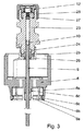
図3は、ネブライザ(1)の圧力発生器(5)を概略的に示しており、この圧力発生器は、図示の実施形態では、水性液調合薬を噴霧化すると共に特に蒸気圧の高い物質、又は特にアルコール化合物を溶剤として含む調合薬を噴霧化するのに適している。ピストンポンプシステムの一部である中空ピストン(9)は、圧力チャンバ(11)内に容器側で突き出ている。中空ピストン(9)は、圧力チャンバ(11)と容器(3)の内部との連結要素でもある。中空ピストン(9)又は類似の剛性管若しくは管状コンポーネント、例えば毛管又はカニューレは、容器3内に挿入されると、器具と容器(3)との間の流体結合部を作る。中空ピストン(9)が駆動ばね(7)の引張り操作プロセス中、圧力チャンバ(11)から部分的に引き出された場合、減圧状態が生じ、このような減圧状態により、液体(2)は、容器(3)から吸い出され、中空ピストン(9)内の逆止弁(10)を経て圧力チャンバ(11)内に吸い込まれ、この状況では、逆止弁(10)は開いている。中空ピストン(9)がネブライザ(1)を作動させているときに圧力チャンバ(11)内に入り込むと、逆止弁(10)は、中空ピストン内の受座へのその密封面の当接によって閉じられ、圧力チャンバ(11)内の液体は、フィルタシステム及びノズルを通って圧力下で放出される。中空ピストン(9)及び圧力チャンバ(11)は、エラストマーシール(24)によって外側に対して封止されており、エラストマーシール(24)は、特に、Oリングの形態をしていて、ネブライザ(1)の圧力チャンバ(11)又は計量チャンバ内へのその入口の近くでピストンの案内管内に配置されている。このシール(24)は、可動部品、即ち中空ピストン(9)からの空間を封止しているので、このようなシールは、動的シールと呼ばれることがある。高圧ポンプは、容器(3)への中空ピストン(9)の取付けとは別個のシール、特に動的シールによって中空ピストン(9)から封止される。図示の実施形態では、シール(24)は、止めナット(26)によって定位置に保持された支持リング(25)によって圧縮される。シール(24)の幾何学的取り付け位置は、例えば、国際公開第2007/051536(A1)号パンフレットに記載されている位置に一致している。
FIG. 3 schematically shows a pressure generator (5) of the nebulizer (1), which in the illustrated embodiment nebulizes an aqueous liquid preparation and has a particularly high vapor pressure. Or in particular suitable for nebulization of preparations containing alcohol compounds as solvents. A hollow piston (9), which is part of the piston pump system, projects into the pressure chamber (11) on the container side. The hollow piston (9) is also a connecting element between the pressure chamber (11) and the interior of the container (3). A hollow piston (9) or similar rigid tube or tubular component, such as a capillary or cannula, when inserted into the
圧力チャンバ(11)の液体出口領域には、フィルタシステム(27,28)が設けられ、このフィルタシステムは、流れ方向において好ましくは微細構造化ノズル(12)の前に配置され、そしてこのノズルを粒子の付着から保護している。高い付着率が種々のフィルタ(27,28)と濾過技術の組み合わせによって達成される。図示の実施形態の場合、ノズル(12)は、好ましくは、ガラス‐シリコン複合材から成る微細構造化コンポーネントによって形成され、この微細構造化コンポーネントは、それ自体、実際のノズルチャネルの前にフローフィルタとして設計された超微細フィルタを含む。これらノズルチャネルを通る液体の噴霧化は、好ましくは、直径数ミクロンに過ぎないノズルチャネルからの2つの顕微鏡的液体流相互間の高速衝突に依存している。 The liquid outlet region of the pressure chamber (11) is provided with a filter system (27, 28), which is preferably arranged in front of the microstructured nozzle (12) in the flow direction, and this nozzle is Protects against particle adhesion. High deposition rates are achieved by a combination of various filters (27, 28) and filtration techniques. In the case of the illustrated embodiment, the nozzle (12) is preferably formed by a microstructured component consisting of a glass-silicon composite, which itself is a flow filter before the actual nozzle channel. Including ultra-fine filters designed as: The atomization of liquid through these nozzle channels preferably relies on a high velocity impact between two microscopic liquid streams from the nozzle channel that are only a few microns in diameter.
中央部品(23)は、圧力チャンバ(11)の側方限度、液体運搬中空ピストン(9)のための通路の形態をした液体入口、中空ピストン(9)から見て封止を行うシール(24)のための設置空間及びノズル(12)及び種々の関連ホルダ又は封止コンポーネントを含むノズル組立体(29)への流体取付け部を形成している。円筒形圧力チャンバ(11)を含む図示の実施形態では、中央部品(23)は、中央ボア内に圧力チャンバ(11)に取り付けられた1つ又は2つ以上のフィルタコンポーネントを収容している。図示の実施例では、フィルタコンポーネントは、好ましくはプラスチック材料で作られた予備フィルタ(27)及び好ましくは金属で作られた微細フィルタ(28)である。さらに下流側には、上述の微細構造化コンポーネントが連結されており、この微細構造化コンポーネントは、超微細フィルタ及びノズルチャネルを含む。 The central part (23) has a lateral limit of the pressure chamber (11), a liquid inlet in the form of a passage for the liquid carrying hollow piston (9), a seal (24) sealing from the perspective of the hollow piston (9). ) And a fluid attachment to the nozzle assembly (29) including the nozzle (12) and various associated holders or sealing components. In the illustrated embodiment that includes a cylindrical pressure chamber (11), the central piece (23) houses one or more filter components attached to the pressure chamber (11) within the central bore. In the illustrated embodiment, the filter components are a pre-filter (27), preferably made of plastic material, and a fine filter (28), preferably made of metal. Further, on the downstream side, the above-mentioned microstructured component is connected, and this microstructured component includes an ultrafine filter and a nozzle channel.
図示の実施形態では、ネブライザ(1)又はその圧力発生器(5)は、容器(3)のためのホルダ(6)を有する。このホルダ(6)は、中空ピストン(9)にしっかりと連結され、好ましくは成形により取り付けられ、例えばこれ又接着され又はスナップ嵌めされる。駆動ばね(7)の軸方向引張り操作中、ホルダ(6)は、容器(3)及び中空ピストン(9)と一緒に、図中、下方に動かされる。容器(3)は、ホルダ(6)によって、特に、クランプ又はラッチ止め作用によってネブライザ(1)内に固定され、その結果、中空ピストン(9)は、容器(3)の流体チャンバ内に突き出ると共に/或いは容器(3)内の液体(2)に流体結合され、液体が中空ピストンを通って吸引されるようになっている。中空ピストン(9)と容器(3)は、容器(3)をホルダ(6)に連結した後、ネブライザ(1)の作動中、互いに対してもはや動かされず、即ち、容器(3)を器具にドッキングさせた後においては、器具と容器との間の接合部の封止に携わっているコンポーネントの相対運動が生じないようになっている。器具と容器(3)又は容器キャップ(31)との間のシールは、静的である。これは、液体それ自体の供給を漏れ及び拡散から保護する封止システムがどのような場合であっても摩擦応力を受けず、かくしてシールの摩耗が生じることがあり得ないという利点を有する。好ましくは、容器(3)及びホルダ(6)は、差込み形連結部を形成し、この差込み形連結部では、特に、ホルダ(6)の複数個のスナップインフック(6a)が容器(3)の上方部分内の包囲輪郭内に嵌まり込む。この輪郭は、例えば、包囲溝であっても良く或いは図示の実施形態の場合のように容器(3)を閉鎖する容器キャップ(31)の下方から縁部であっても良い。図示の実施形態では、ホルダは、4〜12個、好ましくは6又は12個のスナップインフック又はリブを有する。容器(3)がその容器キャップ(31)と一緒に中空ピストン(9)に沿ってホルダ(6)内に前方に押し込まれた場合、容器キャップ(31)は、先ず最初に、スナップインフック(6a)に設けられている挿入傾斜部又はスロープ(6b)に接触する。内方に傾斜した挿入傾斜部(6b)により、スナップインフック(6a)が容器キャップ(31)によって外方に広げられ、ついには、容器キャップ(31)は、スナップインフック(6a)の内方に向けられたビード(6c)を越えて摺動することができるようになる。容器キャップ(31)の下方外縁がビード(6c)を通過するやいなや、スナップインフック(6a)は、内方にスプリングバックし、その結果、ビード(6c)は、容器キャップ(31)の下縁部のところに容器(3)を固定するようになる。必要ならば、ホルダ(6)は、容器(3)が交換可能であるように構成されるのが良い。この交換性は、スナップインフック(6a)のばね特性によって達成される。ホルダ(6)の長さ、幅並びにとりわけ厚さ及び材料は、それに応じて選択される。ホルダ(6)は、好ましくは、熱可塑性樹脂、例えばPPO(ポリフェニレンオキシド)、PPE(ポリフェニレンエーテル)又はPBT(ポリブチレンテレフタレート)の中から選択されたプラスチックから成る。ホルダ(6a)の内周円上のビード(6c)の幾何学的形状及びビード(6c)の比率を互いに適合させる。ホルダ(6)中への容器(3)の挿入又はこれからの取出しに必要な力の微調整のため、スナップインフック(6a)を形成するためにホルダ上のリブのうちの幾つかにだけビード(6c)を設けることが有用である。かくして、例えば、図3に示されている実施形態におけるホルダ(6)は、ビード(6c)なしの全部で3つのリブを有する。ビード(6c)のないこれらリブは、ホルダ(6)中に挿入される容器(3)の半径方向案内に役に立つに過ぎない。 In the illustrated embodiment, the nebulizer (1) or its pressure generator (5) has a holder (6) for the container (3). This holder (6) is firmly connected to the hollow piston (9) and is preferably attached by molding, for example also glued or snapped on. During the axial pulling operation of the drive spring (7), the holder (6) is moved downward in the figure together with the container (3) and the hollow piston (9). The container (3) is fixed in the nebulizer (1) by means of a holder (6), in particular by clamping or latching action, so that the hollow piston (9) protrudes into the fluid chamber of the container (3) and Alternatively, it is fluidly coupled to the liquid (2) in the container (3) so that the liquid is sucked through the hollow piston. The hollow piston (9) and the container (3) are no longer moved relative to each other during operation of the nebulizer (1) after connecting the container (3) to the holder (6), i.e. the container (3) becomes an instrument. After docking, there is no relative movement of components involved in sealing the joint between the instrument and the container. The seal between the instrument and the container (3) or container cap (31) is static. This has the advantage that any sealing system that protects the supply of liquid itself from leakage and diffusion is not subject to frictional stress and thus seal wear cannot occur. Preferably, the container (3) and the holder (6) form a plug-in connection, in which, in particular, a plurality of snap-in hooks (6a) of the holder (6) are provided in the container (3). It fits within the encircling contour in the upper part. This contour may be, for example, an enclosed groove or an edge from below the container cap (31) that closes the container (3) as in the illustrated embodiment. In the illustrated embodiment, the holder has 4 to 12, preferably 6 or 12, snap-in hooks or ribs. When the container (3) is pushed forward together with its container cap (31) along the hollow piston (9) into the holder (6), the container cap (31) is first of all snap-in hook ( 6a) is brought into contact with the inclined slope or slope (6b). The snap-in hook (6a) is spread outward by the container cap (31) by the inwardly inclined insertion inclined portion (6b), and finally the container cap (31) is placed inside the snap-in hook (6a). It becomes possible to slide beyond the bead (6c) directed toward the direction. As soon as the lower outer edge of the container cap (31) passes through the bead (6c), the snap-in hook (6a) springs back inward so that the bead (6c) The container (3) is fixed at the part. If necessary, the holder (6) may be configured such that the container (3) is replaceable. This interchangeability is achieved by the spring characteristics of the snap-in hook (6a). The length, width and in particular thickness and material of the holder (6) are selected accordingly. The holder (6) is preferably made of a plastic selected from among thermoplastic resins such as PPO (polyphenylene oxide), PPE (polyphenylene ether) or PBT (polybutylene terephthalate). The geometry of the beads (6c) on the inner circumference of the holder (6a) and the ratio of the beads (6c) are adapted to each other. Beads only on some of the ribs on the holder to form a snap-in hook (6a) for fine adjustment of the force required to insert or remove the container (3) from the holder (6) It is useful to provide (6c). Thus, for example, the holder (6) in the embodiment shown in FIG. 3 has a total of three ribs without beads (6c). These ribs without the bead (6c) serve only for radial guidance of the container (3) inserted into the holder (6).
容器の交換性は、ホルダ(6)の特性だけでなくそのアクセス性によっても定められ、図1及び図2に示されている実施形態では、キャップ状下側ハウジング部品(18)がネブライザ内に挿入された容器(3)の自由端部領域を包囲したネブライザが示されている。下側ハウジング部品(18)は、保持要素又は安全クロージャ(19)によって解除可能に取り付けられ、特に、内側ハウジング部品(17)に装着される。特に、保持要素又は安全クロージャ(19)は、ネブライザ(1)の偶発的な開放又は下側ハウジング部品(18)の偶発的な取り外しを阻止するよう構成されている。下側ハウジング部品(18)を解除するためには、特に、安全クロージャ(19)をばね力に対抗して押し込む必要がある。安全クロージャ(19)は、好ましくは、内側ハウジング部品(17)の一部であり且つ/或いはこれに成形により取り付けられた型であり、例えばスプリングフックの形態に形作られている。 The exchangeability of the container is determined not only by the properties of the holder (6) but also by its accessibility, and in the embodiment shown in FIGS. 1 and 2, the cap-like lower housing part (18) is placed in the nebulizer. A nebulizer is shown surrounding the free end region of the inserted container (3). The lower housing part (18) is releasably attached by means of a holding element or a safety closure (19), in particular attached to the inner housing part (17). In particular, the holding element or safety closure (19) is configured to prevent accidental opening of the nebulizer (1) or accidental removal of the lower housing part (18). In order to release the lower housing part (18), it is necessary in particular to push the safety closure (19) against the spring force. The safety closure (19) is preferably a mold that is part of the inner housing part (17) and / or is molded attached thereto, for example in the form of a spring hook.
図示の実施形態の変形例として、ネブライザ(1)は又、容器(3)がネブライザ内にあらかじめ収納されるよう構成されていても良い。予備収納容器(3)(図面には示されていない)付きのこの変形例では、容器(3)は、工場でネブライザ(1)内に挿入され又は下側ハウジング部品(18)内の追加の保持又は固定要素内に挿入され、この下側ハウジング部品(18)は、供給時に内側ハウジング部品(17)上に部分的に押し嵌めされるに過ぎない。下側ハウジング部品(18)を更に内側ハウジング部品(17)上に押し嵌めすると、下側ハウジング部品(18)は、例えば一運動方向にのみ摺動するよう設計されたラチェット経路上を摺動し又は完全押し嵌め後、可変形態のラチェット機構体中に永続的に結合する。それと同時に、下側ハウジング部品を押し嵌めしている間、容器(3)をそのホルダ(6)内に押し込んで中空ピストン(9)に連結する。予備収納容器(3)を備えたこのようなシステムの構成のそれ以上の細部は、国際公開第2006/125577(A2)号パンフレットに見出される。 As a variation of the illustrated embodiment, the nebulizer (1) may also be configured so that the container (3) is pre-stored in the nebulizer. In this variant with a pre-container (3) (not shown in the drawing), the container (3) is inserted into the nebulizer (1) at the factory or additional in the lower housing part (18). Inserted into the holding or fixing element, this lower housing part (18) is only partially pressed onto the inner housing part (17) during delivery. When the lower housing part (18) is further pressed onto the inner housing part (17), the lower housing part (18) slides on a ratchet path designed to slide, for example, only in one movement direction. Alternatively, after a full press fit, it is permanently coupled into the deformable ratchet mechanism. At the same time, the container (3) is pushed into its holder (6) and connected to the hollow piston (9) while the lower housing part is being press fitted. Further details of the construction of such a system with a pre-container (3) can be found in WO 2006/1255577 (A2).
好ましくは、ここで検討中の医用器具は、液体調合薬の多数の投与ユニットを送り出すことができるよう設計されている。図1のネブライザ(1)は、カウンタ(41)、この特定の実施形態では、ハウジングの回転によって駆動されるスピンドル/カーソルカウンタを有し、このようなカウンタにより、ユーザ(図示せず)は、服用された投与ユニットの量又は器具内に残っている投与ユニットの量を読み取ることができる。器具内に挿入される容器は、多数の、例えば30〜180個の投与ユニットの取出しに十分な量の液体(2)を収容する。この多数回送り出しに鑑みて、ネブライザ(1)内に挿入される容器(3)は、内部圧力がたとえ液体を取り出しているときであっても実質的に不変のままであるようでなければならず、したがって、同一量の液体(2)が吸引時に常時取り出されるようになる。これは、基本的には、例えば国際公開第2006/136426(A1)号パンフレットに記載されているように内部圧力がベントによって一定に保たれる剛性容器壁を備えた容器(3)と液体を取り出しているときに容器の内部に少なくとも部分的に入り、内容積を減少させることによって内部圧力を液体の貯蔵場所のところで一定に保つ可撓性内壁を備えた容器(3)の両方を用いることによって達成できる。可撓性壁が実質的に変形可能であり、圧縮性であり且つ/或いは折り畳み可能である袋(32)、内袋又は箔袋によって形成された容器(3)が好ましい。この種の容器は、国際公開第00/49988(A2)号パンフレット、同第01/076849(A1)号パンフレット、同第99/435711(A1)号パンフレット、同第2009/11500(A1)号パンフレット及び同第2009/103510(A1)号パンフレットに種々の実施形態として記載されている。 Preferably, the medical device under consideration is designed to be able to deliver a number of liquid dispensing units. The nebulizer (1) of FIG. 1 has a counter (41), in this particular embodiment, a spindle / cursor counter that is driven by rotation of the housing, such that a user (not shown) can The amount of dose unit taken or the amount of dose unit remaining in the device can be read. The container inserted into the device contains a sufficient amount of liquid (2) for removal of a large number, for example 30 to 180 dosing units. In view of this multiple delivery, the container (3) inserted into the nebulizer (1) must remain substantially unchanged even when the internal pressure is being removed. Therefore, the same amount of liquid (2) is always taken out during suction. Basically, the container (3) having a rigid container wall whose internal pressure is kept constant by a vent as described in, for example, the pamphlet of International Publication No. 2006/136426 (A1) and a liquid. Use both a container (3) with a flexible inner wall that at least partially enters the interior of the container as it is being removed and keeps the internal pressure constant at the liquid storage location by reducing the internal volume Can be achieved. A container (3) formed by a bag (32), inner bag or foil bag, in which the flexible wall is substantially deformable, compressible and / or foldable, is preferred. This type of container is disclosed in International Publication No. 00/49988 (A2), No. 01/0776849 (A1), No. 99/435711 (A1), and No. 2009/11500 (A1). And the 2009/103510 (A1) pamphlet are described as various embodiments.
ここで選択した実施形態に関し、これら実施形態による容器の取付け部も又図4〜図9に詳細に示されており、液体(2)が柔軟性、変形可能且つ/或いは折り畳み可能な袋(32)又は管内に入れられた容器が好ましい。このように、液体の貯蔵場所のところの内部圧力を液体が取り出されているときに一定に保つことができ、この場合、気体又はガスの定期的な交換はネブライザ(1)の環境では行われない。ガスのこのような交換は、特に揮発性の高い溶剤、例えばエタノールを含む液体調合薬を用いる場合には、溶剤フラクションが各ガス抜きプロセスの際に気相を介して逃げ出るという欠点を有する。溶剤が気相を介して逃げ出る場合、容器(3)内の調合薬のために後に残る溶剤が少なくなり、活性物質が液体(2)中で濃縮される。この濃縮の結果として、計量された量の液体(2)を取り出したときに比較的増大した投与量の活性物質が抜き出される。かくして、気相を介するこの溶剤の損失は、制限されなければならず又は可能ならば阻止されなければならない。これは、容器(3)の構成、用いられる材料の選択及び容器(3)がそれぞれの器具又はネブライザ(1)内に挿入されるときのシールの構成に関する要件のうちの1つである。 For the embodiments selected here, the attachments of the containers according to these embodiments are also shown in detail in FIGS. 4 to 9, in which the liquid (2) is flexible, deformable and / or foldable. Or a container placed in a tube is preferred. In this way, the internal pressure at the liquid storage location can be kept constant when the liquid is being removed, in which case the periodic exchange of gas or gas takes place in the environment of the nebulizer (1). Absent. Such exchange of gases has the disadvantage that the solvent fraction escapes through the gas phase during each degassing process, especially when using liquid formulations containing highly volatile solvents such as ethanol. If the solvent escapes through the gas phase, less solvent remains behind for the drug in the container (3) and the active substance is concentrated in the liquid (2). As a result of this concentration, a relatively increased dose of active substance is withdrawn when a metered amount of liquid (2) is removed. Thus, this solvent loss through the gas phase must be limited or prevented if possible. This is one of the requirements regarding the configuration of the container (3), the choice of materials used and the configuration of the seal when the container (3) is inserted into the respective instrument or nebulizer (1).
好ましくは、液体(2)を収容する袋(32)のための可撓性壁部材として多層フィルム等が用いられる。このフィルムは、液体薬剤と適合性のあるプラスチック層及び金属層、例えばアルミニウム層等を含む。これにより、袋の壁を通るガスの拡散又は透過が最小限に抑えられる。 Preferably, a multilayer film or the like is used as a flexible wall member for the bag (32) that contains the liquid (2). The film includes a plastic layer and a metal layer compatible with the liquid drug, such as an aluminum layer. This minimizes gas diffusion or permeation through the bag wall.
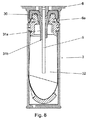
図示の実施形態のために選択された容器(3)は、内袋(32)、フランジ(32a)、容器キャップ(31)及び剛性スリーブ(34)を有する。底部が閉された柔軟性多層袋(32)は、その上方部分が好ましくはプラスチックで作られたフランジ(32a)に直接連結され、このフランジは、グリップとなっている。剛性スリーブ(34)は、袋(32)を包囲し、これを機械的損傷から外方に保護している。容器キャップ(31)は、好ましくは、プラスチック、最も好ましくはHD‐PE特にフランジ(32a)と同種又は類似の材料で作られる。袋(32)を液体(2)で充填した後、容器キャップ(31)を好ましくは熱成形プロセス又は溶接プロセス(例えば、超音波又はレーザ溶接)によりフランジ(32a)にしっかり連結する。容器キャップ(31)は、挿入箇所として、袋(32)の内部中に突き出た挿入漏斗状部(31a)を有し、この挿入漏斗状部は、容器をネブライザ(1)に取り付ける際に中空ピストン(9)のための心出し案内を形成し、かくして容器(3)が接合部に関して非制御状態で中空ピストン(9)により穴あけされるのを阻止する。ネブライザ(1)への取付け前に、容器(3)又は容器(3)の内部に向いた挿入漏斗状部(31a)の端部は、メンブレン(31b)で閉鎖され、このメンブレンは、中空ピストン(9)を挿入したときに穴あけされ又はめくって開かれる。このように、メンブレン(31b)は、非穴あけ容器を液体が逃げ出さないよう保護する。更に、貯蔵器中、容器にトップシールを提供する手段(図面には示されていない)が存在し、このトップシールは、例えば金属箔、好ましくはアルミニウムから成るのが良く、このようなトップシールは、挿入漏斗状部(31a)の上方開口端を閉鎖する。この種のシールは、出所保証として役立つと共に個々のカートリッジの輸送中、挿入漏斗状部(31a)を汚染から保護することができる。場合によってはメンブレン(31b)を通過する場合のあるガスは、金属製トップシールによって止められる。容器(3)を器具内に収納する前に、例えば突出タブを用いてトップシールを引き剥がすことによってトップシールを取り外すのが良い。 The container (3) selected for the illustrated embodiment has an inner bag (32), a flange (32a), a container cap (31) and a rigid sleeve (34). The flexible multi-layer bag (32) closed at the bottom is directly connected at its upper part to a flange (32a), preferably made of plastic, which is the grip. A rigid sleeve (34) surrounds the bag (32) and protects it outward from mechanical damage. The container cap (31) is preferably made of plastic, most preferably HD-PE, especially the same or similar material as the flange (32a). After filling the bag (32) with the liquid (2), the container cap (31) is securely connected to the flange (32a), preferably by a thermoforming process or a welding process (eg ultrasonic or laser welding). The container cap (31) has an insertion funnel-shaped part (31a) protruding into the bag (32) as an insertion point, and this insertion funnel-shaped part is hollow when the container is attached to the nebulizer (1). A centering guide for the piston (9) is formed, thus preventing the container (3) from being drilled by the hollow piston (9) in an uncontrolled manner with respect to the joint. Prior to attachment to the nebulizer (1), the end of the insertion funnel (31a) facing the container (3) or the interior of the container (3) is closed with a membrane (31b), which is a hollow piston When (9) is inserted, it is drilled or flipped open. Thus, the membrane (31b) protects the non-drilled container from liquid escape. In addition, there is a means (not shown in the drawings) for providing a top seal to the container in the reservoir, which top seal may consist of, for example, a metal foil, preferably aluminum, such a top seal. Closes the upper open end of the insertion funnel (31a). This type of seal can serve as a source guarantee and protect the insertion funnel (31a) from contamination during transport of individual cartridges. In some cases, gas that may pass through the membrane (31b) is stopped by a metal top seal. Prior to storing the container (3) in the instrument, the top seal may be removed, for example by peeling off the top seal using a protruding tab.
容器(3)をネブライザ(1)のホルダ(6)内に完全に挿入した後、挿入状態の管又は中空ピストン(9)と挿入漏斗状部(31a)の壁との間には圧力嵌め関係が生じる。挿入漏斗状部(31a)の一方の部分のこの圧力嵌め状態は、容器キャップ(31)の一部であり、第1のシールとも呼ぶシールを形成する。半径方向に作用する圧力嵌めは、1〜10ミリメートル、好ましくは2〜7ミリメートル、最も好ましくは5mmの長さにわたって液体が中空ピストン(9)の外側を通って抜け出ないよう中空ピストン(9)と容器(3)の内部との間の接触箇所を封止する。図示の実施形態では、中空ピストン(9)は、金属、好ましくはステンレス鋼で作られる。容器キャップ(31)は、中空ピストン(9)よりも軟質のプラスチック材料、好ましくはPE又はHD‐PEから成る。しかしながら、容器キャップ(31)の材料は、固有の安定性がシステムの動作信頼性にとって重要なので、無制限に軟質のものであってはならない。この理由で、中空ピストン(9)と挿入漏斗状部(31a)との間の圧力嵌め部は、液体の通過を止めるが、必ずしもガスの透過を止めることがないよう止めるよう設計されるのが良い。中空ピストン(9)の製造方法に応じて、例えば、その表面上に数ミクロン深さまでのしわ又は不均一な領域が存在する場合があり、これらは、圧力嵌め部を通るガスの透過に好都合である。この理由で、圧力嵌め部とは異なる封止特性を備えた第2のシール(30)が圧力嵌め部を通って逃げ出たガスを捕捉するためにこの箇所に取り付けられるか或いは空気が中空ピストン(9)を越えて外側からシステムに入るのを阻止するために接近領域に設けられるかのいずれかを行う。図4〜図9は、第2のシール(30)の種々の実施形態を示している。ホルダ(6)及び中空ピストン(9)は、図面を簡単にするために(これらコンポーネントの完全な記載は図1〜図3に見える)これらの下方部分だけが示されている。図4は、管、例えば中空ピストン(9)の外側に又は容器のための入れ物を形成し、器具に設けられるホルダ(6)上に追加の封止コンポーネントとして取り付けられた第2のシール(30)の実施例を示している。この場合、容器キャップ(31)及び中空ピストン(9)を挿入漏斗状部(31a)の上方部分において、即ち、中空ピストン(9)との圧力嵌め部の上方のその広幅部分において互いに封止する半径方向に対称のシール(30)が示されている。第1のシールと比較して器具側に設けられたこの第2のシール(30)は、中空ピストン(9)をホルダ(6)の付近で半径方向に、即ち、直接的に又は内側案内(6d)により生じる間隔を置いたところで包囲している。シール(30)は、この場合、その上方側部が、中空ピストン(9)に沿って容器(3)に向かって下方に僅かなところまで引かれたホルダ(6)、特に内側案内(6d)に当接する。コンポーネントとして具体化されたシール(30)は、内側が中空ピストン(9)を案内する円筒形凹部を有し、上方部分がこの実施形態では漏斗の形をしていて、ホルダ(6)の内側案内(6d)の形状に適合した形態を有し、外側が容器(3)に向かってテーパした円錐形の形態を有する。この円錐形の形態は、容器キャップ(31)の挿入漏斗状部(31a)の内側輪郭に対応した輪郭を形成している。ホルダ(6)により中空ピストン(9)と共に案内されるシール(30)は、中空ピストン(9)の挿入のために容器(3)又は容器キャップ(31)に設けられた円錐形開口部内に突き出る。収納位置では、第2のシール(30)は、容器キャップ(31)の挿入漏斗状部(31a)の円錐形壁部分内に設けられたシールとなる。 After completely inserting the container (3) into the holder (6) of the nebulizer (1), there is a press-fitting relationship between the inserted tube or hollow piston (9) and the wall of the insertion funnel (31a). Occurs. This press-fit state of one part of the insertion funnel-shaped part (31a) is a part of the container cap (31) and forms a seal also called a first seal. The radially acting pressure fit is with the hollow piston (9) so that liquid does not escape through the outside of the hollow piston (9) over a length of 1-10 millimeters, preferably 2-7 millimeters, most preferably 5 mm. A contact point between the inside of the container (3) is sealed. In the illustrated embodiment, the hollow piston (9) is made of metal, preferably stainless steel. The container cap (31) is made of a softer plastic material than the hollow piston (9), preferably PE or HD-PE. However, the material of the container cap (31) must not be unlimitedly soft, as inherent stability is important to the operational reliability of the system. For this reason, the pressure fit between the hollow piston (9) and the insertion funnel (31a) is designed to stop the passage of liquid but not necessarily stop the permeation of gas. good. Depending on the method of manufacturing the hollow piston (9), for example, there may be wrinkles or non-uniform areas up to a few microns deep on its surface, which favor gas permeation through the pressure fit. is there. For this reason, a second seal (30) with a sealing characteristic different from that of the press-fitting part is attached to this point in order to capture the gas escaping through the press-fitting part or the air is a hollow piston. (9) Do one of those provided in the access area to prevent entry from outside into the system. 4-9 illustrate various embodiments of the second seal (30). The holder (6) and the hollow piston (9) are shown only in their lower part for the sake of simplicity of the drawing (a complete description of these components can be seen in FIGS. 1-3). FIG. 4 shows a second seal (30) formed as an additional sealing component on the outside of a tube, for example a hollow piston (9) or on a holder (6) provided on the instrument. ). In this case, the container cap (31) and the hollow piston (9) are sealed together in the upper part of the insertion funnel (31a), that is, in the wide part above the pressure fitting with the hollow piston (9). A radially symmetrical seal (30) is shown. This second seal (30) provided on the instrument side compared to the first seal allows the hollow piston (9) to be guided radially in the vicinity of the holder (6), ie directly or inwardly ( Surrounding at the interval generated by 6d). The seal (30) is in this case a holder (6) whose upper side is pulled down slightly towards the container (3) along the hollow piston (9), in particular the inner guide (6d). Abut. The seal (30) embodied as a component has a cylindrical recess on the inside which guides the hollow piston (9) and the upper part in this embodiment is in the form of a funnel, and the inside of the holder (6) It has a form adapted to the shape of the guide (6d) and has a conical form with the outside tapering towards the container (3). This conical form forms a contour corresponding to the inner contour of the insertion funnel portion (31a) of the container cap (31). The seal (30) guided with the hollow piston (9) by the holder (6) protrudes into a conical opening provided in the container (3) or container cap (31) for insertion of the hollow piston (9). . In the stowed position, the second seal (30) is a seal provided in the conical wall portion of the insertion funnel (31a) of the container cap (31).
好ましくは、シール(30)は、中空ピストン(9)を包囲すると共に内側案内(6d)によって支持された状態でホルダ(6)にあらかじめ組み付けられる。次に、容器(3)をネブライザ(1)内に挿入して中空ピストン(9)上に軸方向に押し嵌めした場合、シール(30)は、内側案内(6d)と容器キャップ(31)上の挿入漏斗状部(31a)の内壁との間で軸方向に圧縮される。器具への容器(3)の取付け部を全体として見ると、封止作用が特に管状コンポーネント又は中空ピストン(9)に平行に軸方向圧縮によって且つ特に中空ピストン(9)に垂直に半径方向圧縮によって得られる。中空ピストン(9)と容器キャップ(31)との間の圧力嵌め部の形態をした半径方向に作用するシールと容器キャップ(31)と容器入れ物との間の本質的に軸方向に作用する追加のシール(30)の組み合わせによって、システムは、二重作用シールを備える。シール(30)は、好ましくは、エラストマー、例えばシリコン及び/又は炭素を主成分とするエラストマーポリマーから成る。適当な材料としては、天然及び合成エラストマー、例えばニトリルゴム、ブタジエンゴム、スチレン‐ブタジエンゴム、イソプレンゴム、スチレン‐イソプレンコポリマー、ブチルゴム、例えばイソブテン‐イソプレンゴム、ポリウレタン、弗素ゴム、シロキサン、例えば特にシリコーン及びジエン、例えば特にEPDM(エチレン‐プロピレン‐ジエンゴム)又は医療分野で用いられるのに適した他のエラストマーが挙げられる。要件、例えば組み立てプロセスと関連した特定の材料抵抗又は摩擦特性の必要性に応じて、シールを更に被覆するのが良い。かくして、例えば、弗素ゴムから成るPTFE(ポリテトラフルオロエチレン)で被覆された封止コンポーネントが大量生産のための組み立て機械に関する選択性の向上という技術背景に対して有利である。 Preferably, the seal (30) is pre-assembled to the holder (6) in a state of surrounding the hollow piston (9) and supported by the inner guide (6d). Next, when the container (3) is inserted into the nebulizer (1) and axially pushed onto the hollow piston (9), the seal (30) is placed on the inner guide (6d) and the container cap (31). It is compressed in the axial direction between the inner wall of the insertion funnel-shaped part (31a). Looking at the attachment of the container (3) to the device as a whole, the sealing action is in particular by axial compression parallel to the tubular component or hollow piston (9) and in particular by radial compression perpendicular to the hollow piston (9). can get. A radially acting seal in the form of a pressure fit between the hollow piston (9) and the container cap (31) and an essentially axially acting addition between the container cap (31) and the container container. With the combination of the seals (30), the system comprises a dual action seal. The seal (30) preferably consists of an elastomer, for example an elastomer polymer based on silicon and / or carbon. Suitable materials include natural and synthetic elastomers such as nitrile rubber, butadiene rubber, styrene-butadiene rubber, isoprene rubber, styrene-isoprene copolymer, butyl rubber such as isobutene-isoprene rubber, polyurethane, fluorine rubber, siloxane such as especially silicone and Mention may be made of dienes such as in particular EPDM (ethylene-propylene-diene rubber) or other elastomers suitable for use in the medical field. Depending on the requirements, such as the need for specific material resistance or friction properties associated with the assembly process, the seal may be further coated. Thus, for example, a sealing component coated with PTFE (polytetrafluoroethylene) made of fluorine rubber is advantageous against the technical background of improved selectivity for assembly machines for mass production.
シール(30)について軟質エラストマー、特に40〜70ショア硬さのショア硬さを有するエラストマーの使用は、挿入漏斗状部(31a)と中空ピストン(9)の両方に関して硬質/軟質シールが形成されるという利点を有する。かくして、挿入漏斗状部(31a)及び中空ピストン(9)の比較的硬質の表面の不均一又はでこぼこをシール(30)によって平らにすることができ、その結果、コンポーネント相互間の移行領域も又、揮発性物質の面で漏れ止め状態になる。かくして、シール(30)を気相シールと呼ぶことができる。と言うのは、中空ピストン(9)に沿うガスの透過がこの場合阻止されるからである。図4の特定の実施形態に示されているシール(30)は、これが挿入漏斗状部(31a)中に突き出て、かくして、第2のシール(30)と中空ピストン(9)と第1のシール(中空ピストン(9)と容器キャップ(31)との間の圧力嵌め部)との間の死空間、即ち未使用自由空間が比較的小さく保たれるという追加の利点を有する。死空間は、容器(3)が器具内に収納される限り一定である。シールに関与するコンポーネントは、器具又はネブライザ(1)の作動中、互いに向かって動くことはない。死空間を最小限に抑えた結果として、圧力嵌め部を通る袋(32)からのガスの透過中、平衡状態が迅速に生じ、その結果、ガスの逃げ出しによって失われる物質の全ての量を極めて僅かに保つことができる。図示の実施形態では、蒸気圧の最も高い露出は、通常、袋(32)内の調合薬の溶剤である。溶剤の損失分を結果的に最小限に抑えることは、溶液中の活性物質の濃縮を阻止する。試験結果の示すところによれば、第2のシール(30)の作用効果の長期間にわたる良好な安定性が得られた。シール(30)を用いた器具内に収納されている容器(3)の重量法により求められた蒸発値は、これらの材料に応じて、無傷のメンブレン(31b)を備えた非穴あき容器(3)と同じほど低かった。袋(32)の全容量が約4ミリリットルである場合、試験対象の封止材料の全て及び個々のサンプルの全てにおけるエタノールに関する蒸発値は、この実験について設定されたしきい値を著しく下回っており、容器キャップと器具との間の2つのシールにより形成される封止システムは、1日当たり0.3ミリグラム未満のエタノール透過性を示した。達成された結果は、平均で、1日当たり0.005〜0.04ミリグラムであった。それ自体エタノールについてその部分透過性があるものとして知られているエラストマー、例えばシリコーンを用いた場合であっても、測定した最も高い個々の値は、一日当たり0.15ミリグラム未満であった。 The use of a soft elastomer for the seal (30), in particular an elastomer having a shore hardness of 40-70 shore hardness, forms a hard / soft seal for both the insertion funnel (31a) and the hollow piston (9). Has the advantage. Thus, the non-uniformity or unevenness of the relatively hard surface of the insertion funnel (31a) and the hollow piston (9) can be flattened by the seal (30), so that the transition area between components is also , Leak-proof in terms of volatile substances. Thus, the seal (30) can be referred to as a gas phase seal. This is because gas permeation along the hollow piston (9) is prevented in this case. The seal (30) shown in the particular embodiment of FIG. 4 protrudes into the insertion funnel (31a), thus the second seal (30), the hollow piston (9) and the first It has the additional advantage that the dead space between the seals (pressure fitting between the hollow piston (9) and the container cap (31)), ie the unused free space, is kept relatively small. The dead space is constant as long as the container (3) is stored in the instrument. The components involved in the seal do not move towards each other during operation of the instrument or nebulizer (1). As a result of minimizing the dead space, equilibrium occurs quickly during the permeation of gas from the bag (32) through the press fit, so that all the amount of material lost by gas escape is greatly reduced. It can be kept slightly. In the illustrated embodiment, the highest vapor pressure exposure is usually the solvent of the pharmaceutical agent in the bag (32). As a result, minimizing the loss of solvent prevents concentration of the active substance in the solution. According to the test results, good stability over a long period of the effect of the second seal (30) was obtained. The evaporation value determined by the gravimetric method of the container (3) housed in the instrument using the seal (30) depends on these materials, and is a non-perforated container with an intact membrane (31b) ( It was as low as 3). If the total volume of the bag (32) is about 4 milliliters, the evaporation values for ethanol in all of the sealing materials tested and all of the individual samples are significantly below the threshold set for this experiment. The sealing system formed by two seals between the container cap and the instrument showed an ethanol permeability of less than 0.3 milligrams per day. The achieved results averaged 0.005 to 0.04 milligrams per day. The highest individual values measured were less than 0.15 milligrams per day, even when using elastomers, such as silicones, which are known to be partially permeable to ethanol per se.
図5は、コンポーネントとして具体化された収納状態にある第2のシール(30)の別の実施形態を示している。シール(30)の材料は、図4の実施形態で用いられた材料と一致している。この実施形態の場合と同様、特定の用途について、特に調合薬中に含まれている物質に対して拡散防止性を示し、即ち、例えば溶剤のガス透過を許容しない材料が用いられるべきである。 FIG. 5 shows another embodiment of the second seal (30) in the stowed state embodied as a component. The material of the seal (30) is consistent with the material used in the embodiment of FIG. As with this embodiment, for a particular application, a material should be used that exhibits anti-diffusion properties, especially for substances contained in the drug product, i.e. does not allow, for example, solvent gas permeation.
シール(30)を形成している図5に示されたコンポーネントも又、半径方向対称であり、底部のところが開かれたカップ又はキャップの形状をしている。カップの開口部は、中空ピストン(9)の通路である。封止コンポーネントの内側形状又はカップの内側輪郭は、中空ピストン(9)の付近におけるホルダ(6)の内側案内(6d)の形状に対応している。特定の実施形態では、封止コンポーネントは、下方に円錐状にテーパした領域中に合体する上側円筒形領域を有する。カップの底部は、漏斗の形をしている。封止は、ホルダ(6)の内側案内(6d)と容器キャップ(31)の円筒形開放領域(31c)との間におけるシール(30)の純粋に半径方向に作用する圧縮によって行われる。この円筒形開放領域(31c)は、容器キャップ(31)の上方に挿入漏斗状部(31a)に隣接して位置している。かくして、この実施形態では、2つのシールは、容器(3)又は容器キャップ(31)と中空ピストン(9)又はホルダ(6)との間の半径方向圧縮によって形成される。シール(30)の半径方向作用は、容器(3)を器具中に挿入したときに追加の軸方向力を加える必要がないという利点を有する。 The component shown in FIG. 5 forming the seal (30) is also radially symmetric and takes the form of a cup or cap that is open at the bottom. The opening of the cup is a passage for the hollow piston (9). The inner shape of the sealing component or the inner contour of the cup corresponds to the shape of the inner guide (6d) of the holder (6) in the vicinity of the hollow piston (9). In certain embodiments, the sealing component has an upper cylindrical region that merges into a downwardly conically tapered region. The bottom of the cup has a funnel shape. The sealing is effected by a purely radially acting compression of the seal (30) between the inner guide (6d) of the holder (6) and the cylindrical open area (31c) of the container cap (31). This cylindrical open region (31c) is located above the container cap (31) and adjacent to the insertion funnel (31a). Thus, in this embodiment, the two seals are formed by radial compression between the container (3) or container cap (31) and the hollow piston (9) or holder (6). The radial action of the seal (30) has the advantage that no additional axial force needs to be applied when the container (3) is inserted into the instrument.
第2のシール(30)を形成しているコンポーネントは、この場合、軸方向において器具の別のコンポーネント、特にホルダ(6)に当接する支持領域を有するよう形作られている。封止コンポーネントのキャップ形状又はカップ形状構成は、ホルダ(6)の内側案内(6d)の下縁に適合しており、封止要素のための支持領域を形成するカップの内側ベースは、底部が内側案内(6d)に当接している。かくして、シール(30)を形成するコンポーネントの支持領域は、容器(3)中に突き出たホルダ(6)の領域に当接する。極めて軟質の封止材料が用いられた場合であっても、封止コンポーネントは、この支持体によって定位置に保持され、ドッキング中、即ち、容器(3)をホルダ(6)中に挿入しているとき、容器は、容器キャップ(31)とホルダ(6)との間の上方軸方向空間中において軸方向に作用する力によっては動かされない。第2のシール(30)と容器キャップ(31)と中空ピストン(9)と圧力嵌め部(第1のシール)との間の死空間を減少させるため、封止コンポーネントの非封止支持下方領域を拡張させるのが良い。好ましくは、シール(30)を形成するコンポーネントのこの下方領域は、容器キャップ(31)の挿入漏斗状部(31a)との直接的な壁接触関係をなしておらず、したがって、容器(3)のドッキング中、追加の軸方向力が働くことはない。 The component forming the second seal (30) is in this case shaped to have a support area that abuts against another component of the instrument, in particular the holder (6), in the axial direction. The cap-shaped or cup-shaped configuration of the sealing component is adapted to the lower edge of the inner guide (6d) of the holder (6), the inner base of the cup forming the support area for the sealing element is It is in contact with the inner guide (6d). Thus, the support area of the component forming the seal (30) abuts the area of the holder (6) protruding into the container (3). Even when a very soft sealing material is used, the sealing component is held in place by this support and during docking, i.e. the container (3) is inserted into the holder (6). The container is not moved by axially acting forces in the upper axial space between the container cap (31) and the holder (6). Non-sealing support lower region of the sealing component to reduce the dead space between the second seal (30), the container cap (31), the hollow piston (9) and the pressure fitting (first seal) It is good to extend. Preferably, this lower region of the component forming the seal (30) is not in direct wall contact with the insertion funnel (31a) of the container cap (31) and thus the container (3) No additional axial force is applied during docking.
図6及び図7は、収納状態にあるシール(30)の別の2つの実施形態を示している。図5の実施形態と同様、シールは、ホルダ(6)の内側案内(6d)と容器キャップ(31)の内壁との間で半径方向に又は具体的言えば挿入漏斗状部(31a)の上方で円筒形開放領域(31c)内で作用する。シール(30)の半径方向作用の結果として、容器(3)を器具中に挿入しているときに追加の軸方向力をそれほど加える必要がない。シールは、両方の側が硬質‐軟質シールであり、この場合、シール(30)の見かけ上軟質材料は、容器キャップ又は封止領域におけるホルダ(6)の内側案内(6d)の表面不均一さ又はでこぼこを平らにする。シール(30)は、ホルダ(6)(図6)の内側案内(6d)に装着されるフラットリングシールの形をしていても良く、或いは、内側案内(6d)を半径方向に押し下げることによって定位置に保持される内側案内(6d)(図7)内に配置されたフラット又はOリング形シール(30)の形状をしていても良い。さらに、内側案内それ自体は、下方に円錐状に広がっていても良く、内側案内の形状に適合したシール(30)は、下方且つ内方に拡張するリングであっても良く、このリングは、内側案内(6d)上に内方に支持される(図面に示されていない変形例)。 6 and 7 show two other embodiments of the seal (30) in the stowed state. Similar to the embodiment of FIG. 5, the seal is radially between the inner guide (6d) of the holder (6) and the inner wall of the container cap (31), or more specifically above the insertion funnel (31a). In the cylindrical open area (31c). As a result of the radial action of the seal (30), little additional axial force needs to be applied when the container (3) is inserted into the instrument. The seal is a hard-soft seal on both sides, in which case the apparently soft material of the seal (30) is not surface unevenness of the inner guide (6d) of the holder (6) in the container cap or sealing area or Flatten bumps. The seal (30) may be in the form of a flat ring seal attached to the inner guide (6d) of the holder (6) (FIG. 6) or by pushing the inner guide (6d) down in the radial direction. The inner guide (6d) held in place (6d) (FIG. 7) may be in the form of a flat or O-ring seal (30). Furthermore, the inner guide itself may extend conically downwards, and the seal (30) adapted to the shape of the inner guide may be a ring that expands downward and inward, which ring is It is supported inward on the inner guide (6d) (variation not shown in the drawing).
図4〜図7の実施形態としてのシール(30)の好ましい組み立て方法は、次のとおりである。 A preferred method of assembling the seal (30) as the embodiment of FIGS. 4 to 7 is as follows.
先ず最初に、ホルダ(6)のプラスチック材料を任意の射出成形法により中空ピストン(9)に直接成形して取り付けることにより中空ピストン(9)をホルダ(6)にしっかりと固定する。次に、中空ピストン(9)を備えたホルダ(6)を容器側が(即ち、この場合底部のところが)開放しているが、もしそうでなければ完全に組み立てられたネブライザ(1)内に納める。ネブライザ(1)内におけるホルダ(6)の組み立て前又は好ましくは組み立て後、シール(30)を形成している半径方向対称のコンポーネントを中空ピストン(9)に沿って心出し状態で下からホルダ(6)又は内側案内(6d)上のその定位置に押す。このプロセスは、好ましくは、中空ピストンへの損傷、例えば第1のシール、この実施形態では、中空ピストン(9)と容器キャップ(31)との間の圧力嵌め部により作られるシールの有効性を弱める場合のある縦じわ又は他の不均一さを生じさせないよう何ら接触しないで実施される。 First, the hollow piston (9) is firmly fixed to the holder (6) by directly molding and attaching the plastic material of the holder (6) to the hollow piston (9) by any injection molding method. The holder (6) with the hollow piston (9) is then opened in the container side (ie at the bottom in this case), but if not, it is placed in a fully assembled nebulizer (1). . Before or preferably after assembling the holder (6) in the nebulizer (1), the radially symmetrical components forming the seal (30) are centered along the hollow piston (9) from below in the holder ( 6) or push to its home position on the inner guide (6d). This process preferably increases the effectiveness of the damage made to the hollow piston, for example the first seal, in this embodiment the seal created by the pressure fit between the hollow piston (9) and the container cap (31). It is performed without any contact so as not to cause vertical lines or other non-uniformities that may weaken.
接触なしの組み立てを行うため、破断時伸び率が少なくとも200%、好ましくは破断時伸び率が300%〜500%の材料をシール(30)について用いる。この関係で、これは、半径方向対称のコンポーネントをコンポーネントの直径を亀裂が生じることなくそのサイズの少なくとも2倍、好ましくは3〜4倍まで拡張させることができるということを意味している。この材料は又、コンポーネントがこの負荷中、純粋に弾性変形を生じ、次にその元の形状に戻るよう選択されなければならない。シール(30)を形成するコンポーネントの組み立ては、好ましくは、少なくとも3本のグリッパアームがコンポーネントに設けられた円形ツール内に突き出てこれを内側から外方に広げる器具を用いることによって行われる。広がりコンポーネントを中空ピストン(9)上でこれに沿ってホルダ(6)上のその定位置に押す。グリッパ相互間で内側に設けられたプラスチックスリーブは、更に、中空ピストンを保護するのに役立ち得る。シール(30)を形成しているコンポーネントが中空ピストン(9)又はホルダ(6)上のその軸方向定位置に達するやいなや、外側スリーブを前進させ、グリッパアームを引っ込めているときにそのコンポーネントをグリッパアームから下方に押す。封止コンポーネントの形状又は支持領域の存在に応じて、シール(30)を形成しているコンポーネントの位置の別途微調整は又、容器キャップ(31)、シール(30)及びホルダ(6)がオプションとして軸方向に更に一緒に押される場合、容器(3)がネブライザ(1)にドッキングされている間に行える。送り出し前における予備組み立てネブライザ(1)内におけるシール(30)を形成しているコンポーネントの組み立て後、予備組み立てネブライザを望ましい場合、容器なしで下側ハウジング部品(18)で閉鎖するのが良く又は好ましくは、予備組み立てシステムを形成するよう部分ドッキング容器(3)及び下側ハウジング部品(18)を備えた状態で完成させる。 For assembly without contact, a material with an elongation at break of at least 200%, preferably an elongation at break of 300% to 500% is used for the seal (30). In this context, this means that a radially symmetric component can be expanded to at least twice, preferably 3-4 times its size, without cracking the component diameter. This material must also be selected so that the component undergoes pure elastic deformation during this loading and then returns to its original shape. The assembly of the component forming the seal (30) is preferably done by using an instrument in which at least three gripper arms protrude into a circular tool provided on the component and spread it from the inside to the outside. The spreading component is pushed onto the hollow piston (9) along its position on the holder (6). A plastic sleeve provided on the inside between the grippers can further help protect the hollow piston. As soon as the component forming the seal (30) reaches its axial home position on the hollow piston (9) or holder (6), the outer sleeve is advanced and the gripper arm is retracted when the gripper arm is retracted. Push down from the arm. Depending on the shape of the sealing component or the presence of the support area, the container cap (31), seal (30) and holder (6) are also optional for further fine adjustment of the position of the component forming the seal (30). As well as being pushed together in the axial direction while the container (3) is docked to the nebulizer (1). After assembly of the components forming the seal (30) in the pre-assembled nebulizer (1) prior to delivery, if desired, the pre-assembled nebulizer may be closed with the lower housing part (18) without a container. Is completed with a partial docking container (3) and a lower housing part (18) to form a pre-assembly system.
図8は、封止作用がホルダ(6)と容器キャップ(31)との嵌合によって達成される第2のシール(30)の別の実施形態を示している。ホルダ(6)又はその内側案内(6d)は、これが容器キャップ(31)に直接当接することによってシール(30)それ自体を形成するよう形作られている。これは、製造費及び組み立て方法の面で特に有利である。というのは、追加のコンポーネントを取り付けることなくシール(30)を形成することができるからである。ホルダ(6)は、中空ピストン(9)を中央部分に沿って包囲し、そしてホルダ(6)は、特に成形によってこれに永続的に取り付けられる。中空ピストンに当接している内側案内(6d)は、全ての実施形態においてホルダ(6)の全直径と比較して著しく細く、ホルダ(6)への容器(3)の取付け後、ホルダ(6)は、この容器中に突き出る。次に、内側案内(6d)の下縁を容器(3)の上縁よりも下に配置する。内側案内は、多少なりとも容器キャップ(31)の挿入漏斗状部(31a)中に突き出る。 FIG. 8 shows another embodiment of the second seal (30) in which the sealing action is achieved by fitting the holder (6) and the container cap (31). The holder (6) or its inner guide (6d) is shaped so that it forms the seal (30) itself by directly abutting the container cap (31). This is particularly advantageous in terms of manufacturing costs and assembly methods. This is because the seal (30) can be formed without attaching additional components. The holder (6) surrounds the hollow piston (9) along the central part, and the holder (6) is permanently attached to it, in particular by molding. The inner guide (6d) in contact with the hollow piston is significantly thinner than the entire diameter of the holder (6) in all embodiments, and after mounting the container (3) to the holder (6), the holder (6 ) Protrudes into this container. Next, the lower edge of the inner guide (6d) is placed below the upper edge of the container (3). The inner guide protrudes more or less into the insertion funnel (31a) of the container cap (31).
図8に示されている変形例の材料の選択に応じて、この第2のシール(30)は、硬質‐硬質シールである。と言うのは、ホルダ(6)及び容器キャップ(31)の保持特性に関する要件により、特に、両方のコンポーネントは、或る程度の剛性を有することが必要だからである。 Depending on the alternative material selection shown in FIG. 8, this second seal (30) is a hard-hard seal. This is because, due to the requirements regarding the holding properties of the holder (6) and the container cap (31), in particular, both components need to have a certain degree of rigidity.
容器キャップ(31)の場合、確かに、この関係においてホルダ(6)について用いられる材料よりも見かけ上、軟質の材料が用いられるのが良いが、容器キャップ(31)は、或る程度の剛性を備えなければならない。図示の実施形態では、内側案内(6d)は、上側開放領域において容器キャップ(31)に当接するよう形作られている。図6及び図7の実施例と同様、内側案内は、円筒形開放領域(31c)内にシールを形成することができ、或いは図8に示されているように、内側案内は、円筒形開放領域(31c)の入口領域内に、即ち、製造中丸くされる表面領域内にシールを形成しても良く、製造時、容器キャップ(31)の頂端部は、円筒形開放領域(31c)に合体する。図面に示されていない別の実施形態では、内側案内(6d)も又、挿入漏斗状部(31a)の上方領域内で直接当接することができる。この場合、内側案内は、良好なシールを形成するよう挿入漏斗状部(31a)の表面中に、即ち、内方に収斂する傾斜部又はスロープ中に押し入る包囲状態の尖った縁を形成する。この縁は、好ましくは半径方向だけでなく軸方向にも一点になり、即ち、内側案内(6d)の外側下縁は、容器(3)の方向に、次に材料の成形によって形成された内側案内(6d)と中空ピストン(9)との間の材料接触部の方向に突き出る。かくして、中空ピストン(9)の付近において、内側案内(6d)は、図示されていないこの実施形態ではアンダーカットを有している。内側案内(6d)により形成されるこれらシール(30)は、軸方向に作用し、その結果、図4に示された実施形態の場合と同様、これらシールは、中空ピストン(9)と容器キャップ(31)との間の半径方向に作用する封止圧力嵌め部のための適当な組み合わせを形成する。 In the case of the container cap (31), it is true that a softer material is apparently used than the material used for the holder (6) in this connection, but the container cap (31) has a certain degree of rigidity. Must be provided. In the illustrated embodiment, the inner guide (6d) is shaped to abut the container cap (31) in the upper open area. Similar to the embodiment of FIGS. 6 and 7, the inner guide can form a seal in the cylindrical open area (31c), or, as shown in FIG. A seal may be formed in the inlet region of the region (31c), ie in the surface region that is rounded during manufacture, and during manufacture, the top end of the container cap (31) merges into the cylindrical open region (31c). . In another embodiment not shown in the drawing, the inner guide (6d) can also abut directly in the upper region of the insertion funnel (31a). In this case, the inner guide forms an enclosed pointed edge that pushes into the surface of the insertion funnel (31a), ie into an inwardly converging ramp or slope, to form a good seal. This edge is preferably a point in the axial direction as well as in the radial direction, i.e. the outer lower edge of the inner guide (6d) is in the direction of the container (3) and then the inner side formed by molding the material It projects in the direction of the material contact between the guide (6d) and the hollow piston (9). Thus, in the vicinity of the hollow piston (9), the inner guide (6d) has an undercut in this embodiment not shown. These seals (30) formed by the inner guide (6d) act in the axial direction, so that, as in the embodiment shown in FIG. 4, these seals consist of a hollow piston (9) and a container cap. (31) to form a suitable combination for a radially acting sealing pressure fit.
図9は、第2のシール(30)の別の実施形態を収納位置で示している。シール(30)は、容器の頂端部のところの別個独立のコンポーネントとしてホルダ(6)内に引っ込められ又は後退した状態で設けられている。シール(30)は、半径方向対称のフラットシール、好ましくはフラットリングシールの形態をしており、このようなシールは、オプションとして、内部挿入傾斜部を備える。シール(30)の材料は、図4の実施形態の材料と一致している。シール(30)は、その圧縮によって、主として軸方向に(管又は中空ピストン(9)に平行に)作用し、かくして、中空ピストン(9)と容器キャップ(31)との間の半径方向に作用する封止圧力嵌め部のための適当な組み合わせを形成する。シールは、容器(3)をホルダ(6)内にドッキングしているときにホルダ(6)と容器キャップ(31)の超縁部との間の圧縮の際に形成される。シール(30)を形成するコンポーネントは、内側が内側案内(6d)に当接する。 FIG. 9 shows another embodiment of the second seal (30) in the stowed position. The seal (30) is provided retracted or retracted into the holder (6) as a separate and independent component at the top end of the container. The seal (30) is in the form of a radially symmetric flat seal, preferably a flat ring seal, such seal optionally comprising an internal insertion ramp. The material of the seal (30) is consistent with the material of the embodiment of FIG. The seal (30) acts primarily axially (parallel to the tube or the hollow piston (9)) due to its compression, thus acting radially between the hollow piston (9) and the container cap (31). Form a suitable combination for the sealing pressure fit. The seal is formed upon compression between the holder (6) and the super edge of the container cap (31) when the container (3) is docked in the holder (6). The components forming the seal (30) bear against the inner guide (6d) on the inside.
図面に示された実施形態の変形例として、第2のシールは、封止層、即ち、追加的にホルダ(6)上に成形された領域によって形成されても良く、その材料は、ホルダ(6)の材料とは異なっている。この追加の材料領域は、エラストマー材料から成るのが良く、このような追加の材料領域は、図9及び図4〜図7の実施形態の別個独立のエラストマーコンポーネントに類似したホルダ(6)上の領域を埋めることができる。この材料は、容器キャップ及びホルダの材料よりも軟質である。この封止層は、上述のエラストマー材料のうちの1つで作られるのが良いが、特に、熱可塑性エラストマー(TPE)、例えばウレタン又はオレフィンを主成分とする熱可塑性エラストマーで作られるのが良い。 As a variant of the embodiment shown in the drawing, the second seal may be formed by a sealing layer, i.e. a region additionally formed on the holder (6), the material of which is the holder ( It is different from the material of 6). This additional material region may consist of an elastomeric material, and such additional material region is on a holder (6) similar to the discrete elastomer component of the embodiment of FIGS. 9 and 4-7. Can fill the area. This material is softer than the material of the container cap and holder. This sealing layer can be made of one of the above-mentioned elastomeric materials, but in particular it can be made of a thermoplastic elastomer (TPE), for example a thermoplastic elastomer based on urethane or olefin. .
シールの封止箇所及び作用は、選択された取付け領域に応じて、図9及び図4〜図7の実施形態のシールの封止箇所及び作用に一致している。かくして、先の実施形態が器具に「取り付けられた」シール(30)に言及する場合、この表現は、器具に取り付けられた個々のコンポーネントに加えて、器具の他のコンポーネントに一体的に連結された種類の封止層を含む。 The sealing location and action of the seal correspond to the sealing location and action of the seal of the embodiment of FIGS. 9 and 4-7 depending on the selected attachment area. Thus, when the previous embodiment refers to a seal (30) “attached” to the instrument, this representation is integrally connected to other components of the instrument in addition to the individual components attached to the instrument. Different types of sealing layers.
変形例として、封止層は、上述したエラストマー材料のうちの1つから成る領域であっても良く、これは、容器(3)又は容器キャップ(31)に追加的に成形により取り付けられる。この場合、封止層は、挿入箇所の下縁部か挿入漏斗状部(31a)の内壁か容器キャップ(31)の上方領域内かのいずれかに設けられる。封止層は、例えば、ホルダ(6)中への容器(3)の挿入前に上方に突き出、次にホルダ(6)の輪郭を挿入しているときに容器キャップ(31)と内側案内(6d)との間の隙間中に上方に押し込められる1つ又は2つ以上の成形タブとして構成されるのが良い。このように容器キャップ(31)に取り付けられた封止層は、特に再使用可能な器具、即ち、次々に多くの容器(3)を備えた状態で作動されるネブライザ(1)において利点を有し、各シール(30)は、1回だけ用いられ、したがって、前もって損傷状態になることはあり得ない。各容器(3)は、第1及び第2のシールから成る新品の未使用状態の封止システムを器具中に導入する。 As a variant, the sealing layer may be a region made of one of the above-mentioned elastomeric materials, which is additionally attached to the container (3) or the container cap (31) by molding. In this case, the sealing layer is provided either on the lower edge of the insertion site, on the inner wall of the insertion funnel (31a), or in the upper region of the container cap (31). For example, the sealing layer protrudes upward before the container (3) is inserted into the holder (6), and then the container cap (31) and the inner guide ( 6d) may be configured as one or more shaped tabs that are pushed upwards into the gap between them. The sealing layer thus attached to the container cap (31) has advantages especially in reusable devices, ie nebulizers (1) operated with a number of containers (3) one after the other. However, each seal (30) is used only once and therefore cannot be damaged beforehand. Each container (3) introduces a new, unused sealing system consisting of first and second seals into the instrument.
第2のシール(30)が図8の実施形態と同様に作用する別の実施形態(図示せず)では、ホルダ(6)は、容器キャップ(31)の材料よりも硬質の追加の材料領域を有する。例えば、この追加材料領域は、マルチコンポーネント射出成形の際にインサートであるのが良い。好ましくは硬質金属で作られたこのインサートは、内側案内(6d)の下端部のところ又は器具と容器の単一の対をなす場合、挿入漏斗状部(31a)内の容器キャップ(31)の材料中に軸方向に良好に押し入り、ホルダ(6)のための中空ピストン(9)の成形に用いられるプラスチックよりも良好に切断し、ホルダは、スナップインフック(6a)の性状を考慮して或る程度の弾性を備えなければならない。 In another embodiment (not shown) in which the second seal (30) acts similarly to the embodiment of FIG. 8, the holder (6) has an additional material region that is harder than the material of the container cap (31). Have For example, this additional material region may be an insert during multi-component injection molding. This insert, which is preferably made of hard metal, is at the lower end of the inner guide (6d) or, if making a single pair of instrument and container, of the container cap (31) in the insertion funnel (31a). Good axial penetration into the material, cut better than the plastic used to mold the hollow piston (9) for the holder (6), the holder takes into account the properties of the snap-in hook (6a) It must have some elasticity.
図示の推進剤なしネブライザは、吸入可能なエーロゾルとして液体調合薬を送り出すのに役立ち、このようなネブライザは、水性調合薬と更に好ましくはアルコール系の特にエタノール系の調合薬の両方を送り出すのに適している。特に、投与されるべき且つ蒸気圧の高い物質又はアルコール成分を含む液体調合薬がこの場合に用いられる。 The illustrated propellantless nebulizer is useful for delivering liquid formulations as inhalable aerosols, and such nebulizers are suitable for delivering both aqueous formulations and more preferably alcohol-based formulations, particularly ethanol-based formulations. Is suitable. In particular, a liquid preparation containing a substance or alcohol component to be administered and having a high vapor pressure is used in this case.
好ましくは液体の調合薬の好ましい成分が特に、国際公開第09/047173(A2)号パンフレット及び同第09/115200(A1)号パンフレットに列記されており、与えられた物質及び手法レシピのリスト(国際公開第09/115200(A1)号パンフレットの25〜40ページ及び国際公開第09/047176(A2)号パンフレットの15〜21ページを参照により引用し、これら全体を本明細書の一部とする。特に、これら国際公開パンフレットに記載された流体は、溶剤、例えばエタノール等の有無にかかわらず、水性又は非水性溶液、混合物、調合薬であるのが良い。 The preferred ingredients of the preferably liquid preparation are listed in particular in WO 09/047173 (A2) and 09/115200 (A1), with a list of substances and method recipes given ( Reference is made to pages 25-40 of WO 09/115200 (A1) and pages 15-21 of WO 09/047176 (A2), which are incorporated herein by reference in their entirety. In particular, the fluids described in these international pamphlets may be aqueous or non-aqueous solutions, mixtures, and pharmaceuticals regardless of the presence or absence of a solvent such as ethanol.
容器と液体送り出し器具との接合物のところに液体及び気体の損失を止める二重シールを設ける提案は、液体が運搬され又は輸送される多くの器具に利用できる。特に、本発明は、あらゆる種類の投与量引き出し手段、即ち、あらかじめ既定の量の液体が各作動時に容器から抜き出される器具に関する。さらに、提案対象のネブライザ(1)は、機械的に動作する。ただし、ここで想定されている封止システムは、液体を送り出すための純粋に機械的な装置への使用には限定されない。封止システムは、更に、液体が電気式、油圧式又は他形式のポンプにより或いは推進手段により送り出されるシステムにも使用できる。例えば「圧力発生器」という用語は、かくして、広義に理解されるべきである。この意味において、本発明は、種々の部門にわたって利用でき、医学部門又は医療部門を越える利用であっても可能である。 The proposal to provide a double seal at the junction of the container and the liquid delivery device to stop the loss of liquid and gas is available for many devices where liquid is transported or transported. In particular, the invention relates to all kinds of dose withdrawal means, i.e. a device in which a predetermined amount of liquid is withdrawn from the container at each actuation. Furthermore, the proposed nebulizer (1) operates mechanically. However, the encapsulating system envisaged here is not limited to use in purely mechanical devices for delivering liquid. The sealing system can also be used in systems where liquid is pumped out by electric, hydraulic or other types of pumps or by propulsion means. For example, the term “pressure generator” should thus be understood broadly. In this sense, the present invention can be used in various departments, and can be used in the medical department or beyond the medical department.
1 ネブライザ
2 液体
3 容器
5 圧力発生器
6 ホルダ(容器のための)
6a スナップインフック(ホルダに設けられている)
6b 内側案内(ホルダに設けられている)
7 駆動ばね
8 係止ピン
9 中空ピストン
10逆止弁
11 圧力チャンバ
12 ノズル
12a ノズルチャネル
12b 超微細フィルタ
14 エーロゾル
16 上側ハウジング部品
17 内側ハウジング部品
18 下側ハウジング部品
19 安全クロージャ
23 中央部品
24 シール
25 支持リング
26 止めナット
27 予備フィルタ
28 微細フィルタ
29 ノズル組立体
30 シール
31 容器キャップ
31a 挿入ノズル(容器キャップ内)
31b メンブレン(容器キャップ内)
31c 円筒形開放領域(容器キャップ内)
32 袋
32a フランジ(袋に設けられている)
34 スリーブ
40 ボタン
41 カウンタ
1
6a Snap-in hook (provided on the holder)
6b Inside guide (provided on the holder)
7 Drive
31b Membrane (inside container cap)
31c Cylindrical open area (inside container cap)
32
34
Claims (15)
前記ホルダ(6)と前記容器(3)との間には第2のシール(30)が設けられ、前記第2のシールは、液体及び気体の逃げ出しを阻止すると共に/或いは気体の入り込みを阻止するよう第1のシールと前記容器と前記剛性管との間の空間を封止しており、
前記第2のシール(30)は、追加コンポーネントによって形成され、前記追加コンポーネントは、前記ホルダ(6)と前記容器(3)との間、又は、前記ホルダ(6)と前記容器(3)の一部である容器キャップ(31)との間に設けられたエラストマー要素であり、
前記エラストマー要素は、前記容器(3)をドッキングさせているときに、前記ホルダ(6)と、前記容器又は容器キャップ(31)の間で圧縮されており、
前記容器(3)の前記挿入箇所は、挿入漏斗状部(31a)として形成され、前記第2のシール(30)は、前記ホルダにより前記挿入漏斗状部(31a)に向かって圧縮される円筒状シールであり、
前記容器(3)は、当該容器(3)内への開口を画成するフランジ(32a)を有し、前記挿入漏斗状部(31a)はフランジ(32a)の位置に第1の端部を有し、かつ、第2の端部まで延びており、前記第2のシールは前記第1のシールよりも前記挿入漏斗状部(31a)の前記第1の端部の近くに位置し、前記第1のシールと、前記容器(3)と、前記剛性管(9)との間の空間を密封する、ことを特徴とする器具。 A liquid drug dispensing device, wherein the drug product is placed in a container (3) inserted into the device, the container in the device being press-fitted onto a rigid tube, The tube is fixedly connected to a holder (6) for the container (3) in the instrument, the container having a first seal in the form of a mating seal that is rigid with the container (3). In an instrument having an insertion point provided between a portion of the tube,
A second seal (30) is provided between the holder (6) and the container (3), and the second seal prevents escape of liquid and gas and / or prevents entry of gas. Sealing the space between the first seal and the container and the rigid tube,
The second seal (30) is formed by an additional component, which is between the holder (6) and the container (3) or between the holder (6) and the container (3). An elastomer element provided between a part of the container cap (31),
The elastomeric element is compressed between the holder (6) and the container or container cap (31) when docking the container (3);
The insertion portion of the container (3) is formed as an insertion funnel-shaped portion (31a), and the second seal (30) is a cylinder compressed by the holder toward the insertion funnel-shaped portion (31a). Ri Oh by Jo seal,
The container (3) has a flange (32a) that defines an opening into the container (3), and the insertion funnel (31a) has a first end at the position of the flange (32a). And extending to a second end, wherein the second seal is located closer to the first end of the insertion funnel (31a) than the first seal, A device characterized in that the space between the first seal, the container (3) and the rigid tube (9) is sealed .
請求項1記載の器具。 The first seal is substantially in a leak-tight relationship with the liquid component of the drug product in the container (3), and the second seal (30) is substantially leaky with respect to gas. A stop relationship,
The instrument of claim 1.
請求項1又は2記載の器具。 The insertion location of the container (3) is provided in a container cap (31) which is a part of the container (3), and the first seal is provided between the container cap (31) and the rigid tube. In particular, it is formed in a part of the insertion funnel-shaped part (31a) provided in the container cap (31),
The instrument according to claim 1 or 2.
請求項1〜3のいずれか1項に記載の器具。 The second seal (30) is positioned directly away from the tube by surrounding the tube directly in the radial direction or by an inner guide (6d) provided in the holder (6),
The instrument according to any one of claims 1 to 3.
請求項1〜4のいずれか1項に器具の器具。 Prior to insertion of the container (3) into the device or the holder (6), the component forming the second seal (30) is the tube or the tube forming the container of the container within the device. It is attached to the holder (6) at the instrument side end,
The instrument of an instrument in any one of Claims 1-4.
請求項1〜5のいずれか1項に記載の器具。 The second seal (30) is axially compressed;
The instrument according to any one of claims 1 to 5.
請求項1〜5のいずれか1項に記載の器具。 The second seal (30) is radially compressed perpendicular to the tube or perpendicular to an inner guide (6d) provided in the holder (6),
The instrument according to any one of claims 1 to 5.
請求項1〜6のいずれか1項に記載の器具。 The insertion funnel (31a) has a conical open region and seals the second seal (30) within the conical wall region of the insertion funnel (31a);
The instrument according to any one of claims 1 to 6.
請求項1〜8のいずれか1項に記載の器具。 The elastomeric component forming the second seal (30) is cap-shaped or cup-shaped or conical with a through opening for the tube,
The instrument according to any one of claims 1 to 8.
請求項1〜8のいずれか1項に記載の器具。 The device according to any one of the preceding claims, wherein the elastomeric component forming the second seal (30) is an O-ring seal, a flat seal or a ring seal.
請求項1〜10のいずれか1項に記載の器具。 The elastomer component forming the second seal (30) is shaped to have a support area where the elastomer component abuts against the holder (6) in the axial direction;
The instrument according to any one of claims 1 to 10.
前記内側案内(6d)は下縁を有し、該下縁は前記容器(3)の上縁よりも低く又は前記ホルダ(6)内への前記容器(3)が挿入されたときに、前記容器(3)に設けられた挿入漏斗状部(31a)中に幾分突き出る、
請求項1〜11のいずれか1項に記載の器具。 The holder (6) has an inner guide (6d) that surrounds the tube along a central portion and is narrow compared to the overall diameter of the holder and abuts the tube;
The inner guide (6d) has a lower edge, which is lower than the upper edge of the container (3) or when the container (3) is inserted into the holder (6). Protruding somewhat into the insertion funnel (31a) provided in the container (3),
The instrument according to any one of claims 1 to 11.
請求項1〜12のいずれか1項に記載の器具。 The rigid tube is a hollow piston (9), capillary or cannula inserted into the container (3);
The instrument according to any one of claims 1 to 12.
請求項1〜13のいずれか1項に記載の器具。 The pipe is a piston of a high-pressure pump;
The instrument of any one of claims 1-13.
請求項1〜14のいずれか1項に記載の器具。 The liquid preparation to be administered contains substances with high vapor pressure or alcohol compounds,
The instrument according to any one of claims 1 to 14.
Applications Claiming Priority (2)
| Application Number | Priority Date | Filing Date | Title |
|---|---|---|---|
| EP11160773 | 2011-04-01 | ||
| PCT/EP2012/055209 WO2012130757A1 (en) | 2011-04-01 | 2012-03-23 | Medical device comprising a container |
Publications (3)
| Publication Number | Publication Date |
|---|---|
| JP2014521369A JP2014521369A (en) | 2014-08-28 |
| JP2014521369A5 JP2014521369A5 (en) | 2015-04-30 |
| JP6164694B2 true JP6164694B2 (en) | 2017-07-19 |
Family
ID=44558443
Family Applications (1)
| Application Number | Title | Priority Date | Filing Date |
|---|---|---|---|
| JP2014501553A Active JP6164694B2 (en) | 2011-04-01 | 2012-05-08 | Medical device with container |
Country Status (4)
| Country | Link |
|---|---|
| US (1) | US9757750B2 (en) |
| EP (1) | EP2694220B1 (en) |
| JP (1) | JP6164694B2 (en) |
| WO (1) | WO2012130757A1 (en) |
Families Citing this family (36)
| Publication number | Priority date | Publication date | Assignee | Title |
|---|---|---|---|---|
| EP2077132A1 (en) | 2008-01-02 | 2009-07-08 | Boehringer Ingelheim Pharma GmbH & Co. KG | Dispensing device, storage device and method for dispensing a formulation |
| EP2662472B1 (en) | 2009-03-31 | 2019-02-27 | Boehringer Ingelheim International Gmbh | Method for coating a surface of a component |
| EP3508239B1 (en) | 2009-05-18 | 2020-12-23 | Boehringer Ingelheim International GmbH | Adapter, inhalant apparatus and atomizer |
| US10016568B2 (en) | 2009-11-25 | 2018-07-10 | Boehringer Ingelheim International Gmbh | Nebulizer |
| SG181050A1 (en) | 2009-11-25 | 2012-07-30 | Boehringer Ingelheim Int | Nebulizer |
| JP5658268B2 (en) | 2009-11-25 | 2015-01-21 | ベーリンガー インゲルハイム インターナショナル ゲゼルシャフト ミット ベシュレンクテル ハフツング | Nebulizer |
| WO2011160932A1 (en) | 2010-06-24 | 2011-12-29 | Boehringer Ingelheim International Gmbh | Nebulizer |
| WO2012130757A1 (en) | 2011-04-01 | 2012-10-04 | Boehringer Ingelheim International Gmbh | Medical device comprising a container |
| US9827384B2 (en) | 2011-05-23 | 2017-11-28 | Boehringer Ingelheim International Gmbh | Nebulizer |
| WO2013152894A1 (en) | 2012-04-13 | 2013-10-17 | Boehringer Ingelheim International Gmbh | Atomiser with coding means |
| GR20120100242A (en) * | 2012-05-04 | 2014-01-02 | Micrel Ιατρικα Μηχανηματα Α.Ε., | Analgesia pump/pre-filled bag set |
| PL2835146T3 (en) | 2013-08-09 | 2021-04-06 | Boehringer Ingelheim International Gmbh | Nebulizer |
| WO2015018904A1 (en) | 2013-08-09 | 2015-02-12 | Boehringer Ingelheim International Gmbh | Nebulizer |
| WO2015169759A1 (en) | 2014-05-07 | 2015-11-12 | Boehringer Ingelheim International Gmbh | Nebulizer and container |
| BR112016023983B1 (en) | 2014-05-07 | 2022-10-18 | Boehringer Ingelheim International Gmbh | CONTAINER FOR A NEBULIZER, NEBULIZER FOR A FLUID AND METHOD FOR CONNECTING A CONTAINER TO AN INDICATOR DEVICE |
| US10722666B2 (en) | 2014-05-07 | 2020-07-28 | Boehringer Ingelheim International Gmbh | Nebulizer with axially movable and lockable container and indicator |
| US10610651B2 (en) * | 2014-06-09 | 2020-04-07 | Aerami Therapeutics, Inc. | Self-puncturing liquid drug cartridges and associated dispenser |
| JP6803841B2 (en) * | 2014-12-15 | 2020-12-23 | フィリップ・モーリス・プロダクツ・ソシエテ・アノニム | e-liquid foldable cartridge |
| FR3032436B1 (en) * | 2015-02-10 | 2019-08-30 | Louis Vuitton Malletier | PACKAGING DEVICE FOR A PRODUCT TO BE DISTRIBUTED |
| KR102618153B1 (en) * | 2015-06-12 | 2023-12-27 | 필립모리스 프로덕츠 에스.에이. | dispensing mechanism |
| WO2017055786A1 (en) * | 2015-10-01 | 2017-04-06 | Presspart Manufacturing Limited | Metered dose inhaler canister and shroud |
| WO2017080895A1 (en) * | 2015-11-09 | 2017-05-18 | Boehringer Ingelheim International Gmbh | Nebulizer and container |
| EP4005618B1 (en) * | 2016-12-21 | 2024-04-24 | Boehringer Ingelheim International GmbH | Nebulizer and cartridge |
| CN111225746B (en) * | 2017-10-18 | 2023-04-04 | 索芙特海尔公司 | Seal for inhalation device |
| EP3706842B1 (en) * | 2017-11-06 | 2023-05-10 | Microbase Technology Corp. | Fluid delivery apparatus |
| EP3501582B1 (en) | 2017-12-21 | 2022-04-27 | Boehringer Ingelheim International GmbH | Nebulizer and cartridge |
| US11619305B2 (en) | 2018-09-14 | 2023-04-04 | Israel Olegnowicz | Fluid seal having multiple diameters |
| KR102581567B1 (en) * | 2018-09-27 | 2023-09-26 | 에스에이치엘 메디컬 아게 | Device for aerosol dispenser, aerosol dispenser and method |
| CN112955201B (en) * | 2018-11-09 | 2023-11-14 | 索芙特海尔公司 | Reservoir for inhalation device |
| WO2020126864A1 (en) * | 2018-12-18 | 2020-06-25 | Boehringer Ingelheim International Gmbh | Method for producing a cartridge |
| CN113038982A (en) * | 2019-07-29 | 2021-06-25 | 上海谷森医药有限公司 | Cartridge for aerosol inhalation with single-layer container and nozzle-shaped cap |
| JP2023517701A (en) * | 2020-03-18 | 2023-04-26 | ベーリンガー インゲルハイム マイクロパーツ ゲゼルシャフト ミット ベシュレンクテル ハフツング | Dispensing device assembly method and dispensing device |
| US20230331453A1 (en) * | 2020-09-10 | 2023-10-19 | Bottless Co., Ltd. | Storage container and method for injecting liquid thereinto |
| US20230330355A1 (en) * | 2020-11-04 | 2023-10-19 | Becton Dickinson Holdings Pte. Ltd. | Single-Use Adapter Attached to Drug/Vaccine Vials Compatible with Hypodermic Needles to Enable Injection |
| GB2602102A (en) * | 2020-12-18 | 2022-06-22 | Merxin Ltd | Micropump having a sealing ring |
| US11772111B1 (en) * | 2022-09-16 | 2023-10-03 | Branded AcquiCo No 5, LLC | Dispenser |
Family Cites Families (574)
| Publication number | Priority date | Publication date | Assignee | Title |
|---|---|---|---|---|
| US1828864A (en) | 1923-02-20 | 1931-10-27 | Gilmont Products Corp | Method of filling bicompartment collapsible tubes |
| GB414953A (en) | 1932-12-24 | 1934-08-16 | Josef Schoene | Medical injection syringe |
| US2127401A (en) | 1937-11-15 | 1938-08-16 | Gillican Charles Crum | Method of packaging rosin |
| US2161071A (en) | 1938-05-02 | 1939-06-06 | Zellerbach Paper Company | Method of packing frozen food |
| US2321428A (en) | 1939-04-25 | 1943-06-08 | Ferdinand G Schloz | Nozzle |
| US2329311A (en) | 1940-06-05 | 1943-09-14 | Harry F Waters | Method of producing liquid-containing packages |
| US2362103A (en) | 1941-01-04 | 1944-11-07 | Arthur E Smith | Ampoule |
| US2651303A (en) | 1948-11-13 | 1953-09-08 | Richard S Johnson | Inhaler |
| US2720969A (en) | 1953-12-10 | 1955-10-18 | Becton Dickinson Co | Package and mounting for hypodermic syringe assembly |
| DK83175C (en) | 1955-07-04 | 1957-07-22 | Grosserer Gorm Tage Hansen | Air control systems for greenhouses. |
| US2974880A (en) | 1955-11-15 | 1961-03-14 | Drackett Co | Aerosol spray head |
| US2793776A (en) | 1956-05-23 | 1957-05-28 | Lipari Michael | Container attachment for providing a compartmental dispensing receptacle |
| US3172568A (en) | 1959-03-27 | 1965-03-09 | Modern Lab Inc | Pressurized dispensing device |
| US3032823A (en) | 1960-05-26 | 1962-05-08 | Sherman Plastics Corp | Method of forming plastic articles |
| GB951228A (en) | 1961-09-26 | 1964-03-04 | Ici Ltd | Packaging process |
| FR1314002A (en) | 1961-11-24 | 1963-01-04 | Method and device for dispensing a non-compacted substance | |
| US3299603A (en) | 1962-03-12 | 1967-01-24 | Continental Can Co | Method of filling pouches |
| NL297349A (en) | 1962-08-31 | |||
| US3354883A (en) | 1965-03-08 | 1967-11-28 | Southerland Elizabeth Lee | Disposable syringe having frangible means for mixing plural medicaments |
| US3440144A (en) | 1965-05-21 | 1969-04-22 | Andersen Prod H W | Method and apparatus for checking and testing the effectiveness of sterilization |
| US3457694A (en) | 1966-08-25 | 1969-07-29 | Hideo Tatibana | Method of and apparatus for fusion sealing the opening of flexible plastic bottle-like containers |
| US3491803A (en) | 1966-10-03 | 1970-01-27 | Haskon Inc | Machine for filling with liquids containers having deformable side walls |
| FR1502925A (en) | 1966-10-12 | 1967-11-24 | Vaporisateurs Marcel Franck | Improvements to piston pumps for dispensing liquids or fluid pastes |
| GB1230472A (en) | 1967-07-10 | 1971-05-05 | ||
| US3590557A (en) | 1968-03-07 | 1971-07-06 | Fr Hesser Maschinenfabrick Ag | Apparatus for closing packaging containers with elastically deformable walls |
| US3580249A (en) | 1968-09-16 | 1971-05-25 | Kentaro Takaoka | Aerosol nebulizers |
| US3674028A (en) | 1969-06-04 | 1972-07-04 | Ims Ltd | Multi-mix |
| US3858580A (en) | 1969-06-04 | 1975-01-07 | Ims Ltd | Intravenous container mixing assembly |
| BE751383R (en) | 1969-08-12 | 1970-12-03 | Oreal | PERFECTIONED VALVE FOR PRESSURIZED CONTAINER DISPENSER OF SEVERAL PRODUCTS |
| US3655096A (en) | 1969-10-22 | 1972-04-11 | Pillsbury Co | Container for diluting and dispensing material |
| US3949751A (en) | 1970-03-03 | 1976-04-13 | Fisons Limited | Method and device for dispensing medicament to the body |
| US3674060A (en) | 1970-12-14 | 1972-07-04 | Continental Can Co | Apparatus for filling and adjusting the contents level in flexible containers |
| BE788194A (en) | 1971-08-31 | 1973-02-28 | Thomae Gmbh Dr K | DEVICE FOR THE ADMINISTRATION OF MECHANICALLY DOSE QUANTITIES OF LIQUID OR SOLUTION MEDICINAL PRODUCTS |
| US3861851A (en) | 1971-12-08 | 1975-01-21 | Schiemann Dr Wolfram | Apparatus for moulding the neck of an extruded hollow body |
| US3802604A (en) | 1972-02-28 | 1974-04-09 | Oreal | Device for storing two products separately and dispensing them simultaneously |
| DE2221101C3 (en) | 1972-04-28 | 1975-05-15 | Wolf-Geraete Gmbh, 5240 Betzdorf | Bottle-like mixing container |
| US3933279A (en) | 1972-11-28 | 1976-01-20 | Ciba-Geigy Corporation | Aerosol dispenser for fluid products comprising a piston pump assembly for generating compressed air |
| US3946732A (en) | 1973-08-08 | 1976-03-30 | Ampoules, Inc. | Two-chamber mixing syringe |
| US3951310A (en) | 1974-02-11 | 1976-04-20 | V.C.A. Corporation | Spring-charged aerosol dispenser |
| US3973603A (en) | 1974-06-18 | 1976-08-10 | Franz Henry H | Control for filling flexible bottles or containers |
| DK140801B (en) | 1975-01-15 | 1979-11-19 | Nordisk Insulinlab | Process for the preparation of a stable long-acting insulin preparation. |
| US3924741A (en) | 1975-03-04 | 1975-12-09 | Gibson Ass Inc | Two-compartment container |
| US3953995A (en) | 1975-05-27 | 1976-05-04 | Haswell John W | Means for making double groove pulleys |
| US4153689A (en) | 1975-06-13 | 1979-05-08 | Takeda Chemical Industries, Ltd. | Stable insulin preparation for nasal administration |
| US4012472A (en) | 1975-07-17 | 1977-03-15 | Arbrook, Inc. | Medical fluids container |
| US4174035A (en) | 1975-09-04 | 1979-11-13 | Georg Wiegner | Two-component container and package |
| US4036439A (en) | 1975-09-24 | 1977-07-19 | Newman-Green, Inc. | Spray head for nebulization of fluids |
| US4067499A (en) | 1976-02-17 | 1978-01-10 | Cohen Milton J | Non-aerosol continuous spray dispenser |
| US4126559A (en) | 1976-03-30 | 1978-11-21 | Pall Corporation | Pharmaceutical filter |
| US4094317A (en) | 1976-06-11 | 1978-06-13 | Wasnich Richard D | Nebulization system |
| US4048997A (en) | 1976-11-01 | 1977-09-20 | Mpl, Inc. | Syringe with actinic radiation protection |
| IT1075249B (en) | 1976-12-10 | 1985-04-22 | Ottina Luigi | TWO-CONTAINER DEVICE FOR THE INDEPENDENT STORAGE OF TWO COMPONENTS AND THE SYSTEMS PREPARATION OF A PRODUCT WITH THESE TWO COMPONENTS |
| US4177938A (en) | 1977-06-30 | 1979-12-11 | Brina Guido J | Container with mixing cartridge |
| US4178928A (en) | 1977-08-10 | 1979-12-18 | Tischlinger Edward A | Self injector |
| US4245788A (en) | 1978-03-20 | 1981-01-20 | Wright Hershel E | Dispensing device for fluid material |
| US4195730A (en) | 1978-06-20 | 1980-04-01 | General Foods Corporation | Container having separate storage facilities for two materials |
| CA1097276A (en) | 1978-12-15 | 1981-03-10 | Marcel J. H. Staar | Package for storing and spraying small amounts of liquids |
| US4315570A (en) | 1979-01-04 | 1982-02-16 | Jules Silver | Two-compartment container with means for dispersing contents of one compartment into the other compartment |
| JPS5819535B2 (en) | 1979-04-16 | 1983-04-19 | 本州製紙株式会社 | How to seal a sealed container |
| EP0018609B1 (en) | 1979-04-30 | 1983-09-21 | Hoechst Aktiengesellschaft | Aqueous solutions of proteins stable against denaturization, process for their manufacture, and their utilization |
| DK374579A (en) | 1979-09-07 | 1981-03-08 | Nordisk Insulinlab | PROCEDURE FOR THE PREPARATION OF AN INJUCABLE INSULIN PREPARATION |
| JPS5684246A (en) | 1979-11-28 | 1981-07-09 | Toppan Printing Co Ltd | Vessel |
| US4377106A (en) | 1980-06-30 | 1983-03-22 | Realex Corporation | Tamper-resistant locking clip for dispensing pumps |
| FR2487016A1 (en) | 1980-07-16 | 1982-01-22 | Aerosol Inventions Dev | METHOD FOR PREVENTING PREMATURE USE OF A MANUALLY CONTROLLED PUMP AND PUMP IMPLEMENTING SAID METHOD |
| GB2083382B (en) | 1980-09-08 | 1984-06-20 | Metal Box Co Ltd | Forming can bodies |
| DE3118783C2 (en) | 1981-05-12 | 1986-02-20 | Cantec, Inc., Fort Worth, Tex. | Device for beading the body of a sheet metal container |
| AU558474B2 (en) | 1981-07-17 | 1987-01-29 | Nordisk Insulinlaboratorium | A stable aqueous, therapeutic insulin preparation and a process for preparing it |
| US4516967A (en) | 1981-12-21 | 1985-05-14 | Kopfer Rudolph J | Wet-dry compartmental syringe |
| EP0102976A1 (en) | 1982-03-03 | 1984-03-21 | Nordisk Insulinlaboratorium | A process for producing an insulin preparation |
| GB2123481B (en) | 1982-06-19 | 1985-04-17 | Lucas Ind Plc | C i engine fuel injection nozzles |
| US4456016A (en) | 1982-07-01 | 1984-06-26 | Trutek Research, Inc. | Inhalation valve |
| US4515586A (en) | 1982-11-30 | 1985-05-07 | Abbott Laboratories | Powder syringe mixing system |
| US4476116A (en) | 1982-12-10 | 1984-10-09 | Syntex (U.S.A.) Inc. | Polypeptides/chelating agent nasal compositions having enhanced peptide absorption |
| USRE33444E (en) | 1984-01-09 | 1990-11-20 | Fluid treating for removal of components or for transfer of heat, momentum-apparatus and method | |
| NZ209900A (en) | 1984-10-16 | 1989-08-29 | Univ Auckland | Automatic inhaler |
| US4964540A (en) | 1984-10-17 | 1990-10-23 | Exxel Container, Inc. | Pressurized fluid dispenser and method of making the same |
| US4682734A (en) | 1985-03-20 | 1987-07-28 | Turbo Tek Enterprises, Inc. | Spraying device having controlled additive fluid feed and a telescoping spray tube assembly |
| US4858830A (en) | 1985-03-20 | 1989-08-22 | Turbo Tek Enterprises, Inc. | Spraying device having an additive fluid dispenser at an exit end |
| EP0386800A1 (en) | 1985-03-20 | 1990-09-12 | Turbo Tek Enterprises, Inc. | Spraying device having controlled additive fluid feed and a telescoping spray tube assembly |
| US4603794A (en) | 1985-03-29 | 1986-08-05 | Battelle Development Corporation | Pressure multiplying dispenser |
| IT1185850B (en) | 1985-08-02 | 1987-11-18 | Zambon Spa | DROP TANK CAP FOR BOTTLES |
| JPS6274364A (en) | 1985-09-27 | 1987-04-06 | 株式会社 ニツシヨ− | Medical applicance |
| US4727985A (en) | 1986-02-24 | 1988-03-01 | The Boc Group, Inc. | Mixing and dispensing apparatus |
| DE3767615D1 (en) | 1986-03-10 | 1991-02-28 | Kurt Burghart | PHARMACEUTICAL AND METHOD FOR THE PRODUCTION THEREOF. |
| DE3611690A1 (en) | 1986-04-08 | 1987-10-15 | Pfeiffer Erich Gmbh & Co Kg | DISCHARGE DEVICE FOR MIXED MEDIA |
| DK179286D0 (en) | 1986-04-18 | 1986-04-18 | Nordisk Gentofte | INSULIN PREPARATION |
| US4749082A (en) | 1986-05-05 | 1988-06-07 | Imperial Schrade Corp. | Knife transport/display package |
| FR2604363A1 (en) | 1986-09-30 | 1988-04-01 | Merieux Inst | DEVICE FOR INJECTING SUBSTANCES, ESPECIALLY MEDICINAL PRODUCTS |
| FI89458C (en) | 1986-11-06 | 1993-10-11 | Leiras Oy | INHALERINGSANORDNING |
| US4796614A (en) | 1987-02-26 | 1989-01-10 | Trutek Research, Inc. | Collapsible inhalation valve |
| US4952310A (en) | 1987-03-03 | 1990-08-28 | Mcmahan Anthony A | Intrachannel clarifier |
| GB8710067D0 (en) | 1987-04-28 | 1987-06-03 | British Telecomm | Optical device |
| JP2656944B2 (en) | 1987-04-30 | 1997-09-24 | クーパー ラボラトリーズ | Aerosolization of protein therapeutics |
| DE3721308A1 (en) | 1987-06-27 | 1989-01-05 | Gerhard Hansen | METHOD FOR FILLING AND FOLLOWING WELDING A CONTAINER AND DEVICE AND CONTAINER FOR CARRYING OUT THIS METHOD |
| US4840017A (en) | 1987-08-03 | 1989-06-20 | Baxter Healthcare Corporation | Method for filling collapsible containers |
| DE3729206A1 (en) | 1987-08-28 | 1989-03-09 | Siemens Ag | METHOD FOR FORMING INK CHANNELS IN A WRITING HEAD FOR AN INK MOSAIC WRITING DEVICE |
| EP0308181A1 (en) | 1987-09-14 | 1989-03-22 | Novo Nordisk A/S | Trans-mucosal delivery formulations and a method for preparation thereof |
| FR2621818B1 (en) | 1987-10-19 | 1990-12-14 | Medipro | MEDICINE COMPRISING THE COMBINATION OF POLYMIXIN B, NETILMICIN AND AMPHOTERICIN B BY VAPORIZATION |
| FR2621817B1 (en) | 1987-10-19 | 1990-12-14 | Medipro | DRUG COMPRISING POLYMYXIN B, TOBRAMYCIN AND AMPHOTERICIN B VAPORIZED |
| FR2624015B1 (en) | 1987-12-03 | 1990-06-29 | Medipro | MEDICINE COMPRISING THE COMBINATION OF COLISTINE, TOBRAMYCIN AND AMPHOTERICIN B VAPORIZED |
| DE3856185D1 (en) | 1987-12-11 | 1998-06-18 | Deutsch Zentr Luft & Raumfahrt | Swirl nozzle for atomizing a liquid |
| US4805377A (en) | 1987-12-23 | 1989-02-21 | Entravision, Inc. | Method of packaging and sterilizing a pharmaceutical product |
| DE3837595A1 (en) | 1988-04-14 | 1990-05-10 | Goldwell Gmbh | DOUBLE CHAMBER CONTAINER |
| US4951661A (en) | 1988-06-08 | 1990-08-28 | Thayer Medical Corporation | Quick-connect adapter valve for connecting nebulizer and fluid ventilator hose |
| JP2720899B2 (en) | 1988-07-15 | 1998-03-04 | 合資会社ミノファーゲン製薬本舗 | Transmucosal absorption enhancer and nasal administration agent using the same |
| DE3827121A1 (en) | 1988-08-10 | 1990-02-15 | Hoechst Ag | METHOD FOR PRODUCING DES-B30 INSULINES AND DES-B30 INSULINE DERIVATIVES |
| US5025957A (en) | 1988-10-07 | 1991-06-25 | Ryder International Corp. | Liquid dispenser nozzle assembly |
| DE3834184C1 (en) | 1988-10-07 | 1989-12-28 | Bernd 7166 Sulzbach-Laufen De Hansen | |
| JPH02104531A (en) | 1988-10-14 | 1990-04-17 | Toyo Jozo Co Ltd | Physiologically active peptide composition for nasal application |
| US5059187A (en) | 1988-11-30 | 1991-10-22 | Dey Laboratories, Inc. | Method for the cleansing of wounds using an aerosol container having liquid wound cleansing solution |
| FR2639903B1 (en) | 1988-12-05 | 1991-05-10 | Cebal | METHOD AND DEVICE FOR CLOSING A FLEXIBLE TUBE AFTER FILLING |
| GB8828477D0 (en) | 1988-12-06 | 1989-01-05 | Riker Laboratories Inc | Medical aerosol formulations |
| CA2006582A1 (en) | 1988-12-27 | 1990-06-27 | Gabriel Meyer | Storage and transfer bottle for storing two components of a medicinal substance |
| US5129550A (en) | 1989-01-23 | 1992-07-14 | Battelle Memorial Institute | Spray bottle apparatus with force multiply pistons |
| EP0460064A4 (en) | 1989-02-23 | 1992-04-01 | Rorer International (Holdings) Inc. | Therapeutic aerosol formulations |
| GB8904370D0 (en) | 1989-02-25 | 1989-04-12 | Cosmas Damian Ltd | Liquid delivery compositions |
| JP2922935B2 (en) | 1989-08-11 | 1999-07-26 | 東興薬品工業株式会社 | Disposable adapter for nasal spray container for viscous liquid |
| FR2653744B1 (en) | 1989-10-31 | 1992-03-06 | Valois | PROCESS FOR VACUUM PACKAGING OF PRODUCTS, IN PARTICULAR COSMETICS AND PHARMACEUTICALS, WITHIN DEFORMABLE TANKS OBTAINED BY A DISPENSING PUMP WITHOUT AIR INTAKE, DEVICE FOR IMPLEMENTING SAME AND DISPENSERS THEREOF. |
| US4979941A (en) | 1989-12-05 | 1990-12-25 | International Medication Systems, Limited | Device suitable for mixing medication |
| HU213221B (en) | 1990-03-02 | 1997-03-28 | Glaxo Group Ltd | Inhalation device and medicine packet for device |
| SG45171A1 (en) | 1990-03-21 | 1998-01-16 | Boehringer Ingelheim Int | Atomising devices and methods |
| IT1243344B (en) | 1990-07-16 | 1994-06-10 | Promo Pack Sa | MULTI-DOSE INHALER FOR POWDER MEDICATIONS |
| DE4027320C2 (en) | 1990-08-29 | 1993-09-30 | Ursapharm Arzneimittel Gmbh | Fluid dispenser for aseptic fluid |
| US5230884A (en) | 1990-09-11 | 1993-07-27 | University Of Wales College Of Cardiff | Aerosol formulations including proteins and peptides solubilized in reverse micelles and process for making the aerosol formulations |
| IL99699A (en) | 1990-10-10 | 2002-04-21 | Autoimmune Inc | Pharmaceutical oral, enteral or by-inhalation dosage form for suppressing an autoimmune response associated with type i diabetes |
| JPH04177092A (en) | 1990-11-08 | 1992-06-24 | Toshiba Corp | Heat exchanger and manufacture thereof |
| GB9024760D0 (en) | 1990-11-14 | 1991-01-02 | Riker Laboratories Inc | Inhalation device and medicament carrier |
| US5352196A (en) | 1990-11-19 | 1994-10-04 | Habley Medical Technology Corporation | Mixing vial |
| DE69127826T2 (en) | 1990-12-17 | 1998-04-09 | Minnesota Mining & Mfg | INHALATION DEVICE |
| US5469750A (en) | 1991-03-05 | 1995-11-28 | Aradigm Corporation | Method and apparatus for sensing flow in two directions and automatic calibration thereof |
| JP3532204B2 (en) | 1991-03-05 | 2004-05-31 | アラダイム コーポレーション | Method and apparatus for correcting drift offset of a flow sensor pressure sensor |
| FR2673608A1 (en) | 1991-03-07 | 1992-09-11 | Chanel | Product dispenser comprising tamper-evidence means |
| NZ241954A (en) | 1991-03-15 | 1994-01-26 | Amgen Inc | Compositions of g-csf for pulmonary administration. |
| WO1992017231A1 (en) | 1991-03-28 | 1992-10-15 | Innomed, Inc. | Microelectronic inhaler having a counter and timer |
| US5156918A (en) | 1991-03-28 | 1992-10-20 | Northwestern University | Self-assembled super lattices |
| IT223172Z2 (en) | 1991-04-09 | 1995-06-13 | Tecnomedica Ricerche Srl | DEVICE FOR THE ADMINISTRATION OF DRUGS, PARTICULARLY TWO-COMPONENT PHARMA-CI |
| AU651882B2 (en) | 1991-05-14 | 1994-08-04 | Visiomed Group Limited | Aerosol inhalation device |
| DE4117078A1 (en) | 1991-05-25 | 1992-11-26 | Boehringer Ingelheim Kg | METHOD FOR PRODUCING THERAPEUTICALLY APPLICABLE AEROSOLS |
| WO1992022286A1 (en) | 1991-06-12 | 1992-12-23 | Minnesota Mining And Manufacturing Company | Albuterol sulfate suspension aerosol formulations |
| JPH057246A (en) | 1991-06-27 | 1993-01-14 | Fujitsu Ltd | Camp-on service communication system |
| DK0520571T3 (en) | 1991-06-28 | 1999-06-07 | Weston Medical Ltd | atomizing nozzle |
| US5222385A (en) | 1991-07-24 | 1993-06-29 | American National Can Company | Method and apparatus for reforming can bottom to provide improved strength |
| DE59206987D1 (en) | 1991-07-30 | 1996-10-02 | Sulzer Chemtech Ag | Mixing device |
| JPH0553470A (en) | 1991-08-29 | 1993-03-05 | Ricoh Co Ltd | Fixing unit |
| US5246142A (en) | 1991-09-26 | 1993-09-21 | Dipalma Elio | Device for storing two products separately and subsequently mixing them |
| US5456522A (en) | 1991-10-14 | 1995-10-10 | Kennametal Inc. | Concave cutter bit |
| ATE136209T1 (en) | 1992-01-21 | 1996-04-15 | Medicorp Holding | DEVICE FOR STORING LIQUID MEDICINAL SUBSTANCE AND DISPENSING EYE DROPS |
| US5282549A (en) | 1992-03-16 | 1994-02-01 | Williams Dispenser Corporation | Dispenser with an energy storage member and an overload prevention mechanism |
| US5263842A (en) | 1992-03-30 | 1993-11-23 | Stanley-Bostitch, Inc. | Nail driver with improved nosepiece assembly |
| SE9201718D0 (en) | 1992-06-03 | 1992-06-03 | Astra Ab | NASAL SPRAY DEVICE |
| US5271153A (en) | 1992-06-11 | 1993-12-21 | The Procter & Gamble Company | Apparatus for assembling a thin film beam spring vent valve |
| US5261565A (en) | 1992-06-11 | 1993-11-16 | The Procter & Gamble Company | Thin film beam spring vent valve |
| WO1993025321A1 (en) | 1992-06-11 | 1993-12-23 | The Procter & Gamble Company | Thin film beam spring vent valve and method and apparatus for assembling it |
| CA2097866A1 (en) | 1992-06-11 | 1993-12-12 | Howard Norman Reiboldt | Method and apparatus for assembling a thin film beam spring vent valve |
| US5284133A (en) | 1992-07-23 | 1994-02-08 | Armstrong Pharmaceuticals, Inc. | Inhalation device with a dose-timer, an actuator mechanism, and patient compliance monitoring means |
| GB2273660B (en) | 1992-09-11 | 1996-07-17 | Aid Medic Ltd | Drug delivery arrangement |
| US6007676A (en) | 1992-09-29 | 1999-12-28 | Boehringer Ingelheim International Gmbh | Atomizing nozzle and filter and spray generating device |
| IL107120A (en) | 1992-09-29 | 1997-09-30 | Boehringer Ingelheim Int | Atomising nozzle and filter and spray generating device |
| DE4237568C1 (en) * | 1992-11-06 | 1994-05-11 | Dieter Dipl Ing Dr Med Koehler | Method and device for producing an aerosol |
| US5339990A (en) | 1992-11-10 | 1994-08-23 | Wilder Robert E | Adjustable pump dispenser |
| RO117414B1 (en) | 1992-12-09 | 2002-03-29 | Jager Paul D Waterbury | Pharmaceutical composition of gas dispersoid in solution |
| EP0625917B1 (en) | 1992-12-15 | 1998-03-25 | Sanofi | Device for preparing a medicinal substance solution, suspension or emulsion |
| US5888477A (en) | 1993-01-29 | 1999-03-30 | Aradigm Corporation | Use of monomeric insulin as a means for improving the bioavailability of inhaled insulin |
| US5934272A (en) | 1993-01-29 | 1999-08-10 | Aradigm Corporation | Device and method of creating aerosolized mist of respiratory drug |
| EP0682526B1 (en) | 1993-02-12 | 2002-09-04 | Avant Immunotherapeutics, Inc. | PULMONARY ADMINISTRATION OF THE SOLUBLE COMPLEM RECEPTOR TYPE 1 sCR1 |
| US5399159A (en) | 1993-03-30 | 1995-03-21 | Origin Medsystems, Inc. | Apparatus and method for hand-held insufflation |
| JPH06312019A (en) | 1993-04-30 | 1994-11-08 | Shinko Kagaku Kk | Liquid medicine spray receptacle |
| EP0960830A1 (en) * | 1993-04-30 | 1999-12-01 | Minnesota Mining And Manufacturing Company | Seal configuration for aerosol canister |
| ES2138082T3 (en) | 1993-05-05 | 2000-01-01 | Pfeiffer Erich Gmbh & Co Kg | MANUFACTURING PROCEDURE OF A DISPENSER. |
| US5709202A (en) | 1993-05-21 | 1998-01-20 | Aradigm Corporation | Intrapulmonary delivery of aerosolized formulations |
| US5497763A (en) | 1993-05-21 | 1996-03-12 | Aradigm Corporation | Disposable package for intrapulmonary delivery of aerosolized formulations |
| ES2126753T3 (en) | 1993-05-25 | 1999-04-01 | Verbena Corp N V | SPRAY NOZZLE FOR THE REGULATION OF THE PASS VOLUME PER UNIT OF TIME. |
| GB9312984D0 (en) | 1993-06-23 | 1993-08-04 | Bespak Plc | Atomising dispenser |
| EP0710102A1 (en) | 1993-07-19 | 1996-05-08 | Amgen Inc. | Stabilization of aerosolized proteins |
| US5433343A (en) | 1993-07-30 | 1995-07-18 | Meshberg; Philip | Delivery system for measured quantities of liquids, especially medications |
| US6596260B1 (en) | 1993-08-27 | 2003-07-22 | Novartis Corporation | Aerosol container and a method for storage and administration of a predetermined amount of a pharmaceutically active aerosol |
| JP3325896B2 (en) | 1993-09-07 | 2002-09-17 | デビオテック ソシエテ アノニム | Syringe device for mixing two components |
| US5435884A (en) | 1993-09-30 | 1995-07-25 | Parker-Hannifin Corporation | Spray nozzle and method of manufacturing same |
| JPH07118164A (en) | 1993-10-19 | 1995-05-09 | Dot:Kk | Carrier for nasal absorption agent and physiologically active peptide composition |
| JPH07118166A (en) | 1993-10-19 | 1995-05-09 | Dot:Kk | Insulin composition |
| JPH07165613A (en) | 1993-10-19 | 1995-06-27 | Dot:Kk | Carrier for nasal absorption medicine and physiologically active peptide composition |
| JP2957154B2 (en) | 1997-11-18 | 1999-10-04 | 株式会社三五 | Pipe end forming method and apparatus |
| US5518147A (en) | 1994-03-01 | 1996-05-21 | The Procter & Gamble Company | Collapsible pump chamber having predetermined collapsing pattern |
| US6051256A (en) | 1994-03-07 | 2000-04-18 | Inhale Therapeutic Systems | Dispersible macromolecule compositions and methods for their preparation and use |
| SE9401220D0 (en) | 1994-04-11 | 1994-04-11 | Astra Ab | Valve |
| US5451569A (en) | 1994-04-19 | 1995-09-19 | Hong Kong University Of Science And Technology R & D Corporation Limited | Pulmonary drug delivery system |
| GB9408276D0 (en) * | 1994-04-26 | 1994-06-15 | Bespak Plc | Dispensing pump |
| GB9420971D0 (en) | 1994-05-06 | 1994-12-07 | Minnesota Mining & Mfg | Aerosol valves |
| JP3414539B2 (en) | 1994-05-11 | 2003-06-09 | 有限会社ドット | Composition for nasal absorption |
| US5435282A (en) | 1994-05-19 | 1995-07-25 | Habley Medical Technology Corporation | Nebulizer |
| KR960704591A (en) | 1994-05-25 | 1996-10-09 | 메이어 가브리엘 | DEVICE FOR THE PREPARATION FO A SOLUTION.A SUSPENSION OR AN EMULSION OF A MEDICINAL SUBSTANCE |
| US5848588A (en) | 1994-05-25 | 1998-12-15 | Trudell Medical Group | Backpiece for receiving an MDI adapter in an aerosolization spacer |
| JP2930526B2 (en) | 1994-05-31 | 1999-08-03 | 株式会社キートロン | Injector type atomizer |
| JPH07323086A (en) | 1994-06-01 | 1995-12-12 | Matsushita Seiko Co Ltd | Inhaler |
| US5482030A (en) | 1994-06-13 | 1996-01-09 | Klein; David | Aerosol and non-aerosol spray counter |
| WO1996000050A1 (en) | 1994-06-23 | 1996-01-04 | R.P. Scherer Corporation | Ocular treatment device |
| GB2291135B (en) | 1994-07-06 | 1998-02-25 | Boehringer Ingelheim Kg | Device for dispensing fluid |
| US5509404A (en) | 1994-07-11 | 1996-04-23 | Aradigm Corporation | Intrapulmonary drug delivery within therapeutically relevant inspiratory flow/volume values |
| DE4428434A1 (en) | 1994-08-11 | 1996-02-15 | Boehringer Ingelheim Kg | Sealing cap and method for filling gas-free containers |
| CN1195466C (en) | 1994-08-30 | 2005-04-06 | 法玛西亚普强公司 | Ocular treatment device |
| WO1996009085A1 (en) | 1994-09-21 | 1996-03-28 | Inhale Therapeutic Systems | Apparatus and methods for dispersing dry powder medicaments |
| US5503869A (en) | 1994-10-21 | 1996-04-02 | Glaxo Wellcome Inc. | Process for forming medicament carrier for dry powder inhalator |
| US5622163A (en) | 1994-11-29 | 1997-04-22 | Iep Group, Inc. | Counter for fluid dispensers |
| EP0747292B1 (en) | 1994-12-22 | 2002-03-27 | Pentel Kabushiki Kaisha | Discharge container |
| EP0806940B1 (en) | 1994-12-22 | 2003-04-09 | AstraZeneca AB | Aerosol drug formulations |
| US5499750A (en) | 1995-01-17 | 1996-03-19 | Manifold; William J. | Spraying device having a removable and replaceable bladder |
| AUPN089295A0 (en) | 1995-02-02 | 1995-03-02 | International Diabetes Institute | Treatment of diabetic neuropathy |
| JP2802488B2 (en) | 1995-02-08 | 1998-09-24 | 有限会社ドット | Bioactive peptide composition for nasal absorption |
| US5685846A (en) | 1995-02-27 | 1997-11-11 | Schott Parenta Systems, Inc. | Dual chamber internal by-pass syringe assembly |
| US5541569A (en) | 1995-02-28 | 1996-07-30 | Jang; Huey J. | Switch having a circuit breaker |
| YU18596A (en) | 1995-03-31 | 1998-07-10 | Eli Lilly And Company | Analogous formulations of monomer insulin |
| US6427682B1 (en) | 1995-04-05 | 2002-08-06 | Aerogen, Inc. | Methods and apparatus for aerosolizing a substance |
| DE69637257T2 (en) | 1995-04-14 | 2008-06-12 | Smithkline Beecham Corp. | Process for the preparation of a metered dose inhaler |
| US6392962B1 (en) | 1995-05-18 | 2002-05-21 | Rmp, Inc. | Method of sleep time measurement |
| JP3462934B2 (en) | 1995-06-19 | 2003-11-05 | 株式会社吉野工業所 | Thin resin sealed container made of synthetic resin |
| MX9800125A (en) | 1995-06-27 | 1998-03-31 | Boehringer Ingelheim Kg | New, stable medicinal compositions for generating propellant-free aerosols. |
| US6209538B1 (en) | 1995-08-02 | 2001-04-03 | Robert A. Casper | Dry powder medicament inhalator having an inhalation-activated flow diverting means for triggering delivery of medicament |
| JPH11292787A (en) | 1995-08-15 | 1999-10-26 | Asahi Chem Ind Co Ltd | Transucosal preparation containing physiologically active peptide |
| AU707525B2 (en) | 1995-08-18 | 1999-07-15 | Pharmasol Limited | Spray applicator |
| GB9516984D0 (en) | 1995-08-18 | 1995-10-18 | Pharmasol Ltd | Spray applicator |
| JPH0977073A (en) | 1995-09-19 | 1997-03-25 | Yoshino Kogyosho Co Ltd | Thin-wall sealed container made of synthetic resin |
| US5738087A (en) | 1995-09-21 | 1998-04-14 | King; Russell W. | Aerosol medication delivery system |
| DE19536902A1 (en) | 1995-10-04 | 1997-04-10 | Boehringer Ingelheim Int | Miniature fluid pressure generating device |
| DE19536903C2 (en) | 1995-10-04 | 1998-09-10 | Boehringer Ingelheim Int | Device for holding a fluidic component |
| ES2190477T3 (en) | 1995-11-17 | 2003-08-01 | Ursatec Verpackung Gmbh | FLUID DISPENSER DESIGNED TO PROTECT CONTENT FROM CONTAMINATION. |
| ES2128220B1 (en) | 1995-12-04 | 1999-12-16 | Cusi Lab | PHARMACEUTICAL CONTAINER OF TWO SEPARATE SUBSTANCES, WITH MIXING DEVICE, DOSAGE APPLICATION AND ITS ASSEMBLY PROCESS. |
| DE19545226C1 (en) | 1995-12-05 | 1997-06-19 | Boehringer Ingelheim Int | Locking mechanism for a spring-operated output |
| US7131441B1 (en) | 1995-12-07 | 2006-11-07 | Skyepharma Ag | Inhaler for multiple dosed administration of a pharmacological dry powder |
| AU724842B2 (en) | 1995-12-21 | 2000-09-28 | Genelabs Technologies, Inc. | Taxane composition and method |
| DE19549033C1 (en) | 1995-12-28 | 1997-05-28 | Boehringer Ingelheim Int | Mechanical counter for a dosing device |
| EP0955885A1 (en) | 1996-02-05 | 1999-11-17 | Aradigm Corporation | Ventilation imaging using a fine particle aerosol generator |
| DE69717075T2 (en) | 1996-02-09 | 2003-07-24 | Westonbridge International Ltd., Wellington Quay | MICROPUMP WITH A MICROWORKED FILTER |
| GB9606188D0 (en) | 1996-03-23 | 1996-05-29 | Danbiosyst Uk | Pollysaccharide microspheres for the pulmonary delivery of drugs |
| DE19615422A1 (en) | 1996-04-19 | 1997-11-20 | Boehringer Ingelheim Kg | Two-chamber cartridge for propellant-free MDIs |
| JPH09315953A (en) | 1996-05-28 | 1997-12-09 | Dot:Kk | Physioligically active peptide composition for nasal absorption |
| GB2316323B (en) | 1996-06-20 | 1999-09-22 | Aid Medic Ltd | Dispensing system |
| GB9619445D0 (en) | 1996-09-18 | 1996-10-30 | Boots Co Plc | Fluid dispenser |
| JP3666537B2 (en) | 1996-11-14 | 2005-06-29 | セイコーエプソン株式会社 | Method for manufacturing ink cartridge for ink jet recording apparatus |
| FR2756546B1 (en) * | 1996-11-29 | 1999-01-29 | Valois | DEVICE FOR FIXING A DISPENSING MEMBER ON A CONTAINER NECK |
| FR2756502B1 (en) | 1996-12-03 | 1999-01-22 | Oreal | NOZZLE FOR A DEVICE FOR SPRAYING A LIQUID AND SPRAYING DEVICE PROVIDED WITH SUCH A NOZZLE |
| DE19653969A1 (en) | 1996-12-20 | 1998-06-25 | Boehringer Ingelheim Kg | New aqueous pharmaceutical preparation for the production of propellant-free aerosols |
| US20030215396A1 (en) | 1999-09-15 | 2003-11-20 | Boehringer Ingelheim Pharma Kg | Method for the production of propellant gas-free aerosols from aqueous medicament preparations |
| US6259654B1 (en) | 1997-03-28 | 2001-07-10 | Telaric, L.L.C. | Multi-vial medication organizer and dispenser |
| GB9626960D0 (en) | 1996-12-27 | 1997-02-12 | Glaxo Group Ltd | Valve for aerosol container |
| DE69732306T2 (en) | 1997-01-16 | 2006-01-12 | Massachusetts Institute Of Technology, Cambridge | PREPARATION OF PARTICLE MEDICINES FOR INHALATION |
| JP3940455B2 (en) | 1997-01-30 | 2007-07-04 | 武田薬品工業株式会社 | Two-chamber syringe |
| US5829435A (en) | 1997-02-24 | 1998-11-03 | Aradigm Corporation | Prefilter for prevention of clogging of a nozzle in the generation of an aerosol and prevention of administration of undesirable particles |
| DE19708406A1 (en) | 1997-03-03 | 1998-09-10 | Alfred Von Schuckmann | Device for dispensing substances |
| SE9700936D0 (en) | 1997-03-14 | 1997-03-14 | Astra Ab | Inhalation device |
| US7978564B2 (en) | 1997-03-28 | 2011-07-12 | Carlos De La Huerga | Interactive medication container |
| JPH1147274A (en) | 1997-06-03 | 1999-02-23 | Takeda Chem Ind Ltd | Two-compartment-type syringe and connector for two compartment type syringe |
| IT1293005B1 (en) | 1997-06-10 | 1999-02-11 | Bernardino Parise | CONTAINER FOR CONCENTRATED POWDER OR LIQUID SUBSTANCES TO BE PLACED IN SOLUTION WITHIN AN ENVELOPE AT THE TIME OF USE |
| KR100235460B1 (en) | 1997-06-25 | 1999-12-15 | 유무성 | Waste-using camera having ability of recycling |
| CN1106224C (en) | 1997-07-04 | 2003-04-23 | 南安普敦大学 | Improved targeting of flying insects with insecticides and apparatus for charging liquids |
| AU8491098A (en) | 1997-07-18 | 1999-02-10 | Vasca, Inc. | Method and apparatus for percutaneously accessing an implanted port |
| US5941244A (en) | 1997-07-29 | 1999-08-24 | Mitsumasa Chino | Dustproof mask |
| US20060239930A1 (en) | 1997-08-04 | 2006-10-26 | Herbert Lamche | Process for nebulizing aqueous compositions containing highly concentrated insulin |
| DE19733651A1 (en) | 1997-08-04 | 1999-02-18 | Boehringer Ingelheim Pharma | Aqueous aerosol preparations containing biologically active marrow molecules and processes for producing corresponding aerosols |
| FR2767793B1 (en) * | 1997-09-02 | 1999-11-19 | Valois Sa | DISTRIBUTION DEVICE WITH FIXING RING WITH CONICAL SLEEVE |
| IL134832A0 (en) | 1997-09-04 | 2001-05-20 | Heineken Tech Services | Assembly for storing and dispensing beer and other carbonated beverages |
| DE19742559C2 (en) | 1997-09-26 | 1999-08-05 | Gaplast Gmbh | Container with a pump |
| DE19742439C1 (en) | 1997-09-26 | 1998-10-22 | Boehringer Ingelheim Int | Fluid micro-filter |
| US6458095B1 (en) | 1997-10-22 | 2002-10-01 | 3M Innovative Properties Company | Dispenser for an adhesive tissue sealant having a housing with multiple cavities |
| US6395331B1 (en) | 1997-10-28 | 2002-05-28 | Yazaki Corporation | Transparent substrate bearing an anti-stain, hydrophobic coating, and process for making it |
| US5902298A (en) | 1997-11-07 | 1999-05-11 | Bracco Research Usa | Medicament container stopper with integral spike access means |
| GB2332372B (en) | 1997-12-08 | 2002-08-14 | Minnesota Mining & Mfg | Pharmaceutical aerosol compositions |
| GB9827370D0 (en) | 1998-01-16 | 1999-02-03 | Pari Gmbh | Mouthpiece for inhalation therapy units |
| US6685691B1 (en) | 1998-02-27 | 2004-02-03 | Boehringer Ingelheim Gmbh | Container for a medicinal liquid |
| DE19808295A1 (en) | 1998-02-27 | 1999-11-11 | Boehringer Ingelheim Int | Medical fluid container |
| US7963955B2 (en) | 1998-02-27 | 2011-06-21 | Boehringer Ingelheim International Gmbh | Container for a medicinal liquid |
| US5975370A (en) | 1998-03-16 | 1999-11-02 | Owens-Illinois Closure Inc. | Tamper-evident plunger-hold-down attachment for pump dispenser |
| US6171972B1 (en) | 1998-03-17 | 2001-01-09 | Rosemount Aerospace Inc. | Fracture-resistant micromachined devices |
| US6113078A (en) | 1998-03-18 | 2000-09-05 | Lytesyde, Llc | Fluid processing method |
| US6378714B1 (en) | 1998-04-20 | 2002-04-30 | Becton Dickinson And Company | Transferset for vials and other medical containers |
| US6257233B1 (en) | 1998-06-04 | 2001-07-10 | Inhale Therapeutic Systems | Dry powder dispersing apparatus and methods for their use |
| US6267154B1 (en) | 1998-06-05 | 2001-07-31 | Abbott Laboratories | System for storing mixing and administering a drug |
| DE19851279B4 (en) | 1998-06-17 | 2006-05-24 | GSF - Forschungszentrum für Umwelt und Gesundheit GmbH | Inhalation unit for supplying medicines to the lungs |
| RU2218152C2 (en) | 1998-06-18 | 2003-12-10 | Берингер Ингельхайм Фармасьютикэлс, Инк. | Pharmaceutical composition for aerosols with two or more numbers of active components |
| US6423298B2 (en) | 1998-06-18 | 2002-07-23 | Boehringer Ingelheim Pharmaceuticals, Inc. | Pharmaceutical formulations for aerosols with two or more active substances |
| WO2000001612A2 (en) | 1998-07-06 | 2000-01-13 | Iep Group, Inc. | Counter for fluid dispenser |
| US6584976B2 (en) | 1998-07-24 | 2003-07-01 | 3M Innovative Properties Company | Face mask that has a filtered exhalation valve |
| GB2333129A (en) * | 1998-09-15 | 1999-07-14 | Thomas David White | Spray dispenser with collapsible container |
| JP2957176B1 (en) | 1998-09-24 | 1999-10-04 | 株式会社三五 | Manufacturing method of double structure container |
| DE19847968A1 (en) | 1998-10-17 | 2000-04-20 | Boehringer Ingelheim Pharma | Separate storage of an active material and a solvent comprises a closure cap and a container, with a chamber attached to the unit. |
| WO2000023065A2 (en) | 1998-10-17 | 2000-04-27 | Boehringer Ingelheim Pharma Kg | Storable active substance concentrate with formoterol |
| US6745763B2 (en) | 1998-10-27 | 2004-06-08 | Garth T. Webb | Vaporizing device for administering sterile medication |
| US6152296A (en) | 1998-11-06 | 2000-11-28 | Shih; Kuang-Sheng | Additive holder for a pet bottle |
| DE19851404A1 (en) | 1998-11-07 | 2000-05-11 | Boehringer Ingelheim Int | Pressure compensation device for a double tank |
| US6110247A (en) | 1998-11-13 | 2000-08-29 | Mesosystems Technology, Inc. | Micromachined impactor pillars |
| NL1010749C2 (en) | 1998-12-07 | 2000-06-08 | V O F Pharmasept | Holder for dosed and substantially germ-free dispensing of a liquid. |
| US6186409B1 (en) | 1998-12-10 | 2001-02-13 | Bowles Fluidics Corporation | Nozzles with integrated or built-in filters and method |
| US6315112B1 (en) | 1998-12-18 | 2001-11-13 | Smithkline Beecham Corporation | Method and package for storing a pressurized container containing a drug |
| US6390291B1 (en) | 1998-12-18 | 2002-05-21 | Smithkline Beecham Corporation | Method and package for storing a pressurized container containing a drug |
| US6119853A (en) | 1998-12-18 | 2000-09-19 | Glaxo Wellcome Inc. | Method and package for storing a pressurized container containing a drug |
| US6352152B1 (en) | 1998-12-18 | 2002-03-05 | Smithkline Beecham Corporation | Method and package for storing a pressurized container containing a drug |
| DE19902844C1 (en) | 1999-01-20 | 1999-11-18 | Kendall Med Erzeugnisse Gmbh | Vaporizer for medicine, for inhalation purposes |
| GB9902493D0 (en) | 1999-02-05 | 1999-03-24 | Glaxo Group Ltd | Inhalation device |
| EP1071517B1 (en) | 1999-02-14 | 2008-04-02 | Ing. Erich Pfeiffer GmbH | Dispenser for flowable media |
| GB2347870A (en) | 1999-02-22 | 2000-09-20 | Sunrise Medical Hhg Inc | Medical nebuliser |
| DE19940713A1 (en) | 1999-02-23 | 2001-03-01 | Boehringer Ingelheim Int | Diffusion resistant cartridge for storing and dosing liquids, especially for producing drug-containing inhalable aerosols, has three-shell structure with collapsible bag, container and rigid housing |
| GB9909357D0 (en) | 1999-04-24 | 1999-06-16 | Glaxo Group Ltd | Medicament carrier |
| FR2793707B1 (en) | 1999-05-21 | 2002-02-15 | Valois Sa | IMPROVED FLUID PRODUCT DISPENSING DEVICE |
| DE19933330A1 (en) | 1999-07-16 | 2001-01-18 | Pfeiffer Erich Gmbh & Co Kg | Media Donor |
| DE19937442A1 (en) | 1999-08-07 | 2001-02-08 | Pfeiffer Erich Gmbh & Co Kg | Dispenser for flowable media, in particular for atomizing liquids |
| JP2003526629A (en) | 1999-08-20 | 2003-09-09 | ノートン ヘルスケアー リミテッド | Method for producing powder for pulmonary or nasal administration |
| WO2001016029A1 (en) | 1999-08-31 | 2001-03-08 | Kimberly-Clark Worldwide, Inc. | Portable purification system |
| DE19942792A1 (en) | 1999-09-08 | 2001-03-15 | Pfeiffer Erich Gmbh & Co Kg | Media Donor |
| AT409800B (en) | 1999-09-13 | 2002-11-25 | Hoffmann La Roche | METHOD AND DEVICE FOR IMPROVING THE STORAGE LIFE OF TONOMETRIC LIQUIDS |
| US6581596B1 (en) | 1999-09-24 | 2003-06-24 | Respironics, Inc. | Apparatus and method of providing high frequency variable pressure to a patient |
| AU774573B2 (en) | 1999-10-06 | 2004-07-01 | Eckardt, Angela | Breathing-controlled inhalation device for dry powder and method for the even distribution of said dry powder in the air |
| GB2355252B (en) | 1999-10-14 | 2002-01-23 | Bespak Plc | Improvements in drug delivery devices |
| DE60007593T2 (en) | 1999-10-14 | 2004-11-11 | Becton, Dickinson And Co. | Nasal delivery device with atomizing nozzle |
| US6136846A (en) | 1999-10-25 | 2000-10-24 | Supergen, Inc. | Formulation for paclitaxel |
| IT1308581B1 (en) | 1999-12-03 | 2002-01-08 | Medel Italiana Srl | APPARATUS FOR SPRAYING A LIQUID, IN PARTICULAR FOR MEDICAL USE. |
| US6302101B1 (en) | 1999-12-14 | 2001-10-16 | Daniel Py | System and method for application of medicament into the nasal passage |
| DE19962110C2 (en) | 1999-12-22 | 2003-06-12 | Pari Gmbh | Inhalation nebulizer with one-piece valve element |
| IT1317846B1 (en) | 2000-02-22 | 2003-07-15 | Chiesi Farma Spa | FORMULATIONS CONTAINING AN ANTICOLINERGIC DRUG FOR THE TREATMENT OF CHRONIC OBSTRUCTIVE BRONCOPNEUMOPATHY. |
| WO2001064182A2 (en) | 2000-02-28 | 2001-09-07 | Vectura Limited | Improvements in or relating to the delivery of oral drugs |
| US6689092B2 (en) | 2000-03-03 | 2004-02-10 | Boehringer International Gmbh | Needle-less injector of miniature type |
| CA2343453A1 (en) | 2000-04-06 | 2001-10-06 | Wake Forest University | Inhaler dispensing system adapters for laryngectomized subjects and associated methods |
| DE10017443A1 (en) | 2000-04-07 | 2001-10-25 | Boehringer Ingelheim Pharma | Production of bottle with rigid outer casing and flexible lining, comprises coextrusion blow molding two coaxial tubes, material at base being compressed when mold is closed to form seam with pressure balancing slit at its center |
| US6644305B2 (en) | 2000-04-14 | 2003-11-11 | Trudell Medical International | Nasal inhaler |
| US6948494B1 (en) | 2000-05-10 | 2005-09-27 | Innovative Devices, Llc. | Medicament container with same side airflow inlet and outlet and method of use |
| EP1284911B1 (en) | 2000-05-19 | 2006-11-15 | The Gillette Company | System for dispensing multi-component products |
| JP5392880B2 (en) | 2000-05-22 | 2014-01-22 | キエシ・フアルマチエウテイチ・ソチエタ・ペル・アチオニ | Stable pharmaceutical solution formulation for pressurized metered dose inhalers |
| US20020000225A1 (en) | 2000-06-02 | 2002-01-03 | Carlos Schuler | Lockout mechanism for aerosol drug delivery devices |
| JP2001346878A (en) | 2000-06-12 | 2001-12-18 | Terumo Corp | Jetting type medicinal liquid-injecting device |
| AU2001270074A1 (en) | 2000-06-22 | 2002-01-02 | Glaxo Group Limited | Method and package for storing a pressurized container containing a drug |
| US6325248B1 (en) | 2000-07-05 | 2001-12-04 | Robert E. Corba | Container assembly |
| US6363932B1 (en) | 2000-07-06 | 2002-04-02 | Clinical Technologies, Inc. | Aerosol enhancement device |
| WO2002005879A1 (en) | 2000-07-15 | 2002-01-24 | Glaxo Group Limited | Medicament dispenser |
| US6435175B1 (en) | 2000-08-29 | 2002-08-20 | Sensormedics Corporation | Pulmonary drug delivery device |
| DE10049200A1 (en) | 2000-10-05 | 2002-04-11 | Clariant Gmbh | Process for the production of azo colorants |
| GB2367756B (en) | 2000-10-12 | 2003-01-08 | Bespak Plc | Dispensing apparatus |
| US6706726B2 (en) | 2000-10-14 | 2004-03-16 | Boehringer Ingelheim Pharma Gmbh & Co. Kg | Anticholinergics which may be used as medicaments as well as processes for preparing them |
| DE10050994A1 (en) | 2000-10-14 | 2002-04-18 | Boehringer Ingelheim Pharma | New diphenylalkanoic acid azabicyclooctane ester quaternary salts useful as anticholinergic agents, especially in treatment of asthma and chronic obstructive pulmonary disease |
| DE10050982A1 (en) | 2000-10-16 | 2002-04-18 | Pfeiffer Erich Gmbh & Co Kg | Spender for flowable media, e.g. pharmaceuticals, comprises a pump, a spray nozzle outlet opening and a protective cap |
| DE20018518U1 (en) | 2000-10-28 | 2001-02-01 | Boehringer Ingelheim Pharma KG, 55218 Ingelheim | Atomizer for nasal spray |
| US20020111363A1 (en) | 2000-10-31 | 2002-08-15 | Karin Drechsel | Inhalable formulation of a solution containing a tiotropium salt |
| US20020137764A1 (en) | 2000-10-31 | 2002-09-26 | Karin Drechsel | Inhalable formulation of a solution containing a tiotropium salt |
| US6620438B2 (en) | 2001-03-08 | 2003-09-16 | Boehringer Ingelheim Pharma Kg | Pharmaceutical compositions based on anticholinergics and NK1-receptor antagonists |
| US6641782B1 (en) | 2000-11-15 | 2003-11-04 | Polaroid Corporation | Apparatus for performing diagnostic testing |
| FR2816523B1 (en) | 2000-11-15 | 2003-01-10 | Oreal | CLEANABLE DISPENSING HEAD AND DISPENSER THUS EQUIPPED |
| EP2384782A1 (en) | 2000-11-30 | 2011-11-09 | Canon Kabushiki Kaisha | Portable terminal and health management method and system using portable terminal |
| US6915901B2 (en) | 2000-12-11 | 2005-07-12 | Marc Feinberg | Packaging assembly for surgical use |
| US6722364B2 (en) | 2001-01-12 | 2004-04-20 | Becton, Dickinson And Company | Medicament inhalation delivery devices and methods for using the same |
| DE10104367A1 (en) | 2001-02-01 | 2002-08-08 | Boehringer Ingelheim Pharma | Medicinal compositions containing betamimetics with fewer side effects |
| FR2821573B1 (en) | 2001-03-05 | 2003-06-13 | Verbena Corp N V | PROFILED CHANNEL SPRAY NOZZLE |
| GB0106046D0 (en) | 2001-03-12 | 2001-05-02 | Glaxo Group Ltd | Canister |
| DE10111843A1 (en) | 2001-03-13 | 2002-09-19 | Boehringer Ingelheim Pharma | Compounds for the treatment of inflammatory diseases |
| US7225807B2 (en) | 2001-03-15 | 2007-06-05 | Creare Incorporated | Systems and methods for aerosol delivery of agents |
| US6550472B2 (en) | 2001-03-16 | 2003-04-22 | Aerogen, Inc. | Devices and methods for nebulizing fluids using flow directors |
| WO2002076854A1 (en) | 2001-03-26 | 2002-10-03 | 3M Innovative Properties Company | Metering valve for a metered dose inhaler having improved flow |
| JP4073313B2 (en) | 2001-04-27 | 2008-04-09 | ハイドロシジョン・インコーポレーテッド | High pressure pumping cartridge for medical and surgical pumping and infusion devices |
| US6725858B2 (en) | 2001-05-07 | 2004-04-27 | Hudson Respiratory Care Inc. | Valved aerosol tee adapter assembly |
| GB0114175D0 (en) | 2001-06-11 | 2001-08-01 | Glaxo Group Ltd | Medicament dispenser |
| DE10131178A1 (en) | 2001-06-29 | 2003-01-16 | Boehringer Ingelheim Pharma | Nebulizer for applying liquids to the eyes |
| WO2003014832A1 (en) | 2001-08-10 | 2003-02-20 | Paul Mayo Holt | Methods and apparatus for use in photopolymer plate manufacture |
| GB2372575B (en) | 2001-08-10 | 2003-01-15 | Chemence Ltd | Method for forming a sachet |
| AR036358A1 (en) | 2001-08-28 | 2004-09-01 | Schering Corp | A DOSE INHALER MEASURES CONTAINING A SUSPENSION FORMULATION IN AEROSOL FOR INHALATION, A PROCESS FOR THE PRODUCTION OF THE FORMULATION, THE PRODUCT AND THE USE OF A FORMULATION FOR THE MANUFACTURE OF AN ASTHMA MEDICINAL PRODUCT |
| PT1446172E (en) | 2001-09-06 | 2010-05-06 | Microdose Therapeutx Inc | Inhalation device type dpi |
| SI1446119T1 (en) | 2001-09-18 | 2006-08-31 | Nycomed Danmark Aps | Compositions comprising ipatropium and xylometazoline for treatment of the common cold |
| CA2464250C (en) | 2001-10-24 | 2008-08-05 | Frank-Christophe Lintz | Kit for the preparation of a pharmaceutical composition |
| AU3297402A (en) | 2001-10-26 | 2003-10-30 | Dey, L.P. | An albuterol and ipratropium inhalation solution, system, kit and method for relieving symptoms of chronic obstructive pulmonary disease |
| US20030191151A1 (en) | 2001-10-26 | 2003-10-09 | Imtiaz Chaudry | Albuterol and ipratropium inhalation solution, system, kit and method for relieving symptoms of chronic obstructive pulmonary disease |
| US6779520B2 (en) | 2001-10-30 | 2004-08-24 | Iep Pharmaceutical Devices Inc. | Breath actuated dry powder inhaler |
| EP1450802A2 (en) | 2001-10-30 | 2004-09-01 | The General Hospital Corporation | Methods for the prevention or treatment of bacterial and fungal infections |
| TW565485B (en) | 2001-11-07 | 2003-12-11 | Sansha Electric Mfg Co Ltd | Power supply apparatus for welder |
| DE10154237A1 (en) | 2001-11-07 | 2003-05-15 | Steag Microparts Gmbh | Manual sputterer, to spray liquid droplets on to a surface, has a spring acting on a piston with a manual release, to spray a portion of the stored liquid with a controlled droplet size |
| WO2003045482A1 (en) | 2001-11-26 | 2003-06-05 | Bodrapan I/S | Inhalation device |
| WO2003045357A1 (en) | 2001-11-27 | 2003-06-05 | Transform Pharmaceuticals, Inc. | Oral pharmaceutical formulations comprising paclitaxel, derivatives and methods of administration thereof |
| WO2003049786A2 (en) | 2001-12-07 | 2003-06-19 | Glaxo Group Limited | Metering valve and pharmaceutical metered dose inhaler and methods thereof |
| NL1019562C2 (en) | 2001-12-13 | 2003-06-17 | Heineken Tech Services | Valve assembly for use with beverage delivery. |
| IL162118A0 (en) | 2001-12-20 | 2005-11-20 | Bristol Myers Squibb Co | Pharmaceutical compositions containing an orally active taxane derivative |
| US6994083B2 (en) | 2001-12-21 | 2006-02-07 | Trudell Medical International | Nebulizer apparatus and method |
| WO2003057593A1 (en) | 2001-12-21 | 2003-07-17 | Nektar Therapeutics | Capsule package with moisture barrier |
| EP1321159A1 (en) | 2001-12-21 | 2003-06-25 | CHIESI FARMACEUTICI S.p.A. | Pressurized metered dose inhaler (pMDI) actuators with laser drilled orifices |
| SI1994997T1 (en) | 2002-01-17 | 2012-01-31 | Quide B V | Method and forming machine for manufacturing a product having varying diameters |
| SE0200312D0 (en) | 2002-02-01 | 2002-02-01 | Astrazeneca Ab | Novel composition |
| US6907879B2 (en) | 2002-02-04 | 2005-06-21 | Ndt | Agent delivery and aspiration device |
| ATE311917T1 (en) | 2002-02-14 | 2005-12-15 | Atmed Ag | INHALATION ASSISTANCE DEVICE |
| GB0204328D0 (en) | 2002-02-25 | 2002-04-10 | Fyne Dynamics Ltd | Flow indicator |
| GB0204829D0 (en) | 2002-03-01 | 2002-04-17 | Glaxo Group Ltd | A fluid dispensing device |
| US7004164B2 (en) | 2002-03-21 | 2006-02-28 | Trudell Medical International | Indicating device for aerosol container |
| JP4201520B2 (en) | 2002-04-09 | 2008-12-24 | 株式会社カナエ | How to use sterile bags |
| US20040019073A1 (en) | 2002-04-11 | 2004-01-29 | Boehringer Ingelheim Pharma Gmbh Co. Kg | Aerosol formulation for inhalation containing a tiotropium salt |
| US7417051B2 (en) | 2002-04-12 | 2008-08-26 | Boehringer Ingelheim Pharma Gmbh & Co. Kg | Medicaments comprising betamimetics and a novel anticholinergic |
| ATE302774T1 (en) | 2002-04-12 | 2005-09-15 | Boehringer Ingelheim Pharma | MEDICINAL PRODUCTS CONTAINING BETAMIMETICS AND A NEW ANTICHOLINERGIC |
| US6889690B2 (en) | 2002-05-10 | 2005-05-10 | Oriel Therapeutics, Inc. | Dry powder inhalers, related blister devices, and associated methods of dispensing dry powder substances and fabricating blister packages |
| CN1668354A (en) | 2002-05-10 | 2005-09-14 | 奥里尔治疗公司 | Dry powder inhalers, related blister devices, and associated methods of dispensing dry powder substances and fabricating blister packages |
| PT1509266E (en) | 2002-05-16 | 2009-08-17 | Boehringer Ingelheim Int | System comprising a nozzle and a fixing system |
| US6832704B2 (en) | 2002-06-17 | 2004-12-21 | Summit Packaging Systems, Inc. | Metering valve for aerosol container |
| DE10233150B4 (en) | 2002-07-22 | 2013-03-07 | Alfred Von Schuckmann | Hand-operated inhaler for powdered substances |
| JP4261834B2 (en) | 2002-07-25 | 2009-04-30 | 泉工医科工業株式会社 | Liquid bag, liquid bag mouth member and method of manufacturing the same |
| GB0217196D0 (en) | 2002-07-25 | 2002-09-04 | Glaxo Group Ltd | Medicament dispenser |
| WO2004022052A1 (en) | 2002-08-14 | 2004-03-18 | Boehringer Ingelheim Pharma Gmbh & Co. Kg | Aerosol formulation for inhalation containing an anticholinergic agent |
| US20040166065A1 (en) | 2002-08-14 | 2004-08-26 | Boehringer Ingelheim Pharma Gmbh & Co. Kg | Aerosol formulation for inhalation comprising an anticholinergic |
| US7337776B2 (en) | 2002-08-20 | 2008-03-04 | Aga Ab | Methods for easing pain and anxiety from atrial or ventricular defibrillation |
| US7396341B2 (en) | 2002-08-28 | 2008-07-08 | Boehringer Ingelheim International Gmbh | Blocking device for a locking stressing mechanism having a spring-actuated output drive device |
| EP2319584A1 (en) | 2002-08-29 | 2011-05-11 | Cipla Ltd. | Pharmaceutical products and compositions comprising salmeterol, ciclesonide and tiotropium |
| US20040045546A1 (en) | 2002-09-05 | 2004-03-11 | Peirce Management, Llc | Pharmaceutical delivery system for oral inhalation through nebulization consisting of inert substrate impregnated with substance (S) to be solubilized or suspended prior to use |
| ATE503587T1 (en) | 2002-09-05 | 2011-04-15 | Boehringer Ingelheim Pharma | APPARATUS FOR DISPENSING LIQUIDS, CONTAINER CARTRIDGE SUITABLE THEREOF, AND SYSTEM COMPRISING THE APPARATUS FOR DISPENSING LIQUIDS AND THE CONTAINER CARTRIDGE |
| JP4261851B2 (en) | 2002-09-11 | 2009-04-30 | キヤノン株式会社 | Inhalation device and method for controlling the inhalation device |
| US20040102470A1 (en) | 2002-09-13 | 2004-05-27 | Boehringer Ingelheim Pharma Gmbh & Co. Kg | Method for improving the ability of patients suffering from lung diseases to participate in and benefit from pulmonary rehabilitation programs |
| US6896129B2 (en) | 2002-09-20 | 2005-05-24 | Illinois Tool Works Inc. | Banded container package with opening feature |
| US6776834B2 (en) | 2002-09-23 | 2004-08-17 | Ict Coatings N.V. | Composition for treating substrate and process of treatment |
| ES2449715T3 (en) | 2002-10-07 | 2014-03-20 | Becton, Dickinson And Company | Method for filling a container that has at least one flexible component |
| US6772911B2 (en) | 2002-10-15 | 2004-08-10 | Kevin Gee | Flow controller for container |
| EP1426662A1 (en) | 2002-12-06 | 2004-06-09 | Boehringer Ingelheim International GmbH | Piston pump |
| DE10300983A1 (en) | 2003-01-14 | 2004-07-22 | Boehringer Ingelheim Pharma Gmbh & Co. Kg | Jet system for an inhaler, to deliver a mist of fluid droplets, has inner surfaces with micro- or nano-structures on the surfaces in contact with the aerosol flow to reduce precipitation |
| US7621266B2 (en) | 2003-01-14 | 2009-11-24 | Boehringer Ingelheim International Gmbh | Nozzle-system for a dispenser for fluids consisting of a nozzle and a nozzle-holder and/or screw cap |
| GB0300939D0 (en) | 2003-01-16 | 2003-02-12 | Unilever Plc | Method of creating a cosmetic spray |
| JP2004244109A (en) | 2003-01-24 | 2004-09-02 | Toyo Aerosol Ind Co Ltd | Aerosol device for two-liquid delivery |
| GB2398253B (en) | 2003-02-11 | 2005-08-31 | Bespak Plc | Dispensing apparatus |
| PL1599243T3 (en) | 2003-03-04 | 2014-07-31 | Norton Healthcare Ltd | Medicament dispensing device with a display indicative of the state of an internal medicament reservoir |
| CA2519523C (en) | 2003-03-20 | 2012-03-13 | Boehringer Ingelheim Pharmaceuticals, Inc. | Formulation for a metered dose inhaler using hydro-fluoro-alkanes as propellants |
| US6837089B2 (en) | 2003-04-03 | 2005-01-04 | Ball Corporation | Method and apparatus for reforming and reprofiling a bottom portion of a container |
| FR2853635B1 (en) | 2003-04-09 | 2007-04-06 | Rexam Dispensing Sys | PULVERIZER PUSH BUTTON |
| US7360537B2 (en) | 2003-04-16 | 2008-04-22 | Trudell Medical International | Antistatic medication delivery apparatus |
| JP4154317B2 (en) | 2003-04-25 | 2008-09-24 | トヨタ自動車株式会社 | Fuel injection valve |
| DE10320143A1 (en) | 2003-05-06 | 2004-12-16 | Pari GmbH Spezialisten für effektive Inhalation | Nebulizer connection device for respirators or the like |
| DE20307306U1 (en) | 2003-05-09 | 2003-07-24 | K-Jump Health Co., Ltd., Wu-Ku, Taipeh/T'ai-pei | Medical, mechanical compressor atomizer |
| DE10323603A1 (en) | 2003-05-20 | 2004-12-30 | Ing. Erich Pfeiffer Gmbh | Dosing device with a pump device |
| CA2525943A1 (en) | 2003-05-22 | 2004-12-02 | Altana Pharma Ag | Salmeterol and ciclesonide combination |
| US7896264B2 (en) | 2003-06-30 | 2011-03-01 | Boehringer Ingelheim International Gmbh | Microstructured high pressure nozzle with built-in filter function |
| WO2005000476A1 (en) | 2003-06-30 | 2005-01-06 | Boehringer Ingelheim International Gmbh | Microstructured high pressure nozzle with an in-built filter function |
| US7273603B2 (en) | 2003-07-11 | 2007-09-25 | Boehringer Ingelheim International Gmbh | HFC solution formulations containing an anticholinergic |
| US7600512B2 (en) | 2003-07-14 | 2009-10-13 | Vortran Medical Technology 1, Inc. | Inhaler with breath actuated dose counter |
| CN100435970C (en) | 2003-07-16 | 2008-11-26 | 泊灵格英格尔海姆药品两合公司 | A process for producing microfluidic arrangements from a plate-shaped composite structure |
| PL1644129T3 (en) | 2003-07-16 | 2007-04-30 | Boehringer Ingelheim Pharma | A process for producing microfluidic arrangements from a plate-shaped composite structure |
| US20050028815A1 (en) | 2003-07-23 | 2005-02-10 | Deaton Daniel M. | Apparatus for electronic dosage counter |
| DE10339197A1 (en) | 2003-08-22 | 2005-03-24 | Boehringer Ingelheim Pharma Gmbh & Co. Kg | Spray-dried amorphous powder with low residual moisture and good storage stability |
| DE10345065A1 (en) | 2003-09-26 | 2005-04-14 | Boehringer Ingelheim Pharma Gmbh & Co. Kg | Aerosol formulation for inhalation containing an anticholinergic |
| JP3792690B2 (en) | 2003-11-11 | 2006-07-05 | 松本重工業株式会社 | Manufacturing method of deformed heat transfer tube for heat exchanger |
| GB0328564D0 (en) | 2003-12-10 | 2004-01-14 | Dunne Stephen T | Variable flow discharge metered dose valve |
| DE10358387A1 (en) | 2003-12-13 | 2005-07-07 | Boehringer Ingelheim Pharma Gmbh & Co. Kg | Powder containing low molecular weight dextran and process for their preparation |
| US20050191246A1 (en) | 2003-12-13 | 2005-09-01 | Boehringer Ingelheim Pharma Gmbh & Co. Kg | Powders comprising low molecular dextran and methods of producing those powders |
| US7100530B2 (en) | 2003-12-15 | 2006-09-05 | Trudell Medical International, Inc. | Dose indicating device |
| US8210166B2 (en) | 2003-12-16 | 2012-07-03 | Wolfe Tory Medical, Inc. | Vial multi-access adapter |
| DE102004001451A1 (en) | 2004-01-08 | 2005-08-11 | Boehringer Ingelheim International Gmbh | Device for holding a fluidic component |
| JP2007517529A (en) | 2004-01-09 | 2007-07-05 | ベーリンガー インゲルハイム インターナショナル ゲゼルシャフト ミット ベシュレンクテル ハフツング | NOZZLE SYSTEM FOR LIQUID SUPPLEMENT DEVICE WITH NOZZLE, NOZZLE HOLDER AND / OR CHECK NUT |
| GB0402694D0 (en) | 2004-02-06 | 2004-03-10 | Glaxo Group Ltd | A fluid dispenser |
| WO2005077445A1 (en) | 2004-02-12 | 2005-08-25 | Geir Jansen | Medicament dispenser |
| DE102004009435A1 (en) | 2004-02-24 | 2005-12-08 | Boehringer Ingelheim International Gmbh | atomizer |
| WO2005079997A1 (en) | 2004-02-24 | 2005-09-01 | Boehringer Ingelheim International Gmbh | Atomiser |
| DE102004009434A1 (en) | 2004-02-24 | 2005-12-15 | Boehringer Ingelheim International Gmbh | atomizer |
| PL1725285T3 (en) | 2004-03-10 | 2020-03-31 | Glaxo Group Limited | A dispensing device with restricting member |
| US7258716B2 (en) | 2004-03-22 | 2007-08-21 | Joseph Gerard Birmingham | Microimpactor system having optimized impactor spacing |
| US20050239778A1 (en) | 2004-04-22 | 2005-10-27 | Boehringer Ingelheim International Gmbh | Novel medicament combinations for the treatment of respiratory diseases |
| CN1953915A (en) | 2004-04-24 | 2007-04-25 | 鹰锐系统股份有限公司 | Universal medication carrier |
| DE102004021789A1 (en) | 2004-05-03 | 2006-04-27 | Boehringer Ingelheim International Gmbh | Atomizers for dispensing liquids for medical purposes |
| DE102004022928A1 (en) | 2004-05-10 | 2005-12-08 | Boehringer Ingelheim Pharma Gmbh & Co. Kg | Powder containing novel oligosaccharide mixtures and process for their preparation |
| US7191776B2 (en) | 2004-05-10 | 2007-03-20 | Smiths Medical Asd, Inc. | Nebulizer breathing system |
| DE102004022927A1 (en) | 2004-05-10 | 2005-12-15 | Boehringer Ingelheim Pharma Gmbh & Co. Kg | 1,4 O-linked sucrose derivatives for the stabilization of antibodies or antibody derivatives |
| US7727962B2 (en) | 2004-05-10 | 2010-06-01 | Boehringer Ingelheim Pharma Gmbh & Co. Kg | Powder comprising new compositions of oligosaccharides and methods for their preparation |
| DE102004022926A1 (en) | 2004-05-10 | 2005-12-15 | Boehringer Ingelheim Pharma Gmbh & Co. Kg | Spray-dried powders containing at least one 1,4 O-linked sucrose derivative and process for their preparation |
| US7611709B2 (en) | 2004-05-10 | 2009-11-03 | Boehringer Ingelheim Pharma Gmbh And Co. Kg | 1,4 O-linked saccharose derivatives for stabilization of antibodies or antibody derivatives |
| US7723306B2 (en) | 2004-05-10 | 2010-05-25 | Boehringer Ingelheim Pharma Gmbh & Co. Kg | Spray-dried powder comprising at least one 1,4 O-linked saccharose-derivative and methods for their preparation |
| US7448385B2 (en) | 2004-06-07 | 2008-11-11 | Purepharm Inc. | Nasal adaptation of an oral inhaler device |
| DE102004031673B4 (en) | 2004-06-30 | 2009-04-16 | Erbe Elektromedizin Gmbh | Medical pump |
| ES2391563T5 (en) | 2004-07-02 | 2022-10-26 | Boehringer Ingelheim Int | Aerosol suspension formulations with TG 227 ea as propellant |
| SE0401773D0 (en) | 2004-07-02 | 2004-07-02 | Astrazeneca Ab | An inhalation and a method for assessing said inhalation device |
| EP1616629B1 (en) | 2004-07-13 | 2014-04-02 | Aptar Radolfzell GmbH | Actuation device for a fluid dispenser |
| DK1616592T3 (en) | 2004-07-16 | 2011-01-10 | Almirall Sa | Inhalator for administering drugs in powder form and a powder cartridge for use with this inhaler |
| CN1993132B (en) | 2004-07-28 | 2010-05-05 | 大日本住友制药株式会社 | Film coated tablet having plural coats |
| DE102004038885A1 (en) | 2004-08-10 | 2006-02-23 | Boehringer Ingelheim Pharma Gmbh & Co. Kg | Aerosol formulation for inhalation containing an anticholinergic |
| GB2417024B (en) | 2004-08-11 | 2007-01-03 | Bespak Plc | Improvements in metering valves for dispensers |
| CA2580019A1 (en) | 2004-09-09 | 2006-03-16 | Cipla Limited | Pharmaceutical composition comprising an isomer of a betamimetic agent and an anti-cholinergic agent |
| US8557861B2 (en) | 2004-09-28 | 2013-10-15 | Mast Therapeutics, Inc. | Low oil emulsion compositions for delivering taxoids and other insoluble drugs |
| JP4908419B2 (en) | 2004-10-06 | 2012-04-04 | ベーリンガー インゲルハイム インターナショナル ゲゼルシャフト ミット ベシュレンクテル ハフツング | Dispenser, storage device and powder dispensing method |
| GB0422413D0 (en) | 2004-10-08 | 2004-11-10 | Breath Ltd | High efficiency nebulisation |
| EP1807136A2 (en) | 2004-10-12 | 2007-07-18 | Aradigm Corporation | Device and method for generating an aerosol from a liquid formulation and ensuring its sterility |
| DE102004052360A1 (en) | 2004-10-28 | 2006-05-04 | Boehringer Ingelheim Pharma Gmbh & Co. Kg | Process for the preparation of a container with a container opening and container produced by this method |
| MXPA05001982A (en) | 2004-12-22 | 2006-06-21 | Ursapharm Arzneimittel Gmbh | Fluid dispenser. |
| US7886934B2 (en) | 2005-01-20 | 2011-02-15 | Trudell Medical International | Dispensing device |
| AU2006215473C1 (en) | 2005-02-15 | 2014-06-05 | Reckitt Benckiser (Uk) Limited | Seal assembly for a pressurised container |
| GB2422786B (en) | 2005-03-03 | 2007-05-23 | Bespak Plc | Dispenser |
| US20060225734A1 (en) | 2005-04-08 | 2006-10-12 | Ox-Gen Inc. | Filter for oxygen delivery systems |
| GB0507224D0 (en) | 2005-04-09 | 2005-05-18 | Glaxo Group Ltd | A fluid dispensing device |
| TWI442951B (en) | 2005-04-14 | 2014-07-01 | Astrazeneca Ab | Inhaler counter |
| AU2006239821B2 (en) | 2005-04-22 | 2011-11-10 | Becton, Dickinson And Company | Prepackaged medical device, packaging tray, and method |
| GB2425603B (en) | 2005-04-27 | 2009-03-18 | Hewlett Packard Development Co | Apparatus that uses consumable items and a method of managing such apparatus |
| DE102005024439A1 (en) | 2005-05-24 | 2006-12-07 | Boehringer Ingelheim International Gmbh | atomizer |
| WO2006126014A2 (en) | 2005-05-26 | 2006-11-30 | Incro Limited | A check valve and a split-body fluid device having such a check valve |
| DE102005029746B4 (en) | 2005-06-24 | 2017-10-26 | Boehringer Ingelheim International Gmbh | atomizer |
| DE102005029498B4 (en) | 2005-06-24 | 2007-08-30 | Pari GmbH Spezialisten für effektive Inhalation | Inhalation therapy device |
| WO2007011475A1 (en) | 2005-07-15 | 2007-01-25 | Albemarle Corporation | Middle phase micro emulsions and process of making and using the same |
| DE102005035705A1 (en) | 2005-07-27 | 2007-02-01 | Boehringer Ingelheim Pharma Gmbh & Co. Kg | pharmaceutical blister |
| EA012320B1 (en) | 2005-08-24 | 2009-08-28 | Бёрингер Ингельхайм Интернациональ Гмбх | Atomiser comprising a counter and an end of operation lock |
| US7980045B2 (en) | 2006-06-14 | 2011-07-19 | International Packaging Solutions Llc | Systems and methods for filling a collapsible container |
| GB0518770D0 (en) | 2005-09-14 | 2005-10-26 | Glaxo Group Ltd | A closure for a dispensing device |
| US20090032427A1 (en) | 2005-09-29 | 2009-02-05 | Nektar Therapeutics | Receptacles and Kits, Such as for Dry Powder Packaging |
| US20070090576A1 (en) | 2005-10-20 | 2007-04-26 | Boehringer Ingelheim International Gmbh | Process for forming a container opening |
| EP1779933A1 (en) | 2005-10-26 | 2007-05-02 | The Procter and Gamble Company | Dispenser for a liquid |
| DE102005052898A1 (en) | 2005-11-03 | 2007-05-10 | Boehringer Ingelheim Pharma Gmbh & Co. Kg | Method and device for dosing medicaments |
| DE102005055963A1 (en) | 2005-11-24 | 2007-07-19 | Boehringer Ingelheim Pharma Gmbh & Co. Kg | Aerosol formulation for inhalation containing an anticholinergic |
| DE102005055960A1 (en) | 2005-11-24 | 2007-07-19 | Boehringer Ingelheim Pharma Gmbh & Co. Kg | Aerosol formulation for inhalation containing an anticholinergic |
| DE102005055958A1 (en) | 2005-11-24 | 2007-07-19 | Boehringer Ingelheim Pharma Gmbh & Co. Kg | Aerosol formulation for inhalation containing an anticholinergic |
| DE102005055961A1 (en) | 2005-11-24 | 2007-05-31 | Boehringer Ingelheim Pharma Gmbh & Co. Kg | Pharmaceutical composition containing specific concentration of quaternary ammonium anticholinergic agent, useful for treatment, by inhalation, of respiratory tract diseases |
| DE102005055957A1 (en) | 2005-11-24 | 2007-07-12 | Boehringer Ingelheim Pharma Gmbh & Co. Kg | Aerosol formulation for inhalation containing an anticholinergic |
| EP1795221A1 (en) | 2005-12-02 | 2007-06-13 | Boehringer Ingelheim Pharma GmbH & Co. KG | Dispensing device, storage device and method for dispensing a formulation |
| US7380575B2 (en) | 2005-12-20 | 2008-06-03 | Scholle Corporation | Filler device for filling flexible bags |
| JP4877504B2 (en) | 2006-01-27 | 2012-02-15 | マックス株式会社 | Gas cartridge |
| DE102006053374A1 (en) | 2006-02-09 | 2007-08-16 | Boehringer Ingelheim Pharma Gmbh & Co. Kg | Pharmaceutical formulation for aerosols with two or more active substances and at least one surface-active substance |
| JP2007238074A (en) | 2006-02-10 | 2007-09-20 | Aisin Seiki Co Ltd | Vehicular roof automatic opening/closing device |
| EP1991840A1 (en) | 2006-02-14 | 2008-11-19 | Battelle Memorial Institute | Accurate metering system |
| EP1993736B1 (en) | 2006-03-07 | 2019-05-22 | Boehringer Ingelheim International GmbH | Swirl |
| EP1834705B1 (en) | 2006-03-13 | 2011-09-14 | Ing. Erich Pfeiffer GmbH | Discharge device for a flowable medium |
| WO2007109606A2 (en) | 2006-03-17 | 2007-09-27 | Csp Technologies, Inc. | Moisture-tight primary packaging for a dry powder inhaler |
| US8875700B2 (en) | 2006-03-21 | 2014-11-04 | Shl Group Ab | Dose information device |
| US20070221211A1 (en) | 2006-03-27 | 2007-09-27 | Boris Sagalovich | Apparatus and process for inhaling medicines |
| DE102006022002A1 (en) | 2006-05-10 | 2007-11-15 | Boehringer Ingelheim International Gmbh | Atomizers and methods for atomizing fluid |
| US20100144784A1 (en) | 2006-05-19 | 2010-06-10 | Boehringer Ingelheim International Gmbh | Aerosol formulation |
| JP5317961B2 (en) | 2006-05-19 | 2013-10-16 | ベーリンガー インゲルハイム インターナショナル ゲゼルシャフト ミット ベシュレンクテル ハフツング | Inhalation aerosol formulation containing ipratropium bromide and salbutamol sulfate without propellant |
| DE102006023756A1 (en) | 2006-05-20 | 2007-11-29 | Boehringer Ingelheim Pharma Gmbh & Co. Kg | Ethanol-containing aerosol formulation for inhalation |
| DE102006023770A1 (en) | 2006-05-20 | 2007-11-22 | Boehringer Ingelheim Pharma Gmbh & Co. Kg | Propellant-free aerosol formulation for inhalation |
| GB0610541D0 (en) | 2006-05-26 | 2006-07-05 | Bespak Plc | Improvements in or relating to dispensing apparatus |
| DE102006025871A1 (en) | 2006-06-02 | 2007-12-06 | Boehringer Ingelheim Pharma Gmbh & Co. Kg | atomizer |
| DE102006025884A1 (en) | 2006-06-02 | 2007-12-06 | Boehringer Ingelheim Pharma Gmbh & Co. Kg | Adapter with a connector for a nebulizer |
| GB0614621D0 (en) * | 2006-07-24 | 2006-08-30 | 3M Innovative Properties Co | Metered dose dispensers |
| US8141550B2 (en) | 2006-08-01 | 2012-03-27 | Trudell Medical International | Dispensing device |
| US9327088B2 (en) | 2006-08-22 | 2016-05-03 | Glaxo Group Limited | Drug dispenser |
| FR2907435B1 (en) | 2006-10-20 | 2009-01-09 | Valois Sas | DEVICE FOR DISPENSING FLUID PRODUCT. |
| DE202006017793U1 (en) | 2006-11-22 | 2007-01-11 | Tsai, Chang-Keng | Pneumatic fluid dispenser has double-walled container of flexible material, with flexible inner layer to form collapsible chamber, and flexible outer layer connected by open end to suction device of dispenser cap |
| UA95506C2 (en) | 2006-12-22 | 2011-08-10 | Альміраль, С.А. | Inhalation device for powder drugs |
| GB0700839D0 (en) | 2007-01-17 | 2007-02-21 | Braithwaite Philip | Device |
| US20100095957A1 (en) | 2007-03-02 | 2010-04-22 | Corbco, Inc. | Manually operated monodose nasal sprayer device |
| EP2134396A2 (en) | 2007-04-06 | 2009-12-23 | Becton, Dickinson and Company, Wagner, Jaconda | Disposable spacer for inhalation delivery of aerosolized drugs and vaccines |
| CN101678379B (en) | 2007-04-23 | 2014-05-14 | 米德韦斯特瓦科卡尔玛公司 | Tamper evident nozzle shield and methods for using same |
| DE102007023012A1 (en) | 2007-05-15 | 2008-11-20 | Boehringer Ingelheim Pharma Gmbh & Co. Kg | Atomizer and filter |
| GB0710488D0 (en) | 2007-06-01 | 2007-07-11 | Innovatek Medical Ltd | Methods of treating components of a medical dispenser device |
| WO2009006137A1 (en) | 2007-07-03 | 2009-01-08 | Glaxo Group Limited | Aerosol canister employing a polymeric film having improved moisture barrier properties |
| EP2044967A1 (en) | 2007-10-01 | 2009-04-08 | Boehringer Ingelheim Pharma GmbH & Co. KG | Atomiser |
| ITMI20071936A1 (en) * | 2007-10-08 | 2008-01-07 | Lumson Spa | METHOD FOR THE REALIZATION OF A DEVICE TO INCLUDE AIR HOLD AND TO SUPPLY FLUID SUBSTANCES AND DEVICE SO IT IS OBTAINED |
| JP2009101258A (en) | 2007-10-19 | 2009-05-14 | Canyon Corp | Pump dispenser |
| EP2077132A1 (en) | 2008-01-02 | 2009-07-08 | Boehringer Ingelheim Pharma GmbH & Co. KG | Dispensing device, storage device and method for dispensing a formulation |
| WO2009090245A1 (en) | 2008-01-16 | 2009-07-23 | Bang & Olufsen Medicom A/S | A dispenser |
| JP5465185B2 (en) | 2008-01-23 | 2014-04-09 | アストラゼネカ・アクチエボラーグ | Drug-containing dosing device having a display unit for presenting a mark to a user |
| EP2244837B1 (en) | 2008-02-19 | 2016-10-19 | Boehringer Ingelheim International Gmbh | Cartridge system |
| JP5599772B2 (en) | 2008-03-17 | 2014-10-01 | ベーリンガー インゲルハイム インターナショナル ゲゼルシャフト ミット ベシュレンクテル ハフツング | Reservoir and nebulizer |
| US8096420B2 (en) | 2008-04-30 | 2012-01-17 | Ethicon Endo-Surgery, Inc. | Universal blister package |
| EP2135632A1 (en) | 2008-06-20 | 2009-12-23 | Boehringer Ingelheim International Gmbh | Inhalator |
| TW201014623A (en) | 2008-07-08 | 2010-04-16 | Schering Corp | Cover for metered dose inhaler aerosol cans |
| US10376653B2 (en) | 2008-07-15 | 2019-08-13 | Shl Medical Ag | Medicament delivery device |
| US8033518B2 (en) | 2008-10-08 | 2011-10-11 | Kurt Cameron Schuchman | Beverage holder device |
| WO2010094305A1 (en) | 2009-02-18 | 2010-08-26 | Boehringer Ingelheim International Gmbh | Device, cartridge and method for dispensing a liquid |
| CA2752677A1 (en) | 2009-02-18 | 2010-08-26 | Boehringer Ingelheim International Gmbh | Nebuliser |
| PL2398595T3 (en) | 2009-02-18 | 2018-05-30 | Boehringer Ingelheim International Gmbh | Device, cartridge and method for dispensing a liquid |
| EP2236224B1 (en) | 2009-03-30 | 2013-03-06 | Boehringer Ingelheim International GmbH | Forming tool with a rotatable basis body for forming an inhalator cartridge and use of such a tool |
| EP2236227B1 (en) | 2009-03-30 | 2013-12-18 | Boehringer Ingelheim International GmbH | Forming tool with a rotatable base body |
| EP2662472B1 (en) | 2009-03-31 | 2019-02-27 | Boehringer Ingelheim International Gmbh | Method for coating a surface of a component |
| EP3508239B1 (en) | 2009-05-18 | 2020-12-23 | Boehringer Ingelheim International GmbH | Adapter, inhalant apparatus and atomizer |
| AR076624A1 (en) | 2009-06-02 | 2011-06-22 | Sanofi Aventis Deutschland | SUPPLY OF TWO OR MORE MEDICINES THROUGH A SINGLE DOSE SELECTION AND A SINGLE DISPENSATION INTERFACE |
| EP2275160A1 (en) | 2009-07-13 | 2011-01-19 | Boehringer Ingelheim International Gmbh | High pressure chamber |
| MX337338B (en) | 2009-11-25 | 2016-02-26 | Boehringer Ingelheim Int | Nebulizer. |
| US10016568B2 (en) | 2009-11-25 | 2018-07-10 | Boehringer Ingelheim International Gmbh | Nebulizer |
| JP5658268B2 (en) | 2009-11-25 | 2015-01-21 | ベーリンガー インゲルハイム インターナショナル ゲゼルシャフト ミット ベシュレンクテル ハフツング | Nebulizer |
| SG181050A1 (en) | 2009-11-25 | 2012-07-30 | Boehringer Ingelheim Int | Nebulizer |
| WO2011116462A1 (en) | 2010-03-22 | 2011-09-29 | Alex Yeung | Injection safety system |
| WO2011131779A1 (en) | 2010-04-23 | 2011-10-27 | Sanofi-Aventis Deutschland Gmbh | Drug delivery device and drug reservoir with mechanical coding mechanism |
| WO2011154295A2 (en) | 2010-06-08 | 2011-12-15 | Boehringer Ingelheim International Gmbh | Medical device having a counter having a preset counting range, device having counter variation |
| WO2011160932A1 (en) | 2010-06-24 | 2011-12-29 | Boehringer Ingelheim International Gmbh | Nebulizer |
| WO2012130757A1 (en) | 2011-04-01 | 2012-10-04 | Boehringer Ingelheim International Gmbh | Medical device comprising a container |
| US9827384B2 (en) | 2011-05-23 | 2017-11-28 | Boehringer Ingelheim International Gmbh | Nebulizer |
| EP2526989B1 (en) | 2011-05-23 | 2020-02-12 | Boehringer Ingelheim International GmbH | System comprising a nebulizer |
| US10080853B2 (en) | 2011-05-23 | 2018-09-25 | Boehringer Ingelheim International Gmbh | Nebulizer |
| WO2012161685A1 (en) | 2011-05-23 | 2012-11-29 | Boehringer Ingelheim International Gmbh | Nebulizer |
| US20150306322A9 (en) | 2012-01-23 | 2015-10-29 | Sanofi Sa | Inhalation Device |
| WO2013152894A1 (en) | 2012-04-13 | 2013-10-17 | Boehringer Ingelheim International Gmbh | Atomiser with coding means |
| WO2015018904A1 (en) | 2013-08-09 | 2015-02-12 | Boehringer Ingelheim International Gmbh | Nebulizer |
| PL2835146T3 (en) | 2013-08-09 | 2021-04-06 | Boehringer Ingelheim International Gmbh | Nebulizer |
| US20150041558A1 (en) | 2013-08-09 | 2015-02-12 | Boehringer Ingelheim International Gmbh | Nebulizer |
| BR112016023983B1 (en) | 2014-05-07 | 2022-10-18 | Boehringer Ingelheim International Gmbh | CONTAINER FOR A NEBULIZER, NEBULIZER FOR A FLUID AND METHOD FOR CONNECTING A CONTAINER TO AN INDICATOR DEVICE |
| WO2015169759A1 (en) | 2014-05-07 | 2015-11-12 | Boehringer Ingelheim International Gmbh | Nebulizer and container |
-
2012
- 2012-03-23 WO PCT/EP2012/055209 patent/WO2012130757A1/en active Application Filing
- 2012-03-23 EP EP12710275.4A patent/EP2694220B1/en active Active
- 2012-03-30 US US13/434,950 patent/US9757750B2/en active Active
- 2012-05-08 JP JP2014501553A patent/JP6164694B2/en active Active
Also Published As
| Publication number | Publication date |
|---|---|
| EP2694220B1 (en) | 2020-05-06 |
| JP2014521369A (en) | 2014-08-28 |
| US20120325204A1 (en) | 2012-12-27 |
| EP2694220A1 (en) | 2014-02-12 |
| US9757750B2 (en) | 2017-09-12 |
| WO2012130757A1 (en) | 2012-10-04 |
Similar Documents
| Publication | Publication Date | Title |
|---|---|---|
| JP6164694B2 (en) | Medical device with container | |
| DK2398595T3 (en) | DEVICE, PATTERN AND PROCEDURE FOR DISPENSING A LIQUID | |
| JP5015896B2 (en) | Device for pressurizing fluid | |
| US10080882B2 (en) | Valved container assembly | |
| JP7194722B2 (en) | nebulizer and container | |
| JP7384980B2 (en) | Nebulizer and cartridge | |
| US8763865B2 (en) | Metering device for dispensing a dose of pressurized fluid | |
| JP7155234B2 (en) | nebulizer | |
| EA024981B1 (en) | Nebulizer | |
| JP2009019637A6 (en) | Device for pressurizing fluid | |
| CN111372636B (en) | Nebulizer and cartridge | |
| EP3407944A1 (en) | Nebulizer | |
| CN114728139A (en) | Carbon dioxide based metered dose inhaler | |
| US20080245758A1 (en) | Method And Device For Filling The Dosing Chamber Of An Inhaler For The First Time | |
| JP7547337B2 (en) | How to generate a cartridge | |
| JP3488717B6 (en) | A device with a miniaturized structure for generating high pressure in a fluid to be atomized |
Legal Events
| Date | Code | Title | Description |
|---|---|---|---|
| A521 | Request for written amendment filed |
Free format text: JAPANESE INTERMEDIATE CODE: A523 Effective date: 20150311 |
|
| A621 | Written request for application examination |
Free format text: JAPANESE INTERMEDIATE CODE: A621 Effective date: 20150311 |
|
| A977 | Report on retrieval |
Free format text: JAPANESE INTERMEDIATE CODE: A971007 Effective date: 20160125 |
|
| A131 | Notification of reasons for refusal |
Free format text: JAPANESE INTERMEDIATE CODE: A131 Effective date: 20160127 |
|
| A521 | Request for written amendment filed |
Free format text: JAPANESE INTERMEDIATE CODE: A523 Effective date: 20160420 |
|
| A131 | Notification of reasons for refusal |
Free format text: JAPANESE INTERMEDIATE CODE: A131 Effective date: 20161003 |
|
| A521 | Request for written amendment filed |
Free format text: JAPANESE INTERMEDIATE CODE: A523 Effective date: 20161228 |
|
| RD04 | Notification of resignation of power of attorney |
Free format text: JAPANESE INTERMEDIATE CODE: A7424 Effective date: 20170413 |
|
| TRDD | Decision of grant or rejection written | ||
| A01 | Written decision to grant a patent or to grant a registration (utility model) |
Free format text: JAPANESE INTERMEDIATE CODE: A01 Effective date: 20170529 |
|
| A61 | First payment of annual fees (during grant procedure) |
Free format text: JAPANESE INTERMEDIATE CODE: A61 Effective date: 20170615 |
|
| R150 | Certificate of patent or registration of utility model |
Ref document number: 6164694 Country of ref document: JP Free format text: JAPANESE INTERMEDIATE CODE: R150 |
|
| R250 | Receipt of annual fees |
Free format text: JAPANESE INTERMEDIATE CODE: R250 |
|
| R250 | Receipt of annual fees |
Free format text: JAPANESE INTERMEDIATE CODE: R250 |
|
| R250 | Receipt of annual fees |
Free format text: JAPANESE INTERMEDIATE CODE: R250 |
|
| R250 | Receipt of annual fees |
Free format text: JAPANESE INTERMEDIATE CODE: R250 |