EP1993736B1 - Swirl - Google Patents
Swirl Download PDFInfo
- Publication number
- EP1993736B1 EP1993736B1 EP07711637.4A EP07711637A EP1993736B1 EP 1993736 B1 EP1993736 B1 EP 1993736B1 EP 07711637 A EP07711637 A EP 07711637A EP 1993736 B1 EP1993736 B1 EP 1993736B1
- Authority
- EP
- European Patent Office
- Prior art keywords
- outlet channel
- swirl nozzle
- inlet channels
- component
- inlet
- Prior art date
- Legal status (The legal status is an assumption and is not a legal conclusion. Google has not performed a legal analysis and makes no representation as to the accuracy of the status listed.)
- Active
Links
- 239000012530 fluid Substances 0.000 claims description 29
- 239000007788 liquid Substances 0.000 claims description 27
- 239000003814 drug Substances 0.000 claims description 26
- 239000000203 mixture Substances 0.000 claims description 23
- 238000009472 formulation Methods 0.000 claims description 22
- 238000000034 method Methods 0.000 claims description 18
- XUIMIQQOPSSXEZ-UHFFFAOYSA-N Silicon Chemical compound [Si] XUIMIQQOPSSXEZ-UHFFFAOYSA-N 0.000 claims description 12
- 239000000443 aerosol Substances 0.000 claims description 12
- 229910052710 silicon Inorganic materials 0.000 claims description 12
- 239000010703 silicon Substances 0.000 claims description 12
- 238000005530 etching Methods 0.000 claims description 10
- 238000010276 construction Methods 0.000 claims description 8
- 239000002245 particle Substances 0.000 claims description 7
- 238000011144 upstream manufacturing Methods 0.000 claims description 4
- 239000011521 glass Substances 0.000 claims description 3
- 238000005266 casting Methods 0.000 claims description 2
- 238000004049 embossing Methods 0.000 claims description 2
- 210000004072 lung Anatomy 0.000 claims 1
- 238000004519 manufacturing process Methods 0.000 description 16
- 239000000463 material Substances 0.000 description 11
- 235000012431 wafers Nutrition 0.000 description 8
- 238000003754 machining Methods 0.000 description 7
- 239000007921 spray Substances 0.000 description 7
- 239000003795 chemical substances by application Substances 0.000 description 5
- 238000000889 atomisation Methods 0.000 description 4
- 239000002537 cosmetic Substances 0.000 description 3
- 238000011282 treatment Methods 0.000 description 3
- 239000013543 active substance Substances 0.000 description 2
- 238000009826 distribution Methods 0.000 description 2
- 239000002304 perfume Substances 0.000 description 2
- 239000000243 solution Substances 0.000 description 2
- 239000000725 suspension Substances 0.000 description 2
- 238000009825 accumulation Methods 0.000 description 1
- 239000002386 air freshener Substances 0.000 description 1
- 230000001580 bacterial effect Effects 0.000 description 1
- 230000003796 beauty Effects 0.000 description 1
- 238000003486 chemical etching Methods 0.000 description 1
- 239000012459 cleaning agent Substances 0.000 description 1
- 238000011109 contamination Methods 0.000 description 1
- 230000003247 decreasing effect Effects 0.000 description 1
- 239000006185 dispersion Substances 0.000 description 1
- 238000005304 joining Methods 0.000 description 1
- 238000013532 laser treatment Methods 0.000 description 1
- 239000008155 medical solution Substances 0.000 description 1
- 239000003595 mist Substances 0.000 description 1
- 238000005192 partition Methods 0.000 description 1
- 230000002093 peripheral effect Effects 0.000 description 1
- -1 polishes or the like Substances 0.000 description 1
- 239000000843 powder Substances 0.000 description 1
- 238000001556 precipitation Methods 0.000 description 1
- 239000003380 propellant Substances 0.000 description 1
- 230000002787 reinforcement Effects 0.000 description 1
- 239000004065 semiconductor Substances 0.000 description 1
- 238000000926 separation method Methods 0.000 description 1
- 238000007493 shaping process Methods 0.000 description 1
- 239000007787 solid Substances 0.000 description 1
- 230000006641 stabilisation Effects 0.000 description 1
- 229940124597 therapeutic agent Drugs 0.000 description 1
- 230000007704 transition Effects 0.000 description 1
- 238000013022 venting Methods 0.000 description 1
- 238000003466 welding Methods 0.000 description 1
Images


Classifications
-
- B—PERFORMING OPERATIONS; TRANSPORTING
- B05—SPRAYING OR ATOMISING IN GENERAL; APPLYING FLUENT MATERIALS TO SURFACES, IN GENERAL
- B05B—SPRAYING APPARATUS; ATOMISING APPARATUS; NOZZLES
- B05B1/00—Nozzles, spray heads or other outlets, with or without auxiliary devices such as valves, heating means
- B05B1/34—Nozzles, spray heads or other outlets, with or without auxiliary devices such as valves, heating means designed to influence the nature of flow of the liquid or other fluent material, e.g. to produce swirl
- B05B1/3405—Nozzles, spray heads or other outlets, with or without auxiliary devices such as valves, heating means designed to influence the nature of flow of the liquid or other fluent material, e.g. to produce swirl to produce swirl
- B05B1/341—Nozzles, spray heads or other outlets, with or without auxiliary devices such as valves, heating means designed to influence the nature of flow of the liquid or other fluent material, e.g. to produce swirl to produce swirl before discharging the liquid or other fluent material, e.g. in a swirl chamber upstream the spray outlet
- B05B1/3421—Nozzles, spray heads or other outlets, with or without auxiliary devices such as valves, heating means designed to influence the nature of flow of the liquid or other fluent material, e.g. to produce swirl to produce swirl before discharging the liquid or other fluent material, e.g. in a swirl chamber upstream the spray outlet with channels emerging substantially tangentially in the swirl chamber
- B05B1/3431—Nozzles, spray heads or other outlets, with or without auxiliary devices such as valves, heating means designed to influence the nature of flow of the liquid or other fluent material, e.g. to produce swirl to produce swirl before discharging the liquid or other fluent material, e.g. in a swirl chamber upstream the spray outlet with channels emerging substantially tangentially in the swirl chamber the channels being formed at the interface of cooperating elements, e.g. by means of grooves
- B05B1/3436—Nozzles, spray heads or other outlets, with or without auxiliary devices such as valves, heating means designed to influence the nature of flow of the liquid or other fluent material, e.g. to produce swirl to produce swirl before discharging the liquid or other fluent material, e.g. in a swirl chamber upstream the spray outlet with channels emerging substantially tangentially in the swirl chamber the channels being formed at the interface of cooperating elements, e.g. by means of grooves the interface being a plane perpendicular to the outlet axis
-
- B—PERFORMING OPERATIONS; TRANSPORTING
- B05—SPRAYING OR ATOMISING IN GENERAL; APPLYING FLUENT MATERIALS TO SURFACES, IN GENERAL
- B05B—SPRAYING APPARATUS; ATOMISING APPARATUS; NOZZLES
- B05B15/00—Details of spraying plant or spraying apparatus not otherwise provided for; Accessories
- B05B15/40—Filters located upstream of the spraying outlets
Definitions
- the present invention relates to a swirl nozzle, particularly for delivering or atomising a liquid, preferably a medicament formulation or other fluid, according to the preamble of claim 1, a use of the swirl nozzle for atomising a liquid medicament formulation and methods of producing a swirl nozzle and an atomiser comprising a swirl nozzle.
- the intention is to convert as precisely defined an amount of active substance as possible into an aerosol for inhalation.
- the aerosol should be characterised by a low mean value for the droplet size, while having a narrow droplet size distribution and a low pulse (low propagation rate).
- medicament formulation extends beyond medicaments to include therapeutic agents or the like, particularly every kind of agent for inhalation or other use.
- the present invention is not restricted to the atomising of agents for inhalation but may also be used in particular for cosmetic agents, agents for body or beauty care, agents for household use, such as air fresheners, polishes or the like, cleaning agents or agents for other purposes, particularly for delivering small amounts, although the description that follows is primarily directed to the preferred atomisation of a medicament formulation for inhalation.
- liquid is to be understood in a broad sense and includes, in particular, dispersions, suspensions, so-called suslutions (mixtures of solutions and suspensions) or the like.
- the present invention can also be generally used for other fluids. However, the description that follows is directed primarily to the delivery of liquid.
- an aerosol is meant, according to the present invention, a preferably cloud-like accumulation of a plurality of drops of the atomised liquid with preferably substantially undirected or wide spatial distribution of the directions of movement and preferably with drops travelling at low speeds, but it may also be, for example, a conical cloud of droplets with a primary direction corresponding to the main exit direction or exit pulse direction.
- US 5,435,884 A , US 5,951,882 A and EP 0 970 751 B1 are directed to the manufacture of nozzles for vortex chambers.
- a flat, key-shaped vortex chamber is etched into a plate-shaped piece of material, or component, together with inlet channels opening tangentially into the vortex chamber, starting from a flat side.
- an outlet channel is etched through the thin base of the vortex chamber in the centre thereof.
- the inlet channels are connected at the inlet end to an annular supply channel which is also etched into the component.
- the component with this etched structure is covered by an inlet piece and installed in a carrier.
- WO 02/070141 A1 discloses a liquid spray nozzle having a swirl chamber with a coaxial outlet hole and a coaxial circular channel which communicates with the chamber by means of numerous oblique first transfer channels.
- Each first transfer channel is delimited by an external face having a generally rectilinear profile which connects tangentially to the peripheral wall of the swirl chamber, while the internal face is provided with a concave profile over most of the length thereof.
- EP 0412524 A1 discloses a disposable nozzle adapter for intranasal administration of a viscous medical solution, the adapter comprising a nozzle tip which has a top wall and a cylindrical portion extending therefrom.
- the top wall has a central spray opening including a tapered recess and swirl grooves extending out-wardls from the tapered recess to the inner surface of the cylindrical portion.
- the swirl grooves have a cross-sectional area which increases outwardly.
- the nozzle tip is fitted into a cylindrical body and engaged with a rod arranged therein so that an annular channel communicating with the grooves is formed.
- EP 0860210 A2 discloses a form of nozzle assembly for use in generating sprays from a fluid, the nozzle comprising a first member having structures (one or more nozzle outlets, fluid inlets and channels connecting them) formed by a electrical or chemical etching process which selectively removes material from one face of said member.
- a second member cooperating with the first member provides a wall of the outlets, inlets or channels to form fluid flow paths for the nozzle assembly.
- Various nozzle designs are shown, including a design with a vortex generating structure fitted into a nozzle outlet.
- the objective of the present invention is to provide a swirl nozzle, a use of a swirl nozzle and methods of producing swirl nozzles and an atomiser, so as to enable simple nozzle construction and/or ease of manufacture, while still allowing very small amounts of liquid to be delivered and/or very fine atomising to be achieved, in particular.
- the inlet channels open directly and/or tangentially or at an angle between tangentially and radially into the outlet channel.
- the vortex chamber used in the prior art is not required. This makes the construction particularly compact and simple. In addition it allows a more robust structure which will withstand higher pressures, in particular, as there is no longer any need for a vortex chamber with a base which is thin so as to ensure a short length of outlet channel. Instead, it is possible to improve the reinforcement of the material and the support around the outlet channel.
- the volume of liquid to be received by the nozzle is reduced substantially. This is advantageous for example when delivering medicament formulations if very small amounts have to be metered very accurately.
- the smallest possible volumes in the swirl nozzle are advantageous, for example, in order to counteract possible bacterial growth in the medicament formulation in the swirl nozzle and/or contamination of the swirl nozzle caused by the precipitation of solids.
- the medicament formulation is passed through the proposed swirl nozzle under high pressure, so that the medicament formulation is atomised into an aerosol or a fine spray mist, more particularly immediately on leaving the outlet channel.
- the resultant cloud is released in a substantially conical shape, in particular.
- the spray nozzle comprises, upstream of the inlet channels, a filter structure having smaller cross-sections of passage than the inlet channels. This again allows a very small and in particular microfine construction of the swirl nozzle and permits very fine atomisation even with small amounts of liquid, as any particles contained in the liquid which is to be atomised and which would otherwise be liable to block the inlet channels or even the outlet channel can be filtered out. Accordingly, high operational reliability is achieved even with a swirl nozzle of very small dimensions.
- a first proposed method of producing a swirl nozzle is characterised in that at least one inlet channel is formed on a flat side of a first plate-shaped component and an outlet channel is formed which extends into the component and is initially still closed off at one end. Then the first component is connected to a second, preferably also plate-shaped component, so that the second component at least partially covers the flat side of the first channel section containing the inlet channel. Only when the two pieces of material have been joined together is the first component machined, particularly ground away on the flat side remote from the second component, thereby opening up the outlet channel on this side. The second component stabilises the first component during the machining and thereafter. This provides a simple manner of producing relatively thin or small structures, particularly a short outlet channel, with high stability, while also obtaining a swirl nozzle which is resistant to high fluid pressures or other stresses.
- a second proposed method of producing a swirl nozzle is characterised in that at least one inlet channel is formed in a first, preferably plate-shaped component starting from a flat side, in that the outlet channel is at least partially formed in a second, preferably plate-shaped component, starting from a flat side and in particular extending transversely thereof, and the two pieces of material are joined together, so that the second component at least partially covers the flat side of the first component comprising the inlet channel.
- the outlet channel is formed, particularly by etching, on only one side of the second component, while open, before the pieces of material are joined together. Then the two pieces of material are joined together for the first time so that the opening of the outlet channel faces towards the first component. Only then is the second component machined, particularly ground away, on the flat side remote from the component, thereby opening up the outlet channel on this side.
- the first component may accordingly stabilise the second component even during the machining and thereafter.
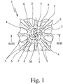
- Fig. 1 is a schematic plan view of a proposed swirl nozzle 1 according to a first embodiment, without a cover.
- the swirl nozzle 1 has at least one inlet channel 2, preferably several and in particular two to twelve inlet channels 2. In the embodiment shown, four inlet channels 2 are provided.
- the swirl nozzle 1 also has an outlet channel 3 which in the drawing shown in Fig. 1 extends transversely - i.e. at least at an angle and especially perpendicularly - to the plane of the drawing.
- the inlet channels 2 extend in the plane of the drawing in the embodiment shown, thus in a common plane, in particular. Accordingly, the outlet channel 3 extends transversely (at an angle or slope), especially perpendicularly, to the inlet channels 2 or vice versa.
- the inlet channels 2 may also extend over a different surface, e.g. a cone surface.
- the inlet channels 2 preferably open directly, radially and/or tangentially into the outlet channel 3, but the inlet channels 2 may also open into the outlet channel 3 at an angle between tangentially and radially, preferably more tangentially, particularly preferably in an angular range of 25° starting from the tangential.
- no (additional) vortex chamber is provided as is conventional in the prior art.
- the swirl nozzle 1 may also have further structures upstream of the inlet channels 2; these therefore do not have to form an external inlet for the swirl nozzle 1 but are simply supply lines to the outlet channel 3.
- the swirl nozzle 1 serves to deliver and, in particular, atomise a fluid, such as a liquid (not shown), particularly a medicament formulation or the like.
- a fluid such as a liquid (not shown), particularly a medicament formulation or the like.
- the liquid is preferably supplied exclusively through the inlet channels 2 to the outlet channel, so that a vortex or turbulence is formed directly in the outlet channel 3.
- the liquid is preferably expelled only through the outlet channel 3 - in particular without any subsequent lines, channels or the like - and is atomised at this time or immediately afterwards into an aerosol (not shown) or fine droplets or particles.
- the inlets of the inlet channels 2 are preferably at a spacing of preferably 50 to 300 ⁇ m, especially 90 to 120 ⁇ m, from the central axis M of the outlet channel 3.
- the inlets are uniformly arranged in a circle around the outlet channel 3 or its central axis M.
- the inlet channels 2 extend towards the outlet channel 3 essentially in a radial or curved configuration, preferably with a curvature that is constant or that increases continuously towards the outlet channel 3, and/or with a decreasing channel cross-section.
- the direction of curvature of the inlet channels 2 corresponds to the direction of swirl of the swirl nozzle 1 or of the liquid (not shown) in the outlet channel 3.
- the inlet channels 2 preferably all become narrower towards the outlet channel 3, in particular by at least a factor 2 based on the cross-sectional area through which fluid can flow.
- the inlet channels 2 are preferably formed as depressions, particularly between guide means, partition walls, elevated sections 4 or the like.
- the inlet channels 2 or the elevated sections 4 which form or define them are at least substantially crescent-shaped or half moon-shaped.
- the depth of the inlet channels 2 is preferably 5 to 35 ⁇ m in each case.
- the outlets of the inlet channels 2 preferably each have a width of from 2 to 30 ⁇ m, particularly 10 to 20 ⁇ m.
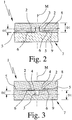
- the outlets of the inlet channels 2 are preferably each at a spacing from the central axis M of the outlet channel 3 which corresponds to 1.1 to 1.5 times the diameter of the outlet channel 3 and/or at least 1 ⁇ m. It can be inferred from the schematic sections shown in Figs 2 and 3 that the outlet channel 3 may be somewhat enlarged in cross-section or diameter in its inlet region which is radially bounded or formed by the outlets of the inlet channels 2 or end regions of the elevated sections 4. This enlargement is primarily caused by the manufacturing technique and is preferably small enough not to be hydraulically relevant. This possible radial offset is thus insignificant and the inlet channels 2 still open directly into the outlet channel 3. The enlargement of the diameter is preferably at most 30 ⁇ m, particularly only 10 ⁇ m or less. The transition from the enlargement to the remainder of the outlet channel 3 may be stepped or possibly conical.
- the outlet channel 3 is preferably at least substantially cylindrical. This is true in particular of the above-mentioned inlet region as well.
- the outlet channel 3 preferably has an at least substantially constant cross-section. The entire (slight) enlargement in the inlet region is not regarded as essential in this sense. However, it is also possible for the outlet channel 3 to have a slight conicity over its length and/or in the inlet region or outlet region, caused particularly by the manufacturing method.
- the diameter of the outlet channel 3 is preferably 5 to 100 ⁇ m, in particular 25 to 45 ⁇ m.
- the length of the outlet channel 3 is preferably 10 to 100 ⁇ m, particularly 25 to 45 ⁇ m, and/or preferably corresponds to 0.5 to 2 times the diameter of the outlet channel 3.
- the swirl nozzle 1 preferably comprises, upstream of the inlet channels 2, a filter structure which in the embodiment shown is formed by elevated sections 5 and in particular comprises smaller cross-sections of passage than the inlet channels 2.
- the filter structure which is shown not to scale in Fig. 1 , prevents particles from entering the inlet channels 2, which could block the inlet channels 2 and/or the outlet channel 3. Such particles are filtered out by the filter structure because of the smaller cross-sections of passage.
- the filter structure may also be formed independently of the preferred construction of the swirl nozzle 1 as described hereinbefore in other swirl nozzles.
- the filter structure has a plurality of parallel flow channels with the smaller cross-section and therefore preferably substantially more flow paths than inlet channels 2 are provided, with the result that the flow resistance of the filter structure is preferably less than the flow resistance of the parallel inlet channels 2. This also ensures satisfactory operation even when individual flow paths of the filter structure are blocked by particles, for example.
- the inlet channels 2 are attached at the inlet end to a common supply channel 6 which serves to distribute and supply the liquid which is to be atomised.
- the supply channel 6 is preferably annular (cf. Fig. 1 ) and peripherally surrounds the inlet channels 2.
- the supply channel 6 is arranged radially between the filter structure or the elevated sections 5 on the one hand and the inlet channels 2 or elevated sections 4 on the other hand. The supply channel 6 ensures, in particular, that all the inlet channels 2 are adequately supplied with the liquid which is to be atomised, for example even when the liquid is supplied only from one side as shown in Figure 1 or if the filter structure is partly blocked.
- the inlet channels 2 and the outlet channel 3 - preferably also the common supply channel 6 and/or the filter structure - are preferably formed in a one-piece or multi-part nozzle body 7. Two proposed methods and embodiments are described more fully hereinafter.
- the nozzle body 7 is made in two parts in the first embodiment. It comprises a first, preferably plate-like component 8 and a second, preferably also plate-like component 9.
- Fig. 1 shows only the first component 8, i.e. the swirl nozzle 1 without the second component 9 which forms a cover.
- Fig. 2 shows, in schematic section on the line II-II of Fig. 1 , the swirl nozzle 1 with the two components 8 and 9 in the not yet completely finished state.
- first of all the desired structures are formed at least partly and, in particular, at least substantially completely in the first component 8 starting from a flat side, particularly by etching, as described for example in the prior art mentioned hereinbefore.
- at least one inlet channel 2 and preferably all the inlet channels 2 and the outlet channel 3 are recessed in the first component 8 starting from the flat side, and more particularly are formed as depressions by etching.
- the inlet channels 2 extend in particular parallel to the flat side.
- the outlet channel 3 extends in particular at right-angles to the flat side and is initially recessed or formed only as a recess closed at one end (blind bore).
- all the other desired structures or the like can be simultaneously formed in the first component 8, especially the common supply channel 6, the filter structure and/or other feed lines or the like.
- the first component 8 preferably consists of silicon or some other suitable material.
- first component 8 is joined to the second component 9, so that the second component 9 at least partially covers the flat side of the first component 8 comprising the inlet channel 2 or inlet channels 2, so as to form the desired sealed hollow structures of the swirl nozzle 1.
- the components 8 and 9 are joined together in particular by so-called bonding or welding. However, theoretically any other suitable method of attachment or a sandwich construction is possible.
- a plate member (not shown), particularly a silicon wafer is used, from which a plurality of first components 8 are used for a plurality of swirl nozzles 1.
- the structures, especially depressions or recesses are initially produced starting from a flat side of the plate member for the plurality of first components 8 or swirl nozzles 1. This is done in particular by a treatment or etching of fine structures as is conventional in semiconductor manufacture, and consequently reference is hereby made in this respect to the prior art relating to the etching of silicon or the like.
- the second component 9, like the first component 8 is made from a plate member which is broken down or separated into a plurality of second components 9.
- a silicon wafer as the plate member, as explained above.
- the plate member used to produce the second components 9 may also be a silicon wafer or some other kind of wafer, a sheet of glass or the like.
- a plate member is used to produce both the first components 8 and the second components 9, it is particularly preferable to join the plate members together before they are broken down into the individual components 8 and 9. This makes assembly and positioning substantially easier.
- plate members of the same size and shape. If for example a disc-shaped silicon wafer is used to form the first components 8, it is recommended to use a disc-shaped plate member of the same size, e.g. made of glass, to form the second components 9. Obviously, other plate shapes may be used and joined together, such as rectangular plate members, for example. Circular discs are particularly recommended, however, as wafers of silicon or other materials are obtainable particularly cheaply. It should be noted that the plate members which are joined together may if required be of different shapes or sizes.
- the first component 8 or the corresponding plate member is machined , particularly ground away on the flat side remote from the second component 9 or the plate member thereof.
- the thickness of the first component 8 is substantially reduced.
- the initial thickness D1 is usually about 600 to 700 ⁇ m.
- This thickness D1 is substantially reduced, for example to a thickness D2 of about 150 ⁇ m or less.
- the method of manufacture described above makes it easy to produce the first component 8 very thinly and at the same time achieve very high stability and resistance for the swirl nozzle 1, particularly to high fluid pressures, as the second component 9 forms a unified whole with the first component 8 and ensures the required stability or stabilisation of the first component 8, even when it is very thin.
- the fact that there is preferably no vortex chamber between the inlet channels 2 and the outlet channel 3 also contributes to the high stability or load-bearing capacity of the first component 8, even when it has a very low thickness D2.
- the elevated sections 4 or other webs or the like which delimit or define the inlet channels 2 may extend directly to the outlet channel 3, which has a substantially smaller diameter than a normal vortex chamber. Accordingly, the section of the first component 8 which is unsupported in this region is essentially reduced to the diameter of the outlet channel 3.
- the plate members joined together are finally broken down into the preferably rectangular or square or optionally round components 8 and 9, respectively, i.e. into the finished swirl nozzles, particularly by sawing or other machining.
- FIG. 3 shows, in a section on the line III-IV in Fig. 1 , corresponding to Fig. 2 , the swirl nozzle 1 according to the second embodiment. Only major differences between the second embodiment and the first embodiment will be described hereinafter. In other respects the foregoing remarks continue to apply accordingly or in supplementary manner.
- the outlet channel 3 is formed at least partially, particularly at least essentially, in the second component 9.
- the remainder of the structure of the swirl nozzle 1, particularly at least one inlet channel 2, is formed in the first component 8. Consequently it is possible to produce the outlet channel 3 at least largely independently of the manufacture of the remaining structure of the swirl nozzle 1, particularly the inlet region of the swirl nozzle 1.
- the outlet channel 3 is at least partly recessed in the second component 9, starting from a flat side and extending in particular at right-angles to the flat side, in the form of a recess, preferably by etching.
- the outlet channel 3 is recessed initially only on one side, particularly by etching, in the second component 9 while it is open, before the two components 8 and 9 are joined together, i.e. as a blind bore as in the first embodiment, but in this case in the second component 9 and not in the first component 8.
- the surfaces can then be ground, polished or otherwise thinned, e.g. by spin etching.
- the two components 8 and 9 are joined together.
- this is done by joining together the plate members, each of which forms a plurality of components 8 or 9.
- the second component 9 or the plate member forming the second components 9 is then thinned, particularly ground, on the flat side remote from the first component 8. This causes the outlet channel 3 or outlet channels 3 to be opened up from the machining side.
- the machining and/or opening may, however, also be carried out before the components are joined together.
- the thinning of the second component 9 or of the corresponding plate member is preferably done to a thickness D2 as explained in the first embodiment, with the result that the remarks made previously apply here.
- silicon is preferably used for the second component 9 as well.
- a silicon wafer or the like is used as a plate member for forming the second components 9.
- the proposed manufacturing methods described are not restricted to the manufacture of the swirl nozzle 1 proposed or shown but may also be used generally for other swirl nozzles 1 and also for vortex chamber nozzles, i.e. swirl nozzles with vortex chambers.
- etching is preferably used to work on the material, particularly to thin it. In this way very precise very fine structures can be obtained, particularly recesses, channels and the like, most preferably in the ⁇ m range of 50 ⁇ m, particularly 30 ⁇ m or less.
- other methods of machining material and/or shaping such as laser treatment, mechanical treatment, casting and/or embossing may also be used.
- the swirl nozzle 1 is at least substantially flat and/or plate-shaped.
- the main direction of flow or the main supply direction of the liquid (not shown) runs essentially in the main direction of extent, corresponding in particular to the planes of the plates of the components 8, 9 or the joined-together surfaces of the components 8, 9 or a plane parallel thereto.
- the outlet channel 3 preferably extends transversely, especially perpendicularly, to the main plane of extent or plane of the plate of the spray nozzle 1, to the main inflow direction of the liquid and/or to the main extent of the filter structure.
- the main direction of extent of the outlet channel 3 and the main direction of delivery of the swirl nozzle 1 preferably extend in the direction of the central axis M.
- the inlet channels 2, the supply channel 6, the filter structure and/or other inflow regions for the liquid formed in the swirl nozzle 1 are preferably at least substantially arranged in a common plane and most preferably are formed only on one side, in particular, starting from a flat side or surface of the component 8.
- a plurality of outlet channels 3 or even a plurality of swirl nozzles 1 may be formed on a component 8, 9.
- the structures are then adapted accordingly.
- Fig. 4 shows, in a view corresponding to Fig. 1 , a swirl nozzle arrangement according to a third embodiment having several, in this case three, swirl nozzles 1 and a common filter structure 5 on a component 8 and/or 9.
- the foregoing remarks and explanations apply accordingly or in supplementary manner.
- the proposed swirl nozzle 1 is most preferably used to atomise a liquid medicament formulation, the medicament formulation being passed through the swirl nozzle 1 under high pressure, so that the medicament formulation emerging from the outlet channel 3 is atomised into an aerosol (not shown), more particularly having particles or droplets with a mean diameter of less than 10 ⁇ m, preferably 1 to 7 ⁇ m, particularly substantially 5 ⁇ m or less.
- the proposed swirl nozzle 1 is used in an atomiser 10 which will be described hereinafter.
- the swirl nozzle 1 serves to achieve very good or fine atomising while at the same time achieving a relatively large flow volume and/or at relatively low pressure.
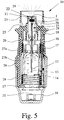
- Figs. 5 and 6 show a diagrammatic view of the atomiser 10 in the non-tensioned state ( Fig. 5 ) and in the tensioned state ( Fig. 6 ).
- the atomiser 10 is constructed in particular as a portable inhaler and preferably operates without propellant gas.
- the swirl nozzle 1 is preferably installed in the atomiser 10, particularly a holder 11. Thus, a nozzle arrangement 22 is obtained.
- the atomiser 10 is used to atomise a fluid 12, particularly a highly effective medicament, a medicament formulation or the like.
- a fluid 12 which is preferably a liquid, especially a medicament
- an aerosol 24 is formed which can be breathed in or inhaled by a user (not shown).
- the inhalation is carried out at least once a day, more particularly several times a day, preferably at prescribed intervals, depending on the patient's condition.
- the known atomiser 10 has an insertable and preferably replaceable container 13 containing the fluid 12.
- the container 13 thus constitutes a reservoir for the fluid 2 which is to be atomised.
- the container 13 contains a sufficient quantity of fluid 12 or active substance to be able to provide up to 300 dosage units, for example, i.e. up to 300 sprays or applications.
- the container 13 is substantially cylindrical or cartridge-like and can be inserted in the atomiser 10 from below, after the atomiser has been opened, and can optionally be replaced.
- the container is of rigid construction, the fluid 12 preferably being held in a fluid chamber 14 in the container 13, consisting of a collapsible bag.
- the atomiser 10 also comprises a conveying device, preferably a pressure generator 15 for conveying and atomising the fluid 12, particularly in a predetermined, optionally adjustable metered dosage.
- a conveying device preferably a pressure generator 15 for conveying and atomising the fluid 12, particularly in a predetermined, optionally adjustable metered dosage.
- the atomiser 10 or pressure generator 15 has a holding device 16 for the container 13, an associated drive spring 17, which is shown only in part, having a locking element 18 which can be manually operated to release it, a conveying tube 19 preferably in the form of a thick-walled capillary with an optional valve, particularly a non-return valve 20, a pressure chamber 21 and the nozzle arrangement 22 in the region of a mouthpiece 23.
- the container 13 is fixed in the atomiser 10 by means of the holding device 16, more particularly by engagement, such that the conveying tube 19 is immersed in the container 13.
- the holding device 16 may be constructed so that the container 13 can be released and replaced.
- the fluid 12 in the pressure chamber 21 is put under pressure, by moving the conveying tube 19 with its now closed non-return valve 20 upwards again by releasing the drive spring 17 and it now acts as a pressure ram or piston. This pressure forces the fluid 12 out through the nozzle 22, where it is atomised into an aerosol 24, as shown in Fig. 10.
- a user or patient can inhale the aerosol 24, while a supply of air can preferably be sucked into the mouthpiece 23 through at least one air inlet opening 25.
- the atomiser 10 has an upper housing part 26 and an inner part 27 which is rotatable relative to it ( Fig. 6 ), having an upper part 27a and a lower part 27b ( Fig. 5 ), while a housing part 28 which is, in particular, manually operated is releasably attached, preferably pushed onto, the inner part 27, preferably by means of a holding element 29.
- the housing part 28 can be detached from the atomiser 10.
- the housing part 28 can be rotated relative to the upper housing part 26, carrying with it the lower part 27b of the inner part 27 which is lower down in the drawing.
- the drive spring 17 is tensioned in the axial direction by means of a gear (not shown) acting on the holding device 16.
- a gear not shown
- the container 13 is moved axially downwards until the container 13 assumes an end position as shown in Fig. 12.
- the drive spring 17 is under tension.
- an axially acting spring 30 disposed in the housing part 28 comes to abut on the base of the container and by means of a piercing element 31 pierces the container 13 or a seal at the bottom when it first comes into abutment therewith, for venting.
- the container 13 is moved back into its original position shown in Fig. 5 by the drive spring 17, while the conveying tube 19 is moved into the pressure chamber 21.
- the container 13 and the conveying element or conveying tube 19 thus execute a lifting movement during the tensioning process or for drawing up the fluid and during the atomising process.
- the container 13 can preferably be inserted into the atomiser 10, i.e. can be installed therein. Consequently, the container 13 is preferably a separate component.
- the container 13 or fluid chamber 14 may theoretically also be formed directly by the atomiser 10 or part of the atomiser 10 or in some other way integrated in the atomiser 10 or may be connectable thereto.
- the proposed atomiser 10 is preferably constructed to be portable and/or manually operated and in particular it is a movable hand-held device.
- the atomiser 10 is constructed as an inhaler, especially for medicinal aerosol treatment.
- the atomiser 10 may also be designed for other purposes, and may preferably be used to atomise a cosmetic liquid and particularly as a perfume atomiser.
- the container 13 accordingly contains, for example, a medicament formulation or a cosmetic liquid such as perfume or the like.
- the proposed solution may be used not only in the atomiser 10 specifically described here but also in other atomisers or inhalers, e.g. powder inhalers or so-called metered dose inhalers.
- the atomising of the fluid 12 through the swirl nozzle 1 is preferably carried out at a pressure of about 0.1 to 35 MPa, in particular about 0.5 to 20 MPa, and/or with a flow volume of about 1 to 300 ⁇ l/s, in particular about 5 to 50 ⁇ l/s.
Description
- The present invention relates to a swirl nozzle, particularly for delivering or atomising a liquid, preferably a medicament formulation or other fluid, according to the preamble of
claim 1, a use of the swirl nozzle for atomising a liquid medicament formulation and methods of producing a swirl nozzle and an atomiser comprising a swirl nozzle. - When atomising a liquid medicament formulation the intention is to convert as precisely defined an amount of active substance as possible into an aerosol for inhalation. The aerosol should be characterised by a low mean value for the droplet size, while having a narrow droplet size distribution and a low pulse (low propagation rate).
- The term "medicament formulation" according to the present invention extends beyond medicaments to include therapeutic agents or the like, particularly every kind of agent for inhalation or other use. However, the present invention is not restricted to the atomising of agents for inhalation but may also be used in particular for cosmetic agents, agents for body or beauty care, agents for household use, such as air fresheners, polishes or the like, cleaning agents or agents for other purposes, particularly for delivering small amounts, although the description that follows is primarily directed to the preferred atomisation of a medicament formulation for inhalation.
- The term "liquid" is to be understood in a broad sense and includes, in particular, dispersions, suspensions, so-called suslutions (mixtures of solutions and suspensions) or the like. The present invention can also be generally used for other fluids. However, the description that follows is directed primarily to the delivery of liquid.
- By the term "aerosol" is meant, according to the present invention, a preferably cloud-like accumulation of a plurality of drops of the atomised liquid with preferably substantially undirected or wide spatial distribution of the directions of movement and preferably with drops travelling at low speeds, but it may also be, for example, a conical cloud of droplets with a primary direction corresponding to the main exit direction or exit pulse direction.
-
US 5,435,884 A ,US 5,951,882 A andEP 0 970 751 B1 are directed to the manufacture of nozzles for vortex chambers. A flat, key-shaped vortex chamber is etched into a plate-shaped piece of material, or component, together with inlet channels opening tangentially into the vortex chamber, starting from a flat side. In addition, an outlet channel is etched through the thin base of the vortex chamber in the centre thereof. The inlet channels are connected at the inlet end to an annular supply channel which is also etched into the component. The component with this etched structure is covered by an inlet piece and installed in a carrier. These vortex chamber nozzles are not ideal for higher pressures and for delivering small amounts or for producing very fine droplets. -
WO 02/070141 A1 -
EP 0412524 A1 discloses a disposable nozzle adapter for intranasal administration of a viscous medical solution, the adapter comprising a nozzle tip which has a top wall and a cylindrical portion extending therefrom. The top wall has a central spray opening including a tapered recess and swirl grooves extending out-wardls from the tapered recess to the inner surface of the cylindrical portion. The swirl grooves have a cross-sectional area which increases outwardly. The nozzle tip is fitted into a cylindrical body and engaged with a rod arranged therein so that an annular channel communicating with the grooves is formed. -
EP 0860210 A2 discloses a form of nozzle assembly for use in generating sprays from a fluid, the nozzle comprising a first member having structures (one or more nozzle outlets, fluid inlets and channels connecting them) formed by a electrical or chemical etching process which selectively removes material from one face of said member. A second member cooperating with the first member provides a wall of the outlets, inlets or channels to form fluid flow paths for the nozzle assembly. Various nozzle designs are shown, including a design with a vortex generating structure fitted into a nozzle outlet. - The objective of the present invention is to provide a swirl nozzle, a use of a swirl nozzle and methods of producing swirl nozzles and an atomiser, so as to enable simple nozzle construction and/or ease of manufacture, while still allowing very small amounts of liquid to be delivered and/or very fine atomising to be achieved, in particular.
- This objective is achieved by means of a swirl nozzle according to
claim 1, a use according toclaim 16, a method according toclaim 18 or an atomiser according toclaim 21. Advantageous further features are recited in the subsidiary claims. - According to a first aspect, which is not claimed, the inlet channels open directly and/or tangentially or at an angle between tangentially and radially into the outlet channel. The vortex chamber used in the prior art is not required. This makes the construction particularly compact and simple. In addition it allows a more robust structure which will withstand higher pressures, in particular, as there is no longer any need for a vortex chamber with a base which is thin so as to ensure a short length of outlet channel. Instead, it is possible to improve the reinforcement of the material and the support around the outlet channel.
- By dispensing with a vortex chamber the volume of liquid to be received by the nozzle is reduced substantially. This is advantageous for example when delivering medicament formulations if very small amounts have to be metered very accurately. Moreover, the smallest possible volumes in the swirl nozzle are advantageous, for example, in order to counteract possible bacterial growth in the medicament formulation in the swirl nozzle and/or contamination of the swirl nozzle caused by the precipitation of solids.
- In order to atomise a liquid medicament formulation the medicament formulation is passed through the proposed swirl nozzle under high pressure, so that the medicament formulation is atomised into an aerosol or a fine spray mist, more particularly immediately on leaving the outlet channel. The resultant cloud is released in a substantially conical shape, in particular.
- According to an aspect of the present invention, which is defined by the appended claims, the spray nozzle comprises, upstream of the inlet channels, a filter structure having smaller cross-sections of passage than the inlet channels. This again allows a very small and in particular microfine construction of the swirl nozzle and permits very fine atomisation even with small amounts of liquid, as any particles contained in the liquid which is to be atomised and which would otherwise be liable to block the inlet channels or even the outlet channel can be filtered out. Accordingly, high operational reliability is achieved even with a swirl nozzle of very small dimensions.
- A first proposed method of producing a swirl nozzle is characterised in that at least one inlet channel is formed on a flat side of a first plate-shaped component and an outlet channel is formed which extends into the component and is initially still closed off at one end. Then the first component is connected to a second, preferably also plate-shaped component, so that the second component at least partially covers the flat side of the first channel section containing the inlet channel. Only when the two pieces of material have been joined together is the first component machined, particularly ground away on the flat side remote from the second component, thereby opening up the outlet channel on this side. The second component stabilises the first component during the machining and thereafter. This provides a simple manner of producing relatively thin or small structures, particularly a short outlet channel, with high stability, while also obtaining a swirl nozzle which is resistant to high fluid pressures or other stresses.
- A second proposed method of producing a swirl nozzle is characterised in that at least one inlet channel is formed in a first, preferably plate-shaped component starting from a flat side, in that the outlet channel is at least partially formed in a second, preferably plate-shaped component, starting from a flat side and in particular extending transversely thereof, and the two pieces of material are joined together, so that the second component at least partially covers the flat side of the first component comprising the inlet channel. This provides a simple way of manufacturing even very fine structures. The manufacture of the at least one inlet channel and of the outlet channel independently of one another makes it possible to optimise the manufacturing processes involved.
- According to a preferred further feature, the outlet channel is formed, particularly by etching, on only one side of the second component, while open, before the pieces of material are joined together. Then the two pieces of material are joined together for the first time so that the opening of the outlet channel faces towards the first component. Only then is the second component machined, particularly ground away, on the flat side remote from the component, thereby opening up the outlet channel on this side. The first component may accordingly stabilise the second component even during the machining and thereafter.
- Further aspects, features, properties and advantages of the present, which is defined by the appended claims, will become apparent from the claims and the following description. Specifically:
- Fig. 1
- is a schematic view of a proposed swirl nozzle according to a first embodiment;
- Fig. 2
- is a schematic section through the swirl nozzle according to
Figure 1 ; - Fig. 3
- is a schematic section through a proposed swirl nozzle corresponding to
Fig. 2 , in a second embodiment; - Fig. 4
- is a schematic view of a proposed swirl nozzle arrangement, corresponding to
Fig. 1 , according to a third embodiment; - Fig. 5
- is a schematic section through an atomiser in the non-tensioned stated with the proposed swirl nozzle; and
- Fig. 6
- is a schematic section through the atomiser in the tensioned state, rotated through 90° compared with
Fig. 5 . - In the Figures, the same reference numerals have been used for identical or similar parts, even though the corresponding description may be omitted.
-
Fig. 1 is a schematic plan view of a proposedswirl nozzle 1 according to a first embodiment, without a cover. Theswirl nozzle 1 has at least oneinlet channel 2, preferably several and in particular two to twelveinlet channels 2. In the embodiment shown, fourinlet channels 2 are provided. - The
swirl nozzle 1 also has anoutlet channel 3 which in the drawing shown inFig. 1 extends transversely - i.e. at least at an angle and especially perpendicularly - to the plane of the drawing. Theinlet channels 2 extend in the plane of the drawing in the embodiment shown, thus in a common plane, in particular. Accordingly, theoutlet channel 3 extends transversely (at an angle or slope), especially perpendicularly, to theinlet channels 2 or vice versa. Theinlet channels 2 may also extend over a different surface, e.g. a cone surface. - It is proposed that the
inlet channels 2 preferably open directly, radially and/or tangentially into theoutlet channel 3, but theinlet channels 2 may also open into theoutlet channel 3 at an angle between tangentially and radially, preferably more tangentially, particularly preferably in an angular range of 25° starting from the tangential. Thus, in particular, no (additional) vortex chamber is provided as is conventional in the prior art. This allows the structure of theswirl nozzle 1 to be kept simple, compact and particularly robust, as will become apparent from the description to follow. Theswirl nozzle 1 may also have further structures upstream of theinlet channels 2; these therefore do not have to form an external inlet for theswirl nozzle 1 but are simply supply lines to theoutlet channel 3. - The
swirl nozzle 1 serves to deliver and, in particular, atomise a fluid, such as a liquid (not shown), particularly a medicament formulation or the like. With the structure or arrangement shown inFig. 1 suitably covered, the liquid is preferably supplied exclusively through theinlet channels 2 to the outlet channel, so that a vortex or turbulence is formed directly in theoutlet channel 3. The liquid is preferably expelled only through the outlet channel 3 - in particular without any subsequent lines, channels or the like - and is atomised at this time or immediately afterwards into an aerosol (not shown) or fine droplets or particles. - The inlets of the
inlet channels 2 are preferably at a spacing of preferably 50 to 300 µm, especially 90 to 120 µm, from the central axis M of theoutlet channel 3. In particular, the inlets are uniformly arranged in a circle around theoutlet channel 3 or its central axis M. - The
inlet channels 2 extend towards theoutlet channel 3 essentially in a radial or curved configuration, preferably with a curvature that is constant or that increases continuously towards theoutlet channel 3, and/or with a decreasing channel cross-section. The direction of curvature of theinlet channels 2 corresponds to the direction of swirl of theswirl nozzle 1 or of the liquid (not shown) in theoutlet channel 3. - Particularly preferably, the
inlet channels 2 are curved at least substantially according to the following formula, which gives the shape of the sidewalls of theinlet channels 2 in polar coordinates (r = radius, W = angle):
inlet channel 2 in question and WA and WE are the corresponding angles. - The
inlet channels 2 preferably all become narrower towards theoutlet channel 3, in particular by at least afactor 2 based on the cross-sectional area through which fluid can flow. - The
inlet channels 2 are preferably formed as depressions, particularly between guide means, partition walls,elevated sections 4 or the like. In the embodiment shown theinlet channels 2 or theelevated sections 4 which form or define them are at least substantially crescent-shaped or half moon-shaped. - The depth of the
inlet channels 2 is preferably 5 to 35µm in each case. The outlets of theinlet channels 2 preferably each have a width of from 2 to 30 µm, particularly 10 to 20 µm. - The outlets of the
inlet channels 2 are preferably each at a spacing from the central axis M of theoutlet channel 3 which corresponds to 1.1 to 1.5 times the diameter of theoutlet channel 3 and/or at least 1 µm. It can be inferred from the schematic sections shown inFigs 2 and 3 that theoutlet channel 3 may be somewhat enlarged in cross-section or diameter in its inlet region which is radially bounded or formed by the outlets of theinlet channels 2 or end regions of theelevated sections 4. This enlargement is primarily caused by the manufacturing technique and is preferably small enough not to be hydraulically relevant. This possible radial offset is thus insignificant and theinlet channels 2 still open directly into theoutlet channel 3. The enlargement of the diameter is preferably at most 30 µm, particularly only 10 µm or less. The transition from the enlargement to the remainder of theoutlet channel 3 may be stepped or possibly conical. - The
outlet channel 3 is preferably at least substantially cylindrical. This is true in particular of the above-mentioned inlet region as well. Theoutlet channel 3 preferably has an at least substantially constant cross-section. The entire (slight) enlargement in the inlet region is not regarded as essential in this sense. However, it is also possible for theoutlet channel 3 to have a slight conicity over its length and/or in the inlet region or outlet region, caused particularly by the manufacturing method. - The diameter of the
outlet channel 3 is preferably 5 to 100 µm, in particular 25 to 45 µm. The length of theoutlet channel 3 is preferably 10 to 100 µm, particularly 25 to 45 µm, and/or preferably corresponds to 0.5 to 2 times the diameter of theoutlet channel 3. - The
swirl nozzle 1 preferably comprises, upstream of theinlet channels 2, a filter structure which in the embodiment shown is formed byelevated sections 5 and in particular comprises smaller cross-sections of passage than theinlet channels 2. The filter structure, which is shown not to scale inFig. 1 , prevents particles from entering theinlet channels 2, which could block theinlet channels 2 and/or theoutlet channel 3. Such particles are filtered out by the filter structure because of the smaller cross-sections of passage. The filter structure may also be formed independently of the preferred construction of theswirl nozzle 1 as described hereinbefore in other swirl nozzles. - With regard to the filter structure it should be pointed out that it has a plurality of parallel flow channels with the smaller cross-section and therefore preferably substantially more flow paths than
inlet channels 2 are provided, with the result that the flow resistance of the filter structure is preferably less than the flow resistance of theparallel inlet channels 2. This also ensures satisfactory operation even when individual flow paths of the filter structure are blocked by particles, for example. - The
inlet channels 2 are attached at the inlet end to acommon supply channel 6 which serves to distribute and supply the liquid which is to be atomised. In the embodiment shown thesupply channel 6 is preferably annular (cf.Fig. 1 ) and peripherally surrounds theinlet channels 2. In particular, thesupply channel 6 is arranged radially between the filter structure or theelevated sections 5 on the one hand and theinlet channels 2 orelevated sections 4 on the other hand. Thesupply channel 6 ensures, in particular, that all theinlet channels 2 are adequately supplied with the liquid which is to be atomised, for example even when the liquid is supplied only from one side as shown inFigure 1 or if the filter structure is partly blocked. - The preferred production of the proposed
swirl nozzle 1 described above will now be explained in more detail. However, the manufacturing methods described may theoretically also be used with other swirl nozzles, possibly even ones provided with a vortex chamber. - The
inlet channels 2 and the outlet channel 3 - preferably also thecommon supply channel 6 and/or the filter structure - are preferably formed in a one-piece ormulti-part nozzle body 7. Two proposed methods and embodiments are described more fully hereinafter. - The
nozzle body 7 is made in two parts in the first embodiment. It comprises a first, preferably plate-like component 8 and a second, preferably also plate-like component 9. -
Fig. 1 shows only thefirst component 8, i.e. theswirl nozzle 1 without the second component 9 which forms a cover.Fig. 2 shows, in schematic section on the line II-II ofFig. 1 , theswirl nozzle 1 with the twocomponents 8 and 9 in the not yet completely finished state. - In the first embodiment, first of all the desired structures are formed at least partly and, in particular, at least substantially completely in the
first component 8 starting from a flat side, particularly by etching, as described for example in the prior art mentioned hereinbefore. In particular, at least oneinlet channel 2 and preferably all theinlet channels 2 and theoutlet channel 3 are recessed in thefirst component 8 starting from the flat side, and more particularly are formed as depressions by etching. Theinlet channels 2 extend in particular parallel to the flat side. Theoutlet channel 3 extends in particular at right-angles to the flat side and is initially recessed or formed only as a recess closed at one end (blind bore). - In addition, all the other desired structures or the like can be simultaneously formed in the
first component 8, especially thecommon supply channel 6, the filter structure and/or other feed lines or the like. - The
first component 8 preferably consists of silicon or some other suitable material. - Then the
first component 8 is joined to the second component 9, so that the second component 9 at least partially covers the flat side of thefirst component 8 comprising theinlet channel 2 orinlet channels 2, so as to form the desired sealed hollow structures of theswirl nozzle 1. - The
components 8 and 9 are joined together in particular by so-called bonding or welding. However, theoretically any other suitable method of attachment or a sandwich construction is possible. - In a particularly preferred alternative embodiment a plate member (not shown), particularly a silicon wafer is used, from which a plurality of
first components 8 are used for a plurality ofswirl nozzles 1. Before being broken down intoindividual components 8 or swirlnozzles 1, preferably the structures, especially depressions or recesses, are initially produced starting from a flat side of the plate member for the plurality offirst components 8 or swirlnozzles 1. This is done in particular by a treatment or etching of fine structures as is conventional in semiconductor manufacture, and consequently reference is hereby made in this respect to the prior art relating to the etching of silicon or the like. - Particularly preferably, the second component 9, like the
first component 8, is made from a plate member which is broken down or separated into a plurality of second components 9. To produce thefirst components 8, it is particularly preferable to use a silicon wafer as the plate member, as explained above. The plate member used to produce the second components 9 may also be a silicon wafer or some other kind of wafer, a sheet of glass or the like. - If a plate member is used to produce both the
first components 8 and the second components 9, it is particularly preferable to join the plate members together before they are broken down into theindividual components 8 and 9. This makes assembly and positioning substantially easier. - In order to assist with the positioning of the plate members relative to one another, it is particularly preferable to use plate members of the same size and shape. If for example a disc-shaped silicon wafer is used to form the
first components 8, it is recommended to use a disc-shaped plate member of the same size, e.g. made of glass, to form the second components 9. Obviously, other plate shapes may be used and joined together, such as rectangular plate members, for example. Circular discs are particularly recommended, however, as wafers of silicon or other materials are obtainable particularly cheaply. It should be noted that the plate members which are joined together may if required be of different shapes or sizes. - After the two
components 8 and 9 or the plate members which form them have been joined together, either before or after the separation or breaking down of the plate members into theindividual components 8 and 9 or into theswirl nozzles 1, thefirst component 8 or the corresponding plate member is machined , particularly ground away on the flat side remote from the second component 9 or the plate member thereof. In this way the thickness of thefirst component 8 is substantially reduced. In a conventional silicon wafer the initial thickness D1 is usually about 600 to 700 µm. This thickness D1 is substantially reduced, for example to a thickness D2 of about 150 µm or less. This results in the opening up of theoutlet channels 3, which were initially closed on one side, from the machining side. The length of theoutlet channels 3 is thus determined by the thickness D2 to which thefirst component 8 or the plate member forming thecomponents 8 is machined. - The method of manufacture described above makes it easy to produce the
first component 8 very thinly and at the same time achieve very high stability and resistance for theswirl nozzle 1, particularly to high fluid pressures, as the second component 9 forms a unified whole with thefirst component 8 and ensures the required stability or stabilisation of thefirst component 8, even when it is very thin. - Moreover, the fact that there is preferably no vortex chamber between the
inlet channels 2 and theoutlet channel 3 also contributes to the high stability or load-bearing capacity of thefirst component 8, even when it has a very low thickness D2. Instead, theelevated sections 4 or other webs or the like which delimit or define theinlet channels 2 may extend directly to theoutlet channel 3, which has a substantially smaller diameter than a normal vortex chamber. Accordingly, the section of thefirst component 8 which is unsupported in this region is essentially reduced to the diameter of theoutlet channel 3. - The plate members joined together are finally broken down into the preferably rectangular or square or optionally
round components 8 and 9, respectively, i.e. into the finished swirl nozzles, particularly by sawing or other machining. - A second embodiment of the proposed
swirl nozzle 1 and a second embodiment of the preferred method of production will now be described with reference toFig. 3. Fig. 3 shows, in a section on the line III-IV inFig. 1 , corresponding toFig. 2 , theswirl nozzle 1 according to the second embodiment. Only major differences between the second embodiment and the first embodiment will be described hereinafter. In other respects the foregoing remarks continue to apply accordingly or in supplementary manner. - In the second embodiment the
outlet channel 3 is formed at least partially, particularly at least essentially, in the second component 9. The remainder of the structure of theswirl nozzle 1, particularly at least oneinlet channel 2, is formed in thefirst component 8. Consequently it is possible to produce theoutlet channel 3 at least largely independently of the manufacture of the remaining structure of theswirl nozzle 1, particularly the inlet region of theswirl nozzle 1. - In the second embodiment, before the two
components 8 and 9 are joined together, theoutlet channel 3 is at least partly recessed in the second component 9, starting from a flat side and extending in particular at right-angles to the flat side, in the form of a recess, preferably by etching. However, it is theoretically also possible to form or recess theoutlet channel 3 only after the twocomponents 8 and 9 have been joined together. - Particularly preferably, the
outlet channel 3 is recessed initially only on one side, particularly by etching, in the second component 9 while it is open, before the twocomponents 8 and 9 are joined together, i.e. as a blind bore as in the first embodiment, but in this case in the second component 9 and not in thefirst component 8. - Optionally, the surfaces can then be ground, polished or otherwise thinned, e.g. by spin etching. Then the two
components 8 and 9 are joined together. Preferably, once again, this is done by joining together the plate members, each of which forms a plurality ofcomponents 8 or 9. - Finally, the second component 9 or the plate member forming the second components 9 is then thinned, particularly ground, on the flat side remote from the
first component 8. This causes theoutlet channel 3 oroutlet channels 3 to be opened up from the machining side. The machining and/or opening may, however, also be carried out before the components are joined together. - The thinning of the second component 9 or of the corresponding plate member is preferably done to a thickness D2 as explained in the first embodiment, with the result that the remarks made previously apply here.
- In the second embodiment silicon is preferably used for the second component 9 as well. In particular, a silicon wafer or the like is used as a plate member for forming the second components 9.
- The proposed manufacturing methods described are not restricted to the manufacture of the
swirl nozzle 1 proposed or shown but may also be used generally forother swirl nozzles 1 and also for vortex chamber nozzles, i.e. swirl nozzles with vortex chambers. - During manufacture, etching is preferably used to work on the material, particularly to thin it. In this way very precise very fine structures can be obtained, particularly recesses, channels and the like, most preferably in the µm range of 50 µm, particularly 30 µm or less. However, in addition or alternatively, other methods of machining material and/or shaping, such as laser treatment, mechanical treatment, casting and/or embossing may also be used.
- Preferably, the
swirl nozzle 1 is at least substantially flat and/or plate-shaped. The main direction of flow or the main supply direction of the liquid (not shown) runs essentially in the main direction of extent, corresponding in particular to the planes of the plates of thecomponents 8, 9 or the joined-together surfaces of thecomponents 8, 9 or a plane parallel thereto. Theoutlet channel 3 preferably extends transversely, especially perpendicularly, to the main plane of extent or plane of the plate of thespray nozzle 1, to the main inflow direction of the liquid and/or to the main extent of the filter structure. The main direction of extent of theoutlet channel 3 and the main direction of delivery of theswirl nozzle 1 preferably extend in the direction of the central axis M. - The
inlet channels 2, thesupply channel 6, the filter structure and/or other inflow regions for the liquid formed in theswirl nozzle 1 are preferably at least substantially arranged in a common plane and most preferably are formed only on one side, in particular, starting from a flat side or surface of thecomponent 8. - Theoretically, a plurality of
outlet channels 3 or even a plurality ofswirl nozzles 1 may be formed on acomponent 8, 9. The structures are then adapted accordingly.Fig. 4 shows, in a view corresponding toFig. 1 , a swirl nozzle arrangement according to a third embodiment having several, in this case three,swirl nozzles 1 and acommon filter structure 5 on acomponent 8 and/or 9. The foregoing remarks and explanations apply accordingly or in supplementary manner. - Individual features and aspects of the various embodiments and of the claims may also be combined with one another as desired.
- The proposed
swirl nozzle 1 is most preferably used to atomise a liquid medicament formulation, the medicament formulation being passed through theswirl nozzle 1 under high pressure, so that the medicament formulation emerging from theoutlet channel 3 is atomised into an aerosol (not shown), more particularly having particles or droplets with a mean diameter of less than 10 µm, preferably 1 to 7 µm, particularly substantially 5 µm or less. - Preferably, the proposed
swirl nozzle 1 is used in anatomiser 10 which will be described hereinafter. In particular, theswirl nozzle 1 serves to achieve very good or fine atomising while at the same time achieving a relatively large flow volume and/or at relatively low pressure. -
Figs. 5 and6 show a diagrammatic view of theatomiser 10 in the non-tensioned state (Fig. 5 ) and in the tensioned state (Fig. 6 ). Theatomiser 10 is constructed in particular as a portable inhaler and preferably operates without propellant gas. - The
swirl nozzle 1 is preferably installed in theatomiser 10, particularly aholder 11. Thus, anozzle arrangement 22 is obtained. - The
atomiser 10 is used to atomise a fluid 12, particularly a highly effective medicament, a medicament formulation or the like. When thefluid 2, which is preferably a liquid, especially a medicament, is atomised, anaerosol 24 is formed which can be breathed in or inhaled by a user (not shown). Normally the inhalation is carried out at least once a day, more particularly several times a day, preferably at prescribed intervals, depending on the patient's condition. - The known
atomiser 10 has an insertable and preferablyreplaceable container 13 containing the fluid 12. Thecontainer 13 thus constitutes a reservoir for thefluid 2 which is to be atomised. Preferably, thecontainer 13 contains a sufficient quantity offluid 12 or active substance to be able to provide up to 300 dosage units, for example, i.e. up to 300 sprays or applications. - The
container 13 is substantially cylindrical or cartridge-like and can be inserted in theatomiser 10 from below, after the atomiser has been opened, and can optionally be replaced. The container is of rigid construction, the fluid 12 preferably being held in afluid chamber 14 in thecontainer 13, consisting of a collapsible bag. - The
atomiser 10 also comprises a conveying device, preferably apressure generator 15 for conveying and atomising the fluid 12, particularly in a predetermined, optionally adjustable metered dosage. - The
atomiser 10 orpressure generator 15 has a holdingdevice 16 for thecontainer 13, an associateddrive spring 17, which is shown only in part, having a lockingelement 18 which can be manually operated to release it, a conveyingtube 19 preferably in the form of a thick-walled capillary with an optional valve, particularly anon-return valve 20, apressure chamber 21 and thenozzle arrangement 22 in the region of amouthpiece 23. Thecontainer 13 is fixed in theatomiser 10 by means of the holdingdevice 16, more particularly by engagement, such that the conveyingtube 19 is immersed in thecontainer 13. The holdingdevice 16 may be constructed so that thecontainer 13 can be released and replaced. - During the axial tensioning of the
drive spring 17 the holdingdevice 16 is moved downwards in the drawings together with thecontainer 13 and conveyingtube 19, andfluid 12 is sucked out of thecontainer 13 through thenon-return valve 20 into thepressure chamber 21 of thepressure generator 15. - During the subsequent release after actuation of the locking
element 18, the fluid 12 in thepressure chamber 21 is put under pressure, by moving the conveyingtube 19 with its now closednon-return valve 20 upwards again by releasing thedrive spring 17 and it now acts as a pressure ram or piston. This pressure forces the fluid 12 out through thenozzle 22, where it is atomised into anaerosol 24, as shown in Fig. 10. - A user or patient (not shown) can inhale the
aerosol 24, while a supply of air can preferably be sucked into themouthpiece 23 through at least oneair inlet opening 25. - The
atomiser 10 has anupper housing part 26 and aninner part 27 which is rotatable relative to it (Fig. 6 ), having anupper part 27a and alower part 27b (Fig. 5 ), while ahousing part 28 which is, in particular, manually operated is releasably attached, preferably pushed onto, theinner part 27, preferably by means of a holdingelement 29. For inserting and/or exchanging thecontainer 13 thehousing part 28 can be detached from theatomiser 10. - The
housing part 28 can be rotated relative to theupper housing part 26, carrying with it thelower part 27b of theinner part 27 which is lower down in the drawing. As a result thedrive spring 17 is tensioned in the axial direction by means of a gear (not shown) acting on the holdingdevice 16. During tensioning thecontainer 13 is moved axially downwards until thecontainer 13 assumes an end position as shown in Fig. 12. In this state thedrive spring 17 is under tension. When the tensioning is carried out for the first time, anaxially acting spring 30 disposed in thehousing part 28 comes to abut on the base of the container and by means of a piercingelement 31 pierces thecontainer 13 or a seal at the bottom when it first comes into abutment therewith, for venting. During the atomising process thecontainer 13 is moved back into its original position shown inFig. 5 by thedrive spring 17, while the conveyingtube 19 is moved into thepressure chamber 21. Thecontainer 13 and the conveying element or conveyingtube 19 thus execute a lifting movement during the tensioning process or for drawing up the fluid and during the atomising process. - It should be mentioned in general that, in the proposed
atomiser 10, thecontainer 13 can preferably be inserted into theatomiser 10, i.e. can be installed therein. Consequently, thecontainer 13 is preferably a separate component. However, thecontainer 13 orfluid chamber 14 may theoretically also be formed directly by theatomiser 10 or part of theatomiser 10 or in some other way integrated in theatomiser 10 or may be connectable thereto. - By contrast with free-standing equipment or the like the proposed
atomiser 10 is preferably constructed to be portable and/or manually operated and in particular it is a movable hand-held device. - It is particularly preferable for atomisation to take place on each actuation for a period of about 1 to 2 breaths. However, theoretically, it is also possible for the atomisation to be longer-lasting or continuous.
- Particularly preferably, the
atomiser 10 is constructed as an inhaler, especially for medicinal aerosol treatment. Alternatively, however, theatomiser 10 may also be designed for other purposes, and may preferably be used to atomise a cosmetic liquid and particularly as a perfume atomiser. Thecontainer 13 accordingly contains, for example, a medicament formulation or a cosmetic liquid such as perfume or the like. - However, the proposed solution may be used not only in the
atomiser 10 specifically described here but also in other atomisers or inhalers, e.g. powder inhalers or so-called metered dose inhalers. - The atomising of the fluid 12 through the
swirl nozzle 1 is preferably carried out at a pressure of about 0.1 to 35 MPa, in particular about 0.5 to 20 MPa, and/or with a flow volume of about 1 to 300 µl/s, in particular about 5 to 50 µl/s. -
- 1
- swirl nozzle
- 2
- inlet channel
- 3
- outlet channel
- 4
- elevated section
- 5
- elevated section
- 6
- supply channel
- 7
- nozzle body
- 8
- component
- 9
- component
- 10
- atomiser
- 11
- holder
- 12
- fluid
- 13
- container
- 14
- fluid chamber
- 15
- pressure generator
- 16
- holding device
- 17
- drive spring
- 18
- locking element
- 19
- conveying tube
- 20
- non-return valve
- 21
- pressure chamber
- 22
- nozzle arrangement
- 23
- mouthpiece
- 24
- aerosol
- 25
- air inlet opening
- 26
- upper housing part
- 27
- inner part
- 27a
- upper part of 27
- 27b
- lower part of 27
- 28
- housing part
- 29
- holding element
- 30
- axially acting spring
- 31
- piercing element
- M
- central axis
Claims (22)
- Swirl nozzle (1) for atomising a medicament formulation in form of a fluid (12), the swirl nozzle (1) comprising inlet channels (2) and an outlet channel (3),
wherein the swirl nozzle (1) is at least substantially flat or plate-shaped in construction and wherein the inlet channels (2) extend transversely, especially perpendicularly, to the outlet channel (3),
characterised in
that the swirl nozzle (1) comprises, upstream of the inlet channels (2), a filter structure with smaller cross-sections of passage than the inlet channels (2), wherein the inlet channels (2) are attached at their inlet end to a common, preferably annular supply channel (6) and are surrounded thereby and
wherein the supply channel (6) is arranged radially between the filter structure and the inlet channels (2) and
wherein the inlet channels (2), the filter structure and supply channel (6) are located in a common plane. - Swirl nozzle according to claim 1, characterised in that the outlet channel (3) extends transversely, preferably perpendicularly, to the main plane of extent of the swirl nozzle (1), and/or the fluid (12) can be supplied to the outlet channel (3) exclusively through the inlet channels (2).
- Swirl nozzle according to one of the preceding claims, characterised in that the inlet channels (2) and the outlet channel (3) - preferably also the common supply channel (6) and/or the filter structure - are formed in a one-piece or multi-part nozzle body (7), particularly by etching, casting, embossing, laser processing and/or mechanical processing.
- Swirl nozzle (1) according to one of the preceding claims, characterised in that the inlet channels (2) open into the outlet channel (3) directly.
- Swirl nozzle according to one of the preceding claims, characterised in that the inlet channels (2) open into the outlet channel (3) at least substantially tangentially or at an angle between tangentially and radially.
- Swirl nozzle according to one of the preceding claims, characterised in that two to twelve, particularly four inlet channels (2) open into the outlet channel (3).
- Swirl nozzle according to one of the preceding claims, characterised in that the inlets of the inlet channels (2) are at a spacing of 50 to 300 µm, particularly 80 to 120 µm, from the central axis (M) of the outlet channel (3).
- Swirl nozzle according to one of the preceding claims, characterised in that the inlet channels (2) are each curved in the direction of turbulence, particularly with a curvature that is constant or that increases continuously towards the outlet channel (3).
- Swirl nozzle according to one of the preceding claims, characterised in that the inlet channels (2) each taper towards the outlet channel (3), particularly by at least a factor 2, based on the cross-sectional area.
- Swirl nozzle according to one of the preceding claims, characterised in that the inlet channels (2) each have a depth of 5 to 35 µm.
- Swirl nozzle according to one of the preceding claims, characterised in that the outlets of the inlet channels (2) each have a width of 2 to 30 µm, particularly 10 to 20 µm.
- Swirl nozzle according to one of the preceding claims, characterised in that the outlets of the inlet channels (2) are each at a spacing from the central axis (M) of the outlet channel (3) wherein the spacing corresponds to 1.1 to 1.5 times the diameter of the outlet channel (3).
- Swirl nozzle according to one of the preceding claims, characterised in that the outlet channel (3) is at least substantially cylindrical in construction, and/or in that the outlet channel (3) has an at least substantially constant cross-section.
- Swirl nozzle according to one of the preceding claims, characterised in that the diameter of the outlet channel (3) is 5 to 100 µm, particularly 25 to 45 µm, and/or in that the length of the outlet channel (3) is 10 to 100 µm, particularly 25 to 45 µm, and/or corresponds to 0.5 to 2 times the diameter of the outlet channel (3).
- Use of a swirl nozzle (1) according to one of the preceding claims for atomising a liquid medicament formulation, the medicament formulation being passed through the swirl nozzle (1) under high pressure, so that the medicament formulation emerging from the outlet channel (3) is atomised into an aerosol.
- Use according to claim 15, characterised in that the medicament formulation is at least primarily atomised into particles or droplets destined for the lungs, particularly with a mean diameter of less than 10 µm, preferably 1 to 7 µm, particularly approximately 5 µm or less.
- Method of producing a swirl nozzle (1) according to claim 1,
wherein the at least one inlet channel (2) is recessed in a first plate-shaped component (8), starting from a flat side and extending in particular parallel to the flat side, and the outlet channel is recessed starting from the flat side and extending in particular transversely with respect to the flat side, as a depression closed off on one side,
the first component (8) then being joined to a second, plate-shaped component (9), such that the second component (9) at least partly covers the flat side of the first component (8) provided with the inlet channel (2), and
after the two components (8, 9) have been joined together the first component (8) is machined, particularly ground away on the flat side remote from the second component (9), thereby opening up the outlet channel (3) on this side. - Method according to claim 17, characterised in that a plurality of inlet channels (2) open directly and/or tangentially into the outlet channel (3) and thereby form an inlet region of the outlet channel (3), the inlet region being formed particularly in the first component (8).
- Method according to claim 17 or 18, characterized in that the first component (8) consists of silicon and that a silicon wafer or a sheet of glass is used to produce the second component (9).
- Atomiser (10) for atomising a fluid (12), particularly a medicament formulation, having a swirl nozzle (1) according to one of claims 1 to 14.
- Atomiser according to claim 20, characterised in that the atomiser (10) is portable and/or designed to be manually operated.
- Atomiser according to claim 20 or 21, characterised in that the atomiser (10) comprises a reservoir, particularly a container (13), containing the fluid (12).
Applications Claiming Priority (3)
| Application Number | Priority Date | Filing Date | Title |
|---|---|---|---|
| DE200610010877 DE102006010877A1 (en) | 2006-03-07 | 2006-03-07 | Swirl nozzle for atomizing pharmaceutical formulations has inlet passages which lead directly and/or tangentially into outlet passage, with between two and twelve, and especially four inlet passages leading into outlet passage |
| DE102006055661 | 2006-11-23 | ||
| PCT/EP2007/001558 WO2007101557A2 (en) | 2006-03-07 | 2007-02-23 | Swirl |
Publications (2)
| Publication Number | Publication Date |
|---|---|
| EP1993736A2 EP1993736A2 (en) | 2008-11-26 |
| EP1993736B1 true EP1993736B1 (en) | 2019-05-22 |
Family
ID=38089718
Family Applications (1)
| Application Number | Title | Priority Date | Filing Date |
|---|---|---|---|
| EP07711637.4A Active EP1993736B1 (en) | 2006-03-07 | 2007-02-23 | Swirl |
Country Status (15)
| Country | Link |
|---|---|
| US (1) | US9027854B2 (en) |
| EP (1) | EP1993736B1 (en) |
| JP (1) | JP2009528862A (en) |
| KR (1) | KR20080100827A (en) |
| AR (1) | AR059774A1 (en) |
| AU (1) | AU2007222673A1 (en) |
| BR (1) | BRPI0708690A2 (en) |
| CA (1) | CA2641402A1 (en) |
| CL (1) | CL2007000592A1 (en) |
| MX (1) | MX2008011252A (en) |
| PE (1) | PE20071207A1 (en) |
| RU (1) | RU2008139498A (en) |
| TW (1) | TW200800403A (en) |
| UY (1) | UY30189A1 (en) |
| WO (1) | WO2007101557A2 (en) |
Families Citing this family (32)
| Publication number | Priority date | Publication date | Assignee | Title |
|---|---|---|---|---|
| US9357892B2 (en) * | 2006-05-18 | 2016-06-07 | Seagate Technology Llc | Vortex-flow vacuum suction nozzle |
| EP2044967A1 (en) * | 2007-10-01 | 2009-04-08 | Boehringer Ingelheim Pharma GmbH & Co. KG | Atomiser |
| EP2077132A1 (en) | 2008-01-02 | 2009-07-08 | Boehringer Ingelheim Pharma GmbH & Co. KG | Dispensing device, storage device and method for dispensing a formulation |
| WO2010076012A1 (en) | 2009-01-02 | 2010-07-08 | Boehringer Ingelheim International Gmbh | Component and inhaler and method for producing a component |
| EP2662472B1 (en) | 2009-03-31 | 2019-02-27 | Boehringer Ingelheim International Gmbh | Method for coating a surface of a component |
| US9265910B2 (en) | 2009-05-18 | 2016-02-23 | Boehringer Ingelheim International Gmbh | Adapter, inhalation device, and nebulizer |
| US8247915B2 (en) | 2010-03-24 | 2012-08-21 | Lightsail Energy, Inc. | Energy storage system utilizing compressed gas |
| US8146354B2 (en) * | 2009-06-29 | 2012-04-03 | Lightsail Energy, Inc. | Compressed air energy storage system utilizing two-phase flow to facilitate heat exchange |
| US8196395B2 (en) | 2009-06-29 | 2012-06-12 | Lightsail Energy, Inc. | Compressed air energy storage system utilizing two-phase flow to facilitate heat exchange |
| US8436489B2 (en) | 2009-06-29 | 2013-05-07 | Lightsail Energy, Inc. | Compressed air energy storage system utilizing two-phase flow to facilitate heat exchange |
| US10016568B2 (en) | 2009-11-25 | 2018-07-10 | Boehringer Ingelheim International Gmbh | Nebulizer |
| WO2011064164A1 (en) | 2009-11-25 | 2011-06-03 | Boehringer Ingelheim International Gmbh | Nebulizer |
| WO2011064163A1 (en) | 2009-11-25 | 2011-06-03 | Boehringer Ingelheim International Gmbh | Nebulizer |
| EP2585151B1 (en) | 2010-06-24 | 2018-04-04 | Boehringer Ingelheim International GmbH | Nebulizer |
| JP5900494B2 (en) | 2010-07-16 | 2016-04-06 | ベーリンガー インゲルハイム インターナショナル ゲゼルシャフト ミット ベシュレンクテル ハフツング | Medical instrument filter system |
| WO2012130757A1 (en) | 2011-04-01 | 2012-10-04 | Boehringer Ingelheim International Gmbh | Medical device comprising a container |
| US9067221B2 (en) * | 2013-03-29 | 2015-06-30 | Bowles Fluidics Corporation | Cup-shaped nozzle assembly with integral filter structure |
| US9827384B2 (en) | 2011-05-23 | 2017-11-28 | Boehringer Ingelheim International Gmbh | Nebulizer |
| US8816305B2 (en) | 2011-12-20 | 2014-08-26 | Asml Netherlands B.V. | Filter for material supply apparatus |
| WO2013152894A1 (en) | 2012-04-13 | 2013-10-17 | Boehringer Ingelheim International Gmbh | Atomiser with coding means |
| JP6643231B2 (en) | 2013-08-09 | 2020-02-12 | ベーリンガー インゲルハイム インターナショナル ゲゼルシャフト ミット ベシュレンクテル ハフツング | Nebulizer |
| EP2835146B1 (en) | 2013-08-09 | 2020-09-30 | Boehringer Ingelheim International GmbH | Nebulizer |
| KR101673700B1 (en) | 2013-12-24 | 2016-11-07 | 가부시키가이샤 니프코 | Spray nozzle |
| PE20161564A1 (en) | 2014-05-07 | 2017-01-25 | Boehringer Ingelheim Int | NEBULIZER, INDICATOR DEVICE AND CONTAINER |
| CA2948071C (en) | 2014-05-07 | 2022-08-30 | Boehringer Ingelheim International Gmbh | Container, nebulizer and use |
| ES2874029T3 (en) | 2014-05-07 | 2021-11-04 | Boehringer Ingelheim Int | Nebulizer |
| US9799539B2 (en) * | 2014-06-16 | 2017-10-24 | Lam Research Ag | Method and apparatus for liquid treatment of wafer shaped articles |
| EP3202709B1 (en) | 2016-02-04 | 2019-04-10 | Boehringer Ingelheim microParts GmbH | Moulding tool having magnetic holder |
| US11020758B2 (en) * | 2016-07-21 | 2021-06-01 | University Of Louisiana At Lafayette | Device and method for fuel injection using swirl burst injector |
| DE202017005165U1 (en) * | 2017-10-06 | 2017-10-18 | WERRTA GmbH Düsen- und Zerstäubungstechnik | nozzle body |
| EP3563894B1 (en) | 2018-05-04 | 2021-12-22 | Boehringer Ingelheim International GmbH | Nebulizer and container |
| CN113638791B (en) * | 2021-08-10 | 2022-08-23 | 深圳科维新技术有限公司 | Double-layer cascaded two-phase flow atomizer device |
Citations (1)
| Publication number | Priority date | Publication date | Assignee | Title |
|---|---|---|---|---|
| EP0412524A1 (en) * | 1989-08-11 | 1991-02-13 | Toko Yakuhin Kogyo Kabushiki Kaisha | Disposable nozzle adapter for intranasal spray containers |
Family Cites Families (23)
| Publication number | Priority date | Publication date | Assignee | Title |
|---|---|---|---|---|
| US6199766B1 (en) | 1909-03-29 | 2001-03-13 | University Of Southampton | Targeting of flying insects with insecticides and apparatus for charging liquids |
| US2321428A (en) * | 1939-04-25 | 1943-06-08 | Ferdinand G Schloz | Nozzle |
| DE931074C (en) * | 1949-06-16 | 1955-08-29 | Otto Dipl-Ing Haessler | Rotary sprinkler nozzle, especially for spray combats |
| US2974880A (en) * | 1955-11-15 | 1961-03-14 | Drackett Co | Aerosol spray head |
| US4036439A (en) * | 1975-09-24 | 1977-07-19 | Newman-Green, Inc. | Spray head for nebulization of fluids |
| GB2123481B (en) | 1982-06-19 | 1985-04-17 | Lucas Ind Plc | C i engine fuel injection nozzles |
| JPH0420514Y2 (en) * | 1986-10-29 | 1992-05-11 | ||
| EP0346417B1 (en) * | 1987-12-11 | 1994-10-05 | DEUTSCHE FORSCHUNGSANSTALT FÜR LUFT- UND RAUMFAHRT e.V. | Whirl nozzle for atomizing a liquid |
| JPH0661490B2 (en) * | 1990-05-17 | 1994-08-17 | 日本ユプロ株式会社 | Liquid jet nozzle |
| IL107120A (en) * | 1992-09-29 | 1997-09-30 | Boehringer Ingelheim Int | Atomising nozzle and filter and spray generating device |
| WO1994027729A1 (en) * | 1993-05-25 | 1994-12-08 | Winfried Werding | Spraying nozzle for regulating a rate of flow per unit of time |
| US5435884A (en) | 1993-09-30 | 1995-07-25 | Parker-Hannifin Corporation | Spray nozzle and method of manufacturing same |
| US5560544A (en) | 1994-07-01 | 1996-10-01 | The Procter & Gamble Company | Anti-clogging atomizer nozzle |
| FR2756502B1 (en) * | 1996-12-03 | 1999-01-22 | Oreal | NOZZLE FOR A DEVICE FOR SPRAYING A LIQUID AND SPRAYING DEVICE PROVIDED WITH SUCH A NOZZLE |
| FR2772644B1 (en) * | 1997-12-24 | 2000-02-04 | D Investissement Ind Et Commer | SPRAY NOZZLE WITH STATIC MEANS OF FLOW INHIBITION |
| FR2773784B1 (en) * | 1998-01-16 | 2000-03-24 | Valois Sa | SPRAY HEAD FOR A FLUID PRODUCT DISPENSER |
| US6171972B1 (en) * | 1998-03-17 | 2001-01-09 | Rosemount Aerospace Inc. | Fracture-resistant micromachined devices |
| US6186409B1 (en) * | 1998-12-10 | 2001-02-13 | Bowles Fluidics Corporation | Nozzles with integrated or built-in filters and method |
| FR2802446B1 (en) * | 1999-12-16 | 2002-04-12 | Oreal | NOZZLE FOR AEROSOL CONTAINER |
| FR2816523B1 (en) * | 2000-11-15 | 2003-01-10 | Oreal | CLEANABLE DISPENSING HEAD AND DISPENSER THUS EQUIPPED |
| FR2821573B1 (en) * | 2001-03-05 | 2003-06-13 | Verbena Corp N V | PROFILED CHANNEL SPRAY NOZZLE |
| FR2853635B1 (en) * | 2003-04-09 | 2007-04-06 | Rexam Dispensing Sys | PULVERIZER PUSH BUTTON |
| JP4154317B2 (en) | 2003-04-25 | 2008-09-24 | トヨタ自動車株式会社 | Fuel injection valve |
-
2007
- 2007-02-23 BR BRPI0708690-3A patent/BRPI0708690A2/en not_active Application Discontinuation
- 2007-02-23 JP JP2008557620A patent/JP2009528862A/en active Pending
- 2007-02-23 EP EP07711637.4A patent/EP1993736B1/en active Active
- 2007-02-23 RU RU2008139498/12A patent/RU2008139498A/en not_active Application Discontinuation
- 2007-02-23 KR KR1020087023299A patent/KR20080100827A/en not_active Application Discontinuation
- 2007-02-23 WO PCT/EP2007/001558 patent/WO2007101557A2/en active Application Filing
- 2007-02-23 CA CA002641402A patent/CA2641402A1/en not_active Abandoned
- 2007-02-23 MX MX2008011252A patent/MX2008011252A/en not_active Application Discontinuation
- 2007-02-23 AU AU2007222673A patent/AU2007222673A1/en not_active Abandoned
- 2007-03-06 PE PE2007000239A patent/PE20071207A1/en not_active Application Discontinuation
- 2007-03-06 US US11/682,604 patent/US9027854B2/en active Active
- 2007-03-06 CL CL2007000592A patent/CL2007000592A1/en unknown
- 2007-03-06 UY UY30189A patent/UY30189A1/en not_active Application Discontinuation
- 2007-03-07 TW TW096107876A patent/TW200800403A/en unknown
- 2007-03-07 AR ARP070100940A patent/AR059774A1/en not_active Suspension/Interruption
Patent Citations (1)
| Publication number | Priority date | Publication date | Assignee | Title |
|---|---|---|---|---|
| EP0412524A1 (en) * | 1989-08-11 | 1991-02-13 | Toko Yakuhin Kogyo Kabushiki Kaisha | Disposable nozzle adapter for intranasal spray containers |
Also Published As
| Publication number | Publication date |
|---|---|
| UY30189A1 (en) | 2007-10-31 |
| MX2008011252A (en) | 2008-09-10 |
| CA2641402A1 (en) | 2007-09-13 |
| AU2007222673A1 (en) | 2007-09-13 |
| JP2009528862A (en) | 2009-08-13 |
| AR059774A1 (en) | 2008-04-30 |
| WO2007101557A3 (en) | 2007-11-15 |
| RU2008139498A (en) | 2010-04-20 |
| EP1993736A2 (en) | 2008-11-26 |
| WO2007101557A2 (en) | 2007-09-13 |
| PE20071207A1 (en) | 2008-01-11 |
| US20070215723A1 (en) | 2007-09-20 |
| KR20080100827A (en) | 2008-11-19 |
| TW200800403A (en) | 2008-01-01 |
| US9027854B2 (en) | 2015-05-12 |
| BRPI0708690A2 (en) | 2011-06-07 |
| CL2007000592A1 (en) | 2008-01-25 |
Similar Documents
| Publication | Publication Date | Title |
|---|---|---|
| EP1993736B1 (en) | Swirl | |
| US7284713B2 (en) | System comprising a nozzle and a fixing means therefor | |
| US7819342B2 (en) | Atomizer for dispensing liquids for medical purposes | |
| JP5895841B2 (en) | High pressure chamber | |
| JP4908419B2 (en) | Dispenser, storage device and powder dispensing method | |
| US6062212A (en) | Dispensing apparatus | |
| FI104311B (en) | Dose inhalation device and method | |
| US7896264B2 (en) | Microstructured high pressure nozzle with built-in filter function | |
| US8020973B2 (en) | Method of manufacturing a liquid droplet spray device and such spray device | |
| KR101798691B1 (en) | Metered-dose inhaler and method of using the same | |
| US20080048054A1 (en) | Method and device for atomizing liquid | |
| CA2530746C (en) | Microstructured high pressure nozzle with an in-built filter function | |
| AU2004267110A1 (en) | Aerosol created by directed flow of fluids and devices and methods for producing same | |
| US20200330704A1 (en) | Nozzle body and spraying device | |
| JP2009533104A (en) | Metering device | |
| NZ544886A (en) | Microstructured high pressure nozzle with an in-built filter function | |
| CN101394932A (en) | Swirl nozzle | |
| US20230142260A1 (en) | Inhalation device system | |
| ES2348677T3 (en) | METHOD AND DEVICE FOR THE ATOMIZATION OF A LIQUID. | |
| US20230069992A1 (en) | Nozzle for spraying liquid in the form of mist | |
| EP0689878A1 (en) | Dispensing apparatus | |
| JPH11226127A (en) | Medicator for nasal cavity | |
| IT202100001916A1 (en) | NEBULIZED SUBSTANCE DELIVERY CAPSULE AND ASSEMBLY |
Legal Events
| Date | Code | Title | Description |
|---|---|---|---|
| PUAI | Public reference made under article 153(3) epc to a published international application that has entered the european phase |
Free format text: ORIGINAL CODE: 0009012 |
|
| 17P | Request for examination filed |
Effective date: 20081007 |
|
| AK | Designated contracting states |
Kind code of ref document: A2 Designated state(s): AT BE BG CH CY CZ DE DK EE ES FI FR GB GR HU IE IS IT LI LT LU LV MC NL PL PT RO SE SI SK TR |
|
| DAX | Request for extension of the european patent (deleted) | ||
| STAA | Information on the status of an ep patent application or granted ep patent |
Free format text: STATUS: EXAMINATION IS IN PROGRESS |
|
| 17Q | First examination report despatched |
Effective date: 20170209 |
|
| GRAP | Despatch of communication of intention to grant a patent |
Free format text: ORIGINAL CODE: EPIDOSNIGR1 |
|
| STAA | Information on the status of an ep patent application or granted ep patent |
Free format text: STATUS: GRANT OF PATENT IS INTENDED |
|
| INTG | Intention to grant announced |
Effective date: 20190122 |
|
| GRAJ | Information related to disapproval of communication of intention to grant by the applicant or resumption of examination proceedings by the epo deleted |
Free format text: ORIGINAL CODE: EPIDOSDIGR1 |
|
| STAA | Information on the status of an ep patent application or granted ep patent |
Free format text: STATUS: EXAMINATION IS IN PROGRESS |
|
| GRAP | Despatch of communication of intention to grant a patent |
Free format text: ORIGINAL CODE: EPIDOSNIGR1 |
|
| STAA | Information on the status of an ep patent application or granted ep patent |
Free format text: STATUS: GRANT OF PATENT IS INTENDED |
|
| INTC | Intention to grant announced (deleted) | ||
| INTG | Intention to grant announced |
Effective date: 20190314 |
|
| GRAS | Grant fee paid |
Free format text: ORIGINAL CODE: EPIDOSNIGR3 |
|
| GRAA | (expected) grant |
Free format text: ORIGINAL CODE: 0009210 |
|
| STAA | Information on the status of an ep patent application or granted ep patent |
Free format text: STATUS: THE PATENT HAS BEEN GRANTED |
|
| AK | Designated contracting states |
Kind code of ref document: B1 Designated state(s): AT BE BG CH CY CZ DE DK EE ES FI FR GB GR HU IE IS IT LI LT LU LV MC NL PL PT RO SE SI SK TR |
|
| REG | Reference to a national code |
Ref country code: GB Ref legal event code: FG4D |
|
| REG | Reference to a national code |
Ref country code: CH Ref legal event code: EP |
|
| REG | Reference to a national code |
Ref country code: IE Ref legal event code: FG4D |
|
| REG | Reference to a national code |
Ref country code: DE Ref legal event code: R096 Ref document number: 602007058425 Country of ref document: DE |
|
| REG | Reference to a national code |
Ref country code: AT Ref legal event code: REF Ref document number: 1135456 Country of ref document: AT Kind code of ref document: T Effective date: 20190615 |
|
| REG | Reference to a national code |
Ref country code: NL Ref legal event code: FP |
|
| REG | Reference to a national code |
Ref country code: LT Ref legal event code: MG4D |
|
| PG25 | Lapsed in a contracting state [announced via postgrant information from national office to epo] |
Ref country code: FI Free format text: LAPSE BECAUSE OF FAILURE TO SUBMIT A TRANSLATION OF THE DESCRIPTION OR TO PAY THE FEE WITHIN THE PRESCRIBED TIME-LIMIT Effective date: 20190522 Ref country code: LT Free format text: LAPSE BECAUSE OF FAILURE TO SUBMIT A TRANSLATION OF THE DESCRIPTION OR TO PAY THE FEE WITHIN THE PRESCRIBED TIME-LIMIT Effective date: 20190522 Ref country code: PT Free format text: LAPSE BECAUSE OF FAILURE TO SUBMIT A TRANSLATION OF THE DESCRIPTION OR TO PAY THE FEE WITHIN THE PRESCRIBED TIME-LIMIT Effective date: 20190922 Ref country code: ES Free format text: LAPSE BECAUSE OF FAILURE TO SUBMIT A TRANSLATION OF THE DESCRIPTION OR TO PAY THE FEE WITHIN THE PRESCRIBED TIME-LIMIT Effective date: 20190522 Ref country code: SE Free format text: LAPSE BECAUSE OF FAILURE TO SUBMIT A TRANSLATION OF THE DESCRIPTION OR TO PAY THE FEE WITHIN THE PRESCRIBED TIME-LIMIT Effective date: 20190522 |
|
| PG25 | Lapsed in a contracting state [announced via postgrant information from national office to epo] |
Ref country code: GR Free format text: LAPSE BECAUSE OF FAILURE TO SUBMIT A TRANSLATION OF THE DESCRIPTION OR TO PAY THE FEE WITHIN THE PRESCRIBED TIME-LIMIT Effective date: 20190823 Ref country code: LV Free format text: LAPSE BECAUSE OF FAILURE TO SUBMIT A TRANSLATION OF THE DESCRIPTION OR TO PAY THE FEE WITHIN THE PRESCRIBED TIME-LIMIT Effective date: 20190522 Ref country code: BG Free format text: LAPSE BECAUSE OF FAILURE TO SUBMIT A TRANSLATION OF THE DESCRIPTION OR TO PAY THE FEE WITHIN THE PRESCRIBED TIME-LIMIT Effective date: 20190822 |
|
| REG | Reference to a national code |
Ref country code: AT Ref legal event code: MK05 Ref document number: 1135456 Country of ref document: AT Kind code of ref document: T Effective date: 20190522 |
|
| PG25 | Lapsed in a contracting state [announced via postgrant information from national office to epo] |
Ref country code: EE Free format text: LAPSE BECAUSE OF FAILURE TO SUBMIT A TRANSLATION OF THE DESCRIPTION OR TO PAY THE FEE WITHIN THE PRESCRIBED TIME-LIMIT Effective date: 20190522 Ref country code: CZ Free format text: LAPSE BECAUSE OF FAILURE TO SUBMIT A TRANSLATION OF THE DESCRIPTION OR TO PAY THE FEE WITHIN THE PRESCRIBED TIME-LIMIT Effective date: 20190522 Ref country code: AT Free format text: LAPSE BECAUSE OF FAILURE TO SUBMIT A TRANSLATION OF THE DESCRIPTION OR TO PAY THE FEE WITHIN THE PRESCRIBED TIME-LIMIT Effective date: 20190522 Ref country code: RO Free format text: LAPSE BECAUSE OF FAILURE TO SUBMIT A TRANSLATION OF THE DESCRIPTION OR TO PAY THE FEE WITHIN THE PRESCRIBED TIME-LIMIT Effective date: 20190522 Ref country code: DK Free format text: LAPSE BECAUSE OF FAILURE TO SUBMIT A TRANSLATION OF THE DESCRIPTION OR TO PAY THE FEE WITHIN THE PRESCRIBED TIME-LIMIT Effective date: 20190522 Ref country code: SK Free format text: LAPSE BECAUSE OF FAILURE TO SUBMIT A TRANSLATION OF THE DESCRIPTION OR TO PAY THE FEE WITHIN THE PRESCRIBED TIME-LIMIT Effective date: 20190522 |
|
| REG | Reference to a national code |
Ref country code: DE Ref legal event code: R097 Ref document number: 602007058425 Country of ref document: DE |
|
| PG25 | Lapsed in a contracting state [announced via postgrant information from national office to epo] |
Ref country code: IT Free format text: LAPSE BECAUSE OF FAILURE TO SUBMIT A TRANSLATION OF THE DESCRIPTION OR TO PAY THE FEE WITHIN THE PRESCRIBED TIME-LIMIT Effective date: 20190522 |
|
| PLBE | No opposition filed within time limit |
Free format text: ORIGINAL CODE: 0009261 |
|
| STAA | Information on the status of an ep patent application or granted ep patent |
Free format text: STATUS: NO OPPOSITION FILED WITHIN TIME LIMIT |
|
| PG25 | Lapsed in a contracting state [announced via postgrant information from national office to epo] |
Ref country code: TR Free format text: LAPSE BECAUSE OF FAILURE TO SUBMIT A TRANSLATION OF THE DESCRIPTION OR TO PAY THE FEE WITHIN THE PRESCRIBED TIME-LIMIT Effective date: 20190522 |
|
| 26N | No opposition filed |
Effective date: 20200225 |
|
| PG25 | Lapsed in a contracting state [announced via postgrant information from national office to epo] |
Ref country code: PL Free format text: LAPSE BECAUSE OF FAILURE TO SUBMIT A TRANSLATION OF THE DESCRIPTION OR TO PAY THE FEE WITHIN THE PRESCRIBED TIME-LIMIT Effective date: 20190522 |
|
| PG25 | Lapsed in a contracting state [announced via postgrant information from national office to epo] |
Ref country code: SI Free format text: LAPSE BECAUSE OF FAILURE TO SUBMIT A TRANSLATION OF THE DESCRIPTION OR TO PAY THE FEE WITHIN THE PRESCRIBED TIME-LIMIT Effective date: 20190522 |
|
| REG | Reference to a national code |
Ref country code: CH Ref legal event code: PL |
|
| REG | Reference to a national code |
Ref country code: BE Ref legal event code: MM Effective date: 20200229 |
|
| PG25 | Lapsed in a contracting state [announced via postgrant information from national office to epo] |
Ref country code: LU Free format text: LAPSE BECAUSE OF NON-PAYMENT OF DUE FEES Effective date: 20200223 Ref country code: MC Free format text: LAPSE BECAUSE OF FAILURE TO SUBMIT A TRANSLATION OF THE DESCRIPTION OR TO PAY THE FEE WITHIN THE PRESCRIBED TIME-LIMIT Effective date: 20190522 |
|
| PG25 | Lapsed in a contracting state [announced via postgrant information from national office to epo] |
Ref country code: CH Free format text: LAPSE BECAUSE OF NON-PAYMENT OF DUE FEES Effective date: 20200229 Ref country code: LI Free format text: LAPSE BECAUSE OF NON-PAYMENT OF DUE FEES Effective date: 20200229 |
|
| PG25 | Lapsed in a contracting state [announced via postgrant information from national office to epo] |
Ref country code: IE Free format text: LAPSE BECAUSE OF NON-PAYMENT OF DUE FEES Effective date: 20200223 |
|
| PG25 | Lapsed in a contracting state [announced via postgrant information from national office to epo] |
Ref country code: BE Free format text: LAPSE BECAUSE OF NON-PAYMENT OF DUE FEES Effective date: 20200229 |
|
| PG25 | Lapsed in a contracting state [announced via postgrant information from national office to epo] |
Ref country code: CY Free format text: LAPSE BECAUSE OF FAILURE TO SUBMIT A TRANSLATION OF THE DESCRIPTION OR TO PAY THE FEE WITHIN THE PRESCRIBED TIME-LIMIT Effective date: 20190522 |
|
| PG25 | Lapsed in a contracting state [announced via postgrant information from national office to epo] |
Ref country code: IS Free format text: LAPSE BECAUSE OF FAILURE TO SUBMIT A TRANSLATION OF THE DESCRIPTION OR TO PAY THE FEE WITHIN THE PRESCRIBED TIME-LIMIT Effective date: 20190922 |
|
| PGFP | Annual fee paid to national office [announced via postgrant information from national office to epo] |
Ref country code: NL Payment date: 20230216 Year of fee payment: 17 |
|
| PGFP | Annual fee paid to national office [announced via postgrant information from national office to epo] |
Ref country code: FR Payment date: 20230220 Year of fee payment: 17 |
|
| PGFP | Annual fee paid to national office [announced via postgrant information from national office to epo] |
Ref country code: GB Payment date: 20230220 Year of fee payment: 17 Ref country code: DE Payment date: 20220620 Year of fee payment: 17 |
|
| P01 | Opt-out of the competence of the unified patent court (upc) registered |
Effective date: 20230509 |
|
| PGFP | Annual fee paid to national office [announced via postgrant information from national office to epo] |
Ref country code: NL Payment date: 20240219 Year of fee payment: 18 |