EP0346417B1 - Whirl nozzle for atomizing a liquid - Google Patents
Whirl nozzle for atomizing a liquid Download PDFInfo
- Publication number
- EP0346417B1 EP0346417B1 EP89900234A EP89900234A EP0346417B1 EP 0346417 B1 EP0346417 B1 EP 0346417B1 EP 89900234 A EP89900234 A EP 89900234A EP 89900234 A EP89900234 A EP 89900234A EP 0346417 B1 EP0346417 B1 EP 0346417B1
- Authority
- EP
- European Patent Office
- Prior art keywords
- whirl
- nozzle
- swirl
- central axis
- outlet opening
- Prior art date
- Legal status (The legal status is an assumption and is not a legal conclusion. Google has not performed a legal analysis and makes no representation as to the accuracy of the status listed.)
- Expired - Lifetime
Links
Images


Classifications
-
- B—PERFORMING OPERATIONS; TRANSPORTING
- B05—SPRAYING OR ATOMISING IN GENERAL; APPLYING FLUENT MATERIALS TO SURFACES, IN GENERAL
- B05B—SPRAYING APPARATUS; ATOMISING APPARATUS; NOZZLES
- B05B1/00—Nozzles, spray heads or other outlets, with or without auxiliary devices such as valves, heating means
- B05B1/34—Nozzles, spray heads or other outlets, with or without auxiliary devices such as valves, heating means designed to influence the nature of flow of the liquid or other fluent material, e.g. to produce swirl
- B05B1/3405—Nozzles, spray heads or other outlets, with or without auxiliary devices such as valves, heating means designed to influence the nature of flow of the liquid or other fluent material, e.g. to produce swirl to produce swirl
- B05B1/341—Nozzles, spray heads or other outlets, with or without auxiliary devices such as valves, heating means designed to influence the nature of flow of the liquid or other fluent material, e.g. to produce swirl to produce swirl before discharging the liquid or other fluent material, e.g. in a swirl chamber upstream the spray outlet
- B05B1/3478—Nozzles, spray heads or other outlets, with or without auxiliary devices such as valves, heating means designed to influence the nature of flow of the liquid or other fluent material, e.g. to produce swirl to produce swirl before discharging the liquid or other fluent material, e.g. in a swirl chamber upstream the spray outlet the liquid flowing at least two different courses before reaching the swirl chamber
-
- B—PERFORMING OPERATIONS; TRANSPORTING
- B05—SPRAYING OR ATOMISING IN GENERAL; APPLYING FLUENT MATERIALS TO SURFACES, IN GENERAL
- B05B—SPRAYING APPARATUS; ATOMISING APPARATUS; NOZZLES
- B05B1/00—Nozzles, spray heads or other outlets, with or without auxiliary devices such as valves, heating means
- B05B1/34—Nozzles, spray heads or other outlets, with or without auxiliary devices such as valves, heating means designed to influence the nature of flow of the liquid or other fluent material, e.g. to produce swirl
- B05B1/3405—Nozzles, spray heads or other outlets, with or without auxiliary devices such as valves, heating means designed to influence the nature of flow of the liquid or other fluent material, e.g. to produce swirl to produce swirl
- B05B1/341—Nozzles, spray heads or other outlets, with or without auxiliary devices such as valves, heating means designed to influence the nature of flow of the liquid or other fluent material, e.g. to produce swirl to produce swirl before discharging the liquid or other fluent material, e.g. in a swirl chamber upstream the spray outlet
- B05B1/3421—Nozzles, spray heads or other outlets, with or without auxiliary devices such as valves, heating means designed to influence the nature of flow of the liquid or other fluent material, e.g. to produce swirl to produce swirl before discharging the liquid or other fluent material, e.g. in a swirl chamber upstream the spray outlet with channels emerging substantially tangentially in the swirl chamber
- B05B1/3431—Nozzles, spray heads or other outlets, with or without auxiliary devices such as valves, heating means designed to influence the nature of flow of the liquid or other fluent material, e.g. to produce swirl to produce swirl before discharging the liquid or other fluent material, e.g. in a swirl chamber upstream the spray outlet with channels emerging substantially tangentially in the swirl chamber the channels being formed at the interface of cooperating elements, e.g. by means of grooves
- B05B1/3442—Nozzles, spray heads or other outlets, with or without auxiliary devices such as valves, heating means designed to influence the nature of flow of the liquid or other fluent material, e.g. to produce swirl to produce swirl before discharging the liquid or other fluent material, e.g. in a swirl chamber upstream the spray outlet with channels emerging substantially tangentially in the swirl chamber the channels being formed at the interface of cooperating elements, e.g. by means of grooves the interface being a cone having the same axis as the outlet
Definitions
- the invention relates to a swirl nozzle for atomizing a liquid with a swirl chamber rising above a swirl chamber floor and tapering towards a nozzle outlet opening opposite the swirl chamber floor, with at least one swirl channel offset laterally with respect to a central axis of the swirl chamber and having a swirl parameter of> 1 a displacement body which rises from the swirl chamber base and prevents the formation of an air core in a base-side swirl chamber region, which is arranged concentrically to the central axis and has an outer diameter in the base part which corresponds to at least one diameter of the nozzle outlet opening.
- the liquid to be atomized flows through the swirl channel, preferably in a tangential direction into the swirl chamber, in which it moves in the direction of the central axis of the swirl chamber, increasing its peripheral speed. Since the liquid cannot flow to the central axis with a swirl parameter of the swirl nozzle of> 1 due to the centrifugal forces, an air core extends around the central axis, which extends over the entire height of the swirl chamber, around which the liquid flows and thus passes through the nozzle outlet opening as a rotating liquid film ring and then forms a liquid film cone, which due to its own instability disintegrates into small liquid droplets.
- a swirl nozzle of the type mentioned in the opening paragraph is disclosed in FR-A-1 560 603. This also shows a swirl nozzle in which the swirl parameter is very likely to be> 1 and which also has a conical displacement body.
- the swirl nozzles known from US-A-2,065,161, GB-A-162 172 and DE-A-175 561 are not relevant to the present invention in that the swirl parameter is ⁇ 1 or not at all in accordance with these constructions Air core results.
- a swirl parameter ⁇ 0.5 was determined in GB-A-162 172 and in DE-A-175 561 it can be assumed that there is no air core at all. In addition, it emerges from this document that the cone body serves to change the opening angle of the spray cone, which speaks against the displacement of an air core. In addition, a swirl parameter of approximately 0.4 was determined.
- a large air core diameter is desired, which can only be achieved with a correspondingly large input swirl pulse of the liquid jet.
- this could be increased by increasing the tangential velocity of the liquid jet.
- this tangential speed is practically determined by a sensibly maximum pressure and a minimal cross section due to the risk of blockage.
- the input swirl pulse could be increased by increasing the so-called swirl channel eccentricity, that is, the distance of a center line of the swirl channel from the central axis.
- this measure increases the swirl losses which depend on an air core diameter and an air core length, so that in practice no improvements are possible with regard to the swirl channel eccentricity in the known swirl nozzles.
- the invention is therefore based on the object of improving a swirl nozzle of the generic type in such a way that it permits an increase in the input swirl pulse with constant or lower swirl losses.
- the provision of the displacement body according to the invention has the advantage that the swirl chamber in the bottom area has the shape of an annular space surrounding the displacement body, so that no air core can form in this area, which leads to the swirl losses already described.
- the swirl channel eccentricity can be chosen larger without increasing the swirl losses overall, so that a good atomization quality of the swirl nozzles according to the invention can be achieved. It is even possible to increase the swirl channel eccentricity to such an extent that the tangential velocity of the liquid jet can be reduced and thus a cross section of the swirl channels can be chosen larger, so that the risk of clogging of the nozzle is reduced.
- the displacement body is provided with a central return bore, the further features of which is described, for example, in DE-A-3 703 075.
- the solution according to the invention offers the possibility of arranging the return bore eccentrically to the displacement body. It is particularly advantageous here if the return bore is arranged at a distance from the central axis of the displacement body which corresponds to at least one radius of the nozzle outlet opening, so that a residual air core which possibly arises in the region of the outlet opening does not stand above the return bore and thus influences it.
- the return bores are arranged at a distance from the central axis which is smaller than the distance from the mouth opening of the swirl channels.
- a swirl nozzle is advantageous which has an outer body which comprises the nozzle outlet opening and a recess which adjoins it and which extends along the central axis and has a larger cross section with increasing extension, and in this recess an inner body with a form which is perpendicular to the central axis Swirl chamber floor can be used so that the swirl chamber floor and wall surfaces of the recess lying between this and the nozzle outlet opening limit the swirl chamber, and in which the wall surfaces of the recess are formed by lateral surfaces of truncated cones that are coaxial with the central axis, a partial region of the wall surfaces of the recess being a conical seat surface for the Form a truncated cone-shaped inner body and the conical seat surface has a smaller cone angle than a further portion of the swirl chamber wall adjoining the nozzle outlet opening.
- the swirl nozzle according to the invention can be manufactured particularly easily, since a conical surface can be easily produced using conventional methods.
- the height of the swirl chamber and thus the length of the air core can be kept as small as possible that the swirl chamber wall forms a conical surface with the largest possible cone angle, but which would result in a poor positive fit of the inner part, so that the wall surfaces of the recess which form the conical seat surface for the frustoconical inner part has a smaller cone angle than a portion of the swirl chamber wall adjoining the nozzle outlet opening.
- the displacement body is a cone with a cone angle corresponding to the partial area adjoining the nozzle outlet opening.
- the displacement body extends with a mean diameter corresponding at least to the diameter of the nozzle outlet openings over at least approximately half the height of the swirl chamber in the direction of the nozzle outlet opening.
- the displacement body extends over at least approximately two thirds of the height of the swirl chamber with a mean diameter corresponding at least to the diameter of the nozzle outlet openings.
- the surfaces facing the swirl chamber wall run at a constant distance therefrom, so that the swirl chamber in this area is an annular channel with a constant hydraulic diameter, which distributes the load evenly circulating liquid causes.
- the distance corresponds approximately to a width of the swirl channel.
- the swirl chamber it has proven to be expedient if it is designed to be rotationally symmetrical to the central axis, so that this has the consequence that the displacement body must also be designed to be rotationally symmetrical.
- a width of the annular region corresponds to an extension of the mouth opening from an outer edge of this region in the radial direction inwards, that is to say that this ring-shaped area is only so wide that it can accommodate the opening of the swirl channel.
- the swirl channel in the mouth region runs essentially tangentially to the swirl chamber wall.
- a particularly large swirl channel eccentricity can, however, be achieved if the swirl channel with a mouth opening designed as a segment of a circle opens into the swirl chamber along an outer edge region of the swirl chamber base, since in this case the radial extent of the mouth opening in the direction of the central axis only corresponds to a width of the swirl channel and the liquid jet thus flows along the swirl chamber wall when entering the swirl chamber and flows into the swirl chamber at the greatest possible distance from the central axis for a given swirl chamber diameter.
- the swirl duct runs in a straight line from a pressure chamber to the swirl chamber. It is even more advantageous, however, if the swirl duct runs spirally with respect to the central axis from a pressure chamber to the swirl chamber, since in this case the swirl duct can be provided with a smaller slope with respect to the central axis.
- the liquid jet emerging from it has the largest possible tangential velocity component in a plane perpendicular to the central axis and the smallest possible velocity component parallel to the central axis.
- the swirl channels will preferably have a substantially constant cross section.
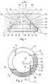
- a swirl nozzle for atomizing a liquid shows an outer body 10, from the outside 12 of which a nozzle outlet opening 14 designed as a cylindrical bore extends into an interior of the outer body 10 extends into it.
- This nozzle outlet opening 14 is adjoined by an essentially conical recess 16, the wall surfaces 18 of which form the lateral surfaces of a truncated cone which is arranged coaxially with the nozzle outlet opening 14 and is rotationally symmetrical with respect to a central axis 20.
- An inner body 22 is inserted into this recess 16, which has a circular-cylindrical region 24, which is adjoined by a frustoconical region 26, the base surface 28 of which is identical to the circular surface.
- This frustoconical region 26 is formed in such a way that lateral surfaces 30 are the same section of the conical jacket on which the wall surfaces 18 of the recess 16 also lie.
- the inner body 22 is held in a form-fitting manner in the recess 16 by a conical seat, the region of the wall surfaces 18 of the recess 16, in which the lateral surfaces 30 of the frustoconical region 26 of the inner body 22 abut, are referred to as conical seat surfaces 32 of the recess 16.
- a surface of the frustoconical region 26 of the inner body 22 opposite the base surface 28 and oriented parallel thereto extends perpendicularly to the central axis 20 and forms a swirl chamber floor 34.
- a region of the recess 16 lying above this swirl chamber floor 34 is referred to as the swirl chamber 36, the swirl chamber 36 delimiting wall surfaces 18 of the recess 16 are referred to as swirl chamber walls 38.
- a space enclosed by the recess 16 and arranged on a side of the inner body 22 opposite the swirl chamber 36 is referred to as the pressure space 40, in which the liquid intended for atomization is kept under pressure.
- a plurality of swirl channels 42 lead from this pressure chamber 40 into the swirl chamber 36, whereby these swirl channels 42, as can be seen in particular from FIG.
- a center line 44 of each swirl duct 42, at least in the region of an opening 46 thereof, in the swirl chamber base 34 has a distance e from the central axis 20 and thus from the mouth opening 46, a liquid jet 48 emerges which, when leaving the orifice 46, lies in a plane 50 parallel to the central axis 20 and at a distance e from it and has a speed component 52 parallel to the swirl chamber base 34 and a speed component 54 parallel to the central axis 20.
- the distance e is generally referred to as eccentricity e of the swirl nozzle.
- a fluid vortex 56 is formed about the central axis 20, in the center of which a cylinder-like air core 58 remains coaxial to the central axis 20, around which the fluid vortex 56 flows, so that a liquid film cone 60 finally emerges from the nozzle outlet opening 14 its own instability breaks down into small liquid droplets.
- a swirl parameter S o of such a nozzle is defined as follows where ⁇ is the slope of the swirl channels 42 relative to the swirl chamber base 34, the exit radius ⁇ a is the radius of the nozzle outlet opening 14 and f1, f2, f3, f4 are the cross-sectional areas of the swirl channels 42.
- ⁇ is the slope of the swirl channels 42 relative to the swirl chamber base 34
- ⁇ a is the radius of the nozzle outlet opening 14
- f1, f2, f3, f4 are the cross-sectional areas of the swirl channels 42.
- a definition of the swirl parameter can also be found in the research report DFVLR-FB 87-25 (ISSN 0171-1342), page 22.
- an air core always occurs with a swirl nozzle if the swirl parameter So> 1.
- the occurrence of an air core can also be made dependent on the ratio of the sum of all swirl channel areas f 1, f 2, f 3, f4 to the cross-sectional area of the nozzle outlet opening, which should be less than 5 for this purpose.
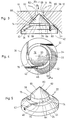
- FIGS. 3 to 5 Based on this known design of a known swirl nozzle, a first exemplary embodiment of a swirl nozzle according to the invention, shown in FIGS. 3 to 5, shows the same parts and features, which are therefore also provided with the same reference numerals in FIGS. 3 to 5.
- a displacement body 62 is placed on the swirl chamber base 34, which has a cylindrical base 64 to which a cone-shaped tip 66 is connected, with a base 68 of the cone-shaped tip 66 the end face 70 of the cylindrical base 64 facing this is identical.
- the entire displacement body 62 is designed to be rotationally symmetrical with respect to the central axis 20, the cylindrical base 64 extending in the radial direction with respect to the central axis 20 up to the mouth openings 46 of the swirl channels 42, so that the displacement body 62 covers the swirl chamber base 34 in its central region 72 and a cylindrical outer surface 74 of the cylindrical base 64 delimits a free annular region 76 of the swirl chamber base 34 towards the inside.
- cylindrical outer surface 74 of the cylindrical base and a section of the swirl chamber wall 38 arranged on the opposite side of the swirl chamber bottom as well as the circular region of the swirl chamber base 34 form an annular space 80, into which the liquid jet 48 is injected tangentially to the outer surface 74 of the cylindrical base 64.
- a surface 82 of the conical tip 66 designed as a conical surface preferably runs at a distance b from and parallel to an outlet-side section 84 of the swirl chamber wall 38, the width b preferably corresponding approximately to a width b of the swirl channels 42 .
- the swirl chamber 36 comprises an annular space 80 arranged on the swirl chamber bottom which is followed by a conical jacket-shaped space 86 delimited by the conical surface 82 of the displacement body 62 and the outlet-side section 84 of the swirl chamber wall, which in turn merges into the cylindrical bore of the nozzle outlet opening 14.
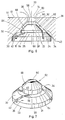
- FIGS. 6 and 7 A second embodiment of a swirl nozzle according to the invention, shown in FIGS. 6 and 7, is provided with the same reference numerals insofar as it is identical to the first embodiment of FIGS. 3 to 5, so that the description of the corresponding parts refers to the above statements is referred.
- the displacement body 62 no longer shows a conical tip, but rather a truncated cone 88 seated on the cylindrical base 64 with a front surface 90 opposite the base surface 68 and parallel to the swirl chamber base 34, which lies in the swirl chamber 36 and has a diameter, which is bigger than a diameter of the nozzle outlet opening 14.
- the displacement body 62 does not extend over the entire height of the swirl chamber from the swirl chamber floor 34 to a transition 92 of the swirl chamber walls 38 into the nozzle outlet opening 14, but ends with the front surface 90 at a distance therefrom.
- FIGS. 8 and 9 the same reference numerals are used insofar as the same parts are present as in the exemplary embodiments described above, so that reference can be made to the above description.
- the swirl channels 42 are no longer notches with a straight center line 44, but instead run Although along the lateral surfaces 30 of the inner body 22 as a straight line, but they show a mouth opening 46 designed as a circular ring segment 94, which thus offers the possibility of reducing the annular region 76 of the swirl body base 34 to the width b of the swirl channel 42, so that the distance e of the beam 48 emerging from the opening 46 from the central axis 20 is almost identical to an outer radius of the swirl chamber base 34.
- the displacement body 62 can thus only be designed as a conical tip 66, the base 68 of the conical tip 66 having a radial extension with respect to the central axis 20, which extends as far as an inner edge 96 of the orifices 46 of the swirl channels 42 designed as a circular ring segment.
- the swirl chamber is thus reduced to the cone-shaped space 86, which lies between the conical surface 82 of the displacement body 62 and the swirl chamber wall 38.
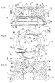
- FIGS. 10 and 11 A fourth exemplary embodiment of a swirl nozzle according to the invention, shown in FIGS. 10 and 11, shows the same parts as the exemplary embodiments described above insofar as the same reference numerals are used.
- the fourth exemplary embodiment differs in that the wall surfaces of the recess 16 have two different sections 98 and 100, the section 98 directly adjoining the nozzle outlet opening 14 corresponding to a truncated cone surface whose taper angle is greater than that of a truncated cone surface of the section 100 adjoining the section 98, the truncated cone surface of the section 98 along a line of contact 102 merges into the truncated cone surface of the partial area 100.
- the conical seat surface 32 against which the inner body 22 with its lateral surfaces 30 rests, is formed by the partial region 100.
- This inner body 22 is identical to the inner body 22 of the third exemplary embodiment with regard to the design of the swirl channels 42 and their mouth openings 46.
- the displacement body 62 seated on the swirl chamber base 34 is designed as a conical tip 66, just as in the third exemplary embodiment.
- the conical surface 82 now runs parallel to the partial area 98 at a distance b, which corresponds approximately to the width of the swirl channels 42.
- the partial area 100 advantageously extends over the conical seat surface 32 in the direction of the nozzle outlet opening 14 up to the contact line 102, so that the swirl chamber 36
- an annular space 104 formed by the partial region 100 which extends beyond the conical seat surface 32 as far as the line of contact 102, the annular region 76 and part of the surface 82 of the displacer 62 and the conical jacket-shaped space 86, delimited by the partial region 98 and the remaining part of the surface 82 of the displacer 62.
- a fifth embodiment of the swirl nozzle according to the invention is largely identical to the fourth embodiment, so that the same parts are also provided with the same reference numerals.
- the swirl channels 42 run from the pressure chamber 40 to the swirl chamber 36 in the region of the lateral surface 30 of the inner body 22 in a spiral with respect to the central axis 20, so that these swirl channels 42 have a smaller gradient than the central axis 20 the swirl channels 42 in the fourth embodiment.
- the jet 48 emerging from the orifice 46 has a smaller component 54 perpendicular to the swirl chamber floor 34 and a larger tangential flow component parallel to the swirl chamber floor 34, and thus a larger overall speed component, with the same overall flow velocity as in the swirl duct 42 of the previous exemplary embodiment the central axis 20 in the swirl channel 36 can be reached.
- a return bore 104 is additionally provided, which is arranged concentrically to the central axis 20 and opens into the swirl chamber 36 opposite the nozzle outlet opening 14 in the region of the displacement body 62.
- the displacement body 62 is no longer a cone, but merely a truncated cone, the front surface of which is now formed by an opening 106 in the return bore 104.
- This return bore 104 thus extends through the entire displacement body 62 and also through the inner body 22 and is connected to a conventional return flow path, which is described, for example, in German patent application P 37 03 075.2.
- a sixth exemplary embodiment, shown in FIGS. 14 to 16, represents a variant of the first exemplary embodiment, shown in FIGS. 3 to 5.
- the same parts are also provided with the same reference numerals, so that with regard to their description can be referred to the explanations of the first embodiment.
- this sixth exemplary embodiment shows return bores 110 machined into the conical surface 82 of the conical tip 66, which with longitudinal axes 112 perpendicular to the conical surface 82 penetrate into the displacement body 62 towards its central axis 20, whereby they coaxially into one Central axis arranged return channel 114 open out, which is of the conical Tip 66 of the displacer leads in the opposite direction into an interior of the nozzle.
- the return bores 110 are not arranged in the region of the nozzle outlet opening 14, but in a region overlapped by the outlet-side section 84 of the swirl chamber wall 38, so that the return bore 110 does not lie in the region of an air core which arises in the nozzle outlet opening 14.
- the so-called return mass flow ratio can be advantageously controlled without having to change a diameter of the return bore, as in the known arrangements of a return bore, which makes sense for the possible dimensions and viscosity ratios are always associated with difficulties.
- a fifth embodiment of the swirl nozzle according to the invention, shown in FIGS. 17 and 18, has similarities to the second embodiment, so that the same parts are also provided with the same reference numerals.
- the swirl channels 42 run from the pressure chamber 40 to the swirl chamber 36 in the region of the lateral surface 30 of the inner body 22 in a spiral with respect to the central axis 20, so that these swirl channels 42 have a smaller gradient than the central axis 20 Swirl channels 42 in the second embodiment.
- the jet emerging from the orifice 46 has a smaller component 54 perpendicular to the swirl chamber floor 34 and a larger speed component parallel to the swirl chamber floor 34 and thus a larger tangential component with respect to the central axis at the same overall flow velocity as in the swirl duct 42 of the previous embodiment 20 is reachable in the swirl channel 36.
- the orifices 46 are expanded to form a ring segment cutout 120, the width of which corresponds to the width of the annular swirl chamber base 34 between the frustoconical displacement body 62 and the swirl chamber walls 38.
- the displacement body 62 rises directly from the swirl chamber base 34 without the cylindrical shoulder as a truncated cone 88 and extends to the front surface 90, which has a diameter approximately corresponding to the diameter of the nozzle outlet bore 14.
- Particularly advantageous in the seventh embodiment is the fact that it is easy to manufacture and that the cross-sectional area of the orifices 46 is large, which leads to relatively low pressure losses due to viscosity.
Landscapes
- Nozzles (AREA)
Abstract
Description
Die Erfindung betrifft eine Dralldüse zum Zerstäuben einer Flüssigkeit mit einer sich über einem Drallkammerboden erhebenden und zu einer dem Drallkammerboden gegenüberliegenden Düsenaustrittsöffnung hin verjüngenden Drallkammer, mit mindestens einem gegenüber einer Mittelachse der Drallkammer seitlich versetzt in diese mündenden Drallkanal, mit einem Drallparameter von >1, mit einem sich von dem Drallkammerboden erhebenden und die Ausbildung eines Luftkerns in einem bodenseitigen Drallkammerbereich verhindernden Verdrängungskörper, welcher konzentrisch zur Mittelachse angeordnet ist und im bodenseitigen Teil einen Außendurchmesser aufweist, der mindestens einem Durchmesser der Düsenaustrittsöffnung entspricht.The invention relates to a swirl nozzle for atomizing a liquid with a swirl chamber rising above a swirl chamber floor and tapering towards a nozzle outlet opening opposite the swirl chamber floor, with at least one swirl channel offset laterally with respect to a central axis of the swirl chamber and having a swirl parameter of> 1 a displacement body which rises from the swirl chamber base and prevents the formation of an air core in a base-side swirl chamber region, which is arranged concentrically to the central axis and has an outer diameter in the base part which corresponds to at least one diameter of the nozzle outlet opening.
Bei derartigen bekannten Dralldüsen strömt die zu zerstäubende Flüssigkeit durch den Drallkanal vorzugsweise in tangentialer Richtung in die Drallkammer ein, in welcher sie sich in Richtung der Mittelachse der Drallkammer unter Vergrößerung ihrer Umfangsgeschwindigkeit bewegt. Da die Flüssigkeit bei einem Drallparameter der Dralldüse von >1 aufgrund der Zentrifugalkräfte nicht bis zur Mittelachse strömen kann, entsteht um die Mittelachse herum ein sich über die gesamte Höhe der Drallkammer erstreckender Luftkern, um den die Flüssigkeit herumströmt und somit als rotierender Flüssigkeitsfilmring die Düsenaustrittsöffnung passiert und anschließend einen Flüssigkeitsfilmkegel bildet, der aufgrund seiner eigenen Instabilität in kleine Flüssigkeitströpfchen zerfällt.In such known swirl nozzles, the liquid to be atomized flows through the swirl channel, preferably in a tangential direction into the swirl chamber, in which it moves in the direction of the central axis of the swirl chamber, increasing its peripheral speed. Since the liquid cannot flow to the central axis with a swirl parameter of the swirl nozzle of> 1 due to the centrifugal forces, an air core extends around the central axis, which extends over the entire height of the swirl chamber, around which the liquid flows and thus passes through the nozzle outlet opening as a rotating liquid film ring and then forms a liquid film cone, which due to its own instability disintegrates into small liquid droplets.
Eine Dralldüse der eingangs genannten Art ist in der FR-A-1 560 603 offenbart. Diese zeigt ebenfalls eine Dralldüse, bei welcher mit großer Wahrscheinlichkeit der Drallparameter >1 ist und welche ebenfalls einen kegelförmigen Verdrängungskörper aufweist.A swirl nozzle of the type mentioned in the opening paragraph is disclosed in FR-A-1 560 603. This also shows a swirl nozzle in which the swirl parameter is very likely to be> 1 and which also has a conical displacement body.
Die aus der US-A-2,065,161, der GB-A-162 172 und der DE-A-175 561 bekannten Dralldüsen sind für die vorliegende Erfindung insofern nicht einschlägig, da bei allen Konstruktionen gemäß diesen Druckschriften der Drallparameter <1 ist oder sich kein Luftkern ergibt.The swirl nozzles known from US-A-2,065,161, GB-A-162 172 and DE-A-175 561 are not relevant to the present invention in that the swirl parameter is <1 or not at all in accordance with these constructions Air core results.
Bei der US-A-2,065-161 beispielsweise wurde seitens des Erfinders ein Drallparameter von <0,7 ermittelt.In US-A-2,065-161, for example, the inventor determined a swirl parameter of <0.7.
Bei der GB-A-162 172 wurde ein Drallparameter <0,5 ermittelt und bei der DE-A-175 561 ist davon auszugehen, daß gar kein Luftkern vorliegt. Darüber hinaus ergibt sich aus dieser Druckschrift, daß der Kegelkörper dazu dient, den Öffnungswinkel des Sprühkegels zu verändern, was gegen die Verdrängung eines Luftkerns spricht. Im übrigen wurde ein Drallparameter von ungefähr 0,4 ermittelt.A swirl parameter <0.5 was determined in GB-A-162 172 and in DE-A-175 561 it can be assumed that there is no air core at all. In addition, it emerges from this document that the cone body serves to change the opening angle of the spray cone, which speaks against the displacement of an air core. In addition, a swirl parameter of approximately 0.4 was determined.
Um möglichst feine Flüssigkeitströpfchen zu erreichen, ist ein großer Luftkerndurchmesser erwünscht, welcher nur bei entsprechend großem Eingangsdrallimpuls des Flüssigkeitsstrahls erreichbar ist. Dieser könnte einerseits dadurch vergrößert werden, daß die Tangentialgeschwindigkeit des Flüssigkeitsstrahls vergrößert wird. Diese Tangentialgeschwindigkeit ist jedoch praktisch festgelegt durch einen sinnvollerweise maximalen Druck und einen aufgrund der Verstopfungsgefahr minimalen Querschnitt. Andererseits könnte der Eingangsdrallimpuls dadurch vergrößert werden, daß man die sogenannte Drallkanalexzentrizität, das heißt den Abstand einer Mittellinie des Drallkanals von der Mittelachse, erhöht. Diese Maßnahme vergrößert bei den bekannten Dralldüsen jedoch die von einem Luftkerndurchmesser und einer Luftkernlänge abhängigen Drallverluste, so daß in der Praxis auch hinsichtlich der Drallkanalexzentrizität bei den bekannten Dralldüsen keine Verbesserungen mehr möglich sind.In order to achieve the finest possible droplets of liquid, a large air core diameter is desired, which can only be achieved with a correspondingly large input swirl pulse of the liquid jet. On the one hand, this could be increased by increasing the tangential velocity of the liquid jet. However, this tangential speed is practically determined by a sensibly maximum pressure and a minimal cross section due to the risk of blockage. On the other hand, the input swirl pulse could be increased by increasing the so-called swirl channel eccentricity, that is, the distance of a center line of the swirl channel from the central axis. In the known swirl nozzles, however, this measure increases the swirl losses which depend on an air core diameter and an air core length, so that in practice no improvements are possible with regard to the swirl channel eccentricity in the known swirl nozzles.
Der Erfindung liegt daher die Aufgabe zugrunde, eine Dralldüse der gattungsgemäßen Art derart zu verbessern, daß diese eine Vergrößerung des Eingangsdrallimpulses bei gleichbleibenden oder geringeren Drallverlusten zuläßt.The invention is therefore based on the object of improving a swirl nozzle of the generic type in such a way that it permits an increase in the input swirl pulse with constant or lower swirl losses.
Diese Aufgabe wird bei einer Dralldüse der eingangs beschriebenen Art erfindungsgemäß dadurch gelöst, daß der Verdrängungskörper mit einer Rücklaufbohrung versehen ist.This object is achieved according to the invention in a swirl nozzle of the type described in the opening paragraph in that the displacement body is provided with a return bore.
Das erfindungsgemäße Vorsehen des Verdrängungskörpers hat den Vorteil, daß die Drallkammer im bodenseitigen Bereich die Form eines um den Verdrängungskörper umlaufenden Ringraums hat, so daß sich in diesem Bereich kein Luftkern ausbilden kann, welcher zu den bereits beschriebenen Drallverlusten führt. Somit kann bei der erfindungsgemäßenThe provision of the displacement body according to the invention has the advantage that the swirl chamber in the bottom area has the shape of an annular space surrounding the displacement body, so that no air core can form in this area, which leads to the swirl losses already described. Thus, with the invention
Dralldüse die Drallkanalexzentrizität größer gewählt werden, ohne daß sich insgesamt die Drallverluste erhöhen, so daß eine gute Zerstäubungsqualität der erfindungsgemäßen Dralldüsen erreichbar ist. Es ist sogar möglich, die Drallkanalexzentrizität so weit zu erhöhen, daß die Tangentialgeschwindigkeit des Flüssigkeitsstrahls geringer und somit ein Querschnitt der Drallkanäle größer gewählt werden kann, so daß sich die Verstopfungsgefahr der Düse verringert.Swirl nozzle, the swirl channel eccentricity can be chosen larger without increasing the swirl losses overall, so that a good atomization quality of the swirl nozzles according to the invention can be achieved. It is even possible to increase the swirl channel eccentricity to such an extent that the tangential velocity of the liquid jet can be reduced and thus a cross section of the swirl channels can be chosen larger, so that the risk of clogging of the nozzle is reduced.
Aus der US-A-2,030,041 ergibt sich lediglich Hintergrundinformation zur Möglichkeit des Vorsehens eines Rücklaufkanals, da die mit der vorliegenden Drallkammer im weitesten Sinn vergleichbare Wirbelkammer selbst keinen Rücklaufkanal aufweist, sondern über einen Durchlaß mit einer inneren Wirbelkammer verbunden ist, von welcher ihrerseits wiederum Rücklaufkanäle ausgehen.From US-A-2,030,041 there is only background information on the possibility of providing a return channel, since the swirl chamber which is comparable with the present swirl chamber in the broadest sense does not itself have a return channel, but is connected via a passage to an inner swirl chamber, from which in turn return channels going out.
Daraus folgt, daß die Düse gemäß der US-A-2,030,041 nach einem völlig anderem und mit der vorliegenden Erfindung gar nicht vergleichbaren Prinzip arbeitet und insbesondere auch ein Verdrängungskörper völlig fehlt, so daß dem Fachmann keinerlei Anhaltspunkt dafür gegeben ist, in dem Verdrängungskörper einen Rücklaufkanal vorzusehen.It follows that the nozzle according to US-A-2,030,041 operates according to a completely different principle that is not at all comparable with the present invention, and in particular that a displacement body is completely absent, so that the person skilled in the art has no indication of a return channel in the displacement body to provide.
Es liegt aber ebenfalls im Rahmen der vorliegenden Erfindung, wenn der Verdrängungskörper mit einer zentrischen Rücklaufbohrung versehen ist, deren weitere Merkmale beispielsweise in der DE-A-3 703 075 beschrieben ist.However, it is also within the scope of the present invention if the displacement body is provided with a central return bore, the further features of which is described, for example, in DE-A-3 703 075.
Als Alternative zur Anordnung der Rücklaufbohrung zentrisch zum Verdrängungskörper bietet die vorliegende erfindungsgemäße Lösung die Möglichkeit, die Rücklaufbohrung exzentrisch zum Verdrängungskörper anzuordnen. Hierbei ist es besonders vorteilhaft, wenn die Rücklaufbohrung in einem Abstand von der Mittelachse des Verdrängungskörpers angeordnet ist, welcher mindestens einem Radius der Düsenaustrittsöffnung entspricht, so daß ein möglicherweise im Bereich der Austrittsöffnung entstehender Restluftkern nicht über der Rücklaufbohrung steht und somit diese beeinflußt.As an alternative to arranging the return bore centrally to the displacement body, the solution according to the invention offers the possibility of arranging the return bore eccentrically to the displacement body. It is particularly advantageous here if the return bore is arranged at a distance from the central axis of the displacement body which corresponds to at least one radius of the nozzle outlet opening, so that a residual air core which possibly arises in the region of the outlet opening does not stand above the return bore and thus influences it.
Schließlich ist es zweckmäßig, wenn die Rücklaufbohrungen in einem Abstand von der Mittelachse angeordnet sind, welcher kleiner ist als der Abstand der Mündungsöffnung der Drallkanäle.Finally, it is expedient if the return bores are arranged at a distance from the central axis which is smaller than the distance from the mouth opening of the swirl channels.
Ferner ist eine Dralldüse vorteilhaft, welche einen Außenkörper aufweist, der die Düsenaustrittsöffnung und eine sich an diese anschließende, sich längs der Mittelachse erstreckende sowie mit zunehmender Erstreckung einen größeren Querschnitt aufweisende Ausnehmung umfaßt, und in diese Ausnehmung formschlüssig ein Innenkörper mit einem zur Mittelachse senkrecht stehenden Drallkammerboden einsetzbar ist, so daß der Drallkammerboden und zwischen diesem und der Düsenaustrittsöffnung liegende Wandflächen der Ausnehmung die Drallkammer begrenzen, und bei welcher die Wandflächen der Ausnehmung durch Mantelflächen von zur Mittelachse koaxialen Kegelstümpfen gebildet sind, wobei ein Teilbereich der Wandflächen der Ausnehmung eine Kegelsitzfläche für den kegelstumpfförmig ausgebildeten Innenkörper bilden und wobei die Kegelsitzfläche einen kleineren Kegelwinkel aufweist als ein weiterer sich an die Düsenaustrittsöffnung anschließender Teilbereich der Drallkammerwand.Furthermore, a swirl nozzle is advantageous which has an outer body which comprises the nozzle outlet opening and a recess which adjoins it and which extends along the central axis and has a larger cross section with increasing extension, and in this recess an inner body with a form which is perpendicular to the central axis Swirl chamber floor can be used so that the swirl chamber floor and wall surfaces of the recess lying between this and the nozzle outlet opening limit the swirl chamber, and in which the wall surfaces of the recess are formed by lateral surfaces of truncated cones that are coaxial with the central axis, a partial region of the wall surfaces of the recess being a conical seat surface for the Form a truncated cone-shaped inner body and the conical seat surface has a smaller cone angle than a further portion of the swirl chamber wall adjoining the nozzle outlet opening.
Dadurch läßt sich die erfindungsgemäße Dralldüse besonders einfach fertigen, da eine Kegelfläche mit konventionellen Verfahren einfach herstellbar ist.As a result, the swirl nozzle according to the invention can be manufactured particularly easily, since a conical surface can be easily produced using conventional methods.
Ferner läßt sich bei der erfindungsgemäßen Dralldüse dadurch die Höhe der Drallkammer und somit die Länge des Luftkerns möglichst gering halten, daß die Drallkammerwand eine Kegelmantelfläche mit einem möglichst großen Kegelwinkel bildet, welcher jedoch einen schlechten formschlüssigen Sitz des Innenteils zur Folge hätte, so daß die Wandflächen der Ausnehmung die die Kegelsitzfläche für das kegelstumpfförmig ausgebildete Innenteil bilden, einen kleineren Kegelwinkel aufweist als ein sich an die Düsenaustrittsöffnung anschließender Teilbereich der Drallkammerwand.Furthermore, in the swirl nozzle according to the invention, the height of the swirl chamber and thus the length of the air core can be kept as small as possible that the swirl chamber wall forms a conical surface with the largest possible cone angle, but which would result in a poor positive fit of the inner part, so that the wall surfaces of the recess which form the conical seat surface for the frustoconical inner part has a smaller cone angle than a portion of the swirl chamber wall adjoining the nozzle outlet opening.
Insbesondere im Zusammenhang mit der letztgenannten Ausführungsform der erfindungsgemäßen Dralldüse hat es sich als zweckmäßig erwiesen, wenn der Verdrängungskörper ein Kegel mit einem dem sich an die Düsenaustrittsöffnung anschließenden Teilbereich entsprechenden Kegelwinkel ist.In particular in connection with the last-mentioned embodiment of the swirl nozzle according to the invention, it has proven to be expedient if the displacement body is a cone with a cone angle corresponding to the partial area adjoining the nozzle outlet opening.
Im Rahmen der erfindungsgemäßen Lösung hat es sich als besonders vorteilhaft erwiesen, wenn der Verdrängungskörper sich mit einem mindestens dem Durchmesser der Düsenaustrittsöffnungen entsprechenden mittleren Durchmesser über mindestens ungefähr die halbe Höhe der Drallkammer in Richtung auf die Düsenaustrittsöffnung erstreckt.In the context of the solution according to the invention, it has proven to be particularly advantageous if the displacement body extends with a mean diameter corresponding at least to the diameter of the nozzle outlet openings over at least approximately half the height of the swirl chamber in the direction of the nozzle outlet opening.
Noch günstiger ist es jedoch, wenn der Verdrängungskörper sich mit einem mindestens dem Durchmesser der Düsenaustrittsöffnungen entsprechenden mittleren Durchmesser über mindestens ungefähr zwei Drittel der Höhe der Drallkammer erstreckt.However, it is even more favorable if the displacement body extends over at least approximately two thirds of the height of the swirl chamber with a mean diameter corresponding at least to the diameter of the nozzle outlet openings.
Um möglichst gleichmäßige Strömungsverhältnisse in der Drallkammer zu erreichen, hat es sich als äußerst zweckmäßig erwiesen, wenn eine einer äußeren Drallkammerwand zugewandte Oberfläche des Verdrängungskörpers in jeder Querschnittsebene bezüglich der Mittelachse ringsumlaufend jeweils einen konstanten Abstand von dieser aufweist.In order to achieve flow conditions in the swirl chamber which are as uniform as possible, it has proven to be extremely expedient if a surface of the displacement body facing an outer swirl chamber wall has a constant distance from it in each cross-sectional plane with respect to the central axis all around.
In Fortbildung der vorstehend genannten Lösung ist es zweckmäßig, wenn in einem der Düsenaustrittsöffnung zugewandten Teil des Verdrängungskörpers die der Drallkammerwand zugewandten Oberflächen in konstantem Abstand von dieser verlaufen, so daß die Drallkammer in diesem Bereich ein Ringkanal mit konstantem hydraulischen Durchmesser ist, der eine Gleichverteilung der umlaufenden Flüssigkeit bewirkt.In a development of the above-mentioned solution, it is expedient if, in a part of the displacement body facing the nozzle outlet opening, the surfaces facing the swirl chamber wall run at a constant distance therefrom, so that the swirl chamber in this area is an annular channel with a constant hydraulic diameter, which distributes the load evenly circulating liquid causes.
Bei der Bemessung des Abstands hat es sich als besonders vorteilhaft erwiesen, wenn der Abstand ungefähr einer Breite des Drallkanals entspricht.When dimensioning the distance, it has proven to be particularly advantageous if the distance corresponds approximately to a width of the swirl channel.
Im Hinblick auf die Form der Drallkammer hat es sich als zweckmäßig herausgestellt, wenn diese rotationssymmetrisch zur Mittelachse ausgebildet ist, so daß dies zur Folge hat, daß zwangsläufig auch der Verdrängungskörper rotationssymmetrisch ausgebildet sein muß.With regard to the shape of the swirl chamber, it has proven to be expedient if it is designed to be rotationally symmetrical to the central axis, so that this has the consequence that the displacement body must also be designed to be rotationally symmetrical.
Bei dem bislang beschriebenen Ausführungsbeispiel wurde nicht näher erläutert, wie die Drallkanäle in die Drallkammer münden. Deren Einmündung kann beliebig vorgesehen sein. Im Hinblick auf die Herstellung einer erfindungsgemäßen Dralldüse hat es sich jedoch als vorteilhaft erwiesen, wenn Mündungsöffnungen der Drallkanäle in einem um den Verdrängungskörper herum verlaufenden ringförmigen Bereich des Drallkammerbodens liegen.In the exemplary embodiment described so far, it was not explained in more detail how the swirl channels open into the swirl chamber. The junction can be provided as desired. With regard to the production of a swirl nozzle according to the invention, however, it has proven to be advantageous if the orifices of the swirl channels are located in an annular region of the swirl chamber base which extends around the displacement body.
Da, wie bereits eingangs erläutert, eine möglichst große Exzentrizität der einmündenden Drallkanäle erwünscht ist, ist bei einem bevorzugten Ausführungsbeispiel vorgesehen, daß eine Breite des ringförmigen Bereichs einer Erstreckung der Mündungsöffnung von einem Außenrand dieses Bereichs in radialer Richtung nach innen entspricht, das heißt, daß dieser ringförmige Bereich lediglich so breit gewählt ist, daß dieser die Mündungsöffnung des Drallkanals aufnehmen kann.Since, as already explained at the outset, as large an eccentricity as possible of the swirl channels opening out is desired, in a preferred exemplary embodiment it is provided that a width of the annular region corresponds to an extension of the mouth opening from an outer edge of this region in the radial direction inwards, that is to say that this ring-shaped area is only so wide that it can accommodate the opening of the swirl channel.
Wie bereits eingangs beschrieben, ist zweckmäßigerweise vorgesehen, daß der Drallkanal im Mündungsbereich mit seiner Mittellinie im wesentlichen tangential zur Drallkammerwand verläuft. Eine besonders große Drallkanalexzentrizität läßt sich jedoch dann erreichen, wenn der Drallkanal mit einer als Kreissegment ausgebildeten Mündungsöffnung entlang eines Außenrandbereichs des Drallkammerbodens in die Drallkammer mündet, da in diesem Fall die radiale Erstreckung der Mündungsöffnung in Richtung auf die Mittelachse lediglich einer Breite des Drallkanals entspricht und der Flüssigkeitsstrahl beim Eintreten in die Drallkammer somit entlang der Drallkammerwand strömt und dabei bei vorgegebenem Drallkammerdurchmesser in größtmöglichem Abstand von der Mittelachse in die Drallkammer einströmt.As already described at the beginning, it is expediently provided that the swirl channel in the mouth region runs essentially tangentially to the swirl chamber wall. A particularly large swirl channel eccentricity can, however, be achieved if the swirl channel with a mouth opening designed as a segment of a circle opens into the swirl chamber along an outer edge region of the swirl chamber base, since in this case the radial extent of the mouth opening in the direction of the central axis only corresponds to a width of the swirl channel and the liquid jet thus flows along the swirl chamber wall when entering the swirl chamber and flows into the swirl chamber at the greatest possible distance from the central axis for a given swirl chamber diameter.
Besonders im Hinblick auf eine möglichst einfache Herstellung der erfindungsgemäßen Dralldüse ist es zweckmäßig, wenn der Drallkanal geradegerichtet von einem Druckraum zur Drallkammer verläuft. Noch vorteilhafter ist es jedoch, wenn der Drallkanal spiralförmig bezüglich der Mittelachse von einem Druckraum zur Drallkammer verläuft, da in diesem Fall der Drallkanal bezüglich der Mittelachse mit einer geringeren Steigung versehen werden kann und somit ausgehend von einer konstanten Strömungsgeschwindigkeit der Flüssigkeit in diesem Drallkanal der aus dieser austretende Flüssigkeitsstrahl eine möglichst große Tangentialgeschwindigkeitskomponente in einer Ebene senkrecht zur Mittelachse und eine möglichst kleine Geschwindigkeitskomponente parallel zur Mittelachse aufweist.Particularly with a view to making the swirl nozzle according to the invention as simple as possible, it is expedient if the swirl duct runs in a straight line from a pressure chamber to the swirl chamber. It is even more advantageous, however, if the swirl duct runs spirally with respect to the central axis from a pressure chamber to the swirl chamber, since in this case the swirl duct can be provided with a smaller slope with respect to the central axis Thus, starting from a constant flow velocity of the liquid in this swirl channel, the liquid jet emerging from it has the largest possible tangential velocity component in a plane perpendicular to the central axis and the smallest possible velocity component parallel to the central axis.
In allen Fällen werden die Drallkanäle vorzugsweise einen im wesentlichen konstanten Querschnitt aufweisen.In all cases, the swirl channels will preferably have a substantially constant cross section.
Weitere Merkmale und Vorteile sind Gegenstand der nachfolgenden Beschreibung sowie der zeichnerischen Darstellung einiger Ausführungsbeispiele. In der Zeichnung zeigen:
- Fig. 1
- einen Schnitt durch eine bekannte Dralldüse;
- Fig. 2
- eine Ansicht in Richtung des Pfeiles A in Fig. 1;
- Fig. 3
- einen Schnitt durch ein erstes Ausführungsbeispiel der erfindungsgemäßen Dralldüse;
- Fig. 4
- eine Ansicht in Richtung des Pfeiles B in Fig. 3;
- Fig. 5
- eine perspektivische Darstellung eines erfindungsgemäßen Innenteils;
- Fig. 6
- einen Schnitt ähnlich Fig. 3 durch ein zweites Ausführungsbeispiel;
- Fig. 7
- eine perspektivische Ansicht ähnlich Fig. 5 des zweiten Ausführungsbeispiels;
- Fig. 8
- einen Schnitt ähnlich Fig. 3 durch ein drittes Ausführungsbeispiel;
- Fig. 9
- eine Ansicht in Richtung des Pfeiles C in Fig.8;
- Fig. 10
- einen Schnitt ähnlich Fig. 3 durch ein viertes Ausführungsbeispiel;
- Fig. 11
- eine Ansicht in Richtung des Pfeiles D in Fig.10;
- Fig. 12
- einen Schnitt ähnlich Fig. 3 durch ein fünftes Ausführungsbeispiel und
- Fig. 13
- eine Ansicht in Richtung des Pfeiles E in Fig. 12.
- Fig. 14
- eine Ansicht ähnlich Fig. 3 eines sechsten Ausführungsbeispiels;
- Fig. 15
- eine Draufsicht ähnlich Fig. 4 auf das sechste Ausführungsbeispiel;
- Fig. 16
- einen Schnitt längs Linie 16-16 in Fig. 15;
- Fig. 17
- eine Ansicht ähnlich Fig. 3 eines siebten Ausführungsbeispiels;
- Fig. 18
- eine Draufsicht ähnlich Fig. 4 auf das siebte Ausführungsbeispiel.
- Fig. 1
- a section through a known swirl nozzle;
- Fig. 2
- a view in the direction of arrow A in Fig. 1;
- Fig. 3
- a section through a first embodiment of the swirl nozzle according to the invention;
- Fig. 4
- a view in the direction of arrow B in Fig. 3;
- Fig. 5
- a perspective view of an inner part according to the invention;
- Fig. 6
- a section similar to Figure 3 through a second embodiment.
- Fig. 7
- a perspective view similar to Figure 5 of the second embodiment.
- Fig. 8
- a section similar to Figure 3 through a third embodiment.
- Fig. 9
- a view in the direction of arrow C in Figure 8;
- Fig. 10
- a section similar to Figure 3 through a fourth embodiment.
- Fig. 11
- a view in the direction of arrow D in Fig.10;
- Fig. 12
- a section similar to FIG. 3 through a fifth embodiment and
- Fig. 13
- a view in the direction of arrow E in Fig. 12.
- Fig. 14
- a view similar to Figure 3 of a sixth embodiment.
- Fig. 15
- a plan view similar to Figure 4 of the sixth embodiment.
- Fig. 16
- a section along line 16-16 in Fig. 15;
- Fig. 17
- a view similar to Figure 3 of a seventh embodiment.
- Fig. 18
- a plan view similar to FIG. 4 of the seventh embodiment.
Eine Dralldüse zum Zerstäuben einer Flüssigkeit, wie sie aus dem Stand der Technik bekannt ist, dargestellt in den Fig. 1 und 2, zeigt einen Außenkörper 10, von dessen Außenseite 12 ausgehend sich eine als zylindrische Bohrung ausgebildete Düsenaustrittsöffnung 14 in ein Inneres des Außenkörpers 10 hinein erstreckt. An diese Düsenaustrittsöffnung 14 schließt sich eine im wesentlichen kegelförmig ausgebildete Ausnehmung 16 an, deren Wandflächen 18 die Mantelflächen eines koaxial zur Düsenaustrittsöffnung 14 angeordneten und zu einer Mittelachse 20 rotationssymmetrischen Kegelstumpfes bilden. In diese Ausnehmung 16 ist ein Innenkörper 22 eingesetzt, welcher einen kreiszylindrischen Bereich 24 aufweist, an welchen sich ein kegelstumpfförmiger Bereich 26 anschließt, dessen Grundfläche 28 mit der Kreisfläche identisch ist. Dieser kegelstumpfförmige Bereich 26 ist so ausgebildet, daß Mantelflächen 30 desselben Abschnitts des Kegelmantels sind, auf welchem auch die Wandflächen 18 der Ausnehmung 16 liegen. Somit ist der Innenkörper 22 durch einen Kegelsitz formschlüssig in der Ausnehmung 16 gehalten, wobei der Bereich der Wandflächen 18 der Ausnehmung 16, in welchem die Mantelflächen 30 des kegelstumpfförmigen Bereichs 26 des Innenkörpers 22 anliegen, als Kegelsitzflächen 32 der Ausnehmung 16 bezeichnet sind.A swirl nozzle for atomizing a liquid, as is known from the prior art, shown in FIGS. 1 and 2, shows an
Eine der Grundfläche 28 gegenüberliegende und parallel zu dieser ausgerichtete Fläche des kegelstumpfförmigen Bereichs 26 des Innenkörpers 22 erstreckt sich senkrecht zur Mittelachse 20 und bildet einen Drallkammerboden 34. Ein über diesem Drallkammerboden 34 liegender Bereich der Ausnehmung 16 wird als Drallkammer 36 bezeichnet, wobei die die Drallkammer 36 begrenzenden Wandflächen 18 der Ausnehmung 16 als Drallkammerwände 38 bezeichnet sind. Ein von der Ausnehmung 16 umschlossenen und auf einer der Drallkammer 36 gegenüberliegenden Seite des Innenkörpers 22 angeordneter Raum wird als Druckraum 40 bezeichnet, in welchem die zum Zerstäuben vorgesehene Flüssigkeit unter Druck gehalten ist. Von diesem Druckraum 40 führen mehrere Drallkanäle 42 in die Drallkammer 36, wobei diese Drallkanäle 42, wie insbesondere aus Fig. 2 zu ersehen ist, vorzugsweise als Einkerbungen in den Mantelflächen 30 ausgebildet sind, die in den Druckraum 40 mit einem rechteckigen und ungefähr quadratischen Querschnitt im kreiszylindrischen Bereich 24 des Innenkörpers 22 münden und in der Drallkammer 36 im Bereich des Drallkammerbodens 34 und vorzugsweise in einem bezüglich der Mittelachse 20 radial außen liegenden Bereich münden, wobei eine Mittellinie 44 jedes Drallkanals 42, zumindest im Bereich einer Mündungsöffnung 46 desselben, im Drallkammerboden 34 einen Abstand e von der Mittelachse 20 aufweist und somit aus der Mündungsöffnung 46 ein Flüssigkeitsstrahl 48 austritt, welcher bei Verlassen der Mündungsöffnung 46 in einer zur Mittelachse 20 parallelen und im Abstand e von dieser verlaufenden Ebene 50 liegt und dabei eine Geschwindigkeitskomponente 52 parallel zum Drallkammerboden 34 aufweist sowie eine Geschwindigkeitskomponente 54 parallel zur Mittelachse 20. Der Abstand e wird allgemein als Exzentrizität e der Dralldüse bezeichnet. Somit entsteht in der Drallkammer 36 ein Flüssigkeitswirbel 56 um die Mittelachse 20, in dessen Mitte ein zylinderähnlicher koaxial zur Mittelachse 20 stehender Luftkern 58 stehen bleibt, um welchen der Flüssigkeitswirbel 56 herumströmt, so daß aus der Düsenaustrittsöffnung 14 schließlich ein Flüssigkeitsfilmkegel 60 austritt, der von seiner eigenen Instabilität in kleine Flüssigkeitströpfchen zerfällt.A surface of the
Ein Drallparameter So einer derartigen Düse ist folgendermaßen definiert
wobei γ die Steigung der Drallkanäle 42 gegenüber dem Drallkammerboden 34 bedeutet, der Austrittsradius τa der Radius der der Düsenaustrittsöffnung 14 ist und f₁, f₂, f₃, f₄ die Querschnittsflächen der Drallkanäle 42 sind. Eine Definition des Drallparameters ist außerdem aus dem Forschungsbericht DFVLR-FB 87-25 (ISSN 0171-1342), Seite 22 zu entnehmen.A swirl parameter S o of such a nozzle is defined as follows
where γ is the slope of the
Bei einer Dralldüse tritt immer dann ein Luftkern auf, wenn der Drallparameter So >1 ist. Alternativ dazu kann das Auftreten eines Luftkerns auch von dem Verhältnis der Summe aller Drallkanalflächen f₁, f₂, f₃, f₄ zur Querschnittsfläche der Düsenaustrittsöffnung abhängig gemacht werden, welches hierzu kleiner als 5 sein sollte.An air core always occurs with a swirl nozzle if the swirl parameter So> 1. Alternatively, the occurrence of an air core can also be made dependent on the ratio of the sum of all swirl channel areas f 1, f 2,
Ausgehend von diesem bekannten Aufbau einer bekannten Dralldüse zeigt ein erstes Ausführungsbeispiel einer erfindungsgemäßen Dralldüse, dargestellt in den Fig. 3 bis 5, dieselben Teile und Merkmale, die somit in den Fig. 3 bis 5 auch mit denselben Bezugszeichen versehen sind.Based on this known design of a known swirl nozzle, a first exemplary embodiment of a swirl nozzle according to the invention, shown in FIGS. 3 to 5, shows the same parts and features, which are therefore also provided with the same reference numerals in FIGS. 3 to 5.
Bezüglich der Beschreibung wird auf die vorstehenden Ausführungen verwiesen.With regard to the description, reference is made to the above statements.
Im Gegensatz zu der bekannten Dralldüse ist bei dem ersten Ausführungsbeispiel der erfindungsgemäßen Dralldüse auf den Drallkammerboden 34 ein Verdrängungskörper 62 aufgesetzt, welcher einen zylindrischen Sockel 64 aufweist, an welchen sich eine kegelförmig ausgebildete Spitze 66 anschließt, wobei eine Grundfläche 68 der kegelförmig ausgebildeten Spitze 66 mit der dieser zugewandten Stirnseite 70 des zylindrischen Sockels 64 identisch ist.In contrast to the known swirl nozzle, in the first exemplary embodiment of the swirl nozzle according to the invention, a
Der gesamte Verdrängungskörper 62 ist rotationssymmetrisch zur Mittelachse 20 ausgebildet, wobei sich der zylindrische Sockel 64 in radialer Richtung bezüglich der Mittelachse 20 bis zu den Mündungsöffnungen 46 der Drallkanäle 42 nach außen erstreckt, so daß der Verdrängungskörper 62 den Drallkammerboden 34 in seinem zentralen Bereich 72 überdeckt und eine zylindrische Außenfläche 74 des zylindrischen Sockels 64 einen freibleibenden kreisringförmigen Bereich 76 des Drallkammerbodens 34 nach innen hin begrenzt.The
Somit bilden die zylindrische Außenfläche 74 des zylindrischen Sockels und ein dieser gegenüberliegender drallkammerbodenseitig angeordneter Abschnitt der Drallkammerwand 38 sowie der kreisringförmige Bereich des Drallkammerbodens 34 einen Ringraum 80, in welchen der Flüssigkeitsstrahl 48 tangential zur Außenfläche 74 des zylindrischen Sockels 64 eingespritzt wird.Thus, the cylindrical
Eine als Kegelmantelfläche ausgebildete Oberfläche 82 der kegelförmigen Spitze 66 verläuft, wie in Fig. 3 dargestellt, vorzugsweise in einem Abstand b von einem austrittsseitigen Abschnitt 84 der Drallkammerwand 38 und parallel zu diesem, wobei vorzugsweise die Breite b ungefähr einer Breite b der Drallkanäle 42 entspricht.As shown in FIG. 3, a
Somit umfaßt die Drallkammer 36 bei dem ersten Ausführungsbeispiel der erfindungsgemäßen Dralldüse einen drallkammerbodenseitig angeordneten Ringraum 80, an welchen sich ein von der kegelförmigen Oberfläche 82 des Verdrängungskörpers 62 und dem austrittsseitigen Abschnitt 84 der Drallkammerwand begrenzter kegelmantelförmiger Raum 86 anschließt, welcher seinerseits in die zylindrische Bohrung der Düsenaustrittsöffnung 14 übergeht.Thus, in the first exemplary embodiment of the swirl nozzle according to the invention, the
Somit wurde durch den Verdrängungskörper 62 erreicht, daß in der Drallkammer 36 selbst kann Luftkern 58 mehr vorhanden ist, welcher sich auf die Flüssigkeitsströmung in der Drallkammer 36 negativ auswirken könnte. Lediglich noch im Bereich der Düsenaustrittsöffnung 14 bildet sich ein Restbereich eines Luftkerns, um welchen herum der Flüssigkeitsfilmkegel aus der Düsenaustrittsöffnung 14 austritt.It was thus achieved by the
Ein zweites Ausführungsbeispiel einer erfindungsgemäßen Dralldüse, dargestellt in den Fig. 6 und 7, ist insoweit als es mit dem ersten Ausführungsbeispiel der Fig. 3 bis 5 identisch ist, mit denselben Bezugszeichen versehen, so daß bezüglich der Beschreibung der entsprechenden Teile auf die vorstehenden Ausführungen verwiesen wird.A second embodiment of a swirl nozzle according to the invention, shown in FIGS. 6 and 7, is provided with the same reference numerals insofar as it is identical to the first embodiment of FIGS. 3 to 5, so that the description of the corresponding parts refers to the above statements is referred.
Im Gegensatz zum ersten Ausführungsbeispiel zeigt der Verdrängungskörper 62 keine kegelförmige Spitze mehr, sondern einen auf dem zylindrischen Sockel 64 sitzenden Kegelstumpf 88 mit einer dessen Grundfläche 68 gegenüberliegenden und zu dem Drallkammerboden 34 parallelen Frontfläche 90, welche in der Drallkammer 36 liegt und einen Durchmesser aufweist, der größer ist als ein Durchmesser der Düsenaustrittsöffnung 14. Somit erstreckt sich bei diesem Ausführungsbeispiel der Verdrängungskörper 62 nicht über die gesamte Höhe der Drallkammer von dem Drallkammerboden 34 bis zu einem Übergang 92 der Drallkammerwände 38 in die Düsenaustrittsöffnung 14, sondern endet mit der Frontfläche 90 im Abstand von diesem. Damit liegen oberhalb dieser Frontfläche 90 in der Drallkammer 36 dieselben Strömungsverhältnisse vor wie beim Stand der Technik oberhalb des Drallkammerbodens 34, so daß sich über der Frontfläche 90 ein Luftkern 58 bildet, welcher sich noch zu einem geringen Teil, nämlich über eine dem Abstand der Frontfläche 90 von dem Übergang 92 zwischen der Drallkammerwand 38 und der Düsenaustrittsöffnung 14 entsprechenden Strecke, in der Drallkammer 36 erstreckt. Trotzdem werden mit diesem zweiten Ausführungsbeispiel die erfindungsgemäßen Vorteile erreicht, da der Bereich des Luftkerns 58, längs welchem die unerwünschten Eigenschaften desselben wirksam werden, wesentlich kürzer ist als bei Nichtvorhandensein des erfindungsgemäßen Verdrängungskörpers 62.In contrast to the first exemplary embodiment, the
Bei einem dritten Ausführungsbeispiel der erfindungsgemäßen Dralldüse, dargestellt in den Fig. 8 und 9, sind insoweit als dieselben Teile wie bei den vorstehend beschriebenen Ausführungsbeispielen vorhanden sind, dieselben Bezugszeichen verwendet, so daß auf die vorstehende Beschreibung verwiesen werden kann.In a third exemplary embodiment of the swirl nozzle according to the invention, shown in FIGS. 8 and 9, the same reference numerals are used insofar as the same parts are present as in the exemplary embodiments described above, so that reference can be made to the above description.
Im Gegensatz zu den vorstehend beschriebenen Ausführungsbeispielen sind die Drallkanäle 42 keine Einkerbungen mit einer geraden Mittellinie 44 mehr, sondern verlaufen zwar längs der Mantelflächen 30 des Innenkörpers 22 als Gerade, zeigen aber eine als Kreisringsegment 94 ausgebildete Mündungsöffnung 46, welche somit die Möglichkeit bietet, den kreisringförmigen Bereich 76 des Drallkörperbodens 34 auf die Breite b des Drallkanals 42 zu reduzieren, so daß der Abstand e des aus der Mündungsöffnung 46 austretenden Strahls 48 von der Mittelachse 20 nahezu mit einem Außenradius des Drallkammerbodens 34 identisch ist.In contrast to the exemplary embodiments described above, the
Damit kann der Verdrängungskörper 62 lediglich als kegelförmige Spitze 66 ausgebildet sein, wobei die Grundfläche 68 der kegelförmigen Spitze 66 bezüglich der Mittelachse 20 eine radiale Erstreckung hat, die bis zu einer Innenkante 96 der als Kreisringsegment ausgebildeten Mündungsöffnungen 46 der Drallkanäle 42 reicht. Somit ist bei diesem dritten Ausführungsbeispiel die Drallkammer auf den kegelmantelförmigen Raum 86 reduziert, welcher zwischen der kegelförmigen Oberfläche 82 des Verdrängungskörpers 62 und der Drallkammerwand 38 liegt.The
Ein viertes Ausführungsbeispiel einer erfindungsgemäßen Dralldüse, dargestellt in den Fig. 10 und 11, zeigt insoweit als dieselben Bezugszeichen verwendet sind, dieselben Teile wie die vorstehend beschriebenen Ausführungsbeispiele.A fourth exemplary embodiment of a swirl nozzle according to the invention, shown in FIGS. 10 and 11, shows the same parts as the exemplary embodiments described above insofar as the same reference numerals are used.
Im Gegensatz zu den bisher beschriebenen Ausführungsbeispielen unterscheidet sich das vierte Ausführungsbeispiel dadurch, daß die Wandflächen der Ausnehmung 16 zwei unterschiedliche Teilbereiche 98 und 100 aufweisen, wobei der sich unmittelbar an die Düsenaustrittsöffnung 14 anschließende Teilbereich 98 einer Kegelstumpfmantelfläche entspricht, deren Kegelwinkel größer ist als derjenige einer Kegelstumpfmantelfläche des sich an den Teilbereich 98 anschließenden Teilbereichs 100, wobei die Kegelstumpfmantelfläche des Teilbereichs 98 längs einer Berührungslinie 102 in die Kegelstumpfmantelfläche des Teilbereichs 100 übergeht.In contrast to the previously described exemplary embodiments, the fourth exemplary embodiment differs in that the wall surfaces of the
Von dem Teilbereich 100 wird dabei die Kegelsitzfläche 32 gebildet, an welcher der Innenkörper 22 mit seinen Mantelflächen 30 anliegt. Dieser Innenkörper 22 ist hinsichtlich der Ausbildung der Drallkanäle 42 und deren Mündungsöffnungen 46 mit dem Innenkörper 22 des dritten Ausführungsbeispiels identisch. Außerdem ist auch der auf dem Drallkammerboden 34 aufsitzende Verdrängungskörper 62 genau wie beim dritten Ausführungsbeispiel als kegelförmige Spitze 66 ausgebildet. Allerdings verläuft die kegelförmige Oberfläche 82 nunmehr parallel zu dem Teilbereich 98 in einem Abstand b, welcher ungefähr der Breite der Drallkanäle 42 entspricht.The
Damit der kreisringförmige Bereich 76 des Drallkammerbodens 34 in der Breite des Drallkanals 42 gehalten werden kann und außerdem die kegelförmige Oberfläche 82 des Verdrängungskörpers 62 in einem der Breite der Drallkanäle 42 entsprechenden Abstand b von dem Teilbereich 98 verlaufen kann, erstreckt sich vorteilhaferweise der Teilbereich 100 über die Kegelsitzfläche 32 hinaus in Richtung auf die Düsenaustrittsöffnung 14 bis zur Berührungslinie 102, so daß die Drallkammer 36 bei dem vierten Ausführungsbeispiel einen Ringraum 104, gebildet durch den sich über die Kegelsitzfläche 32 hinaus bis zur Berührungslinie 102 erstreckenden Teilbereich 100, den kreisringförmigen Bereich 76 und einen Teil der Oberfläche 82 des Verdrängungskörpers 62 sowie den kegelmantelförmig ausgebildeten Raum 86, begrenzt durch den Teilbereich 98 und den übrigen Teil der Oberfläche 82 des Verdrängungskörpers 62, umfaßt.In order that the
Ein fünftes Ausführungsbeispiel der erfindungsgemäßen Dralldüse, dargestellt in den Fig. 12 und 13, ist weitgehend mit dem vierten Ausführungsbeispiel identisch, so daß dieselben Teile auch mit denselben Bezugszeichen versehen sind. Im Unterschied zu dem vierten Ausführungsbeispiel verlaufen allerdings die Drallkanäle 42 von dem Druckraum 40 zu der Drallkammer 36 im Bereich der Mantelfläche 30 des Innenkörpers 22 spiralförmig bezüglich der Mittelachse 20, so daß diese Drallkanäle 42, bezogen auf die Mittelachse 20, eine geringere Steigung aufweisen als die Drallkanäle 42 beim vierten Ausführungsbeispiel. Dies hat zur Folge, daß der aus der Mündungsöffnung 46 austretende Strahl 48 bei insgesamt gleicher Strömungsgeschwindigkeit wie in dem Drallkanal 42 des vorhergehenden Ausführungsbeispiels eine kleinere Komponente 54 senkrecht zum Drallkammerboden 34 und eine größere Tangentialströmungskomponente parallel zum Drallkammerboden 34 aufweist und damit insgesamt eine größere Geschwindigkeitskomponente bezüglich der Mittelachse 20 im Drallkanal 36 erreichbar ist.A fifth embodiment of the swirl nozzle according to the invention, shown in FIGS. 12 and 13, is largely identical to the fourth embodiment, so that the same parts are also provided with the same reference numerals. In contrast to the fourth exemplary embodiment, however, the
Bei einer besonders vorteilhaften Variante des fünften Ausführungsbeispiels ist noch zusätzlich eine Rücklaufbohrung 104 vorgesehen, welche konzentrisch zur Mittelachse 20 angeordnet ist und in die Drallkammer 36 der Düsenaustrittsöffnung 14 gegenüberliegend im Bereich des Verdrängungskörpers 62 mündet. Der Verdrängungskörper 62 ist hierbei kein Kegel mehr, sondern lediglich ein Kegelstumpf, dessen Frontfläche nunmehr durch eine Mündungsöffnung 106 der Rücklaufbohrung 104 gebildet ist. Diese Rücklaufbohrung 104 erstreckt sich somit durch den gesamten Verdrängungskörper 62 und auch durch den Innenkörper 22 hindurch und ist mit einem üblichen Rückströmweg verbunden, welcher beispielsweise in der deutschen Patentanmeldung P 37 03 075.2 beschrieben ist.In a particularly advantageous variant of the fifth exemplary embodiment, a
Ein sechstes Ausführungsbeispiel, dargestellt in den Fig. 14 bis 16 stellt eine Variante des ersten Ausführungsbeispiels, dargestellt in den Fig. 3 bis 5, dar. Insoweit als gleiche Teile verwendet sind, sind diese auch mit denselben Bezugszeichen versehen, so daß hinsichtlich deren Beschreibung auf die Ausführungen zum ersten Ausführungsbeispiel verwiesen werden kann.A sixth exemplary embodiment, shown in FIGS. 14 to 16, represents a variant of the first exemplary embodiment, shown in FIGS. 3 to 5. Insofar as the same parts are used, they are also provided with the same reference numerals, so that with regard to their description can be referred to the explanations of the first embodiment.
Dieses sechste Ausführungsbeispiel zeigt im Gegensatz zum ersten Ausführungsbeispiel in die kegelförmige Oberfläche 82 der kegelförmigen Spitze 66 eingearbeitete Rücklaufbohrungen 110, welche mit senkrecht zu der kegelförmigen Oberfläche 82 stehenden Längsachsen 112 in den Verdrängungskörper 62 zu dessen Mittelachse 20 hin eindringen, wobei sie in einen koaxial zur Mittelachse angeordneten Rücklaufkanal 114 münden, welcher von der kegelförmigen Spitze 66 des Verdrängungskörpers in entgegengesetzter Richtung in ein Inneres der Düse führt.In contrast to the first exemplary embodiment, this sixth exemplary embodiment shows return bores 110 machined into the
Erfindungsgemäß sind die Rücklaufbohrungen 110 nicht im Bereich der Düsenaustrittsöffnung 14 angeordnet, sondern in einem von dem austrittsseitigen Abschnitt 84 der Drallkammerwand 38 übergriffenen, so daß die Rücklaufbohrung 110 nicht im Bereich eines in der Düsenaustrittsöffnung 14 entstehenden Luftkerns liegen.According to the invention, the return bores 110 are not arranged in the region of the
Durch Wahl einer bestimmten Exzentrizität der Rücklaufbohrungen 110, das heißt deren Abstand von der Mittelachse 20, läßt sich damit in vorteilhafter Weise das sogenannte Rücklaufmassenstromverhältnis regeln, ohne daß wie bei den bekannten Anordnungen einer Rücklaufbohrung ein Durchmesser der Rücklaufbohrung verändert werden müßte, was bei den sinnvoll möglichen Abmessungen und Viskositätsverhältnissen stets mit Schwierigkeiten verbunden ist.By choosing a certain eccentricity of the return bores 110, that is to say their distance from the
Ein fünftes Ausführungsbeispiel der erfindungsgemäßen Dralldüse, dargestellt in den Fig. 17 und 18, hat Ähnlichkeiten mit dem zweiten Ausführungsbeispiel, so daß dieselben Teile auch mit denselben Bezugszeichen versehen sind.A fifth embodiment of the swirl nozzle according to the invention, shown in FIGS. 17 and 18, has similarities to the second embodiment, so that the same parts are also provided with the same reference numerals.
Im Unterschied zum zweiten Ausführungsbeispiel verlaufen allerdings die Drallkanäle 42 von dem Druckraum 40 zu der Drallkammer 36 im Bereich der Mantelfläche 30 des Innenkörpers 22 spiralförmig bezüglich der Mittelachse 20, so daß diese Drallkanäle 42, bezogen auf die Mittelachse 20, eine geringere Steigung aufweisen als die Drallkanäle 42 beim zweiten Ausführungsbeispiel. Dies hat zur Folge, daß der aus der Mündungsöffnung 46 austretende Strahl bei insgesamt gleicher Strömungsgeschwindigkeit wie in dem Drallkanal 42 des vorhergehenden Ausführungsbeispiels eine kleinere Komponente 54 senkrecht zum Drallkammerboden 34 und eine größere Geschwindigkeitskomponente parallel zum Drallkammerboden 34 aufweist und damit insgesamt eine größere Tangentialkomponente bezüglich der Mittelachse 20 im Drallkanal 36 erreichbar ist.In contrast to the second exemplary embodiment, however, the
Ferner sind die Mündungsöffnungen 46 zu einem Ringsegmentausschnitt 120 erweitert, dessen Breite der Breite des ringförmigen Drallkammerbodens 34 zwischen dem kegelstumpfförmigen Verdrängungskörper 62 und den Drallkammerwänden 38 entspricht.Furthermore, the
Im Gegensatz zum zweiten Ausführungsbeispiel erhebt sich der Verdrängungskörper 62 ohne den zylindrischen Ansatz als Kegelstumpf 88 unmittelbar von dem Drallkammerboden 34 und erstreckt sich bis zu der Frontfläche 90, welche einen ungefähr dem Durchmesser der Düsenaustrittsbohrung 14 entsprechenden Durchmesser aufweist.In contrast to the second exemplary embodiment, the
Besonders vorteilhaft beim siebten Ausführungsbeispiel ist die Tatsache, daß dieses einfach zu fertigen ist und daß die Querschnittsfläche der Mündungsöffnungen 46 groß ist, was zu relativ geringen viskositätsbedingten Druckverlusten führt.Particularly advantageous in the seventh embodiment is the fact that it is easy to manufacture and that the cross-sectional area of the
Claims (14)
- Whirl nozzle for atomizing a liquid comprising a whirl chamber (36) rising above a whirl chamber base (34) and tapering towards a nozzle outlet opening (14) located opposite the whirl chamber base (34), at least one whirl channel laterally offset in relation to a central axis of the whirl chamber (36) and opening into said chamber, a whirl parameter of >1, a displacement member (62) rising above the whirl chamber base (34) and preventing the formation of an air core (58) in a region of the whirl chamber near the base, said displacement member being arranged concentrically to the central axis (20) and having in the section near the base an external diameter corresponding at least to a diameter of the nozzle outlet opening (14), characterized in that the displacement member (62) is provided with a reflux bore (104, 110).
- Whirl nozzle as defined in claim 1, characterized in that the displacement member (62) is provided with a central reflux bore (104).
- Whirl nozzle as defined in claim 1, characterized in that the displacement member (62) is provided with at least one eccentrically arranged reflux bore (110).
- Whirl nozzle as defined in claim 3, characterized in that the reflux bore (110) is arranged at a distance from the central axis (20) corresponding at least to a radius of the nozzle outlet opening (14).
- Whirl nozzle as defined in claim 4, characterized in that the reflux bore (110) is arranged at a distance from the central axis (20) smaller than the distance to the port (46) of the whirl channel (42).
- Whirl nozzle as defined in any of the preceding claims, characterized in that the whirl nozzle has an outer member (10) comprising the nozzle outlet opening (14) and a recess (16) adjoining said opening and extending along the central axis (20) as well as having a larger cross section the further it extends, that an inner member (22) having a whirl chamber base (34) extending perpendicularly to the central axis (20) is insertable into this recess (16) in a positively connected manner such that the whirl chamber base (34) and wall surfaces (18) of the recess (16) located between said base and the nozzle outlet opening (14) define the whirl chamber (36), that the wall surfaces (18) of the recess (16) are formed by surfaces of conical frustums coaxial to the central axis (20), that a section (100) of the wall surfaces (18) of the recess (16) forms a conical seating surface (32) for the inner member (22) frustoconical in design and that the conical seating surface (32) has a smaller cone angle than an additional section (98) of the whirl chamber wall (38) adjoining the nozzle outlet opening (14).
- Whirl nozzle as defined in any of the preceding claims, characterized in that the displacement member (62) extends over at least half the height of the whirl chamber (36) in the direction towards the nozzle outlet opening (14) with an average diameter corresponding at least to the diameter of the nozzle outlet opening (14).
- Whirl nozzle as defined in claim 7, characterized in that the displacement member (62) extends over at least two thirds of the height of the whirl chamber (36) in the direction towards the nozzle outlet opening (14) with an average diameter corresponding at least to the diameter of the nozzle outlet opening (14).
- Whirl nozzle as defined in any of the preceding claims, characterized in that a surface (74, 82) of the displacement member (62) facing a whirl chamber wall (38) is spaced at a constant distance from the whirl chamber wall (38) in each respective cross-sectional plane relative to the central axis (20) all the way round its circumference.
- Whirl nozzle as defined in claim 9, characterized in that in a section of the displacement member (62) facing the nozzle outlet opening (14) the surface (82) facing the whirl chamber wall (38) extends at a constant distance therefrom.
- Whirl nozzle as defined in claim 10, characterized in that the distance corresponds approximately to a width (b) of the whirl channel (42).
- Whirl nozzle as defined in any of the preceding claims, characterized in that a port (46) of the whirl channel (42) is located in an annular region (76) of the whirl chamber base (34) extending around the displacement member (62).
- Whirl nozzle as defined in claim 12, characterized in that the width of the annular region (76) is selected such that it corresponds to the extent of the port (46) from an outer edge of this region (76) in radial direction inwards.
- Whirl nozzle as defined in claim 13, characterized in that the whirl channel (42) opens into the whirl chamber (36) along an outer edge region of the whirl chamber base (34) with a port designed as a circular segment (94).
Priority Applications (1)
| Application Number | Priority Date | Filing Date | Title |
|---|---|---|---|
| EP93118034A EP0604741B1 (en) | 1987-12-11 | 1988-12-09 | Swirl nozzle for spraying a liquid |
Applications Claiming Priority (3)
| Application Number | Priority Date | Filing Date | Title |
|---|---|---|---|
| DE3742015 | 1987-12-11 | ||
| DE3742015 | 1987-12-11 | ||
| PCT/EP1988/001133 WO1989005195A1 (en) | 1987-12-11 | 1988-12-09 | Whirl nozzle for atomizing a liquid |
Related Child Applications (2)
| Application Number | Title | Priority Date | Filing Date |
|---|---|---|---|
| EP93118034A Division EP0604741B1 (en) | 1987-12-11 | 1988-12-09 | Swirl nozzle for spraying a liquid |
| EP93118034.3 Division-Into | 1993-11-06 |
Publications (2)
| Publication Number | Publication Date |
|---|---|
| EP0346417A1 EP0346417A1 (en) | 1989-12-20 |
| EP0346417B1 true EP0346417B1 (en) | 1994-10-05 |
Family
ID=6342366
Family Applications (2)
| Application Number | Title | Priority Date | Filing Date |
|---|---|---|---|
| EP93118034A Expired - Lifetime EP0604741B1 (en) | 1987-12-11 | 1988-12-09 | Swirl nozzle for spraying a liquid |
| EP89900234A Expired - Lifetime EP0346417B1 (en) | 1987-12-11 | 1988-12-09 | Whirl nozzle for atomizing a liquid |
Family Applications Before (1)
| Application Number | Title | Priority Date | Filing Date |
|---|---|---|---|
| EP93118034A Expired - Lifetime EP0604741B1 (en) | 1987-12-11 | 1988-12-09 | Swirl nozzle for spraying a liquid |
Country Status (4)
| Country | Link |
|---|---|
| US (1) | US5067655A (en) |
| EP (2) | EP0604741B1 (en) |
| DE (2) | DE3851750D1 (en) |
| WO (1) | WO1989005195A1 (en) |
Families Citing this family (90)
| Publication number | Priority date | Publication date | Assignee | Title |
|---|---|---|---|---|
| KR100210033B1 (en) * | 1991-05-20 | 1999-07-15 | 괴란 순트홀름 | Fire fighting equipment |
| US5655608A (en) * | 1991-05-20 | 1997-08-12 | Sundholm; Goeran | Fire fighting equipment |
| US5392993A (en) * | 1994-01-21 | 1995-02-28 | Grinnell Corporation, | Fire protection nozzle |
| US5522549A (en) * | 1994-10-24 | 1996-06-04 | Sheu; Kun N. | Jet nozzle assembly for removing pests from crops |
| US5697553A (en) * | 1995-03-03 | 1997-12-16 | Parker-Hannifin Corporation | Streaked spray nozzle for enhanced air/fuel mixing |
| SE504838C2 (en) * | 1995-08-31 | 1997-05-12 | Astra Ab | Device at a spray nozzle |
| US5765752A (en) * | 1996-01-26 | 1998-06-16 | Dgh Systems, L.L.C. | Airless atomizing nozzle and system for humidity control |
| US5921470A (en) * | 1997-03-20 | 1999-07-13 | Kamath; Bola R. | Air-atomizing oil burner utilizing a low pressure fan and nozzle |
| US6029746A (en) * | 1997-07-22 | 2000-02-29 | Vortech, Inc. | Self-excited jet stimulation tool for cleaning and stimulating wells |
| US6470980B1 (en) | 1997-07-22 | 2002-10-29 | Rex A. Dodd | Self-excited drill bit sub |
| US5954047A (en) * | 1997-10-17 | 1999-09-21 | Systemic Pulmonary Development, Ltd. | Methods and apparatus for delivering aerosolized medication |
| US6745763B2 (en) * | 1998-10-27 | 2004-06-08 | Garth T. Webb | Vaporizing device for administering sterile medication |
| RU2162919C2 (en) * | 1999-05-07 | 2001-02-10 | Курский государственный технический университет | Method of cooling the circulating water in cooling pond |
| US6418925B1 (en) * | 1999-05-20 | 2002-07-16 | Iep Pharmaceutical Devices Inc. | Low spray force, low retention atomization system |
| US6367471B1 (en) * | 1999-11-01 | 2002-04-09 | Sheffield Pharmaceuticals, Inc. | Internal vortex mechanism for inhaler device |
| JP2001137349A (en) * | 1999-11-16 | 2001-05-22 | Asahi Optical Co Ltd | Endoscope sprayer |
| JP3798928B2 (en) * | 1999-11-16 | 2006-07-19 | ペンタックス株式会社 | Connection structure of tube and base of endoscope treatment tool |
| FR2802446B1 (en) * | 1999-12-16 | 2002-04-12 | Oreal | NOZZLE FOR AEROSOL CONTAINER |
| DE10010881B4 (en) * | 2000-02-29 | 2006-09-07 | Torsten Dipl.-Ing. Clauß | Method and device for discharging liquid media |
| US6962152B1 (en) * | 2000-05-02 | 2005-11-08 | Salter Labs | Respiratory equipment spacer assembly |
| DE10024888B4 (en) * | 2000-05-16 | 2008-10-16 | Gea Wtt Gmbh | Plate heat exchanger with refrigerant distributor |
| IT1318646B1 (en) * | 2000-07-26 | 2003-08-27 | Medical Internat Licensing N V | NOZZLE PR ADMINISTRATIONS AND NASAL WASHES. |
| US8235919B2 (en) | 2001-01-12 | 2012-08-07 | Celleration, Inc. | Ultrasonic method and device for wound treatment |
| RU2204662C2 (en) * | 2001-06-13 | 2003-05-20 | Курский государственный технический университет | Method for cooling circulating water in cooling pond |
| DE10129367A1 (en) * | 2001-06-20 | 2003-01-09 | Klingenburg Gmbh | The air humidification |
| RU2205703C2 (en) * | 2001-06-21 | 2003-06-10 | Общество с ограниченной ответственностью "Эко-Сервис К" | Injector |
| JP4795637B2 (en) | 2001-09-28 | 2011-10-19 | カーブ テクノロジー,インコーポレイティド | Nose nebulizer |
| DE10154237A1 (en) * | 2001-11-07 | 2003-05-15 | Steag Microparts Gmbh | Manual sputterer, to spray liquid droplets on to a surface, has a spring acting on a piston with a manual release, to spray a portion of the stored liquid with a controlled droplet size |
| US20030102392A1 (en) * | 2001-12-03 | 2003-06-05 | Illinois Tool Works Inc. | Internal impingement nozzle |
| US6814307B2 (en) * | 2002-01-24 | 2004-11-09 | Combustion Components Associates, Inc. | Low NOx liquid fuel oil atomizer spray plate and fabrication method thereof |
| WO2003099359A1 (en) * | 2002-05-09 | 2003-12-04 | Kurve Technology, Inc. | Particle dispersion chamber for nasal nebulizer |
| US6659369B1 (en) * | 2002-06-12 | 2003-12-09 | Continental Afa Dispensing Company | High viscosity liquid sprayer nozzle assembly |
| US6808122B2 (en) * | 2002-08-19 | 2004-10-26 | Illinois Tool Works, Inc. | Spray gun with improved pre-atomization fluid mixing and breakup |
| DE50312628D1 (en) * | 2002-10-17 | 2010-05-27 | Braun Gmbh | MOUTH SHOWER AND SPRAY NOZZLE FOR GENERATING A LIQUID BEAM AND TOOTH CLEANING SYSTEM |
| GB0300939D0 (en) * | 2003-01-16 | 2003-02-12 | Unilever Plc | Method of creating a cosmetic spray |
| US7174717B2 (en) * | 2003-12-24 | 2007-02-13 | Pratt & Whitney Canada Corp. | Helical channel fuel distributor and method |
| DE102005037972A1 (en) * | 2005-08-11 | 2007-02-22 | Krauss-Maffei Kunststofftechnik Gmbh | Nozzle for spray head |
| RU2008139498A (en) * | 2006-03-07 | 2010-04-20 | БЕРИНГЕР ИНГЕЛЬХАЙМ ИНТЕРНАЦИОНАЛЬ ГмбХ (DE) | Vortex Spray Head |
| JP5400609B2 (en) * | 2006-05-17 | 2014-01-29 | メッドミックス システムズ アーゲー | Dispensing device having a spray assembly |
| US8491521B2 (en) * | 2007-01-04 | 2013-07-23 | Celleration, Inc. | Removable multi-channel applicator nozzle |
| KR101450122B1 (en) * | 2007-06-04 | 2014-10-21 | 렉티셀 오토모빌시스템 게엠베하 | Pressure Swirl Spray Nozzles for Spraying Curable Compositions, Related Manufacturing Methods and Methods of Use |
| US7712313B2 (en) * | 2007-08-22 | 2010-05-11 | Pratt & Whitney Canada Corp. | Fuel nozzle for a gas turbine engine |
| EP2077132A1 (en) | 2008-01-02 | 2009-07-08 | Boehringer Ingelheim Pharma GmbH & Co. KG | Dispensing device, storage device and method for dispensing a formulation |
| US8517009B2 (en) * | 2008-07-13 | 2013-08-27 | Map Pharmaceuticals, Inc. | Methods and apparatus for delivering aerosolized medication |
| RU2485245C2 (en) * | 2008-11-11 | 2013-06-20 | Геннадий Петрович Кузнецов | Method to create conditions to prevent ingress of sludge deposits from voronezh storage pond bottom into cooling pond of novovoronezh nuclear power plant |
| EP2414560B1 (en) | 2009-03-31 | 2013-10-23 | Boehringer Ingelheim International GmbH | Method for coating a surface of a component |
| US9265910B2 (en) | 2009-05-18 | 2016-02-23 | Boehringer Ingelheim International Gmbh | Adapter, inhalation device, and nebulizer |
| CA2671171C (en) | 2009-07-06 | 2017-12-12 | Northbasin Energy Services Inc. | Drill bit with a flow interrupter |
| EP2504051B1 (en) | 2009-11-25 | 2019-09-04 | Boehringer Ingelheim International GmbH | Nebulizer |
| US10016568B2 (en) | 2009-11-25 | 2018-07-10 | Boehringer Ingelheim International Gmbh | Nebulizer |
| CA2781792C (en) | 2009-11-25 | 2019-04-02 | Boehringer Ingelheim International Gmbh | Nebulizer |
| US8517124B2 (en) * | 2009-12-01 | 2013-08-27 | Northbasin Energy Services Inc. | PDC drill bit with flute design for better bit cleaning |
| US9174229B2 (en) * | 2010-06-11 | 2015-11-03 | The Procter & Gamble Company | Dispenser having non-frustro-conical funnel wall |
| US20110303767A1 (en) * | 2010-06-11 | 2011-12-15 | Scott Edward Smith | Dispenser having convergent flow path |
| EP2585151B1 (en) | 2010-06-24 | 2018-04-04 | Boehringer Ingelheim International GmbH | Nebulizer |
| US9332776B1 (en) * | 2010-09-27 | 2016-05-10 | ZoomEssence, Inc. | Methods and apparatus for low heat spray drying |
| KR20140003582A (en) * | 2011-01-31 | 2014-01-09 | 신 니뽄 바이오메디칼 라보라토리즈, 엘티디. | Intranasal delivery devices |
| EP2694220B1 (en) | 2011-04-01 | 2020-05-06 | Boehringer Ingelheim International GmbH | Medical device comprising a container |
| US9827384B2 (en) | 2011-05-23 | 2017-11-28 | Boehringer Ingelheim International Gmbh | Nebulizer |
| EP2570110B1 (en) * | 2011-09-15 | 2017-05-03 | Noxell Corporation | Aerosol hairspray product for styling and/or shaping hair |
| EP2570190A1 (en) * | 2011-09-15 | 2013-03-20 | Braun GmbH | Spray nozzle for dispensing a fluid and sprayer comprising such a spray nozzle |
| US20140339339A1 (en) * | 2011-11-03 | 2014-11-20 | Delavan Inc | Airblast injectors for multipoint injection and methods of assembly |
| US9188063B2 (en) | 2011-11-03 | 2015-11-17 | Delavan Inc. | Injectors for multipoint injection |
| WO2013152894A1 (en) | 2012-04-13 | 2013-10-17 | Boehringer Ingelheim International Gmbh | Atomiser with coding means |
| JP6643231B2 (en) | 2013-08-09 | 2020-02-12 | ベーリンガー インゲルハイム インターナショナル ゲゼルシャフト ミット ベシュレンクテル ハフツング | Nebulizer |
| ES2836977T3 (en) | 2013-08-09 | 2021-06-28 | Boehringer Ingelheim Int | Nebulizer |
| EP3074089B1 (en) | 2013-11-26 | 2025-03-05 | Alliqua Biomedical, Inc. | Systems for producing and delivering ultrasonic therapies for wound treatment and healing |
| CN103691587B (en) * | 2013-12-12 | 2017-03-29 | 中国神华能源股份有限公司 | Liquid distribution sprayer and desalinization spray equipment |
| US9689571B2 (en) * | 2014-01-15 | 2017-06-27 | Delavan Inc. | Offset stem fuel distributor |
| SG11201608891RA (en) | 2014-05-07 | 2016-11-29 | Boehringer Ingelheim Int | Nebulizer, indicator device and container |
| BR112016023983B1 (en) | 2014-05-07 | 2022-10-18 | Boehringer Ingelheim International Gmbh | CONTAINER FOR A NEBULIZER, NEBULIZER FOR A FLUID AND METHOD FOR CONNECTING A CONTAINER TO AN INDICATOR DEVICE |
| WO2015169430A1 (en) | 2014-05-07 | 2015-11-12 | Boehringer Ingelheim International Gmbh | Nebulizer |
| US10385809B2 (en) | 2015-03-31 | 2019-08-20 | Delavan Inc. | Fuel nozzles |
| US9897321B2 (en) | 2015-03-31 | 2018-02-20 | Delavan Inc. | Fuel nozzles |
| WO2017219138A1 (en) * | 2016-06-21 | 2017-12-28 | I3-Edge Ltd. | Method and system for stripping tubulars and the like comprising frustoconical air blade |
| DE202016103825U1 (en) * | 2016-07-14 | 2017-10-20 | SWEDEX GmbH Industrieprodukte | Swirl body and conical nozzle with such a swirl body |
| FR3055560B1 (en) * | 2016-09-02 | 2021-05-07 | Albea Le Treport | DISTRIBUTION HEAD OF A PRESSURIZED FLUID AND AEROSOL BOMB OR MANUAL ACTION PUMP INCLUDING SUCH A DISTRIBUTION HEAD |
| CN106621785A (en) * | 2017-02-23 | 2017-05-10 | 东方电气集团东方锅炉股份有限公司 | Device and method for removing sulfur trioxide in boiler flue gas |
| DE102017113207A1 (en) * | 2017-06-15 | 2018-12-20 | Alfons Kenter | Atomizer nozzle for atomizing a fluid |
| US9993787B1 (en) | 2017-08-04 | 2018-06-12 | ZoomEssence, Inc. | Ultrahigh efficiency spray drying apparatus and process |
| US10486173B2 (en) | 2017-08-04 | 2019-11-26 | ZoomEssence, Inc. | Ultrahigh efficiency spray drying apparatus and process |
| WO2019028446A1 (en) | 2017-08-04 | 2019-02-07 | ZoomEssence, Inc. | Ultrahigh efficiency spray drying apparatus and process |
| US10155234B1 (en) | 2017-08-04 | 2018-12-18 | ZoomEssence, Inc. | Ultrahigh efficiency spray drying apparatus and process |
| US9861945B1 (en) | 2017-08-04 | 2018-01-09 | ZoomEssence, Inc. | Ultrahigh efficiency spray drying apparatus and process |
| US10569244B2 (en) | 2018-04-28 | 2020-02-25 | ZoomEssence, Inc. | Low temperature spray drying of carrier-free compositions |
| DE102020204849A1 (en) | 2020-04-16 | 2021-10-21 | Siemens Aktiengesellschaft | Swirl nozzle with outer guide groove |
| FR3112292B1 (en) * | 2020-07-07 | 2025-11-21 | Aptar France Sas | Spray head and fluid product dispensing device comprising such a head |
| US12128118B2 (en) | 2021-07-29 | 2024-10-29 | The Procter & Gamble Company | Aerosol dispenser containing a hairspray composition and a nitrogen propellant |
| US20230090908A1 (en) * | 2021-09-23 | 2023-03-23 | GM Global Technology Operations LLC | Paint spray nozzle for a paint spray system |
| CN116116590B (en) * | 2023-04-18 | 2023-06-13 | 箭牌家居集团股份有限公司 | Water outlet device and shower head |
Family Cites Families (17)
| Publication number | Priority date | Publication date | Assignee | Title |
|---|---|---|---|---|
| DE314080C (en) * | ||||
| US1008119A (en) * | 1911-06-12 | 1911-11-07 | Union Iron Works Co | Liquid-atomizer. |
| DE280632C (en) * | 1912-08-19 | 1914-11-21 | ||
| US1650128A (en) * | 1920-04-05 | 1927-11-22 | Babcock & Wilcox Co | Method of and apparatus for spraying liquids |
| GB162172A (en) * | 1920-04-09 | 1921-04-28 | John Graves Mckean | Improvements in atomisers for liquid fuel and other liquids |
| US1757023A (en) * | 1926-10-20 | 1930-05-06 | Ira E Smith | Oil burner |
| DE556863C (en) * | 1928-04-23 | 1932-08-15 | Gustav Schlick | Atomizer nozzle |
| US2017467A (en) * | 1934-11-23 | 1935-10-15 | Leavitt R Loomis | Spray nozzle |
| US2065161A (en) * | 1935-01-28 | 1936-12-22 | Thompson Mfg Company | Full circle sprinkler |
| US2176356A (en) * | 1936-05-23 | 1939-10-17 | Jens A Paasche | Fluid spraying apparatus |
| US2374041A (en) * | 1942-01-31 | 1945-04-17 | Gen Furnaces Corp | Variable capacity atomizing device |
| US2984421A (en) * | 1958-08-11 | 1961-05-16 | Sarah A Hession | Adjustable aerosol device |
| FR1560603A (en) * | 1968-01-30 | 1969-03-21 | ||
| DE1750561B2 (en) * | 1968-05-14 | 1976-08-05 | Hoechst Ag, 6000 Frankfurt | DRUM-SHAPED SPIRAL NOZZLE FOR DIFFUSING POLLUTED LIQUIDS |
| US3684194A (en) * | 1970-10-29 | 1972-08-15 | Delavan Manufacturing Co | Spray nozzle |
| DE2814246A1 (en) * | 1978-04-03 | 1979-10-11 | Metallgesellschaft Ag | RETURN NOZZLE |
| DE3703075A1 (en) * | 1987-02-03 | 1988-08-11 | Deutsche Forsch Luft Raumfahrt | Swirl nozzle for atomising a liquid |
-
1988
- 1988-12-09 US US07/393,907 patent/US5067655A/en not_active Expired - Fee Related
- 1988-12-09 EP EP93118034A patent/EP0604741B1/en not_active Expired - Lifetime
- 1988-12-09 EP EP89900234A patent/EP0346417B1/en not_active Expired - Lifetime
- 1988-12-09 WO PCT/EP1988/001133 patent/WO1989005195A1/en not_active Ceased
- 1988-12-09 DE DE3851750T patent/DE3851750D1/en not_active Expired - Fee Related
- 1988-12-09 DE DE3856185T patent/DE3856185D1/en not_active Expired - Fee Related
Also Published As
| Publication number | Publication date |
|---|---|
| WO1989005195A1 (en) | 1989-06-15 |
| DE3851750D1 (en) | 1994-11-10 |
| EP0604741B1 (en) | 1998-05-13 |
| EP0346417A1 (en) | 1989-12-20 |
| US5067655A (en) | 1991-11-26 |
| EP0604741A2 (en) | 1994-07-06 |
| EP0604741A3 (en) | 1994-11-30 |
| DE3856185D1 (en) | 1998-06-18 |
Similar Documents
| Publication | Publication Date | Title |
|---|---|---|
| EP0346417B1 (en) | Whirl nozzle for atomizing a liquid | |
| DE1601958B2 (en) | ||
| EP0350721B1 (en) | Flow limiter | |
| DE102011078508A1 (en) | full cone nozzle | |
| DE2542240A1 (en) | HOLLOW CONE NOZZLE FOR SPRAYING LIQUID | |
| DE9314990U1 (en) | Jet regulator for connection to sanitary fittings | |
| DE68926396T2 (en) | PLASMA TORCH FOR TRANSFERED ARC | |
| EP1543882B1 (en) | Nozzle for a conical jet | |
| EP0801990B1 (en) | Spray nozzle, particularly for spraying water in fire protection installations | |
| EP3302815B1 (en) | Swirler and cone nozzle with such a swirler | |
| DE2141291C3 (en) | Spray nozzle to achieve a frustoconical spray mist | |
| DE69913442T2 (en) | Fluid atomizer | |
| DE3309742C2 (en) | ||
| DE2919074C2 (en) | ||
| DE3640818C1 (en) | Spray head for producing an air-liquid mixture, in particular for a cooling device | |
| DE3711695A1 (en) | Distribution cap for a device for the extracorporal treatment of blood or its components | |
| EP0646679B1 (en) | Strainer for water taps | |
| DE1942022A1 (en) | One-piece spray head for aerosol container | |
| EP0413173B1 (en) | Fuel injection nozzle for internal combustion engines | |
| DE4404881B4 (en) | writing implement | |
| DE3026014A1 (en) | NOZZLE FOR GENERATING A SPRAY JET | |
| DE19750068C1 (en) | Axial hollow cone nozzle for gas washer | |
| DE4040733A1 (en) | DEVICE FOR PRODUCING A STRAND OF MATERIAL WITH A CENTRAL OPENING | |
| DE3703075A1 (en) | Swirl nozzle for atomising a liquid | |
| DE2437644B2 (en) | Oxygen lance for converter |
Legal Events
| Date | Code | Title | Description |
|---|---|---|---|
| PUAI | Public reference made under article 153(3) epc to a published international application that has entered the european phase |
Free format text: ORIGINAL CODE: 0009012 |
|
| 17P | Request for examination filed |
Effective date: 19890727 |
|
| AK | Designated contracting states |
Kind code of ref document: A1 Designated state(s): AT BE CH DE FR GB IT LI LU NL SE |
|
| RBV | Designated contracting states (corrected) |
Designated state(s): CH DE LI |
|
| RAP1 | Party data changed (applicant data changed or rights of an application transferred) |
Owner name: DEUTSCHE FORSCHUNGSANSTALT FUER LUFT- UND RAUMFAHR |
|
| 17Q | First examination report despatched |
Effective date: 19920814 |
|
| GRAA | (expected) grant |
Free format text: ORIGINAL CODE: 0009210 |
|
| AK | Designated contracting states |
Kind code of ref document: B1 Designated state(s): CH DE LI |
|
| REF | Corresponds to: |
Ref document number: 3851750 Country of ref document: DE Date of ref document: 19941110 |
|
| PLBE | No opposition filed within time limit |
Free format text: ORIGINAL CODE: 0009261 |
|
| STAA | Information on the status of an ep patent application or granted ep patent |
Free format text: STATUS: NO OPPOSITION FILED WITHIN TIME LIMIT |
|
| 26N | No opposition filed | ||
| PGFP | Annual fee paid to national office [announced via postgrant information from national office to epo] |
Ref country code: DE Payment date: 19991117 Year of fee payment: 12 |
|
| PGFP | Annual fee paid to national office [announced via postgrant information from national office to epo] |
Ref country code: CH Payment date: 19991220 Year of fee payment: 12 |
|
| PG25 | Lapsed in a contracting state [announced via postgrant information from national office to epo] |
Ref country code: LI Free format text: LAPSE BECAUSE OF NON-PAYMENT OF DUE FEES Effective date: 20001231 Ref country code: CH Free format text: LAPSE BECAUSE OF NON-PAYMENT OF DUE FEES Effective date: 20001231 |
|
| REG | Reference to a national code |
Ref country code: CH Ref legal event code: PL |
|
| PG25 | Lapsed in a contracting state [announced via postgrant information from national office to epo] |
Ref country code: DE Free format text: LAPSE BECAUSE OF NON-PAYMENT OF DUE FEES Effective date: 20011002 |