JP5900494B2 - Medical instrument filter system - Google Patents
Medical instrument filter system Download PDFInfo
- Publication number
- JP5900494B2 JP5900494B2 JP2013519025A JP2013519025A JP5900494B2 JP 5900494 B2 JP5900494 B2 JP 5900494B2 JP 2013519025 A JP2013519025 A JP 2013519025A JP 2013519025 A JP2013519025 A JP 2013519025A JP 5900494 B2 JP5900494 B2 JP 5900494B2
- Authority
- JP
- Japan
- Prior art keywords
- filter
- liquid
- fine
- adsorption
- instrument according
- Prior art date
- Legal status (The legal status is an assumption and is not a legal conclusion. Google has not performed a legal analysis and makes no representation as to the accuracy of the status listed.)
- Active
Links
- 239000007788 liquid Substances 0.000 claims description 74
- 238000001179 sorption measurement Methods 0.000 claims description 59
- 239000002245 particle Substances 0.000 claims description 51
- 238000011045 prefiltration Methods 0.000 claims description 48
- 239000000463 material Substances 0.000 claims description 26
- 239000011148 porous material Substances 0.000 claims description 22
- 238000002360 preparation method Methods 0.000 claims description 17
- 239000012669 liquid formulation Substances 0.000 claims description 16
- 239000004033 plastic Substances 0.000 claims description 16
- 229920003023 plastic Polymers 0.000 claims description 16
- 238000000034 method Methods 0.000 claims description 15
- RTAQQCXQSZGOHL-UHFFFAOYSA-N Titanium Chemical compound [Ti] RTAQQCXQSZGOHL-UHFFFAOYSA-N 0.000 claims description 13
- 229910052719 titanium Inorganic materials 0.000 claims description 13
- 239000010936 titanium Substances 0.000 claims description 13
- 239000002105 nanoparticle Substances 0.000 claims description 11
- 239000000443 aerosol Substances 0.000 claims description 8
- 229940079593 drug Drugs 0.000 claims description 7
- 230000007717 exclusion Effects 0.000 claims description 7
- 239000000126 substance Substances 0.000 claims description 7
- -1 alcohol compound Chemical class 0.000 claims description 6
- 239000003814 drug Substances 0.000 claims description 6
- 230000000694 effects Effects 0.000 claims description 6
- 239000003365 glass fiber Substances 0.000 claims description 6
- TWNQGVIAIRXVLR-UHFFFAOYSA-N oxo(oxoalumanyloxy)alumane Chemical compound O=[Al]O[Al]=O TWNQGVIAIRXVLR-UHFFFAOYSA-N 0.000 claims description 6
- 230000009471 action Effects 0.000 claims description 5
- XUIMIQQOPSSXEZ-UHFFFAOYSA-N Silicon Chemical compound [Si] XUIMIQQOPSSXEZ-UHFFFAOYSA-N 0.000 claims description 4
- 239000011521 glass Substances 0.000 claims description 4
- 238000003780 insertion Methods 0.000 claims description 4
- 230000037431 insertion Effects 0.000 claims description 4
- 229910052710 silicon Inorganic materials 0.000 claims description 4
- 239000010703 silicon Substances 0.000 claims description 4
- 239000002131 composite material Substances 0.000 claims description 3
- 230000007423 decrease Effects 0.000 claims description 3
- 229920000049 Carbon (fiber) Polymers 0.000 claims description 2
- 229920003043 Cellulose fiber Polymers 0.000 claims description 2
- 239000004917 carbon fiber Substances 0.000 claims description 2
- 230000003993 interaction Effects 0.000 claims description 2
- 230000009878 intermolecular interaction Effects 0.000 claims description 2
- VNWKTOKETHGBQD-UHFFFAOYSA-N methane Chemical compound C VNWKTOKETHGBQD-UHFFFAOYSA-N 0.000 claims description 2
- 229920005594 polymer fiber Polymers 0.000 claims description 2
- 125000001453 quaternary ammonium group Chemical group 0.000 claims description 2
- 230000002829 reductive effect Effects 0.000 claims description 2
- 239000000306 component Substances 0.000 description 58
- 239000006199 nebulizer Substances 0.000 description 45
- 229910052751 metal Inorganic materials 0.000 description 23
- 239000002184 metal Substances 0.000 description 23
- 238000001914 filtration Methods 0.000 description 13
- 239000000203 mixture Substances 0.000 description 11
- LFQSCWFLJHTTHZ-UHFFFAOYSA-N Ethanol Chemical compound CCO LFQSCWFLJHTTHZ-UHFFFAOYSA-N 0.000 description 10
- 238000005516 engineering process Methods 0.000 description 8
- 238000009472 formulation Methods 0.000 description 8
- 230000008901 benefit Effects 0.000 description 7
- 239000012530 fluid Substances 0.000 description 7
- 238000002663 nebulization Methods 0.000 description 7
- 239000007789 gas Substances 0.000 description 6
- 230000008569 process Effects 0.000 description 6
- 239000007921 spray Substances 0.000 description 6
- 239000004698 Polyethylene Substances 0.000 description 5
- 230000015572 biosynthetic process Effects 0.000 description 5
- 229920000573 polyethylene Polymers 0.000 description 5
- 239000004743 Polypropylene Substances 0.000 description 4
- VYPSYNLAJGMNEJ-UHFFFAOYSA-N Silicium dioxide Chemical compound O=[Si]=O VYPSYNLAJGMNEJ-UHFFFAOYSA-N 0.000 description 4
- 230000002378 acidificating effect Effects 0.000 description 4
- 239000012042 active reagent Substances 0.000 description 4
- 229940126534 drug product Drugs 0.000 description 4
- 229910052739 hydrogen Inorganic materials 0.000 description 4
- 239000001257 hydrogen Substances 0.000 description 4
- 125000002887 hydroxy group Chemical group [H]O* 0.000 description 4
- 239000000825 pharmaceutical preparation Substances 0.000 description 4
- 239000000843 powder Substances 0.000 description 4
- 239000007787 solid Substances 0.000 description 4
- 239000000725 suspension Substances 0.000 description 4
- 239000013543 active substance Substances 0.000 description 3
- 230000002776 aggregation Effects 0.000 description 3
- 238000000151 deposition Methods 0.000 description 3
- 239000000835 fiber Substances 0.000 description 3
- 238000002347 injection Methods 0.000 description 3
- 239000007924 injection Substances 0.000 description 3
- 210000004072 lung Anatomy 0.000 description 3
- 238000004519 manufacturing process Methods 0.000 description 3
- 239000003595 mist Substances 0.000 description 3
- 229920001155 polypropylene Polymers 0.000 description 3
- 239000003380 propellant Substances 0.000 description 3
- 238000007789 sealing Methods 0.000 description 3
- 239000000243 solution Substances 0.000 description 3
- 239000002904 solvent Substances 0.000 description 3
- 230000002411 adverse Effects 0.000 description 2
- 238000005054 agglomeration Methods 0.000 description 2
- 239000010953 base metal Substances 0.000 description 2
- 230000008859 change Effects 0.000 description 2
- 239000000470 constituent Substances 0.000 description 2
- 230000007797 corrosion Effects 0.000 description 2
- 238000005260 corrosion Methods 0.000 description 2
- 230000008021 deposition Effects 0.000 description 2
- 238000013461 design Methods 0.000 description 2
- 239000006185 dispersion Substances 0.000 description 2
- 238000001746 injection moulding Methods 0.000 description 2
- 229940071648 metered dose inhaler Drugs 0.000 description 2
- BASFCYQUMIYNBI-UHFFFAOYSA-N platinum Chemical compound [Pt] BASFCYQUMIYNBI-UHFFFAOYSA-N 0.000 description 2
- 229920001343 polytetrafluoroethylene Polymers 0.000 description 2
- 239000004810 polytetrafluoroethylene Substances 0.000 description 2
- 238000000926 separation method Methods 0.000 description 2
- 239000000377 silicon dioxide Substances 0.000 description 2
- 239000007779 soft material Substances 0.000 description 2
- 230000001954 sterilising effect Effects 0.000 description 2
- 238000003860 storage Methods 0.000 description 2
- LERNTVKEWCAPOY-VOGVJGKGSA-N C[N+]1(C)[C@H]2C[C@H](C[C@@H]1[C@H]1O[C@@H]21)OC(=O)C(O)(c1cccs1)c1cccs1 Chemical compound C[N+]1(C)[C@H]2C[C@H](C[C@@H]1[C@H]1O[C@@H]21)OC(=O)C(O)(c1cccs1)c1cccs1 LERNTVKEWCAPOY-VOGVJGKGSA-N 0.000 description 1
- 229920000426 Microplastic Polymers 0.000 description 1
- BPQQTUXANYXVAA-UHFFFAOYSA-N Orthosilicate Chemical compound [O-][Si]([O-])([O-])[O-] BPQQTUXANYXVAA-UHFFFAOYSA-N 0.000 description 1
- 239000004696 Poly ether ether ketone Substances 0.000 description 1
- 238000005411 Van der Waals force Methods 0.000 description 1
- 239000003082 abrasive agent Substances 0.000 description 1
- 239000008186 active pharmaceutical agent Substances 0.000 description 1
- 239000003463 adsorbent Substances 0.000 description 1
- 238000004220 aggregation Methods 0.000 description 1
- 239000000556 agonist Substances 0.000 description 1
- 150000001298 alcohols Chemical class 0.000 description 1
- VXAUWWUXCIMFIM-UHFFFAOYSA-M aluminum;oxygen(2-);hydroxide Chemical compound [OH-].[O-2].[Al+3] VXAUWWUXCIMFIM-UHFFFAOYSA-M 0.000 description 1
- 238000004458 analytical method Methods 0.000 description 1
- 239000007864 aqueous solution Substances 0.000 description 1
- 238000000889 atomisation Methods 0.000 description 1
- JUPQTSLXMOCDHR-UHFFFAOYSA-N benzene-1,4-diol;bis(4-fluorophenyl)methanone Chemical compound OC1=CC=C(O)C=C1.C1=CC(F)=CC=C1C(=O)C1=CC=C(F)C=C1 JUPQTSLXMOCDHR-UHFFFAOYSA-N 0.000 description 1
- 238000009530 blood pressure measurement Methods 0.000 description 1
- 239000012876 carrier material Substances 0.000 description 1
- 239000000919 ceramic Substances 0.000 description 1
- 230000000052 comparative effect Effects 0.000 description 1
- 238000007906 compression Methods 0.000 description 1
- 230000006835 compression Effects 0.000 description 1
- 238000005520 cutting process Methods 0.000 description 1
- 230000003247 decreasing effect Effects 0.000 description 1
- 230000001419 dependent effect Effects 0.000 description 1
- 238000011161 development Methods 0.000 description 1
- 238000009826 distribution Methods 0.000 description 1
- 238000005553 drilling Methods 0.000 description 1
- 229920001971 elastomer Polymers 0.000 description 1
- 239000000806 elastomer Substances 0.000 description 1
- 238000009760 electrical discharge machining Methods 0.000 description 1
- 238000002474 experimental method Methods 0.000 description 1
- 239000000945 filler Substances 0.000 description 1
- 230000016615 flocculation Effects 0.000 description 1
- 238000005189 flocculation Methods 0.000 description 1
- 239000011888 foil Substances 0.000 description 1
- 238000007306 functionalization reaction Methods 0.000 description 1
- PCHJSUWPFVWCPO-UHFFFAOYSA-N gold Chemical compound [Au] PCHJSUWPFVWCPO-UHFFFAOYSA-N 0.000 description 1
- 239000010931 gold Substances 0.000 description 1
- 229910052737 gold Inorganic materials 0.000 description 1
- 238000009434 installation Methods 0.000 description 1
- 238000000691 measurement method Methods 0.000 description 1
- 230000007246 mechanism Effects 0.000 description 1
- 239000012528 membrane Substances 0.000 description 1
- QSHDDOUJBYECFT-UHFFFAOYSA-N mercury Chemical compound [Hg] QSHDDOUJBYECFT-UHFFFAOYSA-N 0.000 description 1
- 229910052753 mercury Inorganic materials 0.000 description 1
- 239000007769 metal material Substances 0.000 description 1
- 239000002923 metal particle Substances 0.000 description 1
- 239000007922 nasal spray Substances 0.000 description 1
- 229940097496 nasal spray Drugs 0.000 description 1
- 229910000510 noble metal Inorganic materials 0.000 description 1
- 239000012457 nonaqueous media Substances 0.000 description 1
- 239000003960 organic solvent Substances 0.000 description 1
- 239000005426 pharmaceutical component Substances 0.000 description 1
- 229910052697 platinum Inorganic materials 0.000 description 1
- 238000005498 polishing Methods 0.000 description 1
- 229920002530 polyetherether ketone Polymers 0.000 description 1
- 229920000098 polyolefin Polymers 0.000 description 1
- 239000010970 precious metal Substances 0.000 description 1
- 230000001681 protective effect Effects 0.000 description 1
- 230000005588 protonation Effects 0.000 description 1
- 238000000746 purification Methods 0.000 description 1
- 230000029058 respiratory gaseous exchange Effects 0.000 description 1
- 230000000717 retained effect Effects 0.000 description 1
- 239000004065 semiconductor Substances 0.000 description 1
- 230000035939 shock Effects 0.000 description 1
- 238000005245 sintering Methods 0.000 description 1
- 238000005507 spraying Methods 0.000 description 1
- 229910001220 stainless steel Inorganic materials 0.000 description 1
- 239000010935 stainless steel Substances 0.000 description 1
- 238000004659 sterilization and disinfection Methods 0.000 description 1
- 238000006557 surface reaction Methods 0.000 description 1
- 230000001225 therapeutic effect Effects 0.000 description 1
- 229960000257 tiotropium bromide Drugs 0.000 description 1
- 238000011144 upstream manufacturing Methods 0.000 description 1
Images


Classifications
-
- A—HUMAN NECESSITIES
- A61—MEDICAL OR VETERINARY SCIENCE; HYGIENE
- A61M—DEVICES FOR INTRODUCING MEDIA INTO, OR ONTO, THE BODY; DEVICES FOR TRANSDUCING BODY MEDIA OR FOR TAKING MEDIA FROM THE BODY; DEVICES FOR PRODUCING OR ENDING SLEEP OR STUPOR
- A61M11/00—Sprayers or atomisers specially adapted for therapeutic purposes
- A61M11/02—Sprayers or atomisers specially adapted for therapeutic purposes operated by air or other gas pressure applied to the liquid or other product to be sprayed or atomised
-
- A—HUMAN NECESSITIES
- A61—MEDICAL OR VETERINARY SCIENCE; HYGIENE
- A61M—DEVICES FOR INTRODUCING MEDIA INTO, OR ONTO, THE BODY; DEVICES FOR TRANSDUCING BODY MEDIA OR FOR TAKING MEDIA FROM THE BODY; DEVICES FOR PRODUCING OR ENDING SLEEP OR STUPOR
- A61M11/00—Sprayers or atomisers specially adapted for therapeutic purposes
- A61M11/001—Particle size control
- A61M11/003—Particle size control by passing the aerosol trough sieves or filters
-
- A—HUMAN NECESSITIES
- A61—MEDICAL OR VETERINARY SCIENCE; HYGIENE
- A61M—DEVICES FOR INTRODUCING MEDIA INTO, OR ONTO, THE BODY; DEVICES FOR TRANSDUCING BODY MEDIA OR FOR TAKING MEDIA FROM THE BODY; DEVICES FOR PRODUCING OR ENDING SLEEP OR STUPOR
- A61M11/00—Sprayers or atomisers specially adapted for therapeutic purposes
- A61M11/006—Sprayers or atomisers specially adapted for therapeutic purposes operated by applying mechanical pressure to the liquid to be sprayed or atomised
- A61M11/007—Syringe-type or piston-type sprayers or atomisers
-
- A—HUMAN NECESSITIES
- A61—MEDICAL OR VETERINARY SCIENCE; HYGIENE
- A61M—DEVICES FOR INTRODUCING MEDIA INTO, OR ONTO, THE BODY; DEVICES FOR TRANSDUCING BODY MEDIA OR FOR TAKING MEDIA FROM THE BODY; DEVICES FOR PRODUCING OR ENDING SLEEP OR STUPOR
- A61M11/00—Sprayers or atomisers specially adapted for therapeutic purposes
- A61M11/06—Sprayers or atomisers specially adapted for therapeutic purposes of the injector type
-
- A—HUMAN NECESSITIES
- A61—MEDICAL OR VETERINARY SCIENCE; HYGIENE
- A61M—DEVICES FOR INTRODUCING MEDIA INTO, OR ONTO, THE BODY; DEVICES FOR TRANSDUCING BODY MEDIA OR FOR TAKING MEDIA FROM THE BODY; DEVICES FOR PRODUCING OR ENDING SLEEP OR STUPOR
- A61M15/00—Inhalators
- A61M15/009—Inhalators using medicine packages with incorporated spraying means, e.g. aerosol cans
-
- B—PERFORMING OPERATIONS; TRANSPORTING
- B05—SPRAYING OR ATOMISING IN GENERAL; APPLYING FLUENT MATERIALS TO SURFACES, IN GENERAL
- B05B—SPRAYING APPARATUS; ATOMISING APPARATUS; NOZZLES
- B05B11/00—Single-unit hand-held apparatus in which flow of contents is produced by the muscular force of the operator at the moment of use
- B05B11/01—Single-unit hand-held apparatus in which flow of contents is produced by the muscular force of the operator at the moment of use characterised by the means producing the flow
- B05B11/10—Pump arrangements for transferring the contents from the container to a pump chamber by a sucking effect and forcing the contents out through the dispensing nozzle
- B05B11/1001—Piston pumps
-
- B—PERFORMING OPERATIONS; TRANSPORTING
- B05—SPRAYING OR ATOMISING IN GENERAL; APPLYING FLUENT MATERIALS TO SURFACES, IN GENERAL
- B05B—SPRAYING APPARATUS; ATOMISING APPARATUS; NOZZLES
- B05B11/00—Single-unit hand-held apparatus in which flow of contents is produced by the muscular force of the operator at the moment of use
- B05B11/01—Single-unit hand-held apparatus in which flow of contents is produced by the muscular force of the operator at the moment of use characterised by the means producing the flow
- B05B11/10—Pump arrangements for transferring the contents from the container to a pump chamber by a sucking effect and forcing the contents out through the dispensing nozzle
- B05B11/1042—Components or details
- B05B11/108—Means for counting the number of dispensing strokes
-
- B—PERFORMING OPERATIONS; TRANSPORTING
- B05—SPRAYING OR ATOMISING IN GENERAL; APPLYING FLUENT MATERIALS TO SURFACES, IN GENERAL
- B05B—SPRAYING APPARATUS; ATOMISING APPARATUS; NOZZLES
- B05B11/00—Single-unit hand-held apparatus in which flow of contents is produced by the muscular force of the operator at the moment of use
- B05B11/01—Single-unit hand-held apparatus in which flow of contents is produced by the muscular force of the operator at the moment of use characterised by the means producing the flow
- B05B11/10—Pump arrangements for transferring the contents from the container to a pump chamber by a sucking effect and forcing the contents out through the dispensing nozzle
- B05B11/109—Pump arrangements for transferring the contents from the container to a pump chamber by a sucking effect and forcing the contents out through the dispensing nozzle the dispensing stroke being affected by the stored energy of a spring
- B05B11/1091—Pump arrangements for transferring the contents from the container to a pump chamber by a sucking effect and forcing the contents out through the dispensing nozzle the dispensing stroke being affected by the stored energy of a spring being first hold in a loaded state by locking means or the like, then released
-
- A—HUMAN NECESSITIES
- A61—MEDICAL OR VETERINARY SCIENCE; HYGIENE
- A61M—DEVICES FOR INTRODUCING MEDIA INTO, OR ONTO, THE BODY; DEVICES FOR TRANSDUCING BODY MEDIA OR FOR TAKING MEDIA FROM THE BODY; DEVICES FOR PRODUCING OR ENDING SLEEP OR STUPOR
- A61M2205/00—General characteristics of the apparatus
- A61M2205/75—General characteristics of the apparatus with filters
- A61M2205/7545—General characteristics of the apparatus with filters for solid matter, e.g. microaggregates
-
- A—HUMAN NECESSITIES
- A61—MEDICAL OR VETERINARY SCIENCE; HYGIENE
- A61M—DEVICES FOR INTRODUCING MEDIA INTO, OR ONTO, THE BODY; DEVICES FOR TRANSDUCING BODY MEDIA OR FOR TAKING MEDIA FROM THE BODY; DEVICES FOR PRODUCING OR ENDING SLEEP OR STUPOR
- A61M2205/00—General characteristics of the apparatus
- A61M2205/82—Internal energy supply devices
- A61M2205/8275—Mechanical
- A61M2205/8281—Mechanical spring operated
-
- A—HUMAN NECESSITIES
- A61—MEDICAL OR VETERINARY SCIENCE; HYGIENE
- A61M—DEVICES FOR INTRODUCING MEDIA INTO, OR ONTO, THE BODY; DEVICES FOR TRANSDUCING BODY MEDIA OR FOR TAKING MEDIA FROM THE BODY; DEVICES FOR PRODUCING OR ENDING SLEEP OR STUPOR
- A61M2207/00—Methods of manufacture, assembly or production
-
- B—PERFORMING OPERATIONS; TRANSPORTING
- B05—SPRAYING OR ATOMISING IN GENERAL; APPLYING FLUENT MATERIALS TO SURFACES, IN GENERAL
- B05B—SPRAYING APPARATUS; ATOMISING APPARATUS; NOZZLES
- B05B11/00—Single-unit hand-held apparatus in which flow of contents is produced by the muscular force of the operator at the moment of use
- B05B11/01—Single-unit hand-held apparatus in which flow of contents is produced by the muscular force of the operator at the moment of use characterised by the means producing the flow
- B05B11/02—Membranes or pistons acting on the contents inside the container, e.g. follower pistons
- B05B11/026—Membranes separating the content remaining in the container from the atmospheric air to compensate underpressure inside the container
-
- Y—GENERAL TAGGING OF NEW TECHNOLOGICAL DEVELOPMENTS; GENERAL TAGGING OF CROSS-SECTIONAL TECHNOLOGIES SPANNING OVER SEVERAL SECTIONS OF THE IPC; TECHNICAL SUBJECTS COVERED BY FORMER USPC CROSS-REFERENCE ART COLLECTIONS [XRACs] AND DIGESTS
- Y10—TECHNICAL SUBJECTS COVERED BY FORMER USPC
- Y10T—TECHNICAL SUBJECTS COVERED BY FORMER US CLASSIFICATION
- Y10T29/00—Metal working
- Y10T29/49—Method of mechanical manufacture
- Y10T29/49826—Assembling or joining
Description
本発明は、液体調合薬を投与する器具であって、液体が細い流れチャネルを通って運搬されるようになった器具に関する。特に、本発明は、液体調合薬の測定、吸入又は注入のために用いられる小型の携帯可能な器具、例えば定量投与型ディスペンサ、ネブライザ又は注入器に関する。特に、本発明は、エタノール系及び/又は水性調合薬を噴霧化するネブライザであって、放出ノズルの前で流れチャネル中に挿入された粒子付着のための粗フィルタを有するネブライザに関する。 The present invention relates to a device for dispensing a liquid formulation, wherein the liquid is transported through a narrow flow channel. In particular, the present invention relates to small portable devices used for measuring, inhaling or injecting liquid preparations, such as metered dose dispensers, nebulizers or insufflators. In particular, the present invention relates to a nebulizer for nebulizing ethanol-based and / or aqueous preparations, having a coarse filter for particle deposition inserted in the flow channel in front of the discharge nozzle.
先行技術から、液体で作動される多数の医療器具及び更に特にネブライザが知られている。これらのうちの大抵のものでは、液体は、器具によって投与されるべき複数の単位を収容した貯蔵入れ物又は容器内に移送され、その結果、器具の流れチャネル、計量ユニット、送り出し開口部、例えばスプレーノズルが数回用いられる。ネブライザの分野では、これは、例えば、計量弁の作動時に推進ガスが調合薬を貯蔵容器から同一のノズルを通って繰り返し放出する推進剤含有計量投与型吸入器(MDI)と純粋に機械的なネブライザ、例えば標準型の市販の鼻内噴霧システム又はフィンガポンプシステムの両方に当てはまる。 From the prior art, a large number of liquid-operated medical devices and more particularly nebulizers are known. In most of these, the liquid is transferred into a storage container or container containing a plurality of units to be administered by the instrument, resulting in the instrument flow channel, metering unit, delivery opening, eg spray The nozzle is used several times. In the field of nebulizers, this is, for example, purely mechanical with a propellant-containing metered dose inhaler (MDI) in which the propellant gas repeatedly releases the drug product from the storage container through the same nozzle when the metering valve is activated. This applies to both nebulizers, for example standard commercial nasal spray systems or finger pump systems.
これらシステムは全て、潜在的に、流れチャネル又は放出ノズルを閉塞しがちである。この閉塞は、例えば、システムの使用中又はシステムの組み立て中における研磨粒子によって又は調合薬成分の凝集によって引き起こされる場合がある。この閉塞が起こるかどうかは、調合薬の組成、その成分の溶解性、成分の相互の及び流体接触状態にある器具のコンポーネントとの相互作用の可能性及び種々の気候条件下における、特に種々の温度における調合薬の挙動で決まる。 All of these systems are potentially prone to block flow channels or discharge nozzles. This occlusion may be caused, for example, by abrasive particles during use of the system or during assembly of the system or by agglomeration of pharmaceutical components. Whether this occlusion occurs depends on the composition of the drug product, the solubility of the components, the possibility of interaction of the components with each other and the components of the instrument in fluid contact, and especially under various climatic conditions. Determined by the behavior of the drug product at temperature.
欧州特許第0521061(B1)号明細書は、測定された量の液体薬剤が加圧チャンバ内に運び込まれ、ここから液体薬剤がピストンの圧力によってネブライザヘッドを通って放出される純粋に機械的なネブライザの形態をした計量器具を開示している。ネブライザヘッドの入口チャネル内には、例えば放出ノズルへの途中で粒子を捕捉する格子メッシュの形態をした単一のフィルタが設けられている。 EP 0521061 (B1) describes a purely mechanical product in which a measured amount of liquid drug is carried into a pressurized chamber from which the liquid drug is released through the nebulizer head by the pressure of the piston. A metering device in the form of a nebulizer is disclosed. Within the inlet channel of the nebulizer head there is a single filter, for example in the form of a grid mesh that traps particles on the way to the discharge nozzle.
数単位の調合薬の入った容器から吸入のために液体調合薬を噴霧化するネブライザが“Respimat(登録商標)”という名称で何年間にもわたってベーリンガ・インゲルハイム・カーゲー(Boehringer Ingelheim KG)によって市販されている。この純粋に機械的な小型高圧ネブライザは、国際公開第97/12687(A1)号パンフレット及び同第09/047173(A2)号パンフレットに示されている。このネブライザを用いると、国際公開第00/49988(A2)号パンフレットに開示されているように内袋がネブライザ内に挿入された状態で剛性容器から液体調合薬を噴霧化することができ、そして螺旋スラスト歯車で駆動されるピストンポンプによって内袋から運び出され、そして、ばね操作式圧力発生器によって微細構造化ノズルを通ってあらかじめ規定された量を噴霧化され、それにより肺に向かうエーロゾルが形成される。ノズルを介する噴霧化は、液体の2つのミクロ的ジェットの高速衝撃に基づいており、かくして細かいミストが形成される。ネブライザに挿入される放出ノズルのための考えられる微細構造の詳細は、国際公開第94/07607(A1)号パンフレット、同第99/16530(A1)号パンフレット及び同第05/000476(A1)号パンフレットに開示されている。国際公開第09/047173(A2)号パンフレットは、容器から運搬管を通って圧力チャンバ内に至り、そしてここからプラスチックで作られた予備フィルタを通って微細構造化放出ノズル中に至る製剤の流路を記載している。サイズ排除原理に従って、ノズルの出口チャネルの同じオーダの大きさの粒子がノズル前で流路中でノズルの前に捕捉される。 A nebulizer that nebulizes a liquid drug for inhalation from a container containing several units of drug, under the name “Respimat®” for many years Boehringer Ingelheim KG Commercially available. This purely mechanical miniature high pressure nebulizer is shown in WO 97/12687 (A1) and 09/047173 (A2). With this nebulizer, the liquid formulation can be nebulized from a rigid container with the inner bag inserted into the nebulizer as disclosed in WO 00/49988 (A2), and It is carried out of the inner bag by a piston pump driven by a helical thrust gear and is atomized by a spring-operated pressure generator through a microstructured nozzle to form an aerosol toward the lungs Is done. Nebulization through the nozzle is based on the high velocity impact of two microscopic jets of liquid, thus forming a fine mist. Details of possible microstructures for the discharge nozzle inserted into the nebulizer are described in WO 94/07607 (A1), 99/16530 (A1) and 05/000476 (A1). It is disclosed in the pamphlet. WO 09/047173 (A2) describes the flow of the formulation from the container through the delivery tube into the pressure chamber and from there through a pre-filter made of plastic into the microstructured release nozzle. The road is described. According to the size exclusion principle, particles of the same order size in the outlet channel of the nozzle are trapped in front of the nozzle in the flow path before the nozzle.
米国特許第6837866(B1)号明細書では、針なし注入システム内におけるフィルタの使用について説明されている。活性試薬が加圧ガスのジェットによって送り出され、この加圧ガスジェットは、衝撃波のように、活性試薬を挟んだメンブレンを破って開ける。金属製ネットのスタックから成り、最終的にセラミック層を備えたここで用いられているフィルタは、活性試薬それ自体を濾過するのには役立たず、純粋に、加圧ガスを濾過し、特にこれを冷却させる(加圧ガスのジェットを発生させる場合、発火装置が用いられ、このプロセス中に生じる温度は、活性試薬に直接接触させてはならない)。 US Pat. No. 6,837,866 (B1) describes the use of a filter in a needleless injection system. The active reagent is sent out by a jet of pressurized gas, and this pressurized gas jet breaks and opens the membrane sandwiching the active reagent like a shock wave. The filter used here, consisting of a stack of metal nets and finally with a ceramic layer, does not serve to filter the active reagent itself, it filters purely pressurized gas, in particular this (If a jet of pressurized gas is generated, an ignition device is used and the temperature generated during this process should not be in direct contact with the active reagent).
本明細書において開示される本発明の開発上の出発点は、医療用手持ち型器具、例えば国際公開第09/047173(A2)号パンフレットに記載されているネブライザに従来一体化されていた液体の濾過技術にある。 The starting point for the development of the present invention disclosed herein is the flow of a liquid that has been previously integrated into a medical handheld device, such as the nebulizer described in WO 09/047173 (A2). In filtration technology.
本発明が解決しようとする課題は、特に小さな流れ断面向きに設計されると共にあらゆる種類の粒子の付着向きに設計されたフィルタシステムを有する液体調合薬の投与器具であって、先行技術と比較して改良された器具であり、特に、手持ち型器具、例えばネブライザ又は注入器を提供することにある。このフィルタシステムを備えた器具は、これらの究極的な使用とはできるだけ独立しているべきであり、即ち、特に、調合薬中の溶剤の選択、適合性及び気候条件とは独立しているべきである。フィルタシステム及び関連の組み立て概念は、大量生産に適したものであるべきである。 The problem to be solved by the present invention is a liquid drug dispensing device that has a filter system specifically designed for small flow cross sections and designed for the attachment of all kinds of particles, compared to the prior art. And in particular to provide a hand-held device such as a nebulizer or an injector. Instruments with this filter system should be as independent as possible from their ultimate use, i.e., in particular independent of solvent selection, compatibility and climatic conditions in the formulation. It is. The filter system and related assembly concepts should be suitable for mass production.
特に、本発明の目的は、液体調合薬の効果的な濾過が行われるフィルタシステムを提供することにある。特に好ましくは、フィルタシステムは、直径が1μm未満の極めて小さい残留物であってもこれらを吸入可能な溶液から濾過して除去すべきであり又は研磨粒子を濾過して除去すべきである。かかる極めて小さな粒子は、直径が少なくともミクロン範囲の粒子を確実に濾過して除去する典型的なサイズ排除フィルタによっても常にピックアップされるとは限らない。 In particular, it is an object of the present invention to provide a filter system in which effective filtration of liquid formulations is performed. Particularly preferably, the filter system should filter out even very small residues with a diameter of less than 1 μm from inhalable solutions or filter off abrasive particles. Such extremely small particles are not always picked up by typical size exclusion filters that reliably filter and remove particles having a diameter in the at least micron range.
上述した課題は、本発明によれば、液体調合薬を投与する器具であって、液体調合薬は、器具内に挿入された容器内に保持されていて、少なくとも1つ、好ましくは2つのノズル開口部を通って器具から放出され、液体調合薬は、少なくとも1つのノズル開口部を通って流れる前に、超微細フィルタを通って流れ、前置フィルタが器具内で微細構造化コンポーネントの前であって液体の流路中に配置されている形式の器具によって解決される。超微細フィルタ及び好ましくは更に少なくとも1つのノズル開口部は、微細構造化コンポーネントによって形成される。この器具は、器具の内部で微細フィルタが液体の流路中で前置フィルタと微細構造化コンポーネントとの間に更に設けられており、微細フィルタは、前置フィルタとは異なっており、調合薬が微細構造化コンポーネントに入る前に、サイズ又は性状の異なる粒子が前置フィルタ及び微細フィルタに付着することを特徴としている。 The problem described above is, according to the present invention, a device for administering a liquid preparation, the liquid preparation being held in a container inserted in the device and having at least one, preferably two nozzles. The liquid formulation is released from the device through the opening and the liquid formulation flows through the ultrafine filter before flowing through the at least one nozzle opening, and the prefilter is in the device before the microstructured component. This is solved by an instrument of the type arranged in the liquid flow path. The ultrafine filter and preferably further at least one nozzle opening is formed by a microstructured component. In this device, a fine filter is further provided inside the device between the pre-filter and the microstructured component in the liquid flow path, the fine filter being different from the pre-filter, It is characterized in that particles of different sizes or properties adhere to the pre-filter and the fine filter before they enter the microstructured component.
さらに、本発明の課題は、圧力チャンバ及び圧力チャンバとノズルチャネルとの相田に配置されたフィルタを有する器具を組み立てる方法であって、フィルタを、圧力チャンバである構成要素を通って中央部品中に挿入し、挿入開口部を圧力発生器のピストン又は特に中空ピストンとして形成された連結要素によって閉じ、次に、液体を容器から引き出すことを特徴とする方法によって解決される。 A further object of the present invention is a method of assembling an instrument having a pressure chamber and a filter disposed in the Aida of the pressure chamber and nozzle channel, the filter being passed through a component that is a pressure chamber into a central part. It is solved by a method characterized in that it is inserted and the insertion opening is closed by a connecting element formed as a piston of the pressure generator or in particular as a hollow piston and then the liquid is withdrawn from the container.
有利な別の特徴を以下において図を参照して詳細に説明する。 Advantageous further features are described in detail below with reference to the figures.
本発明の一特徴は、前置フィルタ、微細フィルタ及び超微細フィルタが互いに異なる孔径を有すると共に孔径が流れ方向に減少するよう配置されていることにある。本発明の利点は、前後に配置されたフィルタを有するこの種のシステムでは、粒子付着は、多くの場所にわたって分布して生じ、粒子負荷が高い場合であっても、それによって、フィルタが全体としては閉塞せず、それ故器具が全体としては閉塞しないことにある。これは、液体が流れチャネルを通って放出される前に直径の絞られた流れチャネルに通され、有効な取り付けスペース又は流動条件に鑑みて表面積の大きなフィルタを取り付けることができないような好ましくは本明細書において検討中の器具、例えば手持ち型器具にとって特に重要である。この種の「厳しい」取り付け状況では、個々のフィルタの付着容量は、その断面積が比較的小さいために制限されている。 One feature of the present invention is that the pre-filter, the fine filter, and the ultra-fine filter have different hole diameters and are arranged so that the hole diameter decreases in the flow direction. An advantage of the present invention is that in this type of system with filters placed one after the other, particle adhesion occurs distributed over many locations, thereby allowing the filter as a whole even when the particle load is high. Is not occluded and therefore the device as a whole does not occlude. This is preferably done so that the liquid is passed through the narrowed flow channel before it is discharged through the flow channel and a high surface area filter cannot be mounted in view of the effective mounting space or flow conditions. Of particular importance for instruments under consideration in the specification, such as handheld instruments. In this type of “harsh” installation situation, the deposition capacity of an individual filter is limited due to its relatively small cross-sectional area.
本発明の別の特徴は、フィルタが互いに異なる材料で作られているということにある。このように、フィルタの孔径により定められるフィルタ効果は、フィルタ材料の互いに異なる吸着特性によって支援される。フィルタの材料及び表面性状に応じて、粒子はサイズによる付着に加えてフィルタにくっつく。互いに異なるフィルタ材料が用いられる場合、種々のタイプの粒子も又、このように吸着によって付着する。 Another feature of the present invention is that the filters are made of different materials. Thus, the filter effect determined by the pore size of the filter is supported by the different adsorption characteristics of the filter material. Depending on the material and surface properties of the filter, the particles will stick to the filter in addition to adhesion by size. If different filter materials are used, various types of particles will also adhere by adsorption in this way.
本発明の別の特徴は、吸着フィルタが粗フィルタと硬質ノズルとの間で流路中に配置されていることにある。吸着フィルタは、分子間相互作用、例えば静電力、ファンデルワールス力又は水素結合の形成に基づいてナノ粒子を液体から分離する。特にプラスチック、例えばポリエチレンで作られていて、本明細書では粗フィルタとも呼ぶ場合のある前置フィルタは、まず最初に、粒子をその流路中で液体調合薬から最低約9μmのオーダまで粒子を沈殿させ、その下流側に位置する吸着フィルタは、次に、ナノ粒子を最高5nmの粒径まで液体調合薬から濾過して除去する。高い流量では、この種のナノ粒子は、これらの直径が小さいために従来型サイズ排除フィルタによっては濾過して除去することができない。ナノ粒子の付着は、かかるナノ粒子が放出ノズルの出口のところで堆積するのを阻止し、かくして、場合によってはネブライザに悪影響が生じたり又は特に2ジェット型ノズルが用いられている場合、それが原因となって流体のジェットの方向の反れが生じることを阻止する。好ましくは、とりわけ高い貫流量を保証する吸着フィルタが用いられる。特に好ましくは、特に「内側の」表面が広い吸着フィルタが用いられ、従って、可能な限り多くのナノ粒子がこの内面上に堆積することができるようになる。全体として、吸着フィルタを流路中に配置することにより、液体調合薬の噴霧化の面でネブライザの信頼性が高くなり、液体調合薬の効果的な濾過が行われて放出ノズルに対する悪影響が阻止される。 Another feature of the present invention is that the adsorption filter is disposed in the flow path between the coarse filter and the hard nozzle. Adsorption filters separate nanoparticles from liquids based on intermolecular interactions such as electrostatic forces, van der Waals forces or the formation of hydrogen bonds. A pre-filter, particularly made of plastic, such as polyethylene, which may also be referred to herein as a coarse filter, first moves particles from its liquid formulation to the order of at least about 9 μm in its flow path. The adsorption filter, which is precipitated and located downstream, then filters out the nanoparticles from the liquid formulation to a particle size of up to 5 nm. At high flow rates, these types of nanoparticles cannot be filtered out by conventional size exclusion filters due to their small diameter. Nanoparticle adhesion prevents such nanoparticles from accumulating at the outlet of the discharge nozzle, thus possibly causing adverse effects on the nebulizer or especially when a two-jet nozzle is used. This prevents the fluid jet from deflecting in the direction. Preferably, an adsorption filter is used which ensures a particularly high flow rate. Particularly preferably, an adsorption filter with a particularly “inner” surface is used, so that as many nanoparticles as possible can be deposited on this inner surface. Overall, the placement of the adsorption filter in the flow path increases the reliability of the nebulizer in terms of nebulization of the liquid formulation and effectively filters the liquid formulation to prevent adverse effects on the discharge nozzle. Is done.
本発明の別の特徴は、少なくとも1つのフィルタが好ましくは不活性金属、例えば特にチタンから成るということにある。その結果、フィルタ材料は、特に有機溶剤、例えばエタノールを主成分とすると共に/或いは特に酸性のpH範囲を有する調合薬との良好な化学的適合性を備えた状態で得られる。好ましくは、フィルタは、焼結金属から成る。といのは、焼結構造を断面が小さな構造体中に満足の行くほど押し込むことができるからである。焼結金属で作られたフィルタコンポーネントは、機械的に安定しており、良好な取り付け特性を示し、その結果、特にこのフィルタコンポーネントが比較的軟質の材料又はプラスチックのコンポーネント内に取り付けられる場合、取り付け状態では側壁にバイパスが形成されない。飛び散り分裂された金属粉末で作られた焼結金属を用いることによって、特に孔径の小さいフィルタを作ることができ、従って、先行技術のネブライザでこれまで用いられていた粒子フィルタの場合よりも小さな粒子が濾過して除去されるようになる。 Another feature of the invention is that the at least one filter is preferably made of an inert metal, such as in particular titanium. As a result, the filter material is obtained in a state with good chemical compatibility, in particular with a preparation based on an organic solvent, for example ethanol, and / or with a particularly acidic pH range. Preferably, the filter is made of sintered metal. This is because the sintered structure can be satisfactorily pushed into a structure having a small cross section. Filter components made of sintered metal are mechanically stable and show good mounting properties, so that they are installed especially when this filter component is mounted in a relatively soft material or plastic component In the state, no bypass is formed on the side wall. By using sintered metal made of splattered and split metal powder, it is possible to make a filter with a particularly small pore size, and thus smaller particles than in the case of particle filters previously used in prior art nebulizers. Will be removed by filtration.
好ましくは、微細フィルタは、金属で作られたこの種のフィルタ又は吸着フィルタである。 Preferably, the fine filter is such a filter or adsorption filter made of metal.
特に好ましくは、フィルタシステムは、吸着フィルタに加えて、サイズ排除方法によって別の粒子を噴霧化された液体調合薬から濾過して除去する複数個のフィルタを有する。特に、フィルタシステムは、粗フィルタ又は前置フィルタ、金属で作られた微細フィルタ及び吸着フィルタを含む。微細フィルタは、所望ならば前置フィルタと吸着フィルタとの間か吸着フィルタとノズル又は超微細フィルタを形成している微細構造化コンポーネントとの間かのいずれかに配置されるのが良い。 Particularly preferably, the filter system comprises, in addition to the adsorption filter, a plurality of filters that filter out other particles from the atomized liquid preparation by a size exclusion method. In particular, the filter system comprises a coarse or pre-filter, a fine filter made of metal and an adsorption filter. The fine filter may be placed either between the pre-filter and the adsorption filter, if desired, or between the adsorption filter and the microstructured component forming the nozzle or ultrafine filter.
本発明の別の特徴によれば、本発明で用いられる吸着フィルタは、ガラス繊維、セルロース繊維、炭素繊維又はポリマー繊維で作られ、これが用いられる前に表面の機能化を受ける。かくして、キャリヤ材料が、例えばその固有の表面特性により、それ自体吸着性繊維、例えばガラス繊維(pH依存性表面電荷及び水素結合生成のための自由ヒドロキシル基(OH基))として用いることができない場合、キャリヤ繊維は機能化される。考えられる1つの機能化は、表面電荷の生成をもたらす第四アンモニウム基によって実施される。吸着フィルタの表面がこのように正に帯電される場合、代表的な負に帯電した粒子、好ましくはガラス状物質が堆積することができる。 According to another feature of the present invention, the adsorption filter used in the present invention is made of glass fiber, cellulose fiber, carbon fiber or polymer fiber and undergoes surface functionalization before it is used. Thus, if the carrier material cannot itself be used as an adsorbent fiber, eg glass fiber (pH-dependent surface charge and free hydroxyl groups (OH groups) for hydrogen bond generation) due to its inherent surface properties The carrier fiber is functionalized. One possible functionalization is performed by quaternary ammonium groups that result in the generation of surface charges. When the surface of the adsorption filter is positively charged in this way, typical negatively charged particles, preferably glassy substances, can be deposited.
酸化アルミニウムを用いて吸着フィルタの表面を機能化することができるようにすることが特に好ましい。これにより、粒子を堆積させることができる2つの互いに異なる機能が表面上に生じ、即ち、表面の正の帯電と、粒子が水素結合の形成によって追加的に堆積することができる酸化アルミニウム水酸化物(AlO(OH))のヒドロキシル基の正の帯電の両方が生じる。本発明のフィルタを用いた実験では、酸化アルミニウムを用いて機能化された表面を有する吸着フィルタは、pHの値が3.5〜9の液体調合薬を用いた場合に良好な吸着特性を示した。酸性液体が用いられる場合、酸化アルミニウムを用いて機能化された表面のプロトン付加及びそれ故にその正の電荷は、強化され、塩基性液体の場合、水素結合の形成は、自由OH基の表面密度の増大によって強められる。 It is particularly preferred that the surface of the adsorption filter can be functionalized using aluminum oxide. This results in two different functions on the surface capable of depositing the particles, ie the aluminum oxide hydroxide that can be additionally deposited by positive charging of the surface and formation of hydrogen bonds by the surface. Both positive charges of the hydroxyl group of (AlO (OH)) occur. In an experiment using the filter of the present invention, an adsorption filter having a surface functionalized with aluminum oxide shows good adsorption characteristics when using a liquid preparation with a pH value of 3.5-9. It was. When an acidic liquid is used, the protonation of the surface functionalized with aluminum oxide and hence its positive charge is enhanced, and in the case of a basic liquid, the formation of hydrogen bonds is the surface density of free OH groups. It is strengthened by the increase.
このように、酸化アルミニウムを用いて機能化された吸着フィルタを用いた場合、特に、ネブライザの放出ノズルの出口のところでの100nmよりも極めて小さいサイズのシリカナノ粒子の凝集を阻止することが可能である。シリケートは、この種の典型的なエラストマーシールにおいてこれ又ネブライザで用いられるフィラーである。したがって、この種のシリカナノ粒子は、例えばネブライザの使用中、研磨材料として生じる場合があり、これは驚くべきことに確かめられている。吸着原理により働く公知のフィルタは、種々のブランド名で市場において入手することができ、陽電性フィルタ材料を備えたフィルタとして米国フロリダ州サンフォード所在のアルゴナイド・アドバンス・フィルトレーション・テクノロジーズ(Argonide Advance Filtration Technologies)社から入手できるNanoCeram(登録商標)及び代替例として米国ミネソタ州セントポール所在のスリーエム・ピュリフィケーション・インコーポレイテッド(3M Purification Inc.)から入手できるZetaPlus(登録商標)又はフィンランド国ヘルシンキ所在のアールストロム・コーポレイション(Ahlstrom Corporation)から入手できるDisruptor(商標)を挙げることができる。加うるに、対応して自由表面積の広い標準型の市販のガラス繊維フィルタは、希釈分散液のための吸着を利用したフィルタとして有用である(例えば、ジーイー・ワットマン・ジーエフ・シリーズ(GE Whatman GF Series)社から入手できるガラス繊維フィルタ)。上述のフィルタ材料は、単に例示であり、吸着に基づく他のフィルタ材料は、使用から排除されない。 Thus, when an adsorption filter functionalized with aluminum oxide is used, it is possible to prevent aggregation of silica nanoparticles having a size extremely smaller than 100 nm, particularly at the outlet of the discharge nozzle of the nebulizer. . Silicate is a filler that is also used in nebulizers in typical elastomeric seals of this type. Thus, this type of silica nanoparticles may occur as an abrasive material, for example during the use of a nebulizer, which has been surprisingly confirmed. Known filters that work by the adsorption principle are available on the market under various brand names, Argonide Advance Filtration Technologies (Sanford, Florida, USA) as a filter with positive filter material. NanoCeram (registered trademark) available from Filtration Technologies and ZetaPlus (registered trademark) available from 3M Purification Inc. (St. Paul, Minnesota, USA) or alternatively located in Helsinki, Finland Disruptor ™ available from Ahlstrom Corporation of the United States. In addition, standard commercial glass fiber filters with a correspondingly large free surface area are useful as filters utilizing adsorption for dilute dispersions (eg GE Whatman GF series). Series) Glass fiber filters available from the company). The filter materials described above are merely exemplary and other filter materials based on adsorption are not excluded from use.
「フィルタ容量」という用語は、サイズ排除原理を用いた濾過において、液体が同時に通過しているときにフィルタにより捕捉できる粒子の量の尺度であることを意味している。この関係でフィルタしきい値は、フィルタにより保持される粒子のサイズの尺度である。このフィルタしきい値は、濾過の分離度となっており、即ち、フィルタしきい値に関して指定された孔径の場合、用いられる規格によると、少なくともこのサイズの粒子が、フィルタに付着する例えば90%という規定された高い確率が得られる。 The term “filter volume” means, in filtration using the size exclusion principle, a measure of the amount of particles that can be trapped by the filter when liquids are passing simultaneously. In this connection, the filter threshold is a measure of the size of the particles retained by the filter. This filter threshold is the degree of separation of the filtration, i.e. for the pore size specified for the filter threshold, according to the standard used, at least particles of this size will adhere to the filter, e.g. 90% The specified high probability is obtained.
フィルタのフィルタしきい値は、その孔径によって定められる。フィルタの孔径は、孔直径のコンピュータ計算されたサイズによって説明でき、その分布状態を例えば独国規格DIN66133に記載されているように、確立された毛管圧力測定法、例えば特に水銀圧入測孔法によって得られた測定データからウォッシュバーン方程式(イー・ダブリュー・ウォッシュバーン(E.W.Washburn),「プロシーディングス・オブ・ザ・ナショナル・アカデミー・オブ・サイエンス・ユーエスエー(Proc. Nati. Acad. Sci. USA)」,7,115,1921年)を用いて求めることができる。 The filter threshold of the filter is determined by its hole diameter. The pore size of the filter can be explained by the computerized size of the pore diameter, and its distribution can be determined by established capillary pressure measurement methods, for example by mercury intrusion measurement method, especially as described in German standard DIN 66133. From the measured data obtained, the Washburn equation (EWWashburn, “Proc. Nati. Acad. Sci. USA”) , 7, 115, 1921).
液体調合薬を投与する本明細書において開示される器具は、好ましくは、手持ち型器具、例えば規定された量の液体を送り出し、即ち噴霧化し又は注入する手段としてのネブライザ又は注入器である。 The device disclosed herein for administering a liquid formulation is preferably a hand-held device, such as a nebulizer or injector as a means for delivering, ie, nebulizing or injecting a defined amount of liquid.
純粋な液体及び溶液は別にして、「液体」という用語は、更に、分散液、懸濁液、サスリューション(溶液と懸濁液の混合液)等を含む。本発明と関連した「調合薬」又は「製剤」は、薬剤及び有効物質を含む調合薬を意味する他に、治療用物質等、特に他の手段による吸入又は投与のためのあらゆる種類の作動薬も又意味している。 Apart from pure liquids and solutions, the term “liquid” further includes dispersions, suspensions, suspensions (mixtures of solutions and suspensions) and the like. “Formulation” or “formulation” in connection with the present invention means any combination of drug and active substance, as well as any kind of agonist for inhalation or administration, especially by other means, such as therapeutic substances. Also means.
本発明の個々の特徴は、互いに別個独立に又は互いに組み合わせて使用できる。 The individual features of the invention can be used independently of one another or in combination with one another.
本発明の別の利点、特徴、特性及び観点は、特許請求の範囲の記載及び図面を参照して行われる好ましい実施形態に以下の説明から明らかになろう。 Further advantages, features, characteristics and aspects of the invention will become apparent from the following description of preferred embodiments made with reference to the appended claims and drawings.
図中、同一又は類似のコンポーネントには同一の参照符号が用いられており、対応の又は同等な特性及び利点は、関連の説明が省かれていたとしても得られる。 In the figures, the same reference numerals are used for the same or similar components, and corresponding or equivalent features and advantages are obtained even if the related description is omitted.
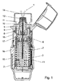
図1及び図2は、提案対象のフィルタを納めることができる手動操作式の医療用器具を略図で示している。図1及び図2に示されている器具は、推進剤なしのネブライザ(1)であり、このネブライザは、各作動サイクルにおいて所定量の液体(2)又は液体調合薬を好ましくは肺行きの又は吸入可能なエーロゾル(14)として送り出す。空力学的直径が好ましくは0.5〜10ミクロン、特に0.5〜5ミクロンの液体粒子を含むこのエーロゾル(14)は、ユーザ(図示せず)によって吸息可能である。適当なノズルが噴霧化のために用いられ、このノズルは、図示の実施形態では微細構造化コンポーネント(12)に組み込まれている。噴霧化のために用いられるこの器具のノズルを液体ディスペンサのヘッド、注入ノズル、カニューレ又は他の注入器具と交換した場合でも、ノズルとは独立した動作原理は全て、不変のままであり、その結果、以下に説明する相関関係は、説明を簡単にするためにネブライザだけに言及している場合であっても、注入器又は他の液体送り出しシステムに類似的に当てはまる。 1 and 2 schematically show a manually operated medical instrument capable of containing a proposed filter. The device shown in FIGS. 1 and 2 is a propellant-free nebulizer (1) that delivers a predetermined amount of liquid (2) or liquid preparation, preferably to the lungs or in each operating cycle. Delivered as an inhalable aerosol (14). This aerosol (14) comprising liquid particles with an aerodynamic diameter of preferably 0.5 to 10 microns, in particular 0.5 to 5 microns is inhalable by a user (not shown). A suitable nozzle is used for atomization, which is integrated in the microstructured component (12) in the illustrated embodiment. Even if the nozzle of this device used for nebulization is replaced with a liquid dispenser head, injection nozzle, cannula or other injection device, all the operating principles independent of the nozzle remain unchanged, and as a result The correlation described below applies analogously to an injector or other liquid delivery system, even if only the nebulizer is mentioned for ease of explanation.
ネブライザの作動において、圧力チャンバ(11)内の計量容積が満たされていない非引張り操作状態(図1)と圧力容器(11)が満たされている引張り操作状態(図2)とは区別される。 In the operation of the nebulizer, a distinction is made between a non-tensioning operation state (FIG. 1) in which the metering volume in the pressure chamber (11) is not filled and a tensioning operation state (FIG. 2) in which the pressure vessel (11) is filled. .
ネブライザ(1)の引張り操作中、その上側ハウジング部品(16)を内側ハウジング部品(17)及び下側ハウジング部品(18)に対して一定の回転角度、例えば180°だけ回す。内部に取り付けられた螺旋スラスト歯車が相対回転によりピストンポンプを駆動し、その結果、所定の、オプションとして調節可能な量の液体(2)が容器(3)から圧力チャンバ内に送り込まれ、それと同時に、圧力発生器(5)の駆動ばね(7)が引っ張られる(引張りプロセスの最終の状態が図2に示されている)。ネブライザ(1)を具体的にはボタン(40)を用いてロックリング(8)を操作することにより作動させると、駆動ばね(7)に蓄えられた圧力発生器(5)のエネルギーが放出される。先に液体を送り出すために用いられた中空ピストン(9)は、今や、逆止弁(10)が閉じられた状態の圧力チャンバ(11)内に入り込み、その結果、中空ピストン(9)のストローク作用によりあらかじめ定められた量の液体がここからノズルを通って放出される。この器具は、今や、再び解除状態(図1)にある。 During the pulling operation of the nebulizer (1), its upper housing part (16) is turned relative to the inner housing part (17) and the lower housing part (18) by a certain rotation angle, for example 180 °. An internally mounted helical thrust gear drives the piston pump by relative rotation, so that a predetermined, optionally adjustable amount of liquid (2) is pumped from the container (3) into the pressure chamber at the same time. The drive spring (7) of the pressure generator (5) is pulled (the final state of the pulling process is shown in FIG. 2). When the nebulizer (1) is specifically operated by operating the lock ring (8) using the button (40), the energy of the pressure generator (5) stored in the drive spring (7) is released. The The hollow piston (9) previously used to pump out liquid now enters the pressure chamber (11) with the check valve (10) closed, resulting in a stroke of the hollow piston (9). By action, a predetermined amount of liquid is discharged from here through the nozzle. The instrument is now in the released state (FIG. 1) again.
図示の実施形態では、中空ピストン(9)は、圧力発生器(5)の一部をなす容器(3)のホルダ(6)に例えば射出成形により、接着により又はスナップ嵌めにより固定的に連結されている。容器(3)は、ホルダ(6)によって、具体的に言えば、クランプ又はラッチ留め作用によってネブライザ(1)内に固定されており、中空ピストン(9)は、容器(3)の流体チャンバ内に突き出ると共に/或いは容器(3)内の液体(2)に流体結合されており、液体を中空ピストンを介して吸い込むことができる。容器は、必要に応じて交換可能であるのが良い。この目的のため、器具ハウジングは、これを開くことができるよう又は部分的に取り外すことができるよう構成されているのが良い(例えば、国際公開第07/128381(A1)号パンフレットに開示されているようにキャップ状下側ハウジング部品の形態をしている)。 In the illustrated embodiment, the hollow piston (9) is fixedly connected to the holder (6) of the container (3) forming part of the pressure generator (5), for example by injection molding, by adhesion or by snap fit. ing. The container (3) is fixed in the nebulizer (1) by means of a holder (6), in particular by clamping or latching action, and the hollow piston (9) is in the fluid chamber of the container (3). And / or fluidly coupled to the liquid (2) in the container (3) so that the liquid can be sucked in via the hollow piston. The container should be replaceable as needed. For this purpose, the instrument housing can be configured so that it can be opened or partly removed (for example disclosed in WO 07/128381 (A1)). In the form of a cap-like lower housing part).
投与量インジケータ又はカウンタ(41)を備えたネブライザ(1)中に挿入される容器(3)は、複数の投与ユニットの取り出し向きに設計されている。この理由で、容器は、内圧が液体を引き出したときでも実質的に不変のままであるよう設計されなければならず、従って、同一量の液体(2)が吸込み時に常に引き出されるようになる。これは、基本的には、例えば国際公開第06/136426(A1)号パンフレットに記載されているようにベントによって内圧が一定に保たれる剛性容器壁を備えた容器(3)と容器が取り出されているときに少なくとも部分的に容器の内部へと動き、かくして内容積を減少させることによって内圧を一定に保つ可撓性壁を備えた容器(3)の両方を用いることによって達成できる。可撓性壁が実質的に変形可能であり、圧縮可能であり且つ/或いは押し潰し可能な袋によって形成されている容器(3)が好ましい。この種の容器は、国際公開第00/49988(A2)号パンフレット、同第01/076849(A1)号パンフレット、同第99/43571(A1)号パンフレット、同第09/115200(A1)号パンフレット及び同第09/103510(A1)号パンフレットに種々の実施形態として記載されている。特に好ましくは、この容器は、底部が閉鎖されると共にグリップを形成する好ましくはプラスチック製のフランジに頂部が直接連結された柔軟性のある多層箔袋と、ネブライザ(1)のホルダ(6)に取り付け可能にこの袋に溶接された容器キャップと、外側保護スリーブと、頂部シールとから成る(詳細については、国際公開第99/43571(A1)号パンフレット及び同第09/115200(A1)号パンフレットを参照されたい)。 The container (3) inserted into the nebulizer (1) with a dose indicator or counter (41) is designed for taking out a plurality of dosing units. For this reason, the container must be designed such that the internal pressure remains substantially unchanged even when the liquid is drawn, so that the same amount of liquid (2) is always drawn upon inhalation. Basically, for example, as described in WO 06/136426 (A1) pamphlet, the container (3) having a rigid container wall whose internal pressure is kept constant by a vent and the container are taken out. This can be achieved by using both a container (3) with a flexible wall that moves at least partially into the interior of the container as it is being moved, thus keeping the internal pressure constant by reducing the internal volume. Preference is given to a container (3) in which the flexible wall is substantially deformable, compressible and / or formed by a squeezable bag. This type of container is disclosed in WO 00/49988 (A2) pamphlet, 01/0776849 (A1) pamphlet, 99/43571 (A1) pamphlet, 09/115200 (A1) pamphlet. And the 09/103510 (A1) pamphlet. Particularly preferably, the container has a flexible multilayer foil bag with the top directly connected to a preferably plastic flange that forms a grip with a closed bottom, and a holder (6) of the nebulizer (1). It consists of a container cap welded to this bag so as to be attached, an outer protective sleeve, and a top seal (for details see WO 99/43571 (A1) and 09/115200 (A1)). See).
図3は、ネブライザ(1)の圧力チャンバ(11)を概略的に示しており、この圧力チャンバは、図示の実施形態では、水性液体調合薬を噴霧化すると共に特にアルコール液体調合薬を噴霧化するのに適している。ピストンポンプシステムの一部をなす中空ピストン(9)は、容器側で圧力チャンバ(11)内に容器側のところで突き出ている。中空ピストン(9)は、圧力チャンバ(11)と容器(3)の内部との間の連結要素でもある。中空ピストン(9)が引張り操作プロセス中、圧力チャンバ(11)から部分的に引き出された場合、減圧状態が生じ、かかる減圧状態により、液体(2)は、容器(3)から吸い出され、中空ピストン(9)内の逆止弁(10)を経て圧力チャンバ(11)内に吸い込まれ、この状況では、逆止弁(10)は開いている。中空ピストン(9)がネブライザ(1)を作動させているときに圧力チャンバ(11)内に入り込むと、逆止弁(11)は、中空ピストン内の受座へのその密封面の当接によって閉じられ、圧力チャンバ(11)内の液体は、フィルタシステム及びノズルを通って圧力下で放出される。中空ピストン(9)及び圧力チャンバ(11)は、エラストマーシール(24)によって封止されており、エラストマーシール(24)は、特に、Oリングの形態をしていて、圧力チャンバ(11)内へのその入口の近くでピストンの案内管内に配置され、好ましくは支持リング(25)によって圧縮されるこのシール(24)の幾何学的取り付け位置は、例えば、国際公開第07/051536(A1)号パンフレットに記載されている位置に一致している。 FIG. 3 schematically shows the pressure chamber (11) of the nebulizer (1), which in the illustrated embodiment nebulizes an aqueous liquid formulation and in particular an alcohol liquid formulation. Suitable for doing. A hollow piston (9) forming part of the piston pump system projects into the pressure chamber (11) at the container side on the container side. The hollow piston (9) is also the connecting element between the pressure chamber (11) and the interior of the container (3). If the hollow piston (9) is partially withdrawn from the pressure chamber (11) during the pulling operation process, a reduced pressure condition occurs, which causes the liquid (2) to be sucked out of the container (3), It is sucked into the pressure chamber (11) via the check valve (10) in the hollow piston (9), and in this situation the check valve (10) is open. When the hollow piston (9) enters the pressure chamber (11) when actuating the nebulizer (1), the check valve (11) is brought into contact by its sealing surface against the seat in the hollow piston. The liquid in the pressure chamber (11) is closed and discharged under pressure through the filter system and the nozzle. The hollow piston (9) and the pressure chamber (11) are sealed by an elastomeric seal (24), which is in particular in the form of an O-ring into the pressure chamber (11). The geometric mounting position of this seal (24), which is arranged in the guide tube of the piston near its inlet and preferably compressed by the support ring (25), is, for example, WO 07/051536 (A1). It corresponds to the position described in the pamphlet.
圧力チャンバ(11)の液体出口領域にはフィルタシステムが設けられており、このフィルタシステムは、ノズルが組み込まれた好ましくは微細構造化されたコンポーネント(12)の前に配置されている。図示の新規なフィルタシステムは、前後に配置された複数個のフィルタコンポーネントから成り、これらフィルタコンポーネントは、特に、用いられるフィルタ技術が異なっている。好ましくは、個々のフィルタコンポーネントのフィルタしきい値は、各フィルタがサイズ排除の原理に従ってこの前に位置するフィルタの場合よりも小さい粒子を通すようなサイズのものである。互いに異なるフィルタ技術と分離レベルが連続して増大し又は孔径が連続して小さくなるフィルタの配列の組み合わせによって、全体として高いフィルタ容量、即ち、フィルタを完全に詰まらせることなく多量の粒子の付着が生じること及び濾過がより徹底するということが達成される。孔直径が最も大きな流路中に配置されている第1のフィルタは、大きな粒子だけを捕捉し、孔直径がこれよりも小さい次のフィルタは、小さい粒子を捕捉し、その他同様である。このように、孔径の微細なフィルタは、これが液体を完全に通過させることができない時点までは大きな粒子によっては直接的に詰まらされることはない。 A filter system is provided in the liquid outlet region of the pressure chamber (11), which is arranged in front of a preferably microstructured component (12) incorporating a nozzle. The novel filter system shown consists of a plurality of filter components arranged one after the other, which differ in particular in the filter technology used. Preferably, the filter thresholds of the individual filter components are sized such that each filter will pass smaller particles than in the preceding filter according to the principle of size exclusion. The combination of different filter technologies and filter arrangements with continuously increasing separation levels or continuously decreasing pore sizes results in a high overall filter capacity, i.e. a large amount of particles without clogging the filter completely. What happens and more thorough filtration is achieved. The first filter placed in the channel with the largest pore diameter will only capture large particles, the next filter with a smaller pore diameter will capture smaller particles, and so on. Thus, a fine pore filter is not directly clogged by large particles until such time that it cannot completely pass the liquid.
特定サイズの固体粒子の捕捉に加えて、フィルタは、オプションとして、吸着によって追加の物質を捕捉することができる。互いに異なるタイプ及び互いに異なる材料のフィルタが用いられる場合、この追加の吸着は、フィルタによって様々であろう。互いに異なるフィルタ技術の組み合わせによって、より多くの粒子、特に圧力下で変形可能な粒子も又、互いに異なる吸着効果によりそれに応じて捕捉できる。 In addition to capturing specific size solid particles, the filter can optionally capture additional material by adsorption. If different types and different materials of filters are used, this additional adsorption will vary from filter to filter. By the combination of different filter technologies, more particles, in particular particles that can be deformed under pressure, can also be captured accordingly by different adsorption effects.
粒子濾過の必要性は、特にその作動性能を保証するためにネブライザのノズルが閉塞しない状態に保たれなければならないということに鑑みてネブライザ技術において生じる。吸入可能なエーロゾルを生じさせるため、大抵のネブライザの設計では、極めて小さいノズル構造が必要であり、かかるノズル構造は、半導体製造からのリソグラフィー製造法や、スパークエロージョン(spark erosion)又はレーザ穴あけ技術のような、いわゆるマイクロシステム技術によって作られる場合が多い。 The need for particle filtration arises in nebulizer technology, particularly in view of the fact that the nebulizer nozzle must be kept unoccluded to ensure its operational performance. To produce inhalable aerosols, most nebulizer designs require very small nozzle structures, such as lithographic manufacturing methods from semiconductor manufacturing, spark erosion or laser drilling techniques. It is often made by so-called micro system technology.
図示の実施形態では、望ましいマイクロ構造化コンポーネント(12)のノズルチャネル(12d)の寸法は、ほんの数ミクロンである。好ましくは、ノズルチャネル(12d)は、2〜10ミクロンのエッジ長さを備えた長方形の輪郭形状のものである。特定の実施形態において挿入のために使用できる微細構造化コンポーネント(12)が図4に示されている。この実施形態では、ネブライザによる液体の噴霧化は、好ましくは、液体の2つのミクロ的ジェットの高速衝突を利用しており、液体ジェットは、規定された角度で交わるよう差し向けられた好ましくは2つのノズルチャネル(12d)又は関連のノズル開口部(12e)から出て、そして、衝突の際に作用する力によって噴霧化される。粒子が器具の作動中、これらノズルチャネル(12d)内に堆積した場合、液体ジェットは、方向が反らされ、場合によっては、衝突及びそれにより噴霧化がもはや完全ではなく又は極端な場合には全く起こらない場合がある。この理由で、粒子は、液体がノズルチャネル(12d)内に流れる前であっても可能な限り完全に液体(2)から濾過して除去されなければならない。 In the illustrated embodiment, the desired microstructured component (12) nozzle channel (12d) dimensions are only a few microns. Preferably, the nozzle channel (12d) is of a rectangular profile with an edge length of 2-10 microns. A microstructured component (12) that can be used for insertion in certain embodiments is shown in FIG. In this embodiment, the nebulization of the liquid preferably utilizes a high velocity impact of two microscopic jets of liquid, the liquid jet being preferably directed to meet at a defined angle. It exits from one nozzle channel (12d) or the associated nozzle opening (12e) and is atomized by the force acting upon the impact. If particles accumulate in these nozzle channels (12d) during instrument operation, the liquid jet will be deflected, and in some cases when impingement and thereby nebulization is no longer complete or extreme It may not happen at all. For this reason, the particles must be filtered out of the liquid (2) as completely as possible even before the liquid flows into the nozzle channel (12d).
液体調合薬内での凝集又はフロキュレーションや、ネブライザの組み立て中におけるプロセスステップ、そしてコンポーネントが器具内で、例えば動的シールの付近で互いに対して当たるように動くことで生じる研磨、のようにネブライザ内での粒子の発生要因は様々である。 Such as agglomeration or flocculation within a liquid formulation, process steps during assembly of the nebulizer, and polishing that occurs as components move in the instrument, for example, against each other near a dynamic seal There are various generation factors of particles in the nebulizer.
中央部品(23)は、圧力チャンバ(11)の側方境界部、液体を運搬する中空ピストン(9)の案内通路の形態をした液体入口及びフィルタがノズルの前で収容されている液体出口を形成する。図示の実施形態では、圧力チャンバは、実質的に円筒形である。好ましい実施形態におけるノズル及びポンプチャンバシステムの構成は、ポンプチャンバを構成する中央部品(23)が中空ピストン(9)側の端部のところに、好ましくは下流側の方向に僅かに円錐形に、即ち貫流方向に次第にテーパした中央ボアを有し、この中央ボアは、フィルタコンポーネントを受け入れると共に圧力チャンバ(11)を形成し、しかも中空ピストン(9)及び対応して広い箇所のところに関連シール(24)を受け入れる。下流側では、ノズルを形成する微細構造化コンポーネント(12)及び種々の関連保持又は密封コンポーネントを収容したノズル組立体(29)が中央部品(23)に取り付けられている。 The central part (23) has a lateral boundary of the pressure chamber (11), a liquid inlet in the form of a guide passage for the hollow piston (9) carrying the liquid and a liquid outlet in which a filter is accommodated in front of the nozzle. Form. In the illustrated embodiment, the pressure chamber is substantially cylindrical. The configuration of the nozzle and pump chamber system in the preferred embodiment is such that the central part (23) constituting the pump chamber is at the end on the hollow piston (9) side, preferably slightly conical in the downstream direction. That is, it has a central bore that tapers in the flow-through direction, which receives the filter component and forms a pressure chamber (11), and is associated with a hollow piston (9) and a correspondingly wide area with a corresponding seal ( 24) is accepted. Downstream, a nozzle assembly (29) containing the microstructured component (12) forming the nozzle and various associated holding or sealing components is attached to the central part (23).
好ましくは、流れ方向において圧力チャンバ(11)の後に最初に位置するフィルタコンポーネントは、粗フィルタ又は前置フィルタ(27)であり、このフィルタのすぐ次に微細フィルタ(28)が配置されている。さらに下流側には、ノズルを形成すると共に実際のノズルチャネル(12d)だけでなく一体形超微細フィルタ(12f)を収容した微細構造化コンポーネント(12)が設けられている。このように、液体は、3つの濾過コンポーネント、即ち、粗フィルタ又は前置フィルタ(27)、微細フィルタ(28)及び最後に超微細フィルタ(12f)を通って器具内を流れる。送り出された液体の粒子負荷又は必要な粒子からの自由度に基づいて、追加のフィルタ要素又は濾過材を組み込むことも又可能である。望ましい実施形態では、ノズル開口部(12e)と超微細フィルタ(12f)の両方を有するノズル又は微細構造化コンポーネント(12)は、好ましくはシリコンの微細構造化プレート(12a)及び構造体を覆う好ましくはガラスで作られたプレート(12b)で構成されている。このようにして組み込まれると共に微細構造化技術によって作られた構造体は、まず最初に、流入領域(12c)の後に流れ方向に沿って位置する流れフィルタとして設計された超微細フィルタ(12f)を形成し、次にノズルチャネル(12d)を形成する。フィルタ作用は、中実ストラット及び通路の特別な配置によって達成される。超微細通路が製造された長方形の輪郭形状を有する状態でストラットの列のジグザグ配置が特に好ましい。通路の幅は、数ミクロンに過ぎず、好ましくはサイズが最高約2ミクロンまでの粒子が液体から除去され、その後、液体は、ノズルチャネルに入り、後で、噴霧化後に吸入器のユーザによって吸息される。ノズル組立体(29)内に納められる微細構造化コンポーネント(12)又は超微細フィルタ(12f)の考えられる構造の更なる詳細は、国際公開第94/07607(A1)号パンフレット、同第99/16530(A1)号パンフレット、同第05/000476(A1)号パンフレット、同第07/101557(A2)号パンフレット及び同第08/138936(A2)号パンフレットに開示されている。 Preferably, the filter component that is initially located after the pressure chamber (11) in the flow direction is a coarse filter or a pre-filter (27), with a fine filter (28) located immediately after this filter. Further downstream, a microstructured component (12) is provided which forms a nozzle and contains not only the actual nozzle channel (12d) but also an integral ultrafine filter (12f). Thus, the liquid flows through the instrument through three filtration components: the coarse or pre-filter (27), the fine filter (28) and finally the ultrafine filter (12f). It is also possible to incorporate additional filter elements or filter media based on the particle load of the delivered liquid or the degree of freedom from the required particles. In a preferred embodiment, a nozzle or microstructured component (12) having both a nozzle opening (12e) and an ultrafine filter (12f) preferably covers the silicon microstructured plate (12a) and structure. Consists of a plate (12b) made of glass. The structure incorporated in this way and made by the microstructuring technique first has an ultrafine filter (12f) designed as a flow filter located along the flow direction after the inflow region (12c). And then the nozzle channel (12d) is formed. Filtering is achieved by a special arrangement of solid struts and passages. A zig-zag arrangement of strut rows is particularly preferred, with the ultra-fine channels having a manufactured rectangular profile. The width of the passage is only a few microns, preferably particles up to about 2 microns in size are removed from the liquid, after which the liquid enters the nozzle channel and later is inhaled by the user of the inhaler after nebulization. Breathe. Further details of the possible structure of the microstructured component (12) or the ultrafine filter (12f) contained in the nozzle assembly (29) can be found in WO 94/07607 (A1), 99/99. No. 16530 (A1) pamphlet, No. 05/000476 (A1) pamphlet, No. 07/101557 (A2) pamphlet and No. 08/138936 (A2) pamphlet.
駆動ばね(7)を備えた圧力発生器(5)、前置フィルタ(27)、微細フィルタ(28)及び微細構造化コンポーネント(12)を有するシステム全体は、好ましくは、スプレーミストの生成中、肺に入るようになった液体粒子サイズが生成されるだけでなく、スプレーミストの雲それ自体が十分長く続き、その結果、患者が呼吸をこれに容易に合わせることができるよう構成されている。0.5〜2秒、特に1〜2秒のスプレー時間が好ましい。ネブライザ内におけるフィルタシステムの選択及びフィルタしきい値は、スプレー時間の長さに影響を与える。特に、前置フィルタ(27)、微細フィルタ(28)及び超微細フィルタ(12f)の本発明のフィルタシステムでは、結果として生じる全スプレー時間の面で、本発明の高圧システムでは30〜70barの圧力降下を生じさせ、かくしてスプレー時間の延長に寄与する微細フィルタ(28)を用いることが有利であることが判明した。圧力降下は、フィルタの孔径と関連している。幾何学的形状が同一の場合、フィルタしきい値が小さければ小さいほど、即ち、孔径が小さければ小さいほど、フィルタでの圧力降下がそれだけ一層大きくなる。 The entire system comprising the pressure generator (5) with drive spring (7), pre-filter (27), fine filter (28) and microstructured component (12) is preferably during the generation of spray mist, Not only is the liquid particle size that has entered the lungs generated, but the spray mist cloud itself lasts long enough so that the patient can easily adapt breathing to it. A spraying time of 0.5 to 2 seconds, especially 1 to 2 seconds is preferred. The choice of filter system within the nebulizer and the filter threshold affect the length of spray time. In particular, in the filter system according to the invention of the prefilter (27), the fine filter (28) and the ultrafine filter (12f), in terms of the resulting total spray time, the pressure of 30 to 70 bar in the high-pressure system according to the invention. It has been found advantageous to use a fine filter (28) that causes a descent and thus contributes to an extended spray time. The pressure drop is related to the pore size of the filter. For the same geometry, the smaller the filter threshold, i.e., the smaller the pore size, the greater the pressure drop across the filter.
図示の実施形態のフィルタコンポーネントは、これらのフィルタしきい値の面で異なっているだけでなく性状、構造及び材料の面でも異なっている。器具の3つの濾過コンポーネントは、プラスチック製のフィルタ、金属製のフィルタ及び好ましくは上述したようにガラス/シリコン複合材で作られた微細構造化コンポーネントである。かくして、前置フィルタ(27)及び微細フィルタ(28)について超微細フィルタ(12f)とは異なる材料を用いることが好ましい。調合薬の大部分と化学的適合性のある、例えばポリオレフィン材料、例えばポリエチレン(PE)、ポリプロピレン(PP)又はポリテトラフルオロエチレン(PTFE)のようなプラスチックで作られた前置フィルタ(27)が特に好ましい。また、改質ポリオレフィン、例えばメタロセン‐PPで作られた前置フィルタ(27)を用いることも又可能であり、他方、この材料の特定の吸着特性を利用することができる。好ましくは、前置フィルタ(27)は、圧縮プラスチック細粒又は焼結材料、この場合、最も好ましくは焼結ポリエチレン材料から成る。微細フィルタ(28)に関し、金属製のフィルタを用いることが好ましい。図示の実施形態では、微細フィルタ(28)は、好ましくは焼結金属、詳細にはステンレス鋼の金属粒子、最も好ましくは微小有孔構造に圧縮されたチタン粒子の形態をした焼結金属から成る。例えば孔径としての直径が9〜15ミクロンのプラスチック製フィルタと開口が2ミクロンの超微細フィルタ(12f)との間の流路中では、5〜3ミクロンの比較平均した孔径を有する微細フィルタが好ましい。したがって、金属製フィルタの孔径は、孔直径が5ミクロン未満であるほど十分小さく選択される。超微細フィルタ(12f)に関し2ミクロン開口幅を有する図示の多段フィルタシステムは、極めて大きな有効物質分子又は懸濁液成分であってもこれらが流路を辿り、そして噴霧化によりユーザによって吸入されることが可能であるように構成されている。変形例では、国際公開第08/138936(A2)号パンフレットの滅菌用途について好ましい0.05ミクロンという小さい孔径又は0.2〜0.3ミクロンの孔径のいわゆる滅菌フィルタとして微細フィルタ(28)又は超微細フィルタ(12f)を用いることも可能である。この場合、流路及び圧力発生器は各々、滅菌フィルタで生じる高い圧力損失に適合するよう構成されなければならない。 The filter components of the illustrated embodiment not only differ in terms of these filter thresholds, but also differ in terms of properties, structure and materials. The three filtration components of the instrument are a plastic filter, a metal filter and a microstructured component, preferably made of a glass / silicon composite as described above. Thus, it is preferable to use a different material from the ultrafine filter (12f) for the pre-filter (27) and the fine filter (28). A pre-filter (27) made of a plastic material, eg, a plastic material such as polyethylene (PE), polypropylene (PP) or polytetrafluoroethylene (PTFE), which is chemically compatible with the majority of the drug product. Particularly preferred. It is also possible to use a prefilter (27) made of a modified polyolefin, such as metallocene-PP, while taking advantage of the specific adsorption properties of this material. Preferably, the prefilter (27) consists of a compressed plastic granule or sintered material, in this case most preferably a sintered polyethylene material. Regarding the fine filter (28), it is preferable to use a metal filter. In the illustrated embodiment, the fine filter (28) is preferably made of sintered metal, in particular stainless steel metal particles, most preferably sintered metal in the form of titanium particles compressed into a microporous structure. . For example, in a flow path between a plastic filter having a pore diameter of 9 to 15 microns and an ultrafine filter (12f) having an opening of 2 microns, a fine filter having a comparative average pore size of 5 to 3 microns is preferable. . Therefore, the pore size of the metal filter is selected to be sufficiently small that the pore diameter is less than 5 microns. The illustrated multi-stage filter system with a 2 micron aperture width for the ultrafine filter (12f) follows even the very large active substance molecules or suspension components that follow the flow path and are inhaled by the user by nebulization. Is configured to be possible. In a variant, the fine filter (28) or ultra-fine as a so-called sterilizing filter with a pore size as small as 0.05 microns or a pore size between 0.2 and 0.3 microns, which is preferred for sterilization applications in WO 08/138936 (A2). It is also possible to use a fine filter (12f). In this case, the flow path and pressure generator must each be configured to accommodate the high pressure loss that occurs in the sterile filter.
5ミクロン未満の適当な孔径のフィルタを表面のところで集塊するいわゆる飛び散り粒子から成る種類の金属粉末から焼結プロセスによって製作するのが良いことが判明した。この種の飛び散って分別された状態の金属粉末を用いることによって、特に小さい孔径を作ることができ、従って、特に好ましい孔直径が4ミクロンの金属製フィルタを製作することが可能である。飛び散り分別金属粉末としてチタンを用いること、即ち、フィルタ材料として焼結チタン金属を用いることが特に好ましい。卑金属の使用により、特に同一流体系中に存在する高級貴金属で作られたコンポーネント、例えば、一例として示されている実施形態ではネブライザ内の好ましい中空ピストン(9)が存在している場合、特にフィルタの広い表面積により腐食が迅速に生じる場合がある。液体で作動される医療システムにおいて微細フィルタ(28)としての例えばチタン、金又は白金のような貴金属の使用(チタンの使用が最も費用効果の良いオプションである)は又、これが不活性であり、かくして、大抵の医療用有効物質及び調合薬物質と化学的に適合性があるという利点を有する。このように、フィルタは、調合薬を変化させず、しかも、フィルタを調合薬によって変化させず、特に腐食させない。好ましくは、pHの範囲が3.5〜9であり、特に3.5〜6である酸性調合薬を用いる場合に特に重要であり、かかるpHの範囲は、フィルタの卑金属の腐食をもたらす場合がある。本発明において想定されるフィルタシステムは、この種の酸性調合薬の濾過に適合している。 It has been found that a filter with a suitable pore size of less than 5 microns can be produced by a sintering process from a kind of metal powder consisting of so-called scattered particles that agglomerate at the surface. By using metal powders of this type of splattered and separated state, particularly small pore sizes can be made, and it is therefore possible to produce metallic filters with a particularly preferred pore diameter of 4 microns. It is particularly preferable to use titanium as the scattering and separating metal powder, that is, to use sintered titanium metal as the filter material. Due to the use of base metals, components made of higher precious metals that are present in the same fluid system in particular, for example when there is a preferred hollow piston (9) in the nebulizer in the embodiment shown by way of example, Corrosion may occur quickly due to the large surface area. The use of noble metals such as titanium, gold or platinum as a fine filter (28) in liquid-operated medical systems (the use of titanium is the most cost-effective option) is also inert. Thus, it has the advantage of being chemically compatible with most medically active substances and pharmaceutical substances. In this way, the filter does not change the formulation, and does not change the filter with the formulation, and in particular does not corrode. Preferably, the pH range is 3.5-9, especially when using acidic preparations that are 3.5-6, such pH range may lead to corrosion of the base metal of the filter. is there. The filter system envisaged in the present invention is adapted for the filtration of this type of acidic preparation.
フィルタ材料及びフィルタ特性の特定の選択は、最後の分析において、用いられるべき液体(2)又は調合薬の特定の意図した用途又は選択及び他の物質とのその適合性で決まる。本明細書において上述した材料及び取り付けに関する概念は、既に広範な要件を含んでいる。特に、この種のフィルタシステムを備えた器具は、蒸気圧が低い物質又は例えば溶剤としてアルコール化合物を含む液体調合薬を投与するのに適している。図示の実施形態では、器具は、中央部品(23)を有し、2つのフィルタ、又は前置フィルタ(27)及び微細フィルタ(28)が同一の中央部品(23)により形成されている圧力チャンバ(11)又は計量チャンバの下流側に位置した状態でこの中央部品内に配置されている。かくして、フィルタは、圧力チャンバ(11)とノズルチャネル(12d)との間に配置されている。微細フィルタ(28)と前置フィルタ(27)又は粗フィルタの両方は、円筒形の形をしており又は少なくとも部分的に円錐形の形をしている。 The particular choice of filter material and filter characteristics will depend on the particular intended use or choice of the liquid (2) or pharmaceutical to be used and its compatibility with other substances in the final analysis. The material and attachment concepts described herein above already include a wide range of requirements. In particular, devices with this type of filter system are suitable for administering substances with low vapor pressure or liquid preparations containing, for example, alcohol compounds as solvents. In the illustrated embodiment, the instrument has a central part (23) and two pressure filters or a pre-filter (27) and a fine filter (28) are formed by the same central part (23). (11) or arranged in this central part in a state of being located downstream of the metering chamber. Thus, the filter is arranged between the pressure chamber (11) and the nozzle channel (12d). Both the fine filter (28) and the pre-filter (27) or the coarse filter are cylindrically shaped or at least partly conical.
特に好ましくは、少なくとも一方のフィルタは、円筒形の形とは僅かに異なる円錐形の状態に先細になっている側壁を備えた形状を有する。図5は、微細フィルタ(28)の特に好ましい幾何学的形状を示している。これによれば、微細フィルタ(28)は、液体入口側に、一定の円直径の形態の微細フィルタ(28)の全長の1/3〜1/2にわたって延びる円筒形の構造を有している。微細フィルタ(28)のこの円筒形領域に隣接して、円錐形領域が設けられ、従って、微細フィルタ(28)の円直径は、流路に沿って小さくなっている。微細フィルタ(28)の流れ出口のところに、微細フィルタは、この場合も又、幅の狭い又は細い円筒形の領域を有している。側壁の円筒形領域と円錐形に先細になっている領域のこの組み合わせにより、組み立てが容易になると同時に金属材料を用いた場合であっても中央部品(23)の内壁との微細フィルタの良好な密封が得られる。 Particularly preferably, at least one of the filters has a shape with a side wall that tapers in a conical shape slightly different from the cylindrical shape. FIG. 5 shows a particularly preferred geometric shape of the fine filter (28). According to this, the fine filter (28) has a cylindrical structure extending on the liquid inlet side over 1/3 to 1/2 of the entire length of the fine filter (28) having a constant circular diameter. . Adjacent to this cylindrical region of the fine filter (28) is a conical region, so that the circular diameter of the fine filter (28) decreases along the flow path. At the flow outlet of the fine filter (28), the fine filter again has a narrow or narrow cylindrical area. This combination of the cylindrical region of the side wall and the conically tapering region facilitates assembly and, at the same time, improves the fine filter with the inner wall of the central part (23) even when using a metal material. A seal is obtained.
この場合、図示していない別の実施形態によれば、前置フィルタ(27)及び/又は微細フィルタ(28)は、カップの形状をしていても良い。この種のカップ状フィルタは、カップ状構造体の開口側が圧力チャンバの方へ向くよう器具内に収納されている。前置フィルタ(27)及び/又は微細フィルタ(28)の上流側に向いたカップ構造体は、円筒形のフィルタ型と比較して著しく拡大された入口面を有し、粒子がフィルタに達したときにより多くの粒子がこの入口面に付着することができる。これは、特に多くの大きな粒子の形成が重要であるシステムにとって特に重要である。というのは、これらに関するフィルタ容量をこのように増大させることができるからである。 In this case, according to another embodiment not shown, the pre-filter (27) and / or the fine filter (28) may be in the shape of a cup. This type of cup-shaped filter is housed in the appliance so that the open side of the cup-shaped structure faces the pressure chamber. The cup structure facing the upstream side of the pre-filter (27) and / or the fine filter (28) has a significantly enlarged inlet surface compared to the cylindrical filter mold, so that the particles reach the filter. Sometimes more particles can adhere to this entrance surface. This is especially important for systems where the formation of many large particles is important. This is because the filter capacity for these can be increased in this way.
図示していない更に別の実施形態によれば、前置フィルタ(27)は、フィルタ効果が段階的であるコンポーネントの形態で微細フィルタ(28)と組み合わされるのが良い。好ましい材料の場合、フィルタセグメントは、一緒に焼結される。図示の実施形態では、2つのフィルタは、5ミリメートル未満、特に1〜2ミリメートルの寸法を有し、従って、これらフィルタを小型流体システム、例えば小型高圧ネブライザ内に容易に収納することができる。ネブライザ(1)の組み立ての際、フィルタを中央部品(23)に設けられた適当な中央ボア中に次々に挿入し、これらフィルタは、圧力チャンバ(11)の端部のところで、中央部品(23)の内壁と圧力嵌め関係をなす。かくして、前置フィルタ(27)及び微細フィルタ(28)は、これらを固定する別のコンポーネントを何ら必要としないで中央部品(23)内に保持される。圧力嵌め及び/又は摩擦ロック連結に加えて又はこれに代えて、中央部品(23)は、その内側断面の減少によってフィルタを保持することができ、従って、流れ方向におけるフィルタは、特に流れ方向に固定される。フィルタの構成材料の選択も又、フィルタが収納される状況にとっては重要であり、特に好ましくは、微細フィルタ(28)の場合、金属で作られたフィルタは、流路中において、比較的軟質のプラスチックで作られたフィルタ、この場合前置フィルタ(27)に続く。特に高圧システムに用いられる場合、これは、金属製フィルタがプラスチック製フィルタの保持機能を果たすことができるという利点を有する。中央部品に設けられた案内通路の幾何学的設計に応じて、軟質プラスチック製フィルタは、高い流体圧力下において変形し、場合によっては損傷し或いはそのぴったりと嵌合した位置から押し出される場合がある。これは、このフィルタが比較的寸法安定性のある金属製フィルタにより定位置に保持されることによって阻止される。 According to yet another embodiment not shown, the prefilter (27) may be combined with the fine filter (28) in the form of a component in which the filter effect is gradual. In the case of a preferred material, the filter segments are sintered together. In the illustrated embodiment, the two filters have dimensions of less than 5 millimeters, in particular 1-2 millimeters, so that they can be easily housed in small fluid systems such as small high pressure nebulizers. During the assembly of the nebulizer (1), the filters are inserted one after the other into a suitable central bore provided in the central part (23), which is located at the end of the pressure chamber (11). ) And press fit. Thus, the pre-filter (27) and the fine filter (28) are held in the central part (23) without requiring any other components to secure them. In addition to or instead of the press-fit and / or friction lock connection, the central part (23) can hold the filter by reducing its inner cross section, so that the filter in the flow direction is particularly in the flow direction. Fixed. The selection of the constituent material of the filter is also important for the situation in which the filter is housed, particularly preferably in the case of the fine filter (28), the filter made of metal is relatively soft in the flow path. It follows a filter made of plastic, in this case a prefilter (27). This has the advantage that the metal filter can perform the holding function of the plastic filter, especially when used in high pressure systems. Depending on the geometric design of the guide passages provided in the central part, the soft plastic filter may be deformed under high fluid pressure and in some cases may be damaged or pushed out of its close-fitting position. . This is prevented by the filter being held in place by a relatively dimensionally stable metal filter.
プラスチックで作られた中央部品(23)内に収納される場合に微細フィルタ(28)の構成材料として硬質金属、例えばチタンを選択した場合、円錐形圧縮の際、中実金属製微細フィルタ(28)は、中央部品(23)の見かけ上軟質のプラスチック材料中に押し入り、その側部のところにバイパスを作ることができないようになるという利点がある。微細フィルタ(28)が前置フィルタ(27)の前で中央部品(23)の同一の案内通路中に挿入される好ましい組み立てプロセスでは、中央部品(23)は、微細フィルタ(28)よりも見かけ上軟質であるが、前置フィルタ(27)よりも見かけ上硬質であることが有利である。前置フィルタ(27)が特に見かけ上軟質の材料、例えばPE又はPPから成る場合、側壁が硬質の中央部品内に押し込められると、側壁に対して特に締り嵌めが達成され、従って、この場合も又、バイパスの形成が阻止される。特に好ましくは、中央部品(23)は、中実の耐圧性プラスチック、例えばPEEKから成る。 When a hard metal, such as titanium, is selected as the constituent material of the fine filter (28) when housed in a central part (23) made of plastic, a solid metal fine filter (28 when conical compression is performed) ) Has the advantage that it cannot be pushed into the apparently soft plastic material of the central part (23) and a bypass can not be made at its sides. In a preferred assembly process in which the fine filter (28) is inserted into the same guiding passage of the central part (23) in front of the pre-filter (27), the central part (23) is more apparent than the fine filter (28). It is advantageous to be soft but apparently harder than the pre-filter (27). If the prefilter (27) is made of a particularly soft material, such as PE or PP, a particularly interference fit is achieved against the side wall when it is pressed into a hard central part, and therefore also in this case. Also, the formation of a bypass is prevented. Particularly preferably, the central part (23) consists of a solid pressure-resistant plastic, for example PEEK.
器具の組み立てプロセスを全体として見ると、フィルタを圧力チャンバ(11)である構成要素を通って中央部品(23)中に挿入し、挿入開口部を次に圧力発生器(5)又は特に中空ピストン(9)として構成された連結要素によって閉鎖し、その後液体(2)を容器(3)から取り出す。 Looking at the assembly process of the instrument as a whole, the filter is inserted into the central part (23) through a component which is a pressure chamber (11), and the insertion opening is then inserted into the pressure generator (5) or in particular a hollow piston. It is closed by a connecting element configured as (9), after which the liquid (2) is removed from the container (3).
別の実施形態(図面には示されていない)では、微細フィルタ(28)は、金属メッシュフィルタであるのが良く、その微細有孔構造は、いくつかのファインメッシュ(目の細かい)ネットを重ね合わせることによって作られる。これらネットは、例えば、射出成形プロセス中、中央部品(23)内に直接成形されるのが良い。変形例として、メッシュは、別個の自蔵式フィルタ要素としてプラスチック、例えばTPE、最も好ましくはエラストマー内に埋め込まれ、従って、単一のコンポーネントがフィルタだけでなく、その関連保持要素又は好ましくは密封要素を収容する。 In another embodiment (not shown in the drawings), the fine filter (28) may be a metal mesh filter, and its fine perforated structure allows several fine mesh (fine mesh) nets. Made by overlapping. These nets may be molded directly into the central part (23), for example, during the injection molding process. As a variant, the mesh is embedded as a separate self-contained filter element in a plastic, eg TPE, most preferably an elastomer, so that a single component is not only a filter, but also its associated holding element or preferably a sealing element. To accommodate.
図6〜図8は、種々の実施形態におけるノズル組立体群(29)を拡大図で示しており、フィルタシステムはノズル組立体群の前に位置している。これら実施形態は、図3に示されている実施形態と比較して、全て、前置フィルタ(27)、微細フィルタ(28)及び超微細フィルタ(12f)の追加のフィルタとして別個の吸着フィルタ(32)を有している。吸着フィルタ(32)に起因して得られる新たな観点は別にして、図3を参照して説明した観点は、これら実施形態にも当てはまる。吸着フィルタ(32)は、所望通りに前置フィルタ(27)と微細フィルタ(28)との間(図6)、又は微細フィルタ(28)と、超微細フィルタ(12f)およびノズルを備えた微細構造化コンポーネント(12)との間(図7及び図8)に配置されている。 6-8 show enlarged views of the nozzle assembly group (29) in various embodiments, with the filter system positioned in front of the nozzle assembly group. These embodiments are all compared to the embodiment shown in FIG. 3 with separate adsorption filters (additional filters of pre-filter (27), fine filter (28) and ultrafine filter (12f)). 32). Apart from the new viewpoints obtained due to the adsorption filter (32), the viewpoints described with reference to FIG. 3 also apply to these embodiments. The adsorption filter (32) is a fine filter provided between the pre-filter (27) and the fine filter (28) as desired (FIG. 6), or a fine filter (28), an ultrafine filter (12f) and a nozzle. It is arranged between the structured component (12) (FIGS. 7 and 8).
図6の実施形態では、吸着フィルタ(32)は、流れ方向で見て前置フィルタ(27)に隣接して位置している。吸着フィルタ(32)は、微細構造化コンポーネント(12)のノズルの出口のところに堆積している場合のあるサイズ範囲が100ナノメートルよりもかなり小さいナノ粒子を分離除去するのに役立つ。吸着フィルタ(32)は、酸化アルミニウムを用いてキャリヤ繊維として機能化されたガラス繊維から作られ、この吸着フィルタは、前置フィルタ(27)とサイズが最高約3〜5μmの粒子を濾過する好ましくはチタンで作られた微細フィルタ(28)との間に摩擦的に固定されている。ノズルを形成する微細構造化コンポーネント(12)は、図示の実施形態ではガラス/シリコン複合材である。微細構造化コンポーネント(12)は、関連のシール(31)を備えたホルダ(30)によってネブライザに固定されている。この微細構造化コンポーネント(12)は、ミクロ的な液体ジェットを生じさせるノズル開口部(12e)を備えたノズルだけでなく、図4に示されたジグザグ型の流れフィルタとして具体化された超微細フィルタ(12f)を有し、この微細構造化コンポーネントは、ノズルチャネル(12d)及び/又はノズル開口部(12e)の前で流路中の液体調合薬から最高約2μmのサイズまでの粒子を除去するのに役立つ。微細構造化コンポーネント(12)中のノズル及び超微細フィルタ(12f)の微細構造の連結の結果として、超微細フィルタ(12f)は、流れ方向において微細フィルタ(28)の下流側に配置されている。図6に示されているように、吸着フィルタ(32)は、インターロック且つ/或いは摩擦連結状態で2つのフィルタシステム相互間に収納されるのが良い。図示の実施形態では、吸着フィルタは、中央部品(23)内の前置フィルタ(27)と微細フィルタ(28)との間に押し込まれている。 In the embodiment of FIG. 6, the adsorption filter (32) is located adjacent to the pre-filter (27) when viewed in the flow direction. The adsorption filter (32) serves to separate and remove nanoparticles with a size range that is much smaller than 100 nanometers that may be deposited at the nozzle exit of the microstructured component (12). The adsorption filter (32) is made of glass fibers functionalized as carrier fibers using aluminum oxide, which preferably filters the prefilter (27) and particles up to about 3-5 μm in size. Is frictionally fixed between a fine filter (28) made of titanium. The microstructured component (12) forming the nozzle is a glass / silicon composite in the illustrated embodiment. The microstructured component (12) is secured to the nebulizer by a holder (30) with an associated seal (31). This microstructured component (12) is not only a nozzle with a nozzle opening (12e) that produces a microscopic liquid jet, but also an ultrafine material embodied as a zigzag flow filter as shown in FIG. With a filter (12f), this microstructured component removes particles up to about 2 μm in size from the liquid formulation in the flow path in front of the nozzle channel (12d) and / or nozzle opening (12e) To help. As a result of the connection of the nozzle in the microstructured component (12) and the microstructure of the ultrafine filter (12f), the ultrafine filter (12f) is arranged downstream of the fine filter (28) in the flow direction. . As shown in FIG. 6, the adsorption filter (32) may be housed between two filter systems in an interlocked and / or frictionally connected state. In the illustrated embodiment, the adsorption filter is pushed between the pre-filter (27) and the fine filter (28) in the central part (23).
図7及び図8の変形実施形態では、微細フィルタ(28)は、前置フィルタ(27)の下流側に配置され、吸着フィルタ(32)は、微細フィルタ(28)と超微細フィルタ(12f)との間に直接配置されている。図7及び図8に示されている好ましい実施形態では、吸着フィルタ(32)は、縁部のところが摩擦の作用で固定されたフィルタディスクとして具体化されている。好都合には、フィルタディスクの縁部は、超微細フィルタ(12f)及びノズルを有する微細構造化コンポーネント(12)のシール(31)によるかノズル組立体(29)のホルダ(30)(図8)によるか微細構造化コンポーネント(12)それ自体(図7)によるかのいずれかによって保持される。フィルタディスクの直径が微細フィルタ(28)の直径よりも大きいこと及び微細フィルタ(28)及びフィルタディスクが直接前後に配置されていることに鑑みて、吸着フィルタ(32)の縁部は、流路の外側に位置する。吸着フィルタ(32)の縁部が流路内に位置しないため、吸着フィルタ(32)のコンポーネントが使用中、バイパスを通って放出される恐れがなく、かかる放出は、リムの周りの切断縁部のところで起こる場合が多い。図7及び図8に示されている2つの取り付け状況相互間の本質的な差は、吸着フィルタ(32)の直径が、吸着フィルタが微細構造化コンポーネント(12)を構成するコンポーネント、例えばホルダ(30)及びシール(31)によって保持される場合よりも、吸着フィルタが微細構造化コンポーネント(12)によって固定される場合の方が小さいということにある。この種の微細構造化コンポーネント(12)の通常の寸法では、2通りの場合に関し、吸着フィルタが微細構造化コンポーネント(12)によって固定された場合には吸着フィルタについて約2〜5mm、好ましくは約3mmの直径が得られ、吸着フィルタがホルダ(30)及び/又はシール(31)によって固定された場合、約3〜10mm、好ましくは約6mmの直径が得られる。図8に示されている実施形態では、微細フィルタ(28)と超微細フィルタ(12f)との間に設けられた吸着フィルタ(32)は、この吸着フィルタがその縁部のところで微細構造化コンポーネント(12)のホルダ(30)によってクランプされるような直径を有する。 7 and 8, the fine filter (28) is disposed downstream of the pre-filter (27), and the adsorption filter (32) includes the fine filter (28) and the ultrafine filter (12f). Is placed directly between. In the preferred embodiment shown in FIGS. 7 and 8, the adsorption filter (32) is embodied as a filter disc fixed at the edges by the action of friction. Conveniently, the edge of the filter disk is either due to the seal (31) of the microstructured component (12) with the ultrafine filter (12f) and the nozzle or the holder (30) of the nozzle assembly (29) (FIG. 8). Or by the microstructured component (12) itself (FIG. 7). In view of the fact that the diameter of the filter disk is larger than the diameter of the fine filter (28) and that the fine filter (28) and the filter disk are arranged directly back and forth, the edge of the adsorption filter (32) Located outside of. Since the edge of the adsorption filter (32) is not located in the flow path, the components of the adsorption filter (32) are not likely to be released through the bypass during use, and such emission is a cutting edge around the rim. It often happens at The essential difference between the two mounting situations shown in FIGS. 7 and 8 is that the diameter of the adsorption filter (32) is such that the adsorption filter constitutes a microstructured component (12) such as a holder ( 30) and the case where the adsorption filter is fixed by the microstructured component (12) than it is held by the seal (31). In the normal dimensions of this type of microstructured component (12), for two cases, about 2-5 mm, preferably about 2-5 mm, for the adsorption filter when the adsorption filter is fixed by the microstructured component (12). If a diameter of 3 mm is obtained and the adsorption filter is fixed by means of a holder (30) and / or a seal (31), a diameter of about 3 to 10 mm, preferably about 6 mm, is obtained. In the embodiment shown in FIG. 8, the adsorption filter (32) provided between the fine filter (28) and the ultrafine filter (12f) has a microstructured component at the edge of the adsorption filter. It has such a diameter that it is clamped by the holder (30) of (12).
形式が互いに異なり且つ作用が互いに異なるフィルタ要素を前後に配置するという技術的思想を液体が運搬され又は輸送される多くの器具に利用できる。提案対象のネブライザ(1)が特に純粋に機械的に動作する場合がそれである。しかしながら、本明細書において提案するフィルタシステムは、液体を小出しする純粋に機械的な装置への使用には限定されない。フィルタシステムは、例えば、液体の運搬が推進ガス又は電気ポンプ、油圧ポンプ若しくは他のポンプによって作動されるシステムにも使用できる。したがって、例えば「圧力発生器」という用語は、広く解釈されなければならない。この意味において、本発明は又、種々の分野にわたって使用でき、医療分野を超えた用途であっても可能である。 The technical idea of arranging filter elements of different types and different actions in front and back can be applied to many instruments in which liquid is transported or transported. That is the case when the proposed nebulizer (1) operates particularly purely mechanically. However, the filter system proposed herein is not limited to use in purely mechanical devices that dispense liquids. The filter system can also be used, for example, in systems where the transport of liquid is actuated by a propellant gas or an electric pump, hydraulic pump or other pump. Thus, for example, the term “pressure generator” should be interpreted broadly. In this sense, the present invention can also be used in various fields and can be used beyond the medical field.
図示のネブライザは、確かに、特に吸入可能なエーロゾルとして液体調合薬を小出しするために用いられ、かかるネブライザは、水性調合薬と好ましくはアルコールの、特にエタノールの調合薬の両方を送り出すのに適している。 The illustrated nebulizer is indeed used to dispense liquid formulations, particularly as inhalable aerosols, and such nebulizers are suitable for delivering both aqueous and preferably alcohol, especially ethanol formulations. ing.
好ましくは液体調合薬の好ましい成分は、特に国際公開第09/047173(A2)号パンフレット及び同第09/115200(A1)号パンフレットに記載されており、これら国際公開を参照により引用し、これらの記載内容を本明細書の一部とする。特に、これら国際公開パンフレットに記載された流体は、溶剤、例えばエタノール等を含むかどうかを問わず水性又は非水性溶液、混合物、調合物であって良い。 Preferably, preferred components of the liquid preparation are described in WO 09/047173 (A2) and 09/115200 (A1), and these international publications are referred to by reference, and The description is made a part of this specification. In particular, the fluids described in these international pamphlets may be aqueous or non-aqueous solutions, mixtures and formulations, whether or not they contain a solvent, such as ethanol.
1 ネブライザ
2 液体
3 容器
5 圧力発生器
6 ホルダ(容器用)
7 駆動ばね
8 ロックリング
9 中空ピストン
10 逆止弁
11 圧力チャンバ
12 微細構造化コンポーネント
12a プレート
12b プレート
12c 流入領域
12d ノズルチャネル
12e ノズル開口部
12f 超微細フィルタ
14 エーロゾル
16 上側ハウジング部品
17 内側ハウジング部品
18 下側ハウジング部品
19 安全クロージャ
23 中央部品
24 シール
25 支持リング
27 前置フィルタ
28 微細フィルタ
29 ノズル組立体
30 ホルダ
31 シール
32 吸着フィルタ
40 ボタン
41 カウンタ
1
7 Drive
Claims (22)
微細フィルタ(28)が前記液体の前記流路中で前記前置フィルタ(27)と前記微細構造化コンポーネント(12)との間に更に設けられており、前記微細フィルタ(28)は、前記前置フィルタ(27)とは異なっており、前記調合薬が、前記微細構造化コンポーネント(12)に入る前に、サイズ又は性状の異なる粒子が前記前置フィルタ(27)及び前記微細フィルタ(28)に付着し、
前記前置フィルタ(27)と前記微細フィルタ(28)と超微細フィルタ(12f)とが、異なる材料から構成され、一のフィルタが焼結チタンで作られている、
ことを特徴とする器具。 A device for administering a liquid preparation, said liquid preparation being held in a container (3) inserted in said device and from said device through at least one nozzle opening (12e) The liquid formulation is released and flows through an ultrafine filter (12f) before flowing through the at least one nozzle opening (12e), the ultrafine filter being a microstructured component (12) formed by Oite with prefilter (27) inside the instrument to the microstructured component (12) before the a and that are located in the flow path of the liquid instrument,
A fine filter (28) is further provided in the liquid flow path between the pre-filter (27) and the microstructured component (12), the fine filter (28) Different from the pre-filter (27), before the drug enters the microstructured component (12), particles of different sizes or properties are introduced into the pre-filter (27) and the fine filter (28). attached to,
The pre-filter (27), the fine filter (28), and the ultrafine filter (12f) are made of different materials, and one filter is made of sintered titanium.
A device characterized by that .
請求項1〜2のうちいずれか一に記載の器具。 The fine filter (28) is made of sintered titanium;
The instrument according to any one of claims 1-2.
請求項3に記載の器具。 The fine filter made of sintered titanium consists of titanium particles compressed into a microporous structure,
The instrument of claim 3 .
請求項1〜4のうちいずれか一に記載の器具。 The pore diameter of the titanium filter is so small that the pore diameter is less than 5 microns,
The instrument according to any one of claims 1 to 4.
請求項1〜5のうちいずれか一に記載の器具。 The pre-filter (27) is a plastic filter, and the microstructured component (12) is preferably made of a glass / silicon composite,
The instrument according to any one of claims 1 to 5 .
請求項1または2に記載の器具。 The fine filter (28) is a filter whose mode of operation is mainly determined by the adsorption effect and not so much by size exclusion, and particles from the liquid flowing through the filter, particularly nanoparticles, are intermolecular. Can be deposited on the surface of the filter as a result of interaction;
The instrument according to claim 1 or 2 .
請求項1〜7のうちいずれか一に記載の器具。 An adsorption filter (32) is disposed in the flow path between the pre-filter (27) and the ultrafine filter (12f), and the mode of operation of the adsorption filter is from the liquid flowing through the filter. Characterized in that particles, in particular nanoparticles, can be deposited on the surface of the filter as a result of intermolecular interactions;
The instrument according to any one of claims 1 to 7.
請求項7または8に記載の器具。 The adsorption filter (32) is an independent component either between the prefilter (27) and the fine filter (28) or between the fine filter (28) and the ultrafine filter (12f). Arranged as
9. A device according to claim 7 or 8 .
請求項7ないし9のうちいずれか一に記載の器具。 The adsorption filter (32) is embodied as a filter disk whose edges are fixed by the action of friction,
10. A device according to any one of claims 7-9.
請求項10記載の器具。 The edge of the filter disc is either a component that seals or secures the microstructured component (12) or a nozzle in the mounting position or by the microstructured component (12) or the nozzle itself Or clamped in place between the pre-filter (27) and the fine filter (28),
The instrument of claim 10 .
請求項7〜11のうちいずれか一に記載の器具。 The adsorption filter (32) is made of glass fiber, cellulose fiber, carbon fiber or polymer fiber,
The instrument according to any one of claims 7 to 11 .
請求項7〜12のうちいずれか一に記載の器具。 The adsorption filter (32) has a surface functionalized with aluminum oxide,
The instrument according to any one of claims 7 to 12 .
請求項7〜13のうちいずれか一に記載の器具。 The adsorption filter (32) has a surface functionalized with quaternary ammonium groups,
The instrument according to any one of claims 7 to 13 .
請求項1〜14のうちいずれか一に記載の器具。 The pre-filter (27) and the fine filter (28) are cylindrical or at least partly conical,
The instrument according to any one of claims 1 to 14 .
請求項1〜15のうちいずれか一に記載の器具。 The liquid preparation to be administered comprises a low vapor pressure substance or an alcohol compound,
The instrument according to any one of claims 1 to 15 .
請求項1〜16のうちいずれか一に記載の器具。 The liquid preparation to be administered has a pH of 3.5-9,
The instrument according to any one of claims 1 to 16 .
請求項1〜17のうちいずれか一に記載の器具。 The liquid preparation is delivered as an aerosol, in particular an inhalable aerosol,
The instrument according to any one of claims 1 to 17 .
請求項1〜18のうちいずれか一に記載の器具。 The instrument has a pressure chamber (11) and the filter is arranged between the pressure chamber (11) and the at least one nozzle opening (12e) and / or nozzle channel (12b). ,
The instrument according to any one of claims 1 to 18 .
請求項1〜19のうちいずれか一に記載の器具。 The instrument has a central part (23), the pre-filter (27) and the fine filter (28) being arranged in the central part downstream of the pressure chamber (11) or metering chamber,
The instrument according to any one of claims 1 to 19 .
請求項20記載の器具。 The pre-filter (27) and the fine filter (28) are held in the central part (23) without the additional components fixing them, in particular formed by the central part itself (23). Held by a reduced internal cross-section and / or a pressure fit,
The instrument of claim 20 .
Applications Claiming Priority (5)
| Application Number | Priority Date | Filing Date | Title |
|---|---|---|---|
| EP10169883.5 | 2010-07-16 | ||
| EP10169878 | 2010-07-16 | ||
| EP10169883 | 2010-07-16 | ||
| EP10169878.5 | 2010-07-16 | ||
| PCT/EP2011/061288 WO2012007315A1 (en) | 2010-07-16 | 2011-07-05 | Filter system for use in medical devices |
Publications (3)
| Publication Number | Publication Date |
|---|---|
| JP2013530781A JP2013530781A (en) | 2013-08-01 |
| JP2013530781A5 JP2013530781A5 (en) | 2015-10-01 |
| JP5900494B2 true JP5900494B2 (en) | 2016-04-06 |
Family
ID=44546365
Family Applications (1)
| Application Number | Title | Priority Date | Filing Date |
|---|---|---|---|
| JP2013519025A Active JP5900494B2 (en) | 2010-07-16 | 2011-07-05 | Medical instrument filter system |
Country Status (4)
| Country | Link |
|---|---|
| US (2) | US9283333B2 (en) |
| EP (1) | EP2593164B1 (en) |
| JP (1) | JP5900494B2 (en) |
| WO (1) | WO2012007315A1 (en) |
Families Citing this family (15)
| Publication number | Priority date | Publication date | Assignee | Title |
|---|---|---|---|---|
| JP5900494B2 (en) | 2010-07-16 | 2016-04-06 | ベーリンガー インゲルハイム インターナショナル ゲゼルシャフト ミット ベシュレンクテル ハフツング | Medical instrument filter system |
| DE102015006766A1 (en) * | 2014-06-02 | 2015-12-03 | Mann+Hummel Gmbh | Filter system and filter element, with a glass fiber filter medium and a sintered body |
| US11701478B2 (en) | 2015-10-09 | 2023-07-18 | Boehringer Ingelheim International Gmbh | Method for coating microstructured components |
| EP3202709B1 (en) | 2016-02-04 | 2019-04-10 | Boehringer Ingelheim microParts GmbH | Moulding tool having magnetic holder |
| EP3275558B1 (en) * | 2016-07-27 | 2019-03-20 | Aptar Radolfzell GmbH | Spray assembly and dispenser with such a spray assembly, and applicator head for such a dispenser |
| CA3034556A1 (en) * | 2016-09-15 | 2018-03-22 | Softhale Nv | Valve, in particular for a device for administering a liquid medicament, and a corresponding device for administering a liquid medicament |
| JP6785374B2 (en) * | 2016-11-06 | 2020-11-18 | 微邦科技股▲ふん▼有限公司Microbase Technology Corp. | Ultrastructured passage module |
| US11793947B2 (en) | 2017-10-18 | 2023-10-24 | Softhale Nv | Seal for an inhalation device |
| NL2020671B1 (en) * | 2018-03-26 | 2019-10-02 | Medspray Bv | Spray device, spray dispensing member and spray cartridge. |
| EP3563894B1 (en) | 2018-05-04 | 2021-12-22 | Boehringer Ingelheim International GmbH | Nebulizer and container |
| CN110433361B (en) * | 2018-05-04 | 2023-01-17 | 微邦科技股份有限公司 | Microstructure nozzle |
| WO2019210515A1 (en) * | 2018-05-04 | 2019-11-07 | Microbase Technology Corp | Microstructured nozzle |
| EP3894089A1 (en) * | 2018-12-12 | 2021-10-20 | SHL Medical AG | Aerosol unit |
| WO2021160308A1 (en) * | 2020-02-13 | 2021-08-19 | Shl Medical Ag | Aerosol assembly for a medicament delivery device |
| JP2023531182A (en) * | 2020-06-26 | 2023-07-21 | ソフトハレ エヌヴイ | Reversing nozzle fixture and method |
Family Cites Families (29)
| Publication number | Priority date | Publication date | Assignee | Title |
|---|---|---|---|---|
| US3745991A (en) * | 1971-02-22 | 1973-07-17 | Champion Spark Plug Co | Environmental contamination control device |
| US4066551A (en) * | 1976-01-07 | 1978-01-03 | Dynek Corporation | Portable water filtration device |
| SG45171A1 (en) | 1990-03-21 | 1998-01-16 | Boehringer Ingelheim Int | Atomising devices and methods |
| IL107120A (en) | 1992-09-29 | 1997-09-30 | Boehringer Ingelheim Int | Atomising nozzle and filter and spray generating device |
| JP2871424B2 (en) * | 1993-05-31 | 1999-03-17 | 松下電工株式会社 | Indoor air purification device |
| EP0735852B1 (en) * | 1993-12-20 | 1999-09-22 | Biopolymerix, Inc. | Liquid dispenser for sterile solutions |
| US5490938A (en) * | 1993-12-20 | 1996-02-13 | Biopolymerix, Inc. | Liquid dispenser for sterile solutions |
| DE19536902A1 (en) | 1995-10-04 | 1997-04-10 | Boehringer Ingelheim Int | Miniature fluid pressure generating device |
| DE19742439C1 (en) | 1997-09-26 | 1998-10-22 | Boehringer Ingelheim Int | Fluid micro-filter |
| DE19808295A1 (en) | 1998-02-27 | 1999-11-11 | Boehringer Ingelheim Int | Medical fluid container |
| DE19940713A1 (en) | 1999-02-23 | 2001-03-01 | Boehringer Ingelheim Int | Diffusion resistant cartridge for storing and dosing liquids, especially for producing drug-containing inhalable aerosols, has three-shell structure with collapsible bag, container and rigid housing |
| FR2802102B1 (en) | 1999-12-08 | 2002-07-12 | Poudres & Explosifs Ste Nale | NEEDLELESS SYRINGE WITH CONSTANT SECTION EJECTION TUBE |
| US6689092B2 (en) | 2000-03-03 | 2004-02-10 | Boehringer International Gmbh | Needle-less injector of miniature type |
| DE10017443A1 (en) | 2000-04-07 | 2001-10-25 | Boehringer Ingelheim Pharma | Production of bottle with rigid outer casing and flexible lining, comprises coextrusion blow molding two coaxial tubes, material at base being compressed when mold is closed to form seam with pressure balancing slit at its center |
| DE10330370A1 (en) * | 2003-06-30 | 2005-01-20 | Boehringer Ingelheim International Gmbh | Microstructured filter with anti-evaporation device |
| MXPA05013878A (en) | 2003-06-30 | 2006-03-13 | Boehringer Ingelheim Int | Microstructured high pressure nozzle with an in-built filter function. |
| US7896264B2 (en) | 2003-06-30 | 2011-03-01 | Boehringer Ingelheim International Gmbh | Microstructured high pressure nozzle with built-in filter function |
| US20050129608A1 (en) * | 2003-12-16 | 2005-06-16 | Hiroaki Takehara | Method for producing fullerenes |
| DE102005029746B4 (en) | 2005-06-24 | 2017-10-26 | Boehringer Ingelheim International Gmbh | atomizer |
| DE102005052898A1 (en) | 2005-11-03 | 2007-05-10 | Boehringer Ingelheim Pharma Gmbh & Co. Kg | Method and device for dosing medicaments |
| EP1993736B1 (en) | 2006-03-07 | 2019-05-22 | Boehringer Ingelheim International GmbH | Swirl |
| DE102006022002A1 (en) | 2006-05-10 | 2007-11-15 | Boehringer Ingelheim International Gmbh | Atomizers and methods for atomizing fluid |
| JP5061660B2 (en) * | 2007-03-07 | 2012-10-31 | ミツミ電機株式会社 | Laser processing method and dust collector used therefor |
| DE102007023012A1 (en) | 2007-05-15 | 2008-11-20 | Boehringer Ingelheim Pharma Gmbh & Co. Kg | Atomizer and filter |
| EP2044967A1 (en) | 2007-10-01 | 2009-04-08 | Boehringer Ingelheim Pharma GmbH & Co. KG | Atomiser |
| EP2244837B1 (en) | 2008-02-19 | 2016-10-19 | Boehringer Ingelheim International Gmbh | Cartridge system |
| SG189681A1 (en) | 2008-03-17 | 2013-05-31 | Boehringer Ingelheim Int | Reservoir and nebulizer |
| EP2275160A1 (en) | 2009-07-13 | 2011-01-19 | Boehringer Ingelheim International Gmbh | High pressure chamber |
| JP5900494B2 (en) | 2010-07-16 | 2016-04-06 | ベーリンガー インゲルハイム インターナショナル ゲゼルシャフト ミット ベシュレンクテル ハフツング | Medical instrument filter system |
-
2011
- 2011-07-05 JP JP2013519025A patent/JP5900494B2/en active Active
- 2011-07-05 WO PCT/EP2011/061288 patent/WO2012007315A1/en active Application Filing
- 2011-07-05 EP EP11730632.4A patent/EP2593164B1/en active Active
- 2011-07-05 US US13/809,897 patent/US9283333B2/en active Active
-
2016
- 2016-02-01 US US15/011,906 patent/US9827382B2/en active Active
Also Published As
| Publication number | Publication date |
|---|---|
| US9283333B2 (en) | 2016-03-15 |
| EP2593164A1 (en) | 2013-05-22 |
| US20130199521A1 (en) | 2013-08-08 |
| WO2012007315A1 (en) | 2012-01-19 |
| JP2013530781A (en) | 2013-08-01 |
| US9827382B2 (en) | 2017-11-28 |
| US20160144138A1 (en) | 2016-05-26 |
| EP2593164B1 (en) | 2017-03-22 |
Similar Documents
| Publication | Publication Date | Title |
|---|---|---|
| JP5900494B2 (en) | Medical instrument filter system | |
| JP5895841B2 (en) | High pressure chamber | |
| EP1792660A1 (en) | Dispensing device | |
| JP5249752B2 (en) | Nebulizer and container | |
| CN106573117B (en) | Liquid medicament cartridge and related dispenser | |
| JP2005530535A (en) | System including nozzle and fixing means thereof | |
| US9566398B2 (en) | Atomising body, atomising device, inhaler, manufacturing method of manufacturing an atomising body and assembly method for assembling an atomising device | |
| JP6199375B2 (en) | Nebulizer | |
| US7896264B2 (en) | Microstructured high pressure nozzle with built-in filter function | |
| JP2013530781A5 (en) | ||
| US20040173211A1 (en) | Powder inhaler | |
| JP2002508232A (en) | Device and method for generating an aerosol for drug administration | |
| KR19990063707A (en) | Miniaturized arrangement for generating high pressure in the fluid to be sprayed | |
| CA2530746C (en) | Microstructured high pressure nozzle with an in-built filter function | |
| TW201004663A (en) | Inhaler | |
| WO2021203038A1 (en) | Delivery of ginsenosides to the respiratory system via electronic breath actuated droplet delivery device | |
| JP5812354B2 (en) | Inhaler | |
| JP2007517529A (en) | NOZZLE SYSTEM FOR LIQUID SUPPLEMENT DEVICE WITH NOZZLE, NOZZLE HOLDER AND / OR CHECK NUT | |
| JP4933252B2 (en) | Fine structure high pressure nozzle with built-in filter function | |
| CN113677386A (en) | Improved valve | |
| CN115361989A (en) | Inhalation device system | |
| CN117729954A (en) | Inhalation device system with counting and blocking assembly | |
| WO2017187149A1 (en) | An inhaler | |
| GB2290731A (en) | Dispensing apparatus | |
| EP1212112A1 (en) | Flow control and filtration method and apparatus |
Legal Events
| Date | Code | Title | Description |
|---|---|---|---|
| A621 | Written request for application examination |
Free format text: JAPANESE INTERMEDIATE CODE: A621 Effective date: 20140616 |
|
| A977 | Report on retrieval |
Free format text: JAPANESE INTERMEDIATE CODE: A971007 Effective date: 20150512 |
|
| A131 | Notification of reasons for refusal |
Free format text: JAPANESE INTERMEDIATE CODE: A131 Effective date: 20150518 |
|
| A524 | Written submission of copy of amendment under article 19 pct |
Free format text: JAPANESE INTERMEDIATE CODE: A524 Effective date: 20150814 |
|
| TRDD | Decision of grant or rejection written | ||
| A01 | Written decision to grant a patent or to grant a registration (utility model) |
Free format text: JAPANESE INTERMEDIATE CODE: A01 Effective date: 20160210 |
|
| A61 | First payment of annual fees (during grant procedure) |
Free format text: JAPANESE INTERMEDIATE CODE: A61 Effective date: 20160222 |
|
| R150 | Certificate of patent or registration of utility model |
Ref document number: 5900494 Country of ref document: JP Free format text: JAPANESE INTERMEDIATE CODE: R150 |
|
| R250 | Receipt of annual fees |
Free format text: JAPANESE INTERMEDIATE CODE: R250 |
|
| R250 | Receipt of annual fees |
Free format text: JAPANESE INTERMEDIATE CODE: R250 |
|
| R250 | Receipt of annual fees |
Free format text: JAPANESE INTERMEDIATE CODE: R250 |
|
| R250 | Receipt of annual fees |
Free format text: JAPANESE INTERMEDIATE CODE: R250 |
|
| R250 | Receipt of annual fees |
Free format text: JAPANESE INTERMEDIATE CODE: R250 |
|
| R250 | Receipt of annual fees |
Free format text: JAPANESE INTERMEDIATE CODE: R250 |