JP4908419B2 - Dispenser, storage device and powder dispensing method - Google Patents
Dispenser, storage device and powder dispensing method Download PDFInfo
- Publication number
- JP4908419B2 JP4908419B2 JP2007535090A JP2007535090A JP4908419B2 JP 4908419 B2 JP4908419 B2 JP 4908419B2 JP 2007535090 A JP2007535090 A JP 2007535090A JP 2007535090 A JP2007535090 A JP 2007535090A JP 4908419 B2 JP4908419 B2 JP 4908419B2
- Authority
- JP
- Japan
- Prior art keywords
- powder
- dispenser
- storage device
- duct
- rupture
- Prior art date
- Legal status (The legal status is an assumption and is not a legal conclusion. Google has not performed a legal analysis and makes no representation as to the accuracy of the status listed.)
- Active
Links
- 239000000843 powder Substances 0.000 title claims description 223
- 238000003860 storage Methods 0.000 title claims description 183
- 238000000034 method Methods 0.000 title description 7
- 239000007921 spray Substances 0.000 claims description 45
- 239000003814 drug Substances 0.000 claims description 42
- 239000002245 particle Substances 0.000 claims description 37
- 229940079593 drug Drugs 0.000 claims description 28
- 239000000203 mixture Substances 0.000 claims description 23
- GUBGYTABKSRVRQ-QKKXKWKRSA-N Lactose Natural products OC[C@H]1O[C@@H](O[C@H]2[C@H](O)[C@@H](O)C(O)O[C@@H]2CO)[C@H](O)[C@@H](O)[C@H]1O GUBGYTABKSRVRQ-QKKXKWKRSA-N 0.000 claims description 10
- 230000009172 bursting Effects 0.000 claims description 10
- 239000008101 lactose Substances 0.000 claims description 10
- 239000011888 foil Substances 0.000 claims description 8
- 239000004033 plastic Substances 0.000 claims description 6
- 229940112141 dry powder inhaler Drugs 0.000 claims description 4
- 229910052751 metal Inorganic materials 0.000 claims description 4
- 239000002184 metal Substances 0.000 claims description 4
- 239000002775 capsule Substances 0.000 claims description 2
- 238000007599 discharging Methods 0.000 claims 1
- 239000007789 gas Substances 0.000 description 129
- 239000003570 air Substances 0.000 description 20
- 238000007789 sealing Methods 0.000 description 17
- 239000010419 fine particle Substances 0.000 description 7
- 230000008901 benefit Effects 0.000 description 6
- 230000000694 effects Effects 0.000 description 6
- 210000004072 lung Anatomy 0.000 description 6
- 229910052782 aluminium Inorganic materials 0.000 description 4
- XAGFODPZIPBFFR-UHFFFAOYSA-N aluminium Chemical compound [Al] XAGFODPZIPBFFR-UHFFFAOYSA-N 0.000 description 4
- 239000000463 material Substances 0.000 description 4
- 229940098458 powder spray Drugs 0.000 description 4
- 230000004888 barrier function Effects 0.000 description 3
- 230000008021 deposition Effects 0.000 description 3
- 230000004323 axial length Effects 0.000 description 2
- 210000003123 bronchiole Anatomy 0.000 description 2
- 230000001419 dependent effect Effects 0.000 description 2
- 238000009472 formulation Methods 0.000 description 2
- 239000012528 membrane Substances 0.000 description 2
- 229940071648 metered dose inhaler Drugs 0.000 description 2
- 230000001105 regulatory effect Effects 0.000 description 2
- 230000029058 respiratory gaseous exchange Effects 0.000 description 2
- LERNTVKEWCAPOY-DZZGSBJMSA-N tiotropium Chemical compound O([C@H]1C[C@@H]2[N+]([C@H](C1)[C@@H]1[C@H]2O1)(C)C)C(=O)C(O)(C=1SC=CC=1)C1=CC=CS1 LERNTVKEWCAPOY-DZZGSBJMSA-N 0.000 description 2
- 229940110309 tiotropium Drugs 0.000 description 2
- 230000007704 transition Effects 0.000 description 2
- YFMFNYKEUDLDTL-UHFFFAOYSA-N 1,1,1,2,3,3,3-heptafluoropropane Chemical compound FC(F)(F)C(F)C(F)(F)F YFMFNYKEUDLDTL-UHFFFAOYSA-N 0.000 description 1
- LVGUZGTVOIAKKC-UHFFFAOYSA-N 1,1,1,2-tetrafluoroethane Chemical compound FCC(F)(F)F LVGUZGTVOIAKKC-UHFFFAOYSA-N 0.000 description 1
- LSLYOANBFKQKPT-DIFFPNOSSA-N 5-[(1r)-1-hydroxy-2-[[(2r)-1-(4-hydroxyphenyl)propan-2-yl]amino]ethyl]benzene-1,3-diol Chemical compound C([C@@H](C)NC[C@H](O)C=1C=C(O)C=C(O)C=1)C1=CC=C(O)C=C1 LSLYOANBFKQKPT-DIFFPNOSSA-N 0.000 description 1
- 241000237970 Conus <genus> Species 0.000 description 1
- 238000009825 accumulation Methods 0.000 description 1
- 230000002411 adverse Effects 0.000 description 1
- 239000012080 ambient air Substances 0.000 description 1
- 230000003190 augmentative effect Effects 0.000 description 1
- 230000001276 controlling effect Effects 0.000 description 1
- 238000005520 cutting process Methods 0.000 description 1
- 238000009826 distribution Methods 0.000 description 1
- 238000005553 drilling Methods 0.000 description 1
- 229960001022 fenoterol Drugs 0.000 description 1
- 239000012530 fluid Substances 0.000 description 1
- 230000001788 irregular Effects 0.000 description 1
- 239000007788 liquid Substances 0.000 description 1
- 239000008263 liquid aerosol Substances 0.000 description 1
- 230000004048 modification Effects 0.000 description 1
- 238000012986 modification Methods 0.000 description 1
- 239000002991 molded plastic Substances 0.000 description 1
- 239000002985 plastic film Substances 0.000 description 1
- 229920006255 plastic film Polymers 0.000 description 1
- 239000011148 porous material Substances 0.000 description 1
- 238000004080 punching Methods 0.000 description 1
- 210000002345 respiratory system Anatomy 0.000 description 1
- 230000000717 retained effect Effects 0.000 description 1
- 239000000126 substance Substances 0.000 description 1
- 238000011144 upstream manufacturing Methods 0.000 description 1
Images


Classifications
-
- A—HUMAN NECESSITIES
- A61—MEDICAL OR VETERINARY SCIENCE; HYGIENE
- A61J—CONTAINERS SPECIALLY ADAPTED FOR MEDICAL OR PHARMACEUTICAL PURPOSES; DEVICES OR METHODS SPECIALLY ADAPTED FOR BRINGING PHARMACEUTICAL PRODUCTS INTO PARTICULAR PHYSICAL OR ADMINISTERING FORMS; DEVICES FOR ADMINISTERING FOOD OR MEDICINES ORALLY; BABY COMFORTERS; DEVICES FOR RECEIVING SPITTLE
- A61J3/00—Devices or methods specially adapted for bringing pharmaceutical products into particular physical or administering forms
- A61J3/02—Devices or methods specially adapted for bringing pharmaceutical products into particular physical or administering forms into the form of powders
-
- A—HUMAN NECESSITIES
- A61—MEDICAL OR VETERINARY SCIENCE; HYGIENE
- A61M—DEVICES FOR INTRODUCING MEDIA INTO, OR ONTO, THE BODY; DEVICES FOR TRANSDUCING BODY MEDIA OR FOR TAKING MEDIA FROM THE BODY; DEVICES FOR PRODUCING OR ENDING SLEEP OR STUPOR
- A61M15/00—Inhalators
- A61M15/0028—Inhalators using prepacked dosages, one for each application, e.g. capsules to be perforated or broken-up
-
- A—HUMAN NECESSITIES
- A61—MEDICAL OR VETERINARY SCIENCE; HYGIENE
- A61M—DEVICES FOR INTRODUCING MEDIA INTO, OR ONTO, THE BODY; DEVICES FOR TRANSDUCING BODY MEDIA OR FOR TAKING MEDIA FROM THE BODY; DEVICES FOR PRODUCING OR ENDING SLEEP OR STUPOR
- A61M11/00—Sprayers or atomisers specially adapted for therapeutic purposes
- A61M11/001—Particle size control
- A61M11/002—Particle size control by flow deviation causing inertial separation of transported particles
-
- A—HUMAN NECESSITIES
- A61—MEDICAL OR VETERINARY SCIENCE; HYGIENE
- A61M—DEVICES FOR INTRODUCING MEDIA INTO, OR ONTO, THE BODY; DEVICES FOR TRANSDUCING BODY MEDIA OR FOR TAKING MEDIA FROM THE BODY; DEVICES FOR PRODUCING OR ENDING SLEEP OR STUPOR
- A61M11/00—Sprayers or atomisers specially adapted for therapeutic purposes
- A61M11/02—Sprayers or atomisers specially adapted for therapeutic purposes operated by air or other gas pressure applied to the liquid or other product to be sprayed or atomised
-
- A—HUMAN NECESSITIES
- A61—MEDICAL OR VETERINARY SCIENCE; HYGIENE
- A61M—DEVICES FOR INTRODUCING MEDIA INTO, OR ONTO, THE BODY; DEVICES FOR TRANSDUCING BODY MEDIA OR FOR TAKING MEDIA FROM THE BODY; DEVICES FOR PRODUCING OR ENDING SLEEP OR STUPOR
- A61M15/00—Inhalators
- A61M15/0001—Details of inhalators; Constructional features thereof
- A61M15/0003—Details of inhalators; Constructional features thereof with means for dispensing more than one drug
-
- A—HUMAN NECESSITIES
- A61—MEDICAL OR VETERINARY SCIENCE; HYGIENE
- A61M—DEVICES FOR INTRODUCING MEDIA INTO, OR ONTO, THE BODY; DEVICES FOR TRANSDUCING BODY MEDIA OR FOR TAKING MEDIA FROM THE BODY; DEVICES FOR PRODUCING OR ENDING SLEEP OR STUPOR
- A61M15/00—Inhalators
- A61M15/0001—Details of inhalators; Constructional features thereof
- A61M15/002—Details of inhalators; Constructional features thereof with air flow regulating means
-
- A—HUMAN NECESSITIES
- A61—MEDICAL OR VETERINARY SCIENCE; HYGIENE
- A61M—DEVICES FOR INTRODUCING MEDIA INTO, OR ONTO, THE BODY; DEVICES FOR TRANSDUCING BODY MEDIA OR FOR TAKING MEDIA FROM THE BODY; DEVICES FOR PRODUCING OR ENDING SLEEP OR STUPOR
- A61M15/00—Inhalators
- A61M15/0028—Inhalators using prepacked dosages, one for each application, e.g. capsules to be perforated or broken-up
- A61M15/003—Inhalators using prepacked dosages, one for each application, e.g. capsules to be perforated or broken-up using capsules, e.g. to be perforated or broken-up
- A61M15/0031—Inhalators using prepacked dosages, one for each application, e.g. capsules to be perforated or broken-up using capsules, e.g. to be perforated or broken-up by bursting or breaking the package, i.e. without cutting or piercing
-
- A—HUMAN NECESSITIES
- A61—MEDICAL OR VETERINARY SCIENCE; HYGIENE
- A61M—DEVICES FOR INTRODUCING MEDIA INTO, OR ONTO, THE BODY; DEVICES FOR TRANSDUCING BODY MEDIA OR FOR TAKING MEDIA FROM THE BODY; DEVICES FOR PRODUCING OR ENDING SLEEP OR STUPOR
- A61M15/00—Inhalators
- A61M15/0028—Inhalators using prepacked dosages, one for each application, e.g. capsules to be perforated or broken-up
- A61M15/003—Inhalators using prepacked dosages, one for each application, e.g. capsules to be perforated or broken-up using capsules, e.g. to be perforated or broken-up
- A61M15/0033—Details of the piercing or cutting means
-
- A—HUMAN NECESSITIES
- A61—MEDICAL OR VETERINARY SCIENCE; HYGIENE
- A61M—DEVICES FOR INTRODUCING MEDIA INTO, OR ONTO, THE BODY; DEVICES FOR TRANSDUCING BODY MEDIA OR FOR TAKING MEDIA FROM THE BODY; DEVICES FOR PRODUCING OR ENDING SLEEP OR STUPOR
- A61M15/00—Inhalators
- A61M15/0028—Inhalators using prepacked dosages, one for each application, e.g. capsules to be perforated or broken-up
- A61M15/0045—Inhalators using prepacked dosages, one for each application, e.g. capsules to be perforated or broken-up using multiple prepacked dosages on a same carrier, e.g. blisters
- A61M15/0046—Inhalators using prepacked dosages, one for each application, e.g. capsules to be perforated or broken-up using multiple prepacked dosages on a same carrier, e.g. blisters characterized by the type of carrier
- A61M15/0048—Inhalators using prepacked dosages, one for each application, e.g. capsules to be perforated or broken-up using multiple prepacked dosages on a same carrier, e.g. blisters characterized by the type of carrier the dosages being arranged in a plane, e.g. on diskettes
-
- A—HUMAN NECESSITIES
- A61—MEDICAL OR VETERINARY SCIENCE; HYGIENE
- A61M—DEVICES FOR INTRODUCING MEDIA INTO, OR ONTO, THE BODY; DEVICES FOR TRANSDUCING BODY MEDIA OR FOR TAKING MEDIA FROM THE BODY; DEVICES FOR PRODUCING OR ENDING SLEEP OR STUPOR
- A61M15/00—Inhalators
- A61M15/0028—Inhalators using prepacked dosages, one for each application, e.g. capsules to be perforated or broken-up
- A61M15/0045—Inhalators using prepacked dosages, one for each application, e.g. capsules to be perforated or broken-up using multiple prepacked dosages on a same carrier, e.g. blisters
- A61M15/0046—Inhalators using prepacked dosages, one for each application, e.g. capsules to be perforated or broken-up using multiple prepacked dosages on a same carrier, e.g. blisters characterized by the type of carrier
- A61M15/0051—Inhalators using prepacked dosages, one for each application, e.g. capsules to be perforated or broken-up using multiple prepacked dosages on a same carrier, e.g. blisters characterized by the type of carrier the dosages being arranged on a tape, e.g. strips
-
- A—HUMAN NECESSITIES
- A61—MEDICAL OR VETERINARY SCIENCE; HYGIENE
- A61M—DEVICES FOR INTRODUCING MEDIA INTO, OR ONTO, THE BODY; DEVICES FOR TRANSDUCING BODY MEDIA OR FOR TAKING MEDIA FROM THE BODY; DEVICES FOR PRODUCING OR ENDING SLEEP OR STUPOR
- A61M2202/00—Special media to be introduced, removed or treated
- A61M2202/06—Solids
- A61M2202/064—Powder
-
- A—HUMAN NECESSITIES
- A61—MEDICAL OR VETERINARY SCIENCE; HYGIENE
- A61M—DEVICES FOR INTRODUCING MEDIA INTO, OR ONTO, THE BODY; DEVICES FOR TRANSDUCING BODY MEDIA OR FOR TAKING MEDIA FROM THE BODY; DEVICES FOR PRODUCING OR ENDING SLEEP OR STUPOR
- A61M2205/00—General characteristics of the apparatus
- A61M2205/07—General characteristics of the apparatus having air pumping means
- A61M2205/071—General characteristics of the apparatus having air pumping means hand operated
- A61M2205/073—Syringe, piston type
-
- A—HUMAN NECESSITIES
- A61—MEDICAL OR VETERINARY SCIENCE; HYGIENE
- A61M—DEVICES FOR INTRODUCING MEDIA INTO, OR ONTO, THE BODY; DEVICES FOR TRANSDUCING BODY MEDIA OR FOR TAKING MEDIA FROM THE BODY; DEVICES FOR PRODUCING OR ENDING SLEEP OR STUPOR
- A61M2205/00—General characteristics of the apparatus
- A61M2205/82—Internal energy supply devices
- A61M2205/8218—Gas operated
- A61M2205/8225—Gas operated using incorporated gas cartridges for the driving gas
-
- A—HUMAN NECESSITIES
- A61—MEDICAL OR VETERINARY SCIENCE; HYGIENE
- A61M—DEVICES FOR INTRODUCING MEDIA INTO, OR ONTO, THE BODY; DEVICES FOR TRANSDUCING BODY MEDIA OR FOR TAKING MEDIA FROM THE BODY; DEVICES FOR PRODUCING OR ENDING SLEEP OR STUPOR
- A61M2206/00—Characteristics of a physical parameter; associated device therefor
- A61M2206/10—Flow characteristics
- A61M2206/16—Rotating swirling helical flow, e.g. by tangential inflows
Description
本発明は、請求項1又は10の前文に記載された粉末を小出しするディスペンサ、請求項34の前文に記載された貯蔵装置、及び請求項47又は50の前文に記載された粉末の小出し方法に関する。
The present invention relates to a dispenser for dispensing a powder according to the preamble of
ディスペンサ、特に吸入器により投与される粉末薬剤は、呼吸器系の特定部位を最適な状態で標的にするように構成されている。これら部位としては、鼻内通路、喉及び肺の中の種々の場所、例えば気管支、細気管支及び肺胞領域が挙げられる。薬剤を標的領域に投与できるかどうかは、とりわけ、粒子の空気力学的サイズで決まる。現在理解されるべきであると考えられるように、2μm未満の空気力学的直径を有する粒子は、肺の肺胞領域内での沈着に潜在的に最適であると考えられる。空気力学的直径が2ないし約5μmの粒子は、細気管支又は気管支領域への投与により適している場合がある。空気力学的サイズが6μm以上、より好ましくは10μm以上の粒子は、典型的には、喉頭領域、喉又は鼻内通路への投与に適している。 Powdered drugs administered by a dispenser, particularly an inhaler, are configured to optimally target a specific part of the respiratory system. These sites include intranasal passages, throat and various locations in the lung, such as the bronchial, bronchiole and alveolar regions. Whether a drug can be administered to a target area depends, among other things, on the aerodynamic size of the particles. As is now considered to be understood, particles having an aerodynamic diameter of less than 2 μm are considered potentially optimal for deposition within the alveolar region of the lung. Particles with an aerodynamic diameter of 2 to about 5 μm may be more suitable for administration to the bronchiole or bronchial region. Particles with an aerodynamic size of 6 μm or more, more preferably 10 μm or more are typically suitable for administration to the laryngeal region, throat or intranasal passage.
大抵の場合、高い吸入可能なフラクション及び高い投与効率、即ち、所望領域、特に肺の中に達するフラクションを達成することが望ましい。これは、種々の要因、特に、生じさせたスプレープルームの特性、例えばプルームの伝搬速度、粒径及びその分布状態、細かい粒子のフラクション、ガスのフラクション等で決まる。本発明では、所望のスプレープルーム特性は好ましくは、小さな粒径、直径が6μm以下の薬剤粒子の高いフラクション、低い伝搬速度、長いスプレー生成時間及び(又は)長い吸入可能時間及び(又は)或る量の粉末を小出しするのに必要な少ないガス容積量を含む。 In most cases it is desirable to achieve a high inhalable fraction and a high administration efficiency, ie a fraction that reaches the desired area, in particular the lungs. This depends on various factors, in particular the characteristics of the resulting spray plume, such as the propagation velocity of the plume, the particle size and its distribution, the fine particle fraction, the gas fraction, etc. In the present invention, the desired spray plume characteristics are preferably small particle size, high fraction of drug particles having a diameter of 6 μm or less, low propagation speed, long spray generation time and / or long inhalable time and / or Contains the small volume of gas needed to dispense a quantity of powder.
特に、本発明は、肺への薬剤の投与のための乾燥粉末吸入器に関する。多くの乾燥粉末吸入器が、市場に出ており又は提案された。2つの主要なタイプ、即ち、受動式のもの及び能動式のものがある。受動式吸入器では、粉末を解凝集し、粉末を肺に送るのに必要なエネルギーの全てが、ユーザ又は患者の呼吸により提供される。能動式吸入器では、粉末を解凝集するのを助ける追加のエネルギー源が設けられている。 In particular, the invention relates to a dry powder inhaler for the administration of drugs to the lung. Many dry powder inhalers are on the market or have been proposed. There are two main types: passive and active. In a passive inhaler, all of the energy required to deagglomerate the powder and deliver the powder to the lungs is provided by the user or patient breathing. In an active inhaler, an additional energy source is provided to help deagglomerate the powder.
大抵の粉末吸入器は、粉末が追加のエネルギー源を用いないで患者により吸入される受動式のものである。受動式吸入器に関する問題は、吸入可能なフラクション、即ち、肺に実際に入る粉末の割合が、主として、患者の呼吸に依存しているということにある。粉末の解凝集、及びこれによる吸入可能なフラクションは、吸入器を通る吸入空気の流量の関数であり、したがって、患者ごとに大きく異なっている。 Most powder inhalers are passive, where the powder is inhaled by the patient without the use of an additional energy source. The problem with passive inhalers is that the inhalable fraction, ie the proportion of powder that actually enters the lungs, is mainly dependent on the patient's breathing. The deagglomeration of the powder, and thus the inhalable fraction, is a function of the flow rate of the inhaled air through the inhaler and therefore varies greatly from patient to patient.
乾燥粉末吸入器は、一回分型装置と多数回分型吸入器に分けられる。多数回分型吸入器は、1回の投与分が個々に貯蔵される予計量型(あらかじめ計量される形式)の吸入器と、粉末投与量が吸入器内で計量される計量型吸入器とに更に分けられる。 Dry powder inhalers are divided into single dose devices and multiple dose inhalers. Multi-dose inhalers are pre-metered (pre-weighed) inhalers in which a single dose is stored individually, and metered inhalers in which the powder dose is metered in the inhaler It is further divided into
多数回分予計量型吸入器には、投与一回分を厳密な工場条件下で計量でき、粉末を大気から極めて容易に隔離できるという利点がある。多くの用途では、能動ダクト粉末は、キャリヤ、例えば乳糖と混ぜ合わされ、この乳糖は、大気からの水分を吸収する傾向があり、それにより、粉末を互いにくっ付けて解凝集するのを困難にする。 The multi-dose pre-metered inhaler has the advantage that a single dose can be metered under strict factory conditions and the powder can be isolated very easily from the atmosphere. In many applications, the active duct powder is mixed with a carrier, such as lactose, which tends to absorb moisture from the atmosphere, thereby making it difficult for the powder to stick together and deagglomerate. .
本発明は、特に、薬剤を含有し又は薬剤から成る粉末を小出しする能動式ガス動力式予計量型多数回分又は一回分ディスペンサ、例えば乾燥粉末吸入器に関する。 In particular, the present invention relates to an active gas powered pre-metered multiple dose or single dose dispenser, such as a dry powder inhaler, that dispenses a powder containing or consisting of a drug.
本発明の出発点をなす国際公開第92/12799号パンフレットは、流体の流れを細かい粒径のスプレーに変換する予計量型ディスペンサを開示しており、ダクトを通る環状の流れが、その流れの成分相互間の剪断力が流れをスプレーの状態に分解するのに十分な速度勾配をその流れの中に持つように構成されている。ダクトの断面形状は、好ましくは円形であるが、他の断面形状、例えば不定形断面又は多角形断面を利用できる。しかしながら、公知の装置及び方法は、粉末を解凝集し、所望の特性を備えた遅いスプレープルームを生じさせるには最適ではない。 WO 92/12799, the starting point of the present invention, discloses a pre-metered dispenser that converts a fluid flow into a fine particle size spray, where an annular flow through the duct is the flow of the flow. The shear force between the components is configured to have a velocity gradient in the flow sufficient to break the flow into a spray state. The cross-sectional shape of the duct is preferably circular, but other cross-sectional shapes such as an irregular cross section or a polygonal cross section can be used. However, known devices and methods are not optimal for deagglomerating the powder and producing a slow spray plume with the desired properties.
国際公開第2004/041326号パンフレットは、薬物を投与するシステムに用いられ、特に、液体エーロゾルを小出しする計量装置、即ち、いわゆる定量吸入器(MDI)用の管状ノズルを開示している。管状ノズルは、規定された長さ全体を通じて曲線状であり、この管状ノズルは、曲率半径が管状ノズルの内径の少なくとも2.5倍の湾曲部分を備えている。管状ノズルの断面は、多種多様な選択肢、例えば円形、長円形、正方形、矩形、多角形等から選択可能である。 WO 2004/041326 discloses a metering device for dispensing a liquid aerosol, ie a tubular nozzle for a so-called metered dose inhaler (MDI), which is used in a system for administering a drug. The tubular nozzle is curved throughout its defined length, and the tubular nozzle has a curved portion with a radius of curvature of at least 2.5 times the inner diameter of the tubular nozzle. The cross section of the tubular nozzle can be selected from a wide variety of options, such as circular, oval, square, rectangular, polygonal, and the like.
本発明の目的は、特に粉末の良好な解凝集及び(又は)所望のスプレープルーム特性を実現できる改良型ディスペンサ、改良型貯蔵装置及び改良型粉末小出し方法を提供することにある。 It is an object of the present invention to provide an improved dispenser, an improved storage device and an improved powder dispensing method that can achieve particularly good deagglomeration of powder and / or desired spray plume characteristics.
上記目的は、請求項1又は10記載のディスペンサ、請求項34記載の貯蔵装置又は請求項47又は50記載の方法によって達成される。好ましい実施形態は、従属形式の請求項の記載内容である。
The object is achieved by a dispenser according to
本発明の一特徴は、扁平な断面を備えたダクトを提供することにある。粉末を加圧ガスによりダクト中に送り込んで粉末を解凝集すると共に微小な粉末粒子を含むスプレーを生じさせる。扁平な断面の最も長い辺と最も短い辺の比は、少なくとも2.0である。驚くべきことに、特に粉末の所与の容積又は塊で少量のガスを用いて、円形又は準円形のダクトよりも、非常に良好な解凝集及びより微小な粒子を達成できる。この効果は、扁平な断面が所与の断面積に関し、非扁平断面よりも長い周長をもたらすということで説明できる。この長い周長の結果として、より広いダクト表面が、ガス及び粉末と接触することになり、したがって、断面積(水力直径)を変更させないで、即ち、流れ抵抗又は質量流量をそれほど変更しないで、高い剪断力に起因して良好な解凝集を達成できるようになる。 One feature of the present invention is to provide a duct having a flat cross section. The powder is pumped into the duct by pressurized gas to deagglomerate the powder and produce a spray containing fine powder particles. The ratio of the longest side to the shortest side of the flat cross section is at least 2.0. Surprisingly, very good deagglomeration and finer particles can be achieved than circular or quasi-circular ducts, especially with a small amount of gas in a given volume or mass of powder. This effect can be explained by the fact that a flat cross-section provides a longer perimeter for a given cross-sectional area than a non-flat cross-section. As a result of this long perimeter, a wider duct surface will come into contact with the gas and powder, and thus without changing the cross-sectional area (hydraulic diameter), i.e. without changing the flow resistance or mass flow rate much. Good deagglomeration can be achieved due to high shear forces.
好ましくは、扁平断面の最も長い辺と最も短い辺の比は、3ないし50、最も好ましくは約5ないし30である。このように、小さな粉末粒径を持つスプレーとしての良好な解凝集度を持つ粉末の高い出力を、比較的低いガス圧力、比較的少量のガス容積及び比較的低いガス流量で達成できる。ディスペンサは、吸入可能なフラクションが高く且つ所望のスプレープルーム特性を備えた解凝集状態の乾燥粉末のプルームを生じさせる。 Preferably, the ratio of the longest side to the shortest side of the flat cross section is 3 to 50, most preferably about 5 to 30. Thus, high power of powder with good deagglomeration as a spray with small powder particle size can be achieved with relatively low gas pressure, relatively small gas volume and relatively low gas flow rate. The dispenser produces a deflocculated dry powder plume with a high inhalable fraction and the desired spray plume characteristics.
平均粒径が5μm未満の微粉の場合、代表的には75μm×1500μmの実質的に矩形のダクトが良好に働くことが判明した。平均粒径が30μmよりも大きな粉末の場合、代表的には200μm×1500μmのダクトが、良好に働く。非円形のダクトは好ましくは、粉末の粒径に応じて20ないし1000μmの水力直径を有するべきである。このダクトは、薬剤適合性のある任意の材料で作ったものであってよく、かかる材料として、プラスチック又は金属が挙げられる。2つ以上の非円形ダクトを並列して用いてもよい。 In the case of fine powder having an average particle size of less than 5 μm, it has been found that a substantially rectangular duct of typically 75 μm × 1500 μm works well. In the case of a powder having an average particle size larger than 30 μm, a duct of 200 μm × 1500 μm typically works well. Non-circular ducts should preferably have a hydraulic diameter of 20 to 1000 μm depending on the particle size of the powder. The duct may be made of any drug compatible material, such as plastic or metal. Two or more non-circular ducts may be used in parallel.
非円形のダクトは好ましくは、水力直径(水力直径は、ダクト周長に対する4つの横断面積の比として定義される)の少なくとも5又は10倍、好ましくは10ないし60倍の長さを有する。圧力が任意所与の場合、非円形ダクトが長ければ長いほど、患者に投与される粉末はそれだけ一層遅くなる。しかしながら、ダクトが長すぎる場合、貯蔵/混合チャンバ内での速度は、混合チャンバが空にならない程度まで減少する場合がある。 Non-circular ducts preferably have a length of at least 5 or 10 times, preferably 10 to 60 times the hydraulic diameter (the hydraulic diameter is defined as the ratio of the four cross-sectional areas to the duct circumference). For any given pressure, the longer the non-circular duct, the slower the powder administered to the patient. However, if the duct is too long, the speed in the storage / mixing chamber may decrease to the extent that the mixing chamber does not empty.
特に、300kPa未満のガス圧力により粉末をダクト中に送り込んで粉末を解凝集すると共に微小な粒径を持つスプレーを生じさせる。したがって、最適なスプレープルーム特性、特に低い伝搬速度を達成できる。 In particular, the powder is fed into the duct with a gas pressure of less than 300 kPa to deagglomerate the powder and produce a spray with a fine particle size. Thus, optimal spray plume characteristics, particularly low propagation speeds, can be achieved.
口及び上気道内への粉末衝突度を最小限に抑えるためにガス及び粉末の出口速度を最小限に抑えるのが有利である。しかしながら、出口速度が高ければ高いほど、粉末はそれだけ一層良好にばらばらになる、すなわち解凝集する。これに対する一解決策は、2つ又は3つ以上の衝突ダクト又は好ましくは30°ないし180°の角度、好ましくは90°ないし150°の角度で衝突する粉末ジェットを用いることによりダクト出口のところにおけるガスと粉末の混合物の出口速度を遅くすることである。これは、本発明のもう1つの特徴である。特に、多数の、少なくとも2つの粉末スプレージェットを互いに衝突させ、即ち、これら粉末スプレージェットが互いに当たってスプレーの伝搬速度を減速すると共に(或いは)粉末を解凝集する。これは、上述したような所望のスプレープルーム特性を保つ。変形例として、漸増断面を備えるディフューザを用いると、ダクトの出口のところにおけるガス及び粉末の流れを減速させることができる。 It is advantageous to minimize gas and powder outlet velocities to minimize the degree of powder impingement into the mouth and upper airway. However, the higher the exit speed, the better the powder will break apart, ie deagglomerate. One solution to this is at the duct exit by using two or more impingement ducts or a powder jet that impinges preferably at an angle of 30 ° to 180 °, preferably 90 ° to 150 °. Slowing the exit velocity of the mixture of gas and powder. This is another feature of the present invention. In particular, a large number of at least two powder spray jets collide with each other, i.e. the powder spray jets hit each other to reduce the spray propagation speed and / or deagglomerate the powder. This maintains the desired spray plume characteristics as described above. As a variant, the use of a diffuser with an increasing cross section can slow down the flow of gas and powder at the outlet of the duct.
どのようなガスを用いてもよい。例えば、液化ガス、例えばHFA134a及びHFA227を使用できる。かかる装置では、ガスは、粉末リザーバへの連結手段を備えた計量弁を有するキャニスタ内に貯蔵される。変形例として、ピストンシリンダ装置、ベロー又は任意他のガスポンプを用いて例えば周囲空気を加圧してもよい。かかる装置は、ユーザすなわち患者が、使用に先立ってこの装置の始動準備又はプライミングを行う必要がある。さらに、圧縮ガスを使用してもよい。一回分装置の場合、圧縮空気入りの予備加圧キャニスタを使用できる。 Any gas may be used. For example, liquefied gases such as HFA 134a and HFA 227 can be used. In such a device, the gas is stored in a canister having a metering valve with means for connection to a powder reservoir. As a variant, for example ambient air may be pressurized using a piston cylinder device, bellows or any other gas pump. Such a device requires the user or patient to prepare or prime the device prior to use. In addition, compressed gas may be used. In the case of a single batch device, a pre-pressurized canister containing compressed air can be used.
貯蔵チャンバ(リザーバ)及び(又は)混合チャンバを完全に空にするのに必要なガスの容積は、粉末の容積又は質量で決まる。粉末の塊が0.1ないし50mgの場合、0.2ないし300mgのガスが必要である。例えば、平均粒径が4μmの粉末が5mgの場合、100kPaないし200kPaの状態で10ないし20cm3の圧縮空気が必要であり、この場合、空気の質量は、約20ないし60mgである。粗い粉末の場合、低い圧力、代表的には100kPaゲージ圧未満の場合に必要なガス容積はこれよりも少ない。というのは、解凝集のために必要なエネルギーが小さいからである。 The volume of gas required to completely empty the storage chamber (reservoir) and / or the mixing chamber is determined by the volume or mass of the powder. If the powder mass is 0.1 to 50 mg, 0.2 to 300 mg of gas is required. For example, if the powder having an average particle size of 4 μm is 5 mg, 10 to 20 cm 3 of compressed air is required in a state of 100 kPa to 200 kPa, and in this case, the mass of air is about 20 to 60 mg. For coarse powders, less gas volume is required at low pressures, typically below 100 kPa gauge pressure. This is because the energy required for deagglomeration is small.
粉末全てを追い出すのに必要な貯蔵チャンバ(リザーバ)及びオプションとしての混合チャンバの容積は、粉末の容積又は質量で決まる。貯蔵チャンバ及びオプションとしての混合チャンバの容積は好ましくは、粉末の投与量に応じて0.002ないし0.2cm3であることが必要である。粉末投与量が多ければ多いほど、リザーバ/混合チャンバはそれだけ一層大きいことが必要である。例えば、一回分の粉末投与量が5mgの場合、完全な混合のためには0.015ないし0.03cm3の容積が必要である。好ましくは、チャンバ容積(貯蔵チャンバ及びオプションとしての混合チャンバの容積)と粉末容積の比は、1.2ないし4であることが必要である。 The volume of the storage chamber (reservoir) and optional mixing chamber required to expel all of the powder is determined by the powder volume or mass. The volume of the storage chamber and optionally the mixing chamber should preferably be between 0.002 and 0.2 cm 3 depending on the dose of powder. The higher the powder dose, the larger the reservoir / mixing chamber needs to be. For example, if a single powder dose is 5 mg, a volume of 0.015 to 0.03 cm 3 is required for complete mixing. Preferably, the ratio of chamber volume (volume of storage chamber and optional mixing chamber) to powder volume should be 1.2 to 4.
リザーバは好ましくは、尖った縁の無い円筒形のものであることが必要である。というのは、尖った縁は、粉末堆積物を引き付ける場合があるからである。1つ又は複数のガス入口は、ガスがチャンバ表面全てをスイープしてこれら表面上への粉末の堆積を阻止するように位置決めされるのが好ましい。入口は、出口から見て最も遠くに位置するチャンバ端部、即ち、非円形ダクトの近くに配置されるのが好ましい。リザーバ及び混合チャンバ内における入口と出口の相対位置は、ガスと粉末の混合物がチャンバ内に乱流による渦を形成して解凝集度を最大にし又は滑らかな乱流の無い流れがチャンバ内に達成されるような仕方で設定されてもよい。 The reservoir should preferably be cylindrical with no sharp edges. This is because sharp edges may attract powder deposits. The gas inlet or inlets are preferably positioned so that the gas sweeps all of the chamber surfaces and prevents powder deposition on these surfaces. The inlet is preferably located near the end of the chamber located furthest from the outlet, i.e. near the non-circular duct. The relative position of the inlet and outlet in the reservoir and mixing chamber allows the gas and powder mixture to form a turbulent vortex in the chamber to maximize deagglomeration or achieve a smooth turbulent flow without any turbulence It may be set in such a way.
好ましくは、非円形ダクトの後ろの表面領域は、かかる表面上への粉末のくっ付き又は逃散を極力少なくするよう最小限に抑えられる。本発明は、吸入後において装置内に保持される粉末がほとんど無く又は全く無く、それ故に、計量された量と投与された量がほぼ同じであるという利点を有する。 Preferably, the surface area behind the non-circular duct is minimized to minimize powder sticking or escape on such surfaces. The present invention has the advantage that little or no powder is retained in the device after inhalation, and therefore the metered and dosed amounts are approximately the same.
好ましくは、非円形ダクトは、非円形ダクトの後ろに流れ絞り部の無いマウスピース入口のところに配置されるべきである。 Preferably, the non-circular duct should be placed at the mouthpiece inlet without a flow restrictor behind the non-circular duct.
ディスペンサ又は貯蔵装置は、その後に投与多数回分の粉末を小出しするように構成されているのがよい。本発明の独立した特徴によれば、各投与分は、互いに異なるダクト又はノズルを用いるのがよい。このようにすると、ダクトコーナー部内での粉末の蓄積又は閉塞は、性能に悪影響を及ぼさない。 The dispenser or storage device may then be configured to dispense multiple doses of powder. According to an independent feature of the invention, each dose may use a different duct or nozzle. In this way, the accumulation or blockage of powder in the duct corner does not adversely affect performance.
別の独立した特徴によれば、投与一回分の粉末のための貯蔵チャンバは、破裂要素又は別の感圧要素によって閉鎖されており、破裂要素又は感圧要素は、加圧ガスが破裂要素を破裂させ又は感圧要素を開いて粉末を貯蔵チャンバから放出することができるよう設計されている。特に、ガスと粉末の混合物は、ガス圧力がピーク値に達した後、好ましくは非円形のダクト、ノズル等を通るに過ぎず、この場合、混合物は、低いガス圧力により放出される。これは、感圧要素、例えば、弁、破裂要素、ダイヤフラム等を用いることにより達成できる。 According to another independent feature, the storage chamber for a single dose of powder is closed by a rupture element or another pressure sensitive element, wherein the rupture element or pressure sensitive element has a pressurized gas that blocks the rupture element. It is designed to be able to rupture or open the pressure sensitive element to release the powder from the storage chamber. In particular, the mixture of gas and powder only passes through non-circular ducts, nozzles, etc. after the gas pressure has reached its peak value, in which case the mixture is released with a low gas pressure. This can be achieved by using pressure sensitive elements such as valves, rupture elements, diaphragms and the like.
好ましくは、破裂要素は、薄いプラスチックフィルム、被覆アルミニウムフィルム又は任意他の材料で作られる。感圧要素、例えば、破裂要素は、貯蔵チャンバの前又はその後ろで、特に、粉末のための貯蔵チャンバとこれに隣接した混合チャンバとの間に配置されるのがよい。 Preferably, the rupture element is made of a thin plastic film, a coated aluminum film or any other material. The pressure sensitive element, for example the rupture element, may be arranged in front of or behind the storage chamber, in particular between the storage chamber for the powder and the adjoining mixing chamber.
好ましくは、各投与分の粉末のために、即ち、各貯蔵チャンバのために別個の感圧要素又は破裂要素が用いられる。 Preferably, a separate pressure sensitive element or rupture element is used for each dose of powder, i.e. for each storage chamber.
本発明の別の独立した特徴によれば、粉末を300kPa未満の比較的低いガス圧力でダクト又はノズル窓中へ送り込んで粉末を解凝集すると共に(或いは)スプレーを生じさせる。実験結果の示すところによれば、かかる低い圧力は、良好な解凝集を達成し、オプションとして、遅いスプレーを達成するのに十分である。 According to another independent feature of the invention, the powder is pumped into a duct or nozzle window at a relatively low gas pressure of less than 300 kPa to deagglomerate the powder and / or cause a spray. Experimental results show that such low pressure is sufficient to achieve good deagglomeration and, optionally, a slow spray.
別の独立した特徴によれば、ガスの流れは、粉末の小出し中、出口側ではなく、入口側で制限され又は制御される。これは、特に、非円形ダクトの場合に可能である。好ましくは、ガス入口は、小出し中、ガスの流れを制限し又は制御する比較的小さな断面を有する。 According to another independent feature, the gas flow is restricted or controlled at the inlet side, not at the outlet side, during powder dispensing. This is possible especially in the case of non-circular ducts. Preferably, the gas inlet has a relatively small cross section that limits or controls the flow of gas during dispensing.
別の独立した特徴によれば、ディスペンサ又は貯蔵装置は、別々の又は互いに異なる薬剤/粉末のための少なくとも2つ又は3つの別々の貯蔵チャンバを有するのがよく、かかる薬剤/粉末を次に又は同時に小出しすることができ、後者の場合、好ましくは、小出し中にのみ混合可能である。 According to another independent feature, the dispenser or storage device may have at least two or three separate storage chambers for separate or different medicament / powder, such medicament / powder being next or It is possible to dispense at the same time, in the latter case preferably mixing only during the dispensing.
本発明の別の独立した特徴によれば、少なくとも2つの粉末ジェットを衝突させることにより別々の薬剤又は粉末を混合することができる。 According to another independent feature of the invention, different medicaments or powders can be mixed by impinging at least two powder jets.
本発明の別の観点、利点及び特徴は、特許請求の範囲の記載及び好ましい実施形態についての以下の詳細な説明から明らかになろう。 Other aspects, advantages and features of the present invention will become apparent from the appended claims and the following detailed description of the preferred embodiments.
図中、同一の参照符号は、同一又は類似のコンポーネントのために用いられており、この場合、同一又は類似の特性、特徴又は利点は、説明の繰り返しを省いている場合であっても実現若しくは達成され又は実現若しくは達成可能である。さらに、互いに異なる実施形態の特徴及び観点を任意所望の仕方で組み合わせることができると共に(或いは)所望に応じて他のディスペンサ又は粉末小出し方法に使用できる。 In the drawings, the same reference numerals are used for the same or similar components, and in this case, the same or similar characteristics, features or advantages are realized or omitted even if the description is not repeated. Achieved or realizable or achievable. Furthermore, the features and aspects of the different embodiments can be combined in any desired manner and / or used in other dispenser or powder dispensing methods as desired.
図1は、本発明のディスペンサ1を縮尺通りではなく例示の目的のために概略断面で示している。ディスペンサ1は、能動式装置、特にガス動力式装置である。好ましくは、ディスペンサ1は、ユーザ又は患者(図示せず)用の吸入器、特に乾燥粉末吸入器である。
FIG. 1 shows the
ディスペンサ1は、特に少なくとも1種類の薬剤を含有し、又は1種類の薬剤から成る粉末2を小出しするよう設計されている。粉末2は、純粋な薬剤又は少なくとも2種類の薬剤の混合物であるのがよい。さらに、粉末2は、少なくとも1つの他の物質、特にキャリヤ、例えば乳糖を含有するのがよい。
The
好ましくは、粉末粒子の平均直径は、約2ないし7μm、特に6μm以下である。これは、粉末2がキャリヤ、例えば乳糖を含有していない場合に特に当てはまる。
Preferably, the average diameter of the powder particles is about 2 to 7 μm, in particular 6 μm or less. This is especially true when the
粉末2がキャリヤ、例えば乳糖及び少なくとも1種類の薬剤を含有している場合、粉末2の粒径は、20ないし300μm、特に約30ないし60μmであるのがよい。しかしながら、以下に詳細に説明する解凝集の結果として、この場合でも、スプレー3は、例えば約10μm以下の小さな粒径を有することになる場合がある。特に、薬剤を解凝集中、キャリヤから分離して、ディスペンサを吸入器として用いた場合、主として、薬剤が約2ないし6μmのその小さな粒径に起因して吸入され、大きなキャリヤが飲み込まれるようにするのがよい。代替的に又は追加的に、キャリヤの分解又は開放が、解凝集中に可能である。
If the
上述すると共に後述する上述の直径は、大方の中程度の流体力学的直径として理解されると共に(或いは)スプレー3の粒子の粒径又はフラクションに適用可能である。
The aforementioned diameters described above and below are understood as most medium hydrodynamic diameters and / or are applicable to the particle size or fraction of the
図2は、粉末2を図1に類似した非常に概略的な仕方でスプレー3として小出しする際のディスペンサ1を示している。スプレー3は、微小な(粉末)粒子から成り、即ち、好ましくは6μm以下の微小な粒径を有する。特に、スプレー3は、上述したような所望のスプレープルーム特性を有する。
FIG. 2 shows a
ディスペンサ1は、粉末2を貯蔵する貯蔵装置4を受け入れ又はこの貯蔵装置を有するように構成されている。貯蔵装置4は、ディスペンサ1に組み込まれるのがよく又はディスペンサ1の一部をなすのがよい。変形例として、貯蔵装置4は、ディスペンサ1に挿入でき又はこれに連結でき、任意的に交換できる別個の部品、特に容器、カートリッジ、ブリスタ等であってもよい。
The
ディスペンサ1又は貯蔵装置4は好ましくは、ダクト5を有し、このダクトを通って粉末2が小出しされて粉末2が解凝集されると共に(或いは)スプレー3が形成される。
The
ダクト5は、図3の概略縦断面図に示すように好ましくは出口のところに位置するノズル(絞り穴)6を有するのがよい。変形例としてノズル6又は任意他の適当なノズル構造をこれに代えて又はダクト5との任意他の組み合わせの状態で用いてもよい。
As shown in the schematic longitudinal sectional view of FIG. 3, the
ディスペンサ1は、加圧ガスを用いて粉末2をダクト5/ノズル6中へ送り込んで粉末2を解凝集すると共に(或いは)微小な粒径をもつスプレー3を生じさせる。好ましくは、ディスペンサ1は、加圧ガスを提供する手段、この実施形態では、空気ポンプ7を有し、この空気ポンプを好ましくは取っ手又はアクチュエータ8で指示されているように手動で作動でき又は操作できる。特に、空気ポンプ7は、ベローから成り又はベローにより形成される。しかしながら、空気ポンプは、ピストンシリンダ装置であってもよい。空気ポンプ7に代えて、加圧ガスを提供する手段は、例えば、ディスペンサ1に動力供給するための、即ち、粉末2を所望に応じて小出しするための加圧又は液化ガスを収容したカプセル、容器等であってもよい。
The
空気ポンプ7は、300kPa未満、特に、約50ないし200kPaのガス圧力を提供することができる。これは、好ましくは、ディスペンサ1を作動させるのに十分である。液化ガス又は加圧ガス入りの容器を用いる場合、ガス圧力は、100kPaないし約700kPaであるのがよい。この場合、圧力を好ましい圧力範囲まで減少させ又は抑制し、その後、圧力を貯蔵装置4、特にその貯蔵チャンバ10に供給するのがよい。
The
好ましくは、本明細書及び特許請求の範囲に記載された圧力の値は全て、ゲージ圧、即ち、圧力差である。全ての圧力値は、ガス貯蔵手段、例えば、加圧又は液化ガス入りの容器内の圧力又は空気ポンプ7により提供される圧力に関連し、或いは、少なくとも破裂要素が以下に説明するように破裂する前にチャンバ10,14内で且つ(或いは)ダクト5内で作用する圧力に関している。
Preferably, all pressure values mentioned in the specification and claims are gauge pressures, ie pressure differences. All pressure values are related to the pressure in a gas storage means, for example a pressurized or liquefied gas container or the pressure provided by the
ディスペンサ1は、図1及び図2に破線で指示するように、ガス流量及び(又は)圧力を調整し、抑制し且つ(或いは)制御する調整又は制御手段9、特に、弁、フローレストリクタ、毛管等を有しているが、このようにするかどうかは任意である。
The
ディスペンサ1又は貯蔵装置4は、一回の小出し操作で小出しされるべき投与一回分の粉末2を収容した少なくとも1つの貯蔵チャンバ10を有する。
The
小出しのため、ガスを圧力下でガス入口11等を経由して貯蔵チャンバ10/粉末2に供給する。好ましくは、入口11は、加圧ガスを提供する手段、即ち、特に空気ポンプ7又は調整若しくは制御手段9に連結され又は連結可能である。
For dispensing, gas is supplied under pressure to the
本実施形態では、貯蔵チャンバ10は、好ましくは、破裂要素12により覆われ又は閉鎖されている。特に、破裂要素12は、水分侵入、空気との接触等を阻止するよう貯蔵チャンバ10内の粉末2を密封している。
In this embodiment, the
ガスが貯蔵チャンバ10に供給されると、破裂要素12は、所定の圧力差及び(又は)所定の圧力増加速度に達し又はこれを超えた場合(圧力パルスの発生が生じた場合)、壊れ又は破裂する。好ましくは、破裂要素12は、300kPa未満、より好ましくは約50ないし200kPaの圧力差で且つ(或いは)0.5MPa/秒よりも高く、特に、1MPa/秒よりも高い圧力増加速度の圧力パルスで破裂するよう設計されている。
When gas is supplied to the
破裂要素12は、例えば、プラスチック又は金属で作られるのがよい。破裂要素は、特にアルミニウムの薄い箔及び(又は)任意適当なメンブレンであってもよい。
The
破裂要素12は、本発明では、平均直径が少なくとも5mm、好ましくは7mm以上の貯蔵チャンバ10の断面領域を覆っている。好ましくは、破裂要素12は、図4に参照符号13で指示するように、破裂を容易にするためにあらかじめかき傷が付けられ若しくはあらかじめ刻み目が付けられ又は少なくとも1つの弱め部分を有し、図4は、破裂要素12を備えた貯蔵チャンバ10の拡大斜視図である。特に、破裂要素12は、図4に示すように、それぞれの貯蔵チャンバ10と関連の混合チャンバ14との間に配置されている。
The
破裂要素12が破裂し又は壊れると、貯蔵チャンバ10は突然開かれ、それぞれの投与分の粉末2が小出しされ、即ち、ガスと混合され、ダクト5中へ送り込まれ、そして図2に示すようにスプレー3として放出される。
When the
ガスは、貯蔵チャンバ10内にそれぞれの流れを生じさせて粉末2の全てを出口、即ち、ダクト5中へ送り込む。混合チャンバ14は、オプションとしての破裂要素12の開放空間を形成するのがよく、従って、破裂要素12は、これが破裂すると十分に開くことができるように構成されている。
The gas creates a respective flow in the
破裂要素12は、或る特定のガス圧力(ピーク圧力)に達し又はこれを超えた場合にのみそれぞれの粉末2を小出しするために開き又は貯蔵チャンバ10を通るガスの流れを可能にする感圧要素として理解できる。しかしながら、破裂圧力にいったん達し、破裂要素12が破裂し又は感圧要素が開くと、ガスが膨張し、圧力は、著しく且つ(或いは)突然に低下して粉末2を圧力パルス中、非常に効率的にガスと混合させることができ、特に、スワール又は渦が、ガスと粉末2の混合を支援するが、粉末2は、低い、即ち比較的低いガス圧力(好ましくは、300kPa未満、特に約50ないし200kPa)で放出され、特に、ダクト5中へ送り込まれるようになる。先行技術のディスペンサにおけるガス圧力よりも著しく低いこの低ガス圧力は、それぞれ低い放出速度の実現を可能にし、従って、低い伝搬速度を持つ低速スプレー3の実現を可能にする。
The
破裂要素12の効果は又、加圧ガス等のための任意他の適当な感圧要素、特に、弁又はそれぞれ寸法決めされたリザーバによって実現でき若しくは支援でき或いは増強させることさえできることは注目されなければならない。
It should be noted that the effect of the
ガスの突然の膨張は、チャンバ10,14内でのガスと粉末2の良好な混合を保証し、次に、混合物をダクト5中へ送り込む。
The sudden expansion of the gas ensures a good mixing of the gas and the
既に述べたように、破裂要素12は、オプションに過ぎない。幾つかの場合では、破裂要素12は、不要である。その代わり、例えば粉末2を小出しする直前に開くことができる密封要素等を設けるのがよい。変形例として、貯蔵チャンバ10内の粉末2を密封するためにダクト5及び(又は)ノズル6の出口端部を閉鎖してもよい。小出し操作のためにのみ、ダクト5/ノズル6は、例えば切断、穴開け等により開かれ、すると、粉末2を放出することができる。
As already mentioned, the bursting
別の変形例によれば、ダクト5/ノズル6を適当なプラグ又はキャップで閉鎖してもよく、かかるプラグ又はキャップは、使用していない間、貯蔵チャンバ10内の粉末2を密封する。このプラグ又はキャップを、小出し操作の直前に取り外し又は小出し操作中にガス圧力により開くことができ、このプラグ又はキャップは、破裂要素12とほぼ同じ機能を有する。プラグの吸入を阻止するため、それぞれのフィルタを設け又はプラグを任意適当な仕方で別の部品に連結してプラグが完全には分離することができないようにしてもよい。
According to another variant, the
好ましくは、貯蔵装置4は、ガスと粉末2を混合する混合チャンバ14を形成する。チャンバ10,14は、好ましくは、ガスが粉末2とガスを良好に混合させるスワール又は渦を生じさせることができるように設計されている。好ましくは、チャンバ10,14は、断面が実質的に円形であり、特に、円筒形である。しかしながら、他の形状も又、採用可能である。
Preferably, the
さらに、貯蔵装置4、特にチャンバ10,14は、尖った縁部、コーナ部等が無い状態で形成されるが、ガスがチャンバ表面全てをスイープしてチャンバ表面上への粉末2の堆積を阻止すると共に粉末2の完全な放出を保証し又は可能にするよう滑らかな輪郭を有する。特に、ガス入口11は、軸方向又は出口方向に関し粉末出口、即ち、ダクト5及び(又は)ノズル6と反対側に設けられる。
Furthermore, the
貯蔵装置4は、一回分のためのたった1つの貯蔵チャンバ10を有する場合があり、この場合、貯蔵装置4は、投与一回分だけのためであり、又は、多数の貯蔵キャビティ10を有してもよく、このように、次々に小出しできる投与多数回分の粉末2を収容してもよい。
The
ディスペンサ1により提供されるガス供給源、特に空気ポンプ7を好ましくは小出し操作に必要な場合一時的にのみ任意適当な仕方でそれぞれの貯蔵装置4若しくは貯蔵チャンバ10、特にそれぞれのガス入口11に連結するのがよい。例えば、穴開け要素、連結要素等を特にこれをそれぞれの密封要素、ダイヤフラム、メンブレン、壁部分等に押し込むことによりガス入口11/それぞれの貯蔵チャンバ10に流体結合してガス供給源を開き又はそれぞれの貯蔵チャンバ10へのガス供給を可能にするのがよい。
The gas supply provided by the
図5は、貯蔵装置4又は貯蔵チャンバ10の別の実施形態を非常に概略的なスケッチで示しており、この場合、側壁、特に混合チャンバ14の側壁又は断面は、ダクト5に向かってテーパしており、その目的は、粉末2がガスの流れにもかかわらず留まる場合のある尖った縁部、コーナ部等を無くすことにある。
FIG. 5 shows another embodiment of the
本発明の一特徴によれば、ダクト5は、扁平な(内部)断面を有している。図6aないし図6cは、ダクト5の考えられる断面を示している。図6aは、実質的に矩形の断面を示している。図6bは、2つの反対側の真っ直ぐな側部が2つの湾曲した部分で連結された扁平な断面を示している。図6cは、長円形又は楕円形断面を示している。
According to one characteristic of the invention, the
本発明では、断面は、この断面の最も長い辺d1と最も短い辺d2の比が、少なくとも2.0である場合に扁平であると考えられる。好ましくは、この比は、3ないし50、特に約5ないし70である。図6に示す断面は、縮尺通りではないことが指摘される。 In the present invention, a cross-section is considered flat when the ratio of the longest side d1 to the shortest side d2 of the cross-section is at least 2.0. Preferably, this ratio is 3 to 50, in particular about 5 to 70. It is pointed out that the cross section shown in FIG. 6 is not to scale.
最も長い辺d1は、好ましくは、0.5ないし5mm、特に1ないし3mmである。最も好ましくは、最も長い辺d1と(望ましい)微小な粒径(スプレー3の粉末粒子又は薬剤粒子の大方の平均直径)の比は、500未満、好ましくは300未満、特に約30ないし300である。 The longest side d1 is preferably 0.5 to 5 mm, in particular 1 to 3 mm. Most preferably, the ratio of the longest side d1 to the (desirable) fine particle size (most average diameter of the powder particles or drug particles of the spray 3) is less than 500, preferably less than 300, especially about 30 to 300. .
最も短い辺d2は、好ましくは、0.05ないし0.5mm、特0.07ないし0.25mmである。最も好ましくは、最も短い辺d2と大方の平均的な(望ましい)微小粒径(スプレー3の粉末粒子又は薬剤粒子の大方の平均直径)の比は、50未満、好ましくは30未満、特に約3ないし20である。 The shortest side d2 is preferably 0.05 to 0.5 mm, particularly 0.07 to 0.25 mm. Most preferably, the ratio of the shortest side d2 to the most average (desired) fine particle size (most average diameter of the powder particles or drug particles of the spray 3) is less than 50, preferably less than 30, especially about 3 Thirty.
ダクト5の長さは、扁平な断面に関する長さを意味している。このように、ダクト5は、大きい方の長さ、即ち、別の断面形状及び(又は)大きな断面積を有する別の部分を有し、従って、扁平な断面を持つダクト5の部分と比較して、ガスと粉末2の混合物に対するこれら他の部分の影響が低くなるように構成されている。しかしながら、扁平断面の断面積及び(又は)形状は、ダクト5(扁平断面を持つ部分)の長さにわたり様々であってよい。このように、ダクト5の断面領域は、入口から出口までテーパし、或いはこの逆の状態にあることが可能である。
The length of the
最も好ましくは、ダクト5は、一定断面積を有し、即ち、一定の直径及び(又は)形状を持つ扁平断面の少なくとも一部分から成る。
Most preferably, the
ダクト5、即ち、扁平断面を持つ部分の長さは、3mmないし80mm、特に5ないし15mmであるのがよい。好ましくは、ダクト長さは、ダクト5の平均水力直径に適合しており、従って、ダクト5の長さと平均水力直径の比が少なくとも5、特に、約10、好ましくは20ないし60以上であるようになっており、この場合、水力直径は、ダクト周長に対する4つの断面積の比として定義される。
The length of the
好ましくは円形又は円筒形若しくは円錐形のチャンバ10,14の直径は、それぞれ投与一回分の粉末2の塊の容積で決まる。投与一回分が、例えば1ないし2mg(キャリヤを含まない純粋な薬剤)又は2ないし10mg(薬剤とキャリヤ、特に乳糖の配合物)であるのがよい。最初の場合、直径の範囲は、好ましくは、1.5ないし2.5mmである。第2の場合、直径の範囲は、好ましくは、2ないし5mmである。好ましくは、ダクト5の断面は、同様に様々である。例えば、最も短い辺d2は、第1の場合、約0.07ないし0.1mmであり、第2の場合、約0.15ないし0.25mmである。長い方の(内側)辺d1は、粉末又は粒径にはそれほど強くは依存しない。好ましくは、この大きい方の辺d1は、第1の場合、約1ないし2mmであり、第2の場合、1ないし3mmである。
The diameters of the preferably circular, cylindrical or
ダクト5の平均水力直径は、好ましくは、1mm未満、特に0.1mmないし0.6mmである。
The average hydraulic diameter of the
好ましくは、ダクト5は、成形されると共に(或いは)カバー付きの扁平な溝により形成される。
Preferably, the
ディスペンサ1又は貯蔵装置4は、一回分の粉末2を同時に小出しし、特に、小出しされる粉末2の全質量流量又は出力を増大させて所望の投与量を所望に応じ且つ(或いは)必要に応じて十分に短い時間で放出し又は小出しできるようにするための多数のダクト5を有するのがよい。
The
図7は、貯蔵装置4の別の実施形態を図5に類似した概略的な表し方で示している。この場合、2つのダクト5が1つの貯蔵チャンバ10/混合チャンバ14に関連付けられ又は連結されている。
FIG. 7 shows another embodiment of the
図8は、別の実施形態を同じような表し方で示しており、この場合、混合チャンバ14及びダクト5は、貯蔵装置4及び貯蔵チャンバ10とは別体の部品により形成されている。この別の部品は、カバー15等を形成するのがよく、この別個の部品は、ガスが供給されて粉末2が小出しする前においては、貯蔵装置4と接触状態に又は破裂要素12を覆った状態で配置される。この別個の部品は、1つだけのダクト5又は多数のダクト5を有してよく、特に、図示のように2つのダクト5を有するのがよい。多数のダクト5は、1つのダクト5が塞がれた場合であっても、ディスペンサ1が依然として働き、例えば、粉末2を依然として小出しできるという利点を有する。
FIG. 8 shows another embodiment in a similar way, in which the mixing
貯蔵装置4がそれぞれの投与分の粉末2入りの多数の貯蔵キャビティ10を有する場合、貯蔵装置4の出口側を覆う別個の部品を1つの貯蔵チャンバ10又は14から次の貯蔵チャンバに動かし、粉末2を1つの貯蔵チャンバ10から別の貯蔵チャンバへと次々と放出するのがよい。
If the
図9は、図7に類似した別の実施形態を示しているが、多数のダクト5が設けられており、これらダクトは、好ましくは、フィルタが形成されるよう一方が他方の側に直接配置され、この場合、フィルタの細孔が、ダクト5によって形成されている。
FIG. 9 shows another embodiment similar to FIG. 7, but with a number of
図10は、破裂要素12の無い貯蔵装置4の別の実施形態を示している。その代わり、貯蔵チャンバ10は、ダクト5又は任意他の適当な方法で開かれ、例えば、穴開けされてダクト5及び(又は)ノズル6に連結できる密封要素等によって閉鎖されている。この実施形態では、別個の混合チャンバ14は、不要である。その代わり、貯蔵チャンバ10は、粉末2によって完全には満たされない容積を有し、従って、ガスと粉末2を貯蔵チャンバ10内で直接混合することができ、即ち、貯蔵チャンバ10が、混合チャンバも又形成するように構成されている。
FIG. 10 shows another embodiment of the
この実施形態の別の特徴は、ガス供給及び混合チャンバ14の出口の方向が、先の実施形態の場合のように横方向である必要がないということにある。その代わり、ガス入口方向及び貯蔵チャンバ10からの出口方向は、互いに平行な平面内にあってもよいが、好ましくは、互いにオフセットすると共に(或いは)互いに平行である。
Another feature of this embodiment is that the direction of the gas supply and the exit of the mixing
図10は、既に挿入又は連結状態のダクト5を備えたディスペンサ1又は貯蔵装置4を示している。しかしながら、図5及び図7ないし図10では、空気供給源は、貯蔵チャンバ10又はその入口11にまだ連結されていない。
FIG. 10 shows the
図11は、ダクト5の別の実施形態の縦断面図である。この場合、ディスペンサ1又は特にダクト5は、出口速度を減速させ、この結果、スプレー3の伝搬速度を減速させる手段を有している。この実施形態では、速度を減速させる手段は、ダクト5の出口のところに設けられ又はこれに連結されたディフューザ16である。ディフューザ16は、出口速度を減少させるのに適した角度を有する。
FIG. 11 is a longitudinal sectional view of another embodiment of the
追加的に又は代替的に、ダクト5は、図11と同様な縦断面図である図12に示されているようにテーパした入口断面17を更に有するのがよい。テーパした断面17は、任意適当な内部輪郭を有してよく、このテーパ断面は、テーパ断面17への移行部又はテーパ断面17からダクト5への移行部のところに尖った縁部が生じるのを回避するよう湾曲しているのがよい。このテーパ入口断面17は、1つのダクト5又は多数のダクト5を備えた全ての実施形態に使用できる。これは又、図11の実施形態、即ち、出口速度を減速させる手段にも当てはまる。
Additionally or alternatively, the
図13は、速度を減速させる別の手段を備えた別のダクト構造を概略断面図で示しており、この別の手段は、多粉末ジェットスプレー衝突手段18を形成している。この手段18は、図13に指示されているように互いに衝突し、即ち、互いに打ち当たる多数の、少なくとも2つの粉末スプレージェットPを形成する。この実施形態では、ダクト5は、2つの区分5a,5bに分けられており、これら区分は、開口部又は出口が互いに傾けられていて区分5a,5bから出た粉末ジェットPが互いに傾けられて衝突するよう設計されている。例えば、分流器19又は任意の案内手段を流路中に設けて図13に示すようにダクト5の少なくとも2つの区分5a,5bを形成するのがよい。
FIG. 13 shows, in schematic cross section, another duct structure with another means for reducing the speed, which forms a multi-powder jet spray impingement means 18. This means 18 forms a large number of at least two powder spray jets P that collide with one another as indicated in FIG. In this embodiment, the
粉末ジェットP相互間の衝突角度αは、30°ないし180°、好ましくは少なくとも90°、特に約90°ないし150°である。粉末ジェットPの衝突の結果として、スプレー3の速度が減少すると共に(或いは)粉末2の解凝集が生じると共に(或いは)薬剤粒子がキャリヤから分離されると共に(或いは)スプレー3の良好な集束が得られる。これら作用効果は、衝突角度αで決まる。衝突角度αが大きいと、良好な作用効果が得られる。液体ジェットとは対照的に、90°以上の衝突角度が可能であり且つ好ましい。これら角度は、以下の実施形態にも当てはまる。
The collision angle α between the powder jets P is 30 ° to 180 °, preferably at least 90 °, in particular about 90 ° to 150 °. As a result of the impingement of the powder jet P, the speed of the
ダクト5は、好ましくは、図13に示す実施形態では、貯蔵チャンバ10/混合チャンバ14に少なくとも接線方向に連結されている。好ましくは、ダクト5は、円筒形チャンバ14の一方の軸方向端部のところで混合チャンバ14に連結され、ガス入口11は、チャンバ10の他方の軸方向端部に連結されている。特に、ガス入口11は、これ又、貯蔵チャンバ10に接線方向に連結されていて、ガスを流入させたときにスワールが生じ、スワール方向は、ダクト5を介するガスと粉末2の混合物の放出を支援し、ダクト5は、スワールの回転方向に接線方向に向いている。
The
図14は、粉末ジェット衝突手段18の別の実施形態を概略断面図で示している。この場合、2つ又は3つ以上のダクト5は、傾斜又は出口区分5cを有し、これら区分5cは、出口区分5cから噴出した粉末ジェットPが互いに衝突するよう互いに傾けられている。
FIG. 14 shows another embodiment of the powder jet impinging means 18 in a schematic cross-sectional view. In this case, two or
図15は、粉末スプレージェット衝突手段18の別の実施形態を概略断面図で示している。この場合、ダクト5は、全体として互いに傾けられていて、粉末ジェットPの設計された衝突を達成するように構成されている。図示のように、傾斜ダクト5の入口が関連の混合チャンバ14又は貯蔵チャンバ10の側壁のところで開口することが可能である。オプションとしての分流器19を混合チャンバ14又は貯蔵チャンバ10内に設けて所望の流れ及びガスと粉末2の混合を保証するのがよい。
FIG. 15 shows a schematic cross-sectional view of another embodiment of the powder spray jet impinging means 18. In this case, the
図13ないし図15の実施形態は又、3つ以上の粉末ジェットPを衝突させるのにも適している。例えば、同様な構造を図面の平面に垂直な断面平面内に設け、その結果、4つの出口方向及びコーヌス(conus)の平面上に配置された粉末ジェットPが得られるようにすることが可能である。しかしながら、ほぼ同じ作用効果を持つ多数の他の構造が使用可能である。 The embodiment of FIGS. 13 to 15 is also suitable for impinging three or more powder jets P. For example, it is possible to provide a similar structure in a cross-sectional plane perpendicular to the plane of the drawing so that a powder jet P is obtained which is arranged in four exit directions and in the plane of the conus. is there. However, many other structures with approximately the same effect can be used.
付け加えられるべきこととして、ダクト区分5aないし5cの断面が好ましくは扁平ではなく、任意適当な断面形状を有してよい。
It should be added that the cross section of the
別の(図示していない)実施形態によれば、ダクト5は、粉末2のリザーバ(貯蔵チャンバ10)としても使用できる。この場合、別個の貯蔵チャンバ10と混合チャンバ14は、不要である。この場合、ダクト5は、ガスと粉末2の十分な混合及び粉末2の十分な解凝集を可能にするよう設計される。
According to another (not shown) embodiment, the
好ましくは、ガス入口11又はガス供給源は、ダクト5又はノズル6よりも小さな横断面積を有し、従って、ガスの流量が、小出し中、出口側ではなく、即ち、ダクト5又はノズル6によってではなく入口によって定められるようになる。この結果、圧力は、破裂要素12又は別の感圧要素が開く直前において小出し操作の開始時にピーク値に達する。破裂要素12又は任意他の感圧要素を開いた状態で、突然の圧力減少の結果として、ガスと粉末2が貯蔵チャンバ10及び混合チャンバ14内で極めて良好且つ迅速に混ざり合う。次に、ガスと粉末2の混合物は、既に低くなっているガス圧力によってダクト5及び(又は)任意他の適当な出口、例えばノズル6中へ送り込まれ、ここで、ガス流量は、この段階中、少なくとも主としてガス入口11又はガス入口11の上流側の任意他の絞り穴の断面によって制御される。粉末2をダクト5及び(又は)ノズル6中へ放出するガス圧力が比較的低いので、スプレー3の低い放出速度及び、したがって低い伝搬速度を達成できる。粉末2の良好な解凝集は、ダクト5の扁平な断面、更にダクト5内の比較的低い放出速度により達成できる。さらに、スプレー3の伝搬速度を減速させる手段、特に、ディフューザ16又は粉末ジェット衝突手段18を用いると、スプレー3の伝搬速度を一段と減少させることができる。
Preferably, the
好ましくは、スプレー3は、2m/秒未満、特に1m/秒未満の平均速度(出口/マウスピースから10cmのところで測定された)を有する。好ましくは、スプレー3の平均持続時間は、少なくとも0.2又は0.3秒、特に約0.5ないし2秒である。
Preferably, the
図16は、多数の貯蔵キャビティ10を備えたディスペンサ1又は貯蔵装置4の別の実施形態を示している。特に、貯蔵装置4は、円板であり、貯蔵キャビティ10は、互いに間隔を置いた状態で円板の周囲に沿って好ましくは半径方向の向きで位置決めされ、従って、関連の混合チャンバ14が半径方向外方に且つ(或いは)貯蔵キャビティ10に隣接して位置決めされると共にそれぞれの破裂要素12によって互いに分けられるように構成されている。
FIG. 16 shows another embodiment of the
円板は、成形プラスチックのものであってもよく、又は任意他の適当な仕方で作られたものであってもよく、若しくは任意他の適当な材料のものであってよい。貯蔵キャビティ10及び(又は)混合チャンバ14は、円筒形又は円錐形の形態を有するのがよい。破裂要素12は、好ましくは円板状であり、例えば円錐形ホルダ20等により定位置に固定されてそれぞれの貯蔵チャンバ10を好ましくは半径方向に覆っている。ホルダ20を例えば外側リング21等により固定するのがよい。
The disc may be of molded plastic, or made in any other suitable manner, or may be of any other suitable material. The
図16は、上部カバーが設けられておらず又は貯蔵キャビティ10及び混合チャンバ14を覆って図面で見て上からこれらを閉鎖する透明なカバーを備えた状態で円板を示している。しかしながら、ガス入口11及びダクト5又は他の適当な出口ポートは、カバー及び(又は)円板に形成され又は図16に示すようにちょうど小出し操作のために挿入される。変形例として、円板にはそれぞれ入口ポート及び(又は)ポートが形成される。一回分の粉末2を小出しするため、ガス入口11又はそれぞれの連結要素及びダクト5又はそれぞれの連結要素を密封カバーを介してそれぞれのポート内に押し込む。次に、ガス供給源を開き又は空気ポンプ7を作動させ、破裂要素12が破裂し、ガス圧力がガス粉末混合物を連結状態のダクト5及び(又は)ノズル6中へ送り込む。その後又は次の小出し操作の直前に、円板を次の位置まで回転させる。
FIG. 16 shows the disc without a top cover or with a transparent cover covering the
図17は、多数の粉末リザーバ(貯蔵キャビティ10)を備えた同様なディスペンサ1又は貯蔵装置4の部分軸方向断面を示している。好ましくは、このディスペンサ1又は貯蔵装置4は、幾つかの層又は円板が軸方向に互いに上下に配置された円形又は円筒形の構造体である。粉末2は、大気湿度から完全に隔離され(これは、各実施形態に当てはまる)、この結果、乾燥状態に保たれる。
FIG. 17 shows a partial axial section of a
図示の実施形態では、好ましくは箔で作られ、特に薄い被覆アルミニウム箔で作られた第1の密封層22が、湿度バリヤとして働き、軸方向一方の側部でそれぞれの貯蔵キャビティ10内の粉末2を覆う。貯蔵キャビティ10は、例えばプラスチックで作られた第1の円板23に形成されるのがよい。第1の密封層22は、好ましくは、第1の円板23に結合されている。他方の側では、第2の密封層24が、第1の円板23に結合され、貯蔵キャビティ10をこの他方の側から覆い、このようにして、破裂要素12を形成している。第2の層24も又、好ましくは、箔、特に薄い被覆アルミニウム箔等であり、貯蔵キャビティ10内の粉末2を隔離する第2の湿度バリヤとして働く。
In the illustrated embodiment, a
第2の密封層24は、混合チャンバ14をそれぞれ形成する凹部を備えた第2の円板25により覆われるのがよく、混合チャンバ14は、第2の密封層24により分離された関連の貯蔵キャビティ10の上方に軸方向に配置されている。
The
混合チャンバ24を覆うフィルタ層26又は任意他の適当なカバーを第2の円板に結合するのがよい。この層26又はカバーは、ダクト5、ノズル6又は任意他の適当な出口手段、例えばメッシュを直接形成してもよく、或いは小出し操作のために層26を介して混合チャンバ14内にそれぞれ挿入できる出口要素、例えばダクト5の支持体及び(又は)シールであってもよい。
A
第3の円板27を第1の円板23と反対側で第1の密封層22に結合するのがよい。この第3の円板27は、例えばプラスチックで作られるのがよく、この第3の円板は、ガス入口11を形成する凹部等を有する。これらガス入口11は、好ましくは、軸方向ガス供給ではなく、横方向又は接線方向ガス供給が可能であるように貯蔵キャビティ10に対してずらされている。
The
軟質密封要素28が、好ましくは、ガス入口11と対向して第1の円板23内に設けられている。小出し操作のため、ガス供給要素29又は任意他の適当な要素を1つのガス入口11内に押し込み、そして第1の密封層22を通って押し込んで、ついには、対応の軟質密封要素28が十分に変形して関連の(隣接の)貯蔵チャンバ10内へのガスの流入が可能になる。ガス供給源が開かれ、例えば調整若しくは制御手段9又は空気ポンプ7が作動されて圧力がピークレベルに達すると、第2の層24及びガスと粉末の混合物により形成されたそれぞれの破裂要素12が、フィルタ層26又は任意他の適当な出力要素、例えばダクト5又はノズル6中へ押し込まれる。
A
指摘されなければならないこととして、第3の円板27は、オプションである。例えば、ガス入口11を特に第1の密封層22と軟質密封要素28との間で第1の円板23に形成してもよく、或いは省いてもよい。
It should be pointed out that the
さらに、図18a及び図18bの別の実施形態で示されているように、貯蔵チャンバ10の壁を直接穴開けし又は開放することが可能である。ディスペンサ1又は貯蔵装置4は、少なくとも1つの貯蔵チャンバ10又は多数の貯蔵チャンバ10を備えたベース30を有する。後者の場合、貯蔵チャンバ10は、好ましくは、ベース30がストライプを形成するのがよい列の状態で又はホルダ30が円板を形成するのがよい円に沿って配置される。第1の密封層22が、貯蔵チャンバ10を覆って湿度バリヤとして働き、従って、粉末2は、大気から隔離されて乾燥状態に保たれるようになる。
Furthermore, it is possible to pierce or open the walls of the
小出し操作のため、ガス供給要素29を例えば軸方向に、ベース30を通り又は側壁を通り若しくは密封層22を通って図18aに示すようにそれぞれの貯蔵チャンバ10内に押し込まれる。ガスが供給され、ガス圧力が破裂圧力を超えると、破裂要素12を形成している層22は、破裂し、粉末2は、図18bに示すように放出される。粉末2は、図8に示すように少なくとも1つのダクト5を備えたカバー15内に放出されるのがよい。ただし、このカバー15が、ガスの供給前にそれぞれの貯蔵チャンバ10の上方で層22上に配置されていることを条件とする。
For the dispensing operation, the
図19は、ディスペンサ1の別の実施形態を非常に概略的な断面図で示している。この実施形態では、貯蔵装置4は、好ましくは、多数の貯蔵キャビティを備えた円板状カートリッジ、容器、ブリスタ等である。貯蔵装置4を段階的に回転させ又は割り出して、粉末2を貯蔵キャビティ10から次々に小出しできるようにするのがよい。この実施形態では、ガスを軸方向に供給するのがよく、ガスと粉末2の混合物を特にユーザ又は患者(図示せず)のマウスピース31内へ半径方向に小出しするのがよい。好ましくは、粉末2を少なくとも1つのダクト5及び(又は)ノズル6中へ小出しし、このダクト5及び(又は)ノズル6は、マウスピース31内に配置され、特に、マウスピース31の開口部に対して引っ込められている。これは、好ましくは、図1及び図2に示すディスペンサ1にも当てはまる。
FIG. 19 shows another embodiment of the
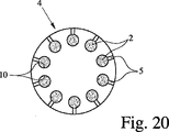
図20は、多数の貯蔵キャビティ10を備えた貯蔵装置4の別の実施形態を図19のディスペンサ1内に使用できる円形又は円板状構成で示している。
FIG. 20 shows another embodiment of the
貯蔵装置4は、図20に示すように半径方向に差し向けることができるダクト5を有している。この構成は、各投与分の粉末2を別個の、即ち、未使用状態のダクト5中へ小出しできるという利点を備えている。所望ならば、破裂要素12を図20に示すように各貯蔵チャンバ10とそれぞれのダクト5との間に配置するのがよい。さらに、混合チャンバ14を所望ならば特に破裂要素12とダクト5の間で各貯蔵チャンバ10に関連付けるのがよい。変形例として、各貯蔵チャンバ10は又、図10の実施形態と関連して上述したように混合チャンバを形成してもよい。他の実施形態の特徴、例えば、粉末ジェット衝突手段18等も又、図20の実施形態で実現できることが指摘される。
The
ガスを貯蔵キャビティ10内へ、例えば、それぞれのガス供給要素29等を挿入することにより特に軸方向又は接線方向に供給するのがよい。
The gas may be supplied into the
注目されなければならないこととして、本発明、具体的には、ディスペンサ1及び(又は)貯蔵装置4を1種類の薬剤、薬剤の配合物又は少なくとも2種類又は3種類の別々の薬剤を小出しするのに使用できる。後者の場合、別々の薬剤は、別々の貯蔵チャンバ10内に貯蔵され、小出し操作の際、これら薬剤は、共通の混合チャンバ14内か別々の混合チャンバ14内かガスの入ったこれらのそれぞれの貯蔵チャンバ10内かのいずれかで混合させる。さらに、別々の薬剤を共通ダクト5又はノズル6若しくは別々のダクト5又はノズル6中へ放出するのがよい。後者の場合、別々の薬剤は、別々のダクト5/ノズル6を出た後、又はマウスピース31内で若しくは任意他の適当な(追加の)混合チャンバ内で混合されることになろう。また、別々の薬剤の粉末ジェットを衝突させることにより別々の薬剤を混合することが可能である。別々の薬剤を小出しするため、共通のガス供給源又はガスを加圧する手段、例えば空気ポンプ7若しくは別々のガス供給源/加圧ガスを提供する手段を用いることが可能である。
It should be noted that the present invention, in particular the
図21は、少なくとも2種類又は3種類の別々の粉末2、即ち、別々の薬剤の入ったディスペンサ1/貯蔵装置4の別の実施形態を示しており、これら粉末2は、別々の貯蔵チャンバ10′,10″,10′″内に貯蔵され、これら貯蔵チャンバは、中間壁32によって形成されるのがよく、各貯蔵チャンバをオプションとしての破裂要素12′,12″又は12′″によって覆うのがよい。加圧ガスを提供する共通の手段、特に、空気ポンプ7及び(又は)調整若しくは制御手段9から別々のガス入口11′,11″,11′″を介して加圧ガスを供給するのがよい。変形例として、別々のガス供給源を設けてもよい。
FIG. 21 shows another embodiment of the
ガス圧力が貯蔵チャンバ10′,10″,10′″内でピーク又は破裂圧力に達すると、それぞれの破裂要素12′,12″,12′″が破裂し、別々の薬剤/粉末2′,2″,2′″が、共通混合チャンバ14内で混ざり合うことができ、混合物は、一緒になってスプレー3(図示せず)として少なくとも1つの共通ダクト5、ノズル6等を通って小出しされる。
When the gas pressure reaches a peak or burst pressure within the
注目されなければならないこととして、破裂要素12′,12″,12′″を1つの共通材料層、特に、箔等で形成するのがよい。
It should be noted that the
変形例として、中央貯蔵チャンバ10″を少なくとも1つの好ましくは環状の貯蔵チャンバで包囲してもよい。この場合、壁32は、円筒形であるのがよく、参照符号10′,10′″は、同一の環状貯蔵チャンバを示しており、その結果、図21の実施形態では、2種類の互いに異なる薬剤/粉末2だけが、2つの別々の貯蔵チャンバ(中央チャンバ及び環状チャンバ)内に入れられる。この場合、参照符号12′,12′″は、環状チャンバを覆う同一の環状破裂要素を示している。
As a variant, the
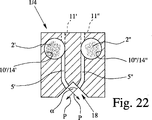
図22は、ディスペンサ1及び貯蔵装置4の別の実施形態を概略断面図で示している。2種類の互いに異なる薬剤/粉末2′,2″が、それぞれ、別々の貯蔵/混合チャンバ10′/14′及び10″/14″内に入れられている。ガスを別々のガス入口11′,11″を介してチャンバ11′/14′,10″/14″に供給するのがよい。粉末2′,2″を別々のダクト5′,5″又は別々のノズル(図示せず)等により小出しして解凝集するのがよい。別々のダクト5′,5″から噴出した別々の又は互いに異なる薬剤/粉末2′,2″の粉末ジェットPを好ましくは、互いに衝突させて別々の薬剤/粉末2′,2″をちょうどスプレー3(図示せず)を形成したときに混合する。粉末ジェット衝突手段18は、別々の薬剤/粉末2′,2″を混合するが、スプレー3の伝搬速度を減速させると共に(或いは)粉末2′,2″の解凝集を支援し或いはそれぞれの薬剤をキャリヤから分離するのにも役立ちうる。
FIG. 22 shows another embodiment of the
以下において、本発明の作用効果を示す2つの実施例を説明する。
実施例1:90.0重量%の乳糖200、9.7重量%の高純度乳糖及び0.3重量%のチオトロピウム(Tiotropium)の配合物を使用した。乳糖200の平均粒子直径は、約45μm、高純度乳糖の平均粒子直径は、約4μm、チオトロピウムの平均粒子直径は、約4μmであった。約5.5mgの配合物を粉末2として貯蔵及び混合チャンバ10/14内に配置し、この貯蔵及び混合チャンバ10/14は、直径が3mm、軸方向長さは3mmの実質的に円筒形の形をしていた。5mlの圧縮空気をゲージ圧が約100kPaの状態で、0.5mmの入口オリフィスを備えたガス入口を介してチャンバ10/14内へ供給した。粉末2を最も短い辺が約0.18mm、最も長い辺が約1.5mmの実質的に矩形の断面のダクト5を介して小出しした。ダクト5は、2つのダクト区分5a,5b(特に、図13に示されている)に分かれており、各区分は、最も短い辺が約0.18mm、最も長い辺が約0.75mmの実質的に矩形の断面を有していた。区分5a,5bを含むダクト5の全長は、約8mmであった。その結果、チャンバ10/14内の100%の計量された状態の塊、即ち、全ての粉末2を小出しした。直径平均微小フラクションと質量平均微小フラクションの両方のうち約50%を30l/分と60l/分の両方でアンダーソン・カスケード・インパクタ(Anderson Cascade Impactor)で測定した。
In the following, two embodiments showing the effects of the present invention will be described.
Example 1: A formulation of 90.0 wt% lactose 200, 9.7 wt% high purity lactose and 0.3 wt% Tiotropium was used. The average particle diameter of lactose 200 was about 45 μm, the average particle diameter of high-purity lactose was about 4 μm, and the average particle diameter of tiotropium was about 4 μm. About 5.5 mg of the formulation is placed as
実施例2:平均粒子直径が4μmのフェノテロール(Fenoterol)を約1.5mg、粉末2として貯蔵及び混合チャンバ10/14内に配置し、この貯蔵及び混合チャンバは、直径が2mm、軸方向長さが2mmの実質的に円筒形の形をしていた。5mlの圧縮空気をゲージ圧が約150kPaの状態で、0.5mmの入口オリフィスを備えたガス入口を介してチャンバ10/14内へ供給した。粉末2を最も短い辺が約0.075mm、最も長い辺が約1.5mmの実質的に矩形の断面のダクト5を介して小出しした。ダクト5は、2つのダクト区分5a,5b(特に、図13に示されている)に分かれており、各区分は、最も短い辺が約0.075mm、最も長い辺が約0.75mmの実質的に矩形の断面を有していた。区分5a,5bを含むダクト5の全長は、約8mmであった。その結果、チャンバ10/14内の100%の計量された状態の塊、即ち、全ての粉末2を小出しした。直径平均微小フラクションと質量平均微小フラクションの両方のうち約45%を30l/分と60l/分の両方でアンダーソン・カスケード・インパクタ(Anderson Cascade Impactor)で測定した。
Example 2: About 1.5 mg of Fenoterol with an average particle diameter of 4 μm, placed as a
Claims (45)
前記ディスペンサ(1)は、前記粉末(2)を解凝集し、或いは、前記スプレー(3)の伝搬速度を減速させ、或いは、別々の粉末(2)を混合するように、少なくとも2つの粉末ジェット(P)を互いに衝突させる粉末ジェット衝突手段(18)を有することを特徴とする、ディスペンサ。Dispenser (1) for dispensing powder (2) as a spray (3) containing fine powder particles, the dispenser having a duct (5) so that the powder (2) can be deagglomerated, In a dispenser wherein the powder (2) can be dispensed through the duct by gas pressure;
The dispenser (1) is configured to deagglomerate the powder (2), reduce the propagation speed of the spray (3), or mix at least two powder jets (2). Dispenser characterized by having powder jet impinging means (18) for colliding (P) with each other.
前記ディスペンサ(1)は、投与一回分の前記粉末(2)を収容した少なくとも1つの貯蔵チャンバ(10)を備えた貯蔵装置(4)を受け入れ、又は、この貯蔵装置を有するようになっており、
前記ディスペンサ(1)は、ダクト(5)又はノズル(6)を通って前記粉末(2)を小出しする加圧ガスを提供する手段を有するディスペンサにおいて、
前記貯蔵チャンバ(10)は、破裂要素(12)又は別の感圧要素によって閉鎖されており、前記破裂要素又は感圧要素は、前記加圧ガスが前記破裂要素(12)を破裂させ又は前記感圧要素を開いて前記粉末(2)を前記関連の貯蔵チャンバ(10)から放出して前記粉末(2)を小出しすることができるよう設計されており、或いは、
前記貯蔵チャンバ(10)へのガス供給源又は入口(11)の第1の断面は、前記粉末(2)のための出口の第2の断面よりも小さく、それにより、前記第1の断面による前記粉末(2)の小出し中、前記ガスの流れを実質的に制御し又は制限するように構成されている、
ことを特徴とするディスペンサ。Dispenser (1) according to any one of the preceding claims, characterized in that the powder (2) is dispensed as a spray (3) containing fine powder particles,
The dispenser (1) accepts or has a storage device (4) comprising at least one storage chamber (10) containing a dose of the powder (2). ,
The dispenser (1) comprises a means for providing a pressurized gas for dispensing the powder (2) through a duct (5) or a nozzle (6),
The storage chamber (10) is closed by a rupture element (12) or another pressure sensitive element, the rupture element or pressure sensitive element causing the pressurized gas to rupture the rupture element (12) or Designed to open a pressure sensitive element and release the powder (2) from the associated storage chamber (10) to dispense the powder (2), or
The first cross section of the gas supply source or inlet (11) to the storage chamber (10) is smaller than the second cross section of the outlet for the powder (2), thereby according to the first cross section. Configured to substantially control or limit the flow of the gas during dispensing of the powder (2);
A dispenser characterized by that.
前記少なくとも1つの貯蔵チャンバ(10)は、破裂要素(12)によって閉鎖されており、前記破裂要素は、前記粉末(2)を関連の前記貯蔵チャンバ(10)から放出して前記粉末(2)を小出しするために前記破裂要素(12)を破裂させることができるように設計され、
或いは、
前記貯蔵装置(4)は、ダクト(5)、又は、ノズル(6)を有し、前記ダクト、又は、前記ノズルは、各投与分の前記粉末(2)を前記ガス圧力により別々のダクト(5)又はノズル(6)から小出しできるように前記貯蔵チャンバ(10)に連係するように設計される、
ことを特徴とする、請求項9から20のいずれか1項に記載のディスペンサ。Said storage device (4) has at least one storage chamber (10) containing a dose of powder (2) each to be dispensed by gas pressure;
Said at least one storage chamber (10) is closed by a rupture element (12), said rupture element discharging said powder (2) from said associated storage chamber (10) and said powder (2). Designed to be able to rupture the rupture element (12) to dispense
Or
The storage device (4) has a duct (5) or a nozzle (6), which separates the powder (2) for each dose by means of the gas pressure. 5) or designed to be linked to the storage chamber (10) so that it can be dispensed from the nozzle (6);
21. A dispenser according to any one of claims 9 to 20, characterized in that
前記貯蔵装置(1)は、前記粉末(2)を解凝集し、或いは、前記スプレー(3)の伝搬速度を減速させ、或いは、別々の粉末(2)を混合するように、少なくとも2つの粉末ジェット(P)を互いに衝突させる粉末ジェット衝突手段(18)を有することを特徴とする、貯蔵装置。A storage device (4) for powder (2), comprising a number of separate storage chambers (10) each containing a dose of said powder (2) to be dispensed by gas pressure,
The storage device (1) deagglomerates the powder (2), reduces the propagation speed of the spray (3), or mixes the separate powders (2). Storage device, characterized by having powder jet impinging means (18) for impinging the jets (P) on each other.
Applications Claiming Priority (9)
| Application Number | Priority Date | Filing Date | Title |
|---|---|---|---|
| GB0422106.5 | 2004-10-06 | ||
| GB0422106A GB0422106D0 (en) | 2004-10-06 | 2004-10-06 | Powder dispensing means |
| GB0425289A GB0425289D0 (en) | 2004-11-17 | 2004-11-17 | Powder dispensing means |
| GB0425289.6 | 2004-11-17 | ||
| GB0427552A GB0427552D0 (en) | 2004-12-15 | 2004-12-15 | Powder dispensing means |
| GB0427552.5 | 2004-12-15 | ||
| GB0509108A GB0509108D0 (en) | 2005-05-04 | 2005-05-04 | Powder dispensing means |
| GB0509108.7 | 2005-05-04 | ||
| PCT/EP2005/010768 WO2006037636A2 (en) | 2004-10-06 | 2005-10-06 | Dispensing device, storage device and method for dispensing powder |
Publications (3)
| Publication Number | Publication Date |
|---|---|
| JP2008515499A JP2008515499A (en) | 2008-05-15 |
| JP2008515499A5 JP2008515499A5 (en) | 2008-11-20 |
| JP4908419B2 true JP4908419B2 (en) | 2012-04-04 |
Family
ID=35457812
Family Applications (1)
| Application Number | Title | Priority Date | Filing Date |
|---|---|---|---|
| JP2007535090A Active JP4908419B2 (en) | 2004-10-06 | 2005-10-06 | Dispenser, storage device and powder dispensing method |
Country Status (12)
| Country | Link |
|---|---|
| US (2) | US9283335B2 (en) |
| EP (2) | EP1819388A2 (en) |
| JP (1) | JP4908419B2 (en) |
| KR (1) | KR20070073865A (en) |
| CN (1) | CN101785892B (en) |
| AU (1) | AU2005291427A1 (en) |
| CA (1) | CA2581044C (en) |
| EA (1) | EA200700743A1 (en) |
| IL (1) | IL182402A0 (en) |
| MX (1) | MX2007004106A (en) |
| NO (1) | NO20071541L (en) |
| WO (1) | WO2006037636A2 (en) |
Families Citing this family (116)
| Publication number | Priority date | Publication date | Assignee | Title |
|---|---|---|---|---|
| US9006175B2 (en) | 1999-06-29 | 2015-04-14 | Mannkind Corporation | Potentiation of glucose elimination |
| GB0128148D0 (en) * | 2001-11-23 | 2002-01-16 | Innovata Biomed Ltd | Assembly |
| WO2003080149A2 (en) | 2002-03-20 | 2003-10-02 | Mannkind Corporation | Inhalation apparatus |
| US7638138B2 (en) * | 2003-02-21 | 2009-12-29 | Translational Research, Ltd. | Compositions for nasal administration of pharmaceuticals |
| KR100974482B1 (en) | 2003-03-27 | 2010-08-10 | 가부시키가이샤 바이오악티스 | Powder medicine applicator for nasal cavity |
| WO2006016530A1 (en) * | 2004-08-10 | 2006-02-16 | Translational Research, Ltd. | Transnasal composition having immediate action and high absorbability |
| JP5078014B2 (en) | 2004-08-20 | 2012-11-21 | マンカインド コーポレイション | Catalytic reaction of diketopiperazine synthesis. |
| MX2007002189A (en) | 2004-08-23 | 2008-01-11 | Mannkind Corp | Diketopiperazine salts, diketomorpholine salts or diketodioxane salts for drug delivery. |
| US7803404B2 (en) | 2005-09-14 | 2010-09-28 | Mannkind Corporation | Method of drug formulation based on increasing the affinity of active agents for crystalline microparticle surfaces |
| EP1795221A1 (en) * | 2005-12-02 | 2007-06-13 | Boehringer Ingelheim Pharma GmbH & Co. KG | Dispensing device, storage device and method for dispensing a formulation |
| IN2015DN00888A (en) | 2006-02-22 | 2015-07-10 | Mannkind Corp | |
| EP2004258A1 (en) * | 2006-04-13 | 2008-12-24 | Boehringer Ingelheim Microparts Gmbh | Dispensing device |
| DE102006043637A1 (en) | 2006-05-18 | 2007-11-22 | Boehringer Ingelheim Pharma Gmbh & Co. Kg | atomizer |
| EP1867357A1 (en) * | 2006-06-13 | 2007-12-19 | TrendTech A/S | Inhaler |
| JP2008049127A (en) * | 2006-07-24 | 2008-03-06 | Canon Inc | Inhaler |
| DE102006047667B3 (en) * | 2006-09-28 | 2008-04-24 | Ing. Erich Pfeiffer Gmbh | inhalator |
| US8337817B2 (en) | 2006-12-26 | 2012-12-25 | Shin Nippon Biomedical Laboratories, Ltd. | Preparation for transnasal application |
| EP1992372A1 (en) * | 2007-05-16 | 2008-11-19 | Boehringer Ingelheim Pharma GmbH & Co. KG | Dispensing device |
| EP1992378A1 (en) * | 2007-05-16 | 2008-11-19 | Boehringer Ingelheim Pharma GmbH & Co. KG | Dispensing device |
| EP1992374A1 (en) * | 2007-05-16 | 2008-11-19 | Boehringer Ingelheim Pharma GmbH & Co. KG | Dispensing device |
| EP1992381A1 (en) * | 2007-05-16 | 2008-11-19 | Boehringer Ingelheim Pharma GmbH & Co. KG | Dispensing device |
| EP1992376A1 (en) | 2007-05-16 | 2008-11-19 | Boehringer Ingelheim Pharma GmbH & Co. KG | Dispensing device |
| EP1992375A1 (en) * | 2007-05-16 | 2008-11-19 | Boehringer Ingelheim Pharma GmbH & Co. KG | Dispensing device |
| EP1992373A1 (en) * | 2007-05-16 | 2008-11-19 | Boehringer Ingelheim Pharma GmbH & Co. KG | Dispensing device |
| EP1992379A1 (en) | 2007-05-16 | 2008-11-19 | Boehringer Ingelheim Pharma GmbH & Co. KG | Dispensing device |
| EP1992377A1 (en) | 2007-05-16 | 2008-11-19 | Boehringer Ingelheim Pharma GmbH & Co. KG | Dispensing device |
| EP1992380A1 (en) * | 2007-05-16 | 2008-11-19 | Boehringer Ingelheim Pharma GmbH & Co. KG | Dispensing device |
| US8528544B2 (en) * | 2007-05-30 | 2013-09-10 | Canon Kabushiki Kaisha | Inhaler |
| WO2008145348A2 (en) | 2007-06-01 | 2008-12-04 | Boehringer Ingelheim International Gmbh | Dispensing device |
| EP2042208A1 (en) | 2007-09-25 | 2009-04-01 | Boehringer Ingelheim Pharma GmbH & Co. KG | Dispensing device |
| US8545457B2 (en) * | 2007-11-08 | 2013-10-01 | Terumo Kabushiki Kaisha | Sprayer |
| ES2394589T3 (en) | 2007-12-14 | 2013-02-04 | Aerodesigns, Inc | Supply of food products transformable in aerosol |
| EP2077132A1 (en) * | 2008-01-02 | 2009-07-08 | Boehringer Ingelheim Pharma GmbH & Co. KG | Dispensing device, storage device and method for dispensing a formulation |
| KR101933816B1 (en) | 2008-06-13 | 2019-03-29 | 맨카인드 코포레이션 | A dry powder inhaler and system for drug delivery |
| US8485180B2 (en) | 2008-06-13 | 2013-07-16 | Mannkind Corporation | Dry powder drug delivery system |
| WO2009155581A1 (en) | 2008-06-20 | 2009-12-23 | Mannkind Corporation | An interactive apparatus and method for real-time profiling of inhalation efforts |
| ITMI20081315A1 (en) * | 2008-07-18 | 2010-01-19 | Iph Establishment | DEVICE FOR REMOVING PULMONARY SECRECTIONS |
| TWI494123B (en) | 2008-08-11 | 2015-08-01 | Mannkind Corp | Use of ultrarapid acting insulin |
| US8314106B2 (en) | 2008-12-29 | 2012-11-20 | Mannkind Corporation | Substituted diketopiperazine analogs for use as drug delivery agents |
| PL2405963T3 (en) | 2009-03-11 | 2014-04-30 | Mannkind Corp | Apparatus, system and method for measuring resistance of an inhaler |
| JP2012520701A (en) | 2009-03-17 | 2012-09-10 | ベーリンガー インゲルハイム インターナショナル ゲゼルシャフト ミット ベシュレンクテル ハフツング | Dispensing device, storage device, and method of dispensing dispensed medicine |
| JP5670421B2 (en) | 2009-03-31 | 2015-02-18 | ベーリンガー インゲルハイム インターナショナル ゲゼルシャフト ミット ベシュレンクテル ハフツング | Component surface coating method |
| US9101539B2 (en) * | 2009-05-15 | 2015-08-11 | Shin Nippon Biomedical Laboratories, Ltd. | Intranasal pharmaceutical compositions with improved pharmacokinetics |
| JP5763053B2 (en) | 2009-05-18 | 2015-08-12 | ベーリンガー インゲルハイム インターナショナル ゲゼルシャフト ミット ベシュレンクテル ハフツング | Adapter, inhaler and atomizer |
| BRPI1013154B1 (en) | 2009-06-12 | 2020-04-07 | Mannkind Corp | MICROPARTICLES OF DICETOPIPERAZINE WITH SPECIFIC SURFACE AREAS DEFINED, DRY POWDER UNDERSTANDING THE REFERRED MICROPARTICLES, METHOD FOR FORMATION OF THE REFERENCESMICROPARTICLES AND THE FORMATION OF MICROPARTYSTEMS |
| WO2011008662A1 (en) * | 2009-07-13 | 2011-01-20 | Meadwestvaco Calmar Gmbh | Powder delivery devices and methods of using the same |
| GB2472327B (en) * | 2009-07-31 | 2013-03-13 | Shin Nippon Biomedical Lab Ltd | Intranasal granisetron and nasal applicator |
| CA2778698A1 (en) | 2009-11-03 | 2011-05-12 | Mannkind Corporation | An apparatus and method for simulating inhalation efforts |
| CA2779011C (en) * | 2009-11-13 | 2017-12-05 | Schering Corporation | Drug products, dry powder inhalers and polyflux collider arrangements |
| WO2011064163A1 (en) | 2009-11-25 | 2011-06-03 | Boehringer Ingelheim International Gmbh | Nebulizer |
| US10016568B2 (en) | 2009-11-25 | 2018-07-10 | Boehringer Ingelheim International Gmbh | Nebulizer |
| JP5715640B2 (en) | 2009-11-25 | 2015-05-13 | ベーリンガー インゲルハイム インターナショナル ゲゼルシャフト ミット ベシュレンクテル ハフツング | Nebulizer |
| DK2515977T3 (en) | 2009-12-26 | 2018-04-16 | Inspiro Medical Ltd | DEVICE FOR DELIVERY OF DRY POWDER |
| MX2012014463A (en) * | 2010-06-16 | 2013-02-11 | Nestec Sa | Beverage dispenser with improved powder dosing system. |
| MX359281B (en) | 2010-06-21 | 2018-09-21 | Mannkind Corp | Dry powder drug delivery system and methods. |
| US9943654B2 (en) | 2010-06-24 | 2018-04-17 | Boehringer Ingelheim International Gmbh | Nebulizer |
| RU2612506C2 (en) | 2011-03-03 | 2017-03-09 | Импел Ньюрофарма Инк. | Nasal drug delivery device |
| MX353285B (en) | 2011-04-01 | 2018-01-05 | Mannkind Corp | Blister package for pharmaceutical cartridges. |
| WO2012130757A1 (en) | 2011-04-01 | 2012-10-04 | Boehringer Ingelheim International Gmbh | Medical device comprising a container |
| CA2835208C (en) * | 2011-05-09 | 2019-08-20 | Impel Neuropharma, Inc. | Nozzles for nasal drug delivery |
| US9827384B2 (en) | 2011-05-23 | 2017-11-28 | Boehringer Ingelheim International Gmbh | Nebulizer |
| WO2012174472A1 (en) | 2011-06-17 | 2012-12-20 | Mannkind Corporation | High capacity diketopiperazine microparticles |
| IN2014DN03093A (en) | 2011-10-24 | 2015-05-15 | Mannkind Corp | |
| BR112014014594B1 (en) * | 2011-12-16 | 2021-02-17 | Indosys Limited | dry powder medicine delivery device |
| US10682476B2 (en) * | 2012-02-21 | 2020-06-16 | Respira Therapeutics, Inc. | Powder inhaler, system and methods |
| US10463815B2 (en) | 2012-02-21 | 2019-11-05 | Respira Therapeutics, Inc. | Inhaler to deliver substances for prophylaxis or prevention of disease or injury caused by the inhalation of biological or chemical agents |
| WO2013152894A1 (en) | 2012-04-13 | 2013-10-17 | Boehringer Ingelheim International Gmbh | Atomiser with coding means |
| SG10201605800UA (en) | 2012-07-12 | 2016-09-29 | Mannkind Corp | Dry powder drug delivery system and methods |
| KR101313993B1 (en) * | 2012-07-24 | 2013-10-01 | 한국화학연구원 | Nebulizer |
| KR101373981B1 (en) * | 2012-07-24 | 2014-03-12 | 한국화학연구원 | Nebulizer |
| WO2014066856A1 (en) | 2012-10-26 | 2014-05-01 | Mannkind Corporation | Inhalable influenza vaccine compositions and methods |
| US8845578B2 (en) | 2013-02-28 | 2014-09-30 | Medtronic Xomed, Inc. | Biomaterial delivery device |
| US8920364B2 (en) | 2013-02-28 | 2014-12-30 | Medtronic Xomed, Inc. | Biomaterial delivery device |
| KR102499439B1 (en) | 2013-03-15 | 2023-02-13 | 맨카인드 코포레이션 | Microcrystalline diketopiperazine compositions and methods |
| US9867931B2 (en) | 2013-10-02 | 2018-01-16 | Cook Medical Technologies Llc | Therapeutic agents for delivery using a catheter and pressure source |
| CA2909954C (en) | 2013-04-28 | 2021-03-23 | Impel Neuropharma, Inc. | Medical unit dose container |
| CA2918369C (en) | 2013-07-18 | 2021-06-29 | Mannkind Corporation | Heat-stable dry powder pharmaceutical compositions and methods |
| WO2015021064A1 (en) | 2013-08-05 | 2015-02-12 | Mannkind Corporation | Insufflation apparatus and methods |
| WO2015018904A1 (en) | 2013-08-09 | 2015-02-12 | Boehringer Ingelheim International Gmbh | Nebulizer |
| EP2835146B1 (en) | 2013-08-09 | 2020-09-30 | Boehringer Ingelheim International GmbH | Nebulizer |
| WO2015062420A1 (en) * | 2013-10-28 | 2015-05-07 | 浙江三创生物科技有限公司 | Powder injection method and apparatus |
| GB2520958A (en) * | 2013-12-04 | 2015-06-10 | Team Consulting Ltd | An apparatus and method for providing aerosolized powder delivery |
| NO2709641T3 (en) | 2014-03-10 | 2018-05-12 | ||
| US10307464B2 (en) | 2014-03-28 | 2019-06-04 | Mannkind Corporation | Use of ultrarapid acting insulin |
| SE538399C2 (en) * | 2014-04-03 | 2016-06-14 | Iconovo Ab | Dry powder inhaler |
| JP6745225B2 (en) | 2014-05-07 | 2020-08-26 | ベーリンガー インゲルハイム インターナショナル ゲゼルシャフト ミット ベシュレンクテル ハフツング | Container, display device, and nebulizer |
| ES2874029T3 (en) | 2014-05-07 | 2021-11-04 | Boehringer Ingelheim Int | Nebulizer |
| PL3139979T3 (en) | 2014-05-07 | 2023-12-27 | Boehringer Ingelheim International Gmbh | Unit, nebulizer and method |
| JP6474062B2 (en) * | 2014-07-03 | 2019-02-27 | 株式会社エアーサーフ | Powder sprayer |
| WO2016014153A1 (en) * | 2014-07-23 | 2016-01-28 | Microdose Therapeutx, Inc. | Dry powder nebulizer |
| US10561806B2 (en) | 2014-10-02 | 2020-02-18 | Mannkind Corporation | Mouthpiece cover for an inhaler |
| WO2016115379A1 (en) * | 2015-01-14 | 2016-07-21 | Respira Therapeutics, Inc. | Powder dispersion methods and devices |
| CN105999486B (en) * | 2015-03-21 | 2018-11-09 | 深圳百美酶生物医药科技有限公司 | Manual Diskus and its application in lung cancer therapy |
| EP3294390B1 (en) * | 2015-05-08 | 2022-10-05 | Iconovo AB | Dry powder inhaler |
| US9981233B2 (en) * | 2015-07-24 | 2018-05-29 | Phillip Phung-I HO | Portable mixer and dispenser for multi-component substances |
| US10441761B2 (en) | 2016-07-01 | 2019-10-15 | Boston Scientific Scimed, Inc. | Delivery devices and methods |
| CN110382027B (en) | 2017-01-10 | 2022-10-14 | 波士顿科学国际有限公司 | Device and method for delivering a powdered medicament |
| CA3061175A1 (en) * | 2017-05-02 | 2018-11-08 | Csp Technologies, Inc. | Mineral entrained plastic formulations as puncturing elements |
| WO2018234524A1 (en) * | 2017-06-22 | 2018-12-27 | Softhale Nv | Multiliquid-nozzle |
| US11744967B2 (en) | 2017-09-26 | 2023-09-05 | Shin Nippon Biomedical Laboratories, Ltd. | Intranasal delivery devices |
| CN108261604A (en) * | 2017-12-07 | 2018-07-10 | 上海昊海生物科技股份有限公司 | The aseptic powdery spray equipment closed for wound care, the surface of a wound |
| GB201721477D0 (en) | 2017-12-20 | 2018-01-31 | British American Tobacco Investments Ltd | Electronic aerosol provision system |
| GB201721470D0 (en) | 2017-12-20 | 2018-01-31 | British American Tobacco Investments Ltd | Electronic aerosol provision system |
| GB201721447D0 (en) * | 2017-12-20 | 2018-01-31 | British American Tobacco Investments Ltd | Electronic aerosol provision system |
| KR20200108020A (en) | 2018-01-12 | 2020-09-16 | 보스톤 싸이엔티픽 싸이메드 인코포레이티드 | Powder to achieve hemostasis |
| US11766546B2 (en) | 2018-01-31 | 2023-09-26 | Boston Scientific Scimed, Inc. | Apparatuses and methods for delivering powdered agents |
| FI129554B (en) | 2018-02-15 | 2022-04-14 | Danstar Ferment Ag | A spreading device and a powder cartridge available therein as well as a powder-like mixture contained in a powder cartridge |
| CN109259413B (en) * | 2018-08-02 | 2021-05-14 | 合肥中科力一科技有限公司 | Beauty skin care spraying instrument and system thereof |
| AU2019352968A1 (en) | 2018-10-02 | 2021-04-01 | Boston Scientific Scimed, Inc. | Devices for fluidization and delivering a powdered agent |
| JP7442512B2 (en) | 2018-10-02 | 2024-03-04 | ボストン サイエンティフィック サイムド,インコーポレイテッド | Equipment for fluidization and delivery of powders |
| CN110040370B (en) * | 2019-05-20 | 2023-07-07 | 核工业理化工程研究院 | Hand-held radioactive pollution decontaminating device |
| EP4309564A3 (en) | 2019-12-03 | 2024-04-17 | Boston Scientific Scimed, Inc. | Medical devices for agent delivery |
| EP4017377A1 (en) | 2019-12-03 | 2022-06-29 | Boston Scientific Scimed, Inc. | Agent administering medical device |
| KR102408182B1 (en) * | 2020-02-17 | 2022-06-13 | 주식회사 케이티앤지 | Aerosol inhaler and capsule for the aerosol inhaler |
| WO2022049136A1 (en) * | 2020-09-01 | 2022-03-10 | Janssen Pharmaceutica Nv | Drug delivery systems and methods and drug products |
| US20220266282A1 (en) * | 2021-02-24 | 2022-08-25 | Glorymakeup Inc. | Multi-nozzle spray disk for automatic makeup machine |
Citations (2)
| Publication number | Priority date | Publication date | Assignee | Title |
|---|---|---|---|---|
| GB2323042A (en) * | 1997-03-12 | 1998-09-16 | David Reginald Theobald | Dry powder nebuliser |
| GB2375308A (en) * | 2001-05-10 | 2002-11-13 | Cambridge Consultants | Inhalers |
Family Cites Families (36)
| Publication number | Priority date | Publication date | Assignee | Title |
|---|---|---|---|---|
| GB8311167D0 (en) * | 1983-04-25 | 1983-06-02 | Jenkins W N | Directed spray |
| US5239991A (en) * | 1989-06-21 | 1993-08-31 | Fisons Plc | Disposable powder medicament inhalation device with peel-off cover |
| GB9004781D0 (en) | 1990-03-02 | 1990-04-25 | Glaxo Group Ltd | Device |
| SG45171A1 (en) * | 1990-03-21 | 1998-01-16 | Boehringer Ingelheim Int | Atomising devices and methods |
| GB9021433D0 (en) * | 1990-10-02 | 1990-11-14 | Atomic Energy Authority Uk | Power inhaler |
| GB9100950D0 (en) | 1991-01-16 | 1991-02-27 | Dunne Miller Weston Ltd | Metered dose atomising and delivery device |
| DK198591D0 (en) * | 1991-12-10 | 1991-12-10 | Novo Nordisk As | APPARATUS |
| US5785049A (en) * | 1994-09-21 | 1998-07-28 | Inhale Therapeutic Systems | Method and apparatus for dispersion of dry powder medicaments |
| US6007676A (en) * | 1992-09-29 | 1999-12-28 | Boehringer Ingelheim International Gmbh | Atomizing nozzle and filter and spray generating device |
| IL107120A (en) * | 1992-09-29 | 1997-09-30 | Boehringer Ingelheim Int | Atomising nozzle and filter and spray generating device |
| US5497763A (en) | 1993-05-21 | 1996-03-12 | Aradigm Corporation | Disposable package for intrapulmonary delivery of aerosolized formulations |
| CA2200727C (en) * | 1994-09-21 | 2006-11-28 | Adrian E. Smith | Apparatus and methods for dispersing dry powder medicaments |
| US5622166A (en) | 1995-04-24 | 1997-04-22 | Dura Pharmaceuticals, Inc. | Dry powder inhaler delivery system |
| US5921237A (en) | 1995-04-24 | 1999-07-13 | Dura Pharmaceuticals, Inc. | Dry powder inhaler |
| DE19518810A1 (en) | 1995-05-26 | 1996-11-28 | Bayer Ag | Nasal applicator |
| JP3434396B2 (en) * | 1995-06-30 | 2003-08-04 | 株式会社日立ユニシアオートモティブ | Nasal administration device |
| US5988163A (en) | 1995-08-02 | 1999-11-23 | Innovative Devices | Dry powder medicament inhalator having an inhalation-activated flow diverting means for triggering delivery of delivery of medicament |
| US5875776A (en) * | 1996-04-09 | 1999-03-02 | Vivorx Pharmaceuticals, Inc. | Dry powder inhaler |
| US6123070A (en) * | 1996-06-07 | 2000-09-26 | Valois S.A. | Device for enhancing the emptying of an inhaler metering chamber |
| JP3530004B2 (en) * | 1998-02-06 | 2004-05-24 | 株式会社日立ユニシアオートモティブ | Inhalation type dispenser |
| GB2340758A (en) * | 1998-08-21 | 2000-03-01 | Bespak Plc | Drug dispensing system |
| JP3739955B2 (en) * | 1999-01-11 | 2006-01-25 | 株式会社日立製作所 | Inhaler |
| JP2000217917A (en) * | 1999-01-27 | 2000-08-08 | Unisia Jecs Corp | Inhaler type medicine administration tool |
| DE60045037D1 (en) * | 1999-10-12 | 2010-11-11 | Nat Inst Of Advanced Ind Scien | HRES AND DEVICE FOR PRODUCTION |
| US6948492B2 (en) | 2000-08-15 | 2005-09-27 | University Of Kentucky Research Foundation | Programmable multi-dose intranasal drug delivery device |
| US6799572B2 (en) * | 2000-12-22 | 2004-10-05 | Chrysalis Technologies Incorporated | Disposable aerosol generator system and methods for administering the aerosol |
| US6626173B2 (en) * | 2001-01-08 | 2003-09-30 | Iep Pharmaceutical Devices Inc. | Dry powder inhaler |
| US6722364B2 (en) | 2001-01-12 | 2004-04-20 | Becton, Dickinson And Company | Medicament inhalation delivery devices and methods for using the same |
| US6644309B2 (en) * | 2001-01-12 | 2003-11-11 | Becton, Dickinson And Company | Medicament respiratory delivery device and method |
| WO2002092154A1 (en) * | 2001-04-26 | 2002-11-21 | New England Pharmaceuticals, Inc. | Metered dose delivery device for liquid and powder agents |
| US6729327B2 (en) * | 2001-12-17 | 2004-05-04 | Joseph L. McFarland, Jr. | Portable, handheld, pneumatic driven medicinal nebulizer |
| EP1585561A2 (en) * | 2002-10-30 | 2005-10-19 | Glaxo Group Limited | Tubular nozzles for use in systems for delivering medicaments |
| DE10300983A1 (en) * | 2003-01-14 | 2004-07-22 | Boehringer Ingelheim Pharma Gmbh & Co. Kg | Jet system for an inhaler, to deliver a mist of fluid droplets, has inner surfaces with micro- or nano-structures on the surfaces in contact with the aerosol flow to reduce precipitation |
| KR100974482B1 (en) * | 2003-03-27 | 2010-08-10 | 가부시키가이샤 바이오악티스 | Powder medicine applicator for nasal cavity |
| JP2006522634A (en) * | 2003-04-14 | 2006-10-05 | ベクトゥラ・リミテッド | Device and pharmaceutical composition for improving administration efficiency |
| DE102004012093A1 (en) * | 2004-03-05 | 2005-09-22 | Boehringer Ingelheim Pharma Gmbh & Co. Kg | Powder inhaler with Merkanaldüse |
-
2005
- 2005-10-06 JP JP2007535090A patent/JP4908419B2/en active Active
- 2005-10-06 EA EA200700743A patent/EA200700743A1/en unknown
- 2005-10-06 AU AU2005291427A patent/AU2005291427A1/en not_active Abandoned
- 2005-10-06 WO PCT/EP2005/010768 patent/WO2006037636A2/en active Application Filing
- 2005-10-06 KR KR1020077010109A patent/KR20070073865A/en not_active Application Discontinuation
- 2005-10-06 CA CA2581044A patent/CA2581044C/en not_active Expired - Fee Related
- 2005-10-06 MX MX2007004106A patent/MX2007004106A/en not_active Application Discontinuation
- 2005-10-06 EP EP05797355A patent/EP1819388A2/en not_active Withdrawn
- 2005-10-06 US US11/576,853 patent/US9283335B2/en active Active
- 2005-10-06 EP EP10010487.6A patent/EP2277577B1/en active Active
- 2005-10-06 CN CN201010104382.4A patent/CN101785892B/en active Active
-
2007
- 2007-03-23 NO NO20071541A patent/NO20071541L/en not_active Application Discontinuation
- 2007-04-10 IL IL182402A patent/IL182402A0/en unknown
-
2012
- 2012-05-11 US US13/469,631 patent/US9089658B2/en active Active
Patent Citations (2)
| Publication number | Priority date | Publication date | Assignee | Title |
|---|---|---|---|---|
| GB2323042A (en) * | 1997-03-12 | 1998-09-16 | David Reginald Theobald | Dry powder nebuliser |
| GB2375308A (en) * | 2001-05-10 | 2002-11-13 | Cambridge Consultants | Inhalers |
Also Published As
| Publication number | Publication date |
|---|---|
| KR20070073865A (en) | 2007-07-10 |
| EP2277577A1 (en) | 2011-01-26 |
| CA2581044A1 (en) | 2006-04-13 |
| CN101785892A (en) | 2010-07-28 |
| NO20071541L (en) | 2007-05-04 |
| IL182402A0 (en) | 2007-07-24 |
| CN101785892B (en) | 2014-12-10 |
| US20070272763A1 (en) | 2007-11-29 |
| EP1819388A2 (en) | 2007-08-22 |
| JP2008515499A (en) | 2008-05-15 |
| US20120222675A1 (en) | 2012-09-06 |
| WO2006037636A3 (en) | 2006-07-20 |
| EA200700743A1 (en) | 2007-10-26 |
| US9089658B2 (en) | 2015-07-28 |
| MX2007004106A (en) | 2007-06-14 |
| US9283335B2 (en) | 2016-03-15 |
| WO2006037636A2 (en) | 2006-04-13 |
| CA2581044C (en) | 2013-09-03 |
| AU2005291427A1 (en) | 2006-04-13 |
| EP2277577B1 (en) | 2018-03-14 |
Similar Documents
| Publication | Publication Date | Title |
|---|---|---|
| JP4908419B2 (en) | Dispenser, storage device and powder dispensing method | |
| US10124129B2 (en) | Dispensing device, storage device and method for dispensing a formulation | |
| EP1351734B1 (en) | Dry powder inhaler | |
| EP1183060B1 (en) | Low spray force, low retention atomization system | |
| EP1328310B1 (en) | Dry powder inhaler | |
| EP1390091B1 (en) | Inhaler | |
| US20040211419A1 (en) | Inhalers | |
| JP2008515499A5 (en) | ||
| WO2007101557A2 (en) | Swirl | |
| AU2002232674A1 (en) | Dry powder inhaler | |
| JP7144455B2 (en) | Inhalation device and method with multi-liquid nozzle | |
| JP2009533104A (en) | Metering device | |
| CN101072599B (en) | Dispensing device, storage device | |
| WO2008017575A1 (en) | An inhaler and a method of dispensing medication to a person | |
| JP2020524542A (en) | Multi-liquid nozzle | |
| BRPI0516477B1 (en) | ADMINISTRATION DEVICE FOR POWDER ADMINISTRATION |
Legal Events
| Date | Code | Title | Description |
|---|---|---|---|
| A521 | Request for written amendment filed |
Free format text: JAPANESE INTERMEDIATE CODE: A523 Effective date: 20081001 |
|
| A621 | Written request for application examination |
Free format text: JAPANESE INTERMEDIATE CODE: A621 Effective date: 20081001 |
|
| A131 | Notification of reasons for refusal |
Free format text: JAPANESE INTERMEDIATE CODE: A131 Effective date: 20110117 |
|
| A521 | Request for written amendment filed |
Free format text: JAPANESE INTERMEDIATE CODE: A523 Effective date: 20110407 |
|
| A131 | Notification of reasons for refusal |
Free format text: JAPANESE INTERMEDIATE CODE: A131 Effective date: 20111011 |
|
| A521 | Request for written amendment filed |
Free format text: JAPANESE INTERMEDIATE CODE: A523 Effective date: 20111122 |
|
| TRDD | Decision of grant or rejection written | ||
| A01 | Written decision to grant a patent or to grant a registration (utility model) |
Free format text: JAPANESE INTERMEDIATE CODE: A01 Effective date: 20111219 |
|
| A01 | Written decision to grant a patent or to grant a registration (utility model) |
Free format text: JAPANESE INTERMEDIATE CODE: A01 |
|
| A61 | First payment of annual fees (during grant procedure) |
Free format text: JAPANESE INTERMEDIATE CODE: A61 Effective date: 20120112 |
|
| FPAY | Renewal fee payment (event date is renewal date of database) |
Free format text: PAYMENT UNTIL: 20150120 Year of fee payment: 3 |
|
| R150 | Certificate of patent or registration of utility model |
Ref document number: 4908419 Country of ref document: JP Free format text: JAPANESE INTERMEDIATE CODE: R150 Free format text: JAPANESE INTERMEDIATE CODE: R150 |
|
| R250 | Receipt of annual fees |
Free format text: JAPANESE INTERMEDIATE CODE: R250 |
|
| R250 | Receipt of annual fees |
Free format text: JAPANESE INTERMEDIATE CODE: R250 |
|
| R250 | Receipt of annual fees |
Free format text: JAPANESE INTERMEDIATE CODE: R250 |
|
| R250 | Receipt of annual fees |
Free format text: JAPANESE INTERMEDIATE CODE: R250 |
|
| R250 | Receipt of annual fees |
Free format text: JAPANESE INTERMEDIATE CODE: R250 |
|
| R250 | Receipt of annual fees |
Free format text: JAPANESE INTERMEDIATE CODE: R250 |
|
| R250 | Receipt of annual fees |
Free format text: JAPANESE INTERMEDIATE CODE: R250 |
|
| R250 | Receipt of annual fees |
Free format text: JAPANESE INTERMEDIATE CODE: R250 |
|
| R250 | Receipt of annual fees |
Free format text: JAPANESE INTERMEDIATE CODE: R250 |
|
| R250 | Receipt of annual fees |
Free format text: JAPANESE INTERMEDIATE CODE: R250 |