EP2236227B1 - Forming tool with a rotatable base body - Google Patents
Forming tool with a rotatable base body Download PDFInfo
- Publication number
- EP2236227B1 EP2236227B1 EP10156343.5A EP10156343A EP2236227B1 EP 2236227 B1 EP2236227 B1 EP 2236227B1 EP 10156343 A EP10156343 A EP 10156343A EP 2236227 B1 EP2236227 B1 EP 2236227B1
- Authority
- EP
- European Patent Office
- Prior art keywords
- lever
- shaping tool
- tool according
- roller
- bending roller
- Prior art date
- Legal status (The legal status is an assumption and is not a legal conclusion. Google has not performed a legal analysis and makes no representation as to the accuracy of the status listed.)
- Active
Links
- 238000005452 bending Methods 0.000 claims abstract description 36
- 238000007493 shaping process Methods 0.000 claims abstract 12
- XAGFODPZIPBFFR-UHFFFAOYSA-N aluminium Chemical compound [Al] XAGFODPZIPBFFR-UHFFFAOYSA-N 0.000 claims description 17
- 229910052782 aluminium Inorganic materials 0.000 claims description 17
- 238000009472 formulation Methods 0.000 claims description 4
- 239000000203 mixture Substances 0.000 claims description 4
- 239000013543 active substance Substances 0.000 claims 1
- 239000004411 aluminium Substances 0.000 claims 1
- 230000002265 prevention Effects 0.000 claims 1
- 239000012530 fluid Substances 0.000 description 9
- 229940079593 drug Drugs 0.000 description 5
- 239000013583 drug formulation Substances 0.000 description 5
- 239000000443 aerosol Substances 0.000 description 4
- 238000004519 manufacturing process Methods 0.000 description 4
- 238000000034 method Methods 0.000 description 4
- 239000004480 active ingredient Substances 0.000 description 3
- 238000000889 atomisation Methods 0.000 description 2
- 239000011324 bead Substances 0.000 description 2
- 238000007906 compression Methods 0.000 description 2
- 230000006835 compression Effects 0.000 description 2
- 230000006378 damage Effects 0.000 description 2
- 238000006073 displacement reaction Methods 0.000 description 2
- 239000003814 drug Substances 0.000 description 2
- 239000007788 liquid Substances 0.000 description 2
- 239000002245 particle Substances 0.000 description 2
- 238000004544 sputter deposition Methods 0.000 description 2
- LERNTVKEWCAPOY-VOGVJGKGSA-N C[N+]1(C)[C@H]2C[C@H](C[C@@H]1[C@H]1O[C@@H]21)OC(=O)C(O)(c1cccs1)c1cccs1 Chemical compound C[N+]1(C)[C@H]2C[C@H](C[C@@H]1[C@H]1O[C@@H]21)OC(=O)C(O)(c1cccs1)c1cccs1 LERNTVKEWCAPOY-VOGVJGKGSA-N 0.000 description 1
- 230000008878 coupling Effects 0.000 description 1
- 238000010168 coupling process Methods 0.000 description 1
- 238000005859 coupling reaction Methods 0.000 description 1
- 230000000694 effects Effects 0.000 description 1
- 210000003746 feather Anatomy 0.000 description 1
- 238000005187 foaming Methods 0.000 description 1
- 238000009434 installation Methods 0.000 description 1
- 239000006199 nebulizer Substances 0.000 description 1
- 238000004806 packaging method and process Methods 0.000 description 1
- 230000002093 peripheral effect Effects 0.000 description 1
- 239000003380 propellant Substances 0.000 description 1
- 229960000257 tiotropium bromide Drugs 0.000 description 1
Images


Classifications
-
- B—PERFORMING OPERATIONS; TRANSPORTING
- B21—MECHANICAL METAL-WORKING WITHOUT ESSENTIALLY REMOVING MATERIAL; PUNCHING METAL
- B21D—WORKING OR PROCESSING OF SHEET METAL OR METAL TUBES, RODS OR PROFILES WITHOUT ESSENTIALLY REMOVING MATERIAL; PUNCHING METAL
- B21D51/00—Making hollow objects
- B21D51/16—Making hollow objects characterised by the use of the objects
- B21D51/26—Making hollow objects characterised by the use of the objects cans or tins; Closing same in a permanent manner
- B21D51/2615—Edge treatment of cans or tins
-
- B—PERFORMING OPERATIONS; TRANSPORTING
- B21—MECHANICAL METAL-WORKING WITHOUT ESSENTIALLY REMOVING MATERIAL; PUNCHING METAL
- B21D—WORKING OR PROCESSING OF SHEET METAL OR METAL TUBES, RODS OR PROFILES WITHOUT ESSENTIALLY REMOVING MATERIAL; PUNCHING METAL
- B21D15/00—Corrugating tubes
- B21D15/04—Corrugating tubes transversely, e.g. helically
- B21D15/06—Corrugating tubes transversely, e.g. helically annularly
-
- B—PERFORMING OPERATIONS; TRANSPORTING
- B21—MECHANICAL METAL-WORKING WITHOUT ESSENTIALLY REMOVING MATERIAL; PUNCHING METAL
- B21D—WORKING OR PROCESSING OF SHEET METAL OR METAL TUBES, RODS OR PROFILES WITHOUT ESSENTIALLY REMOVING MATERIAL; PUNCHING METAL
- B21D17/00—Forming single grooves in sheet metal or tubular or hollow articles
- B21D17/04—Forming single grooves in sheet metal or tubular or hollow articles by rolling
-
- B—PERFORMING OPERATIONS; TRANSPORTING
- B21—MECHANICAL METAL-WORKING WITHOUT ESSENTIALLY REMOVING MATERIAL; PUNCHING METAL
- B21D—WORKING OR PROCESSING OF SHEET METAL OR METAL TUBES, RODS OR PROFILES WITHOUT ESSENTIALLY REMOVING MATERIAL; PUNCHING METAL
- B21D39/00—Application of procedures in order to connect objects or parts, e.g. coating with sheet metal otherwise than by plating; Tube expanders
- B21D39/04—Application of procedures in order to connect objects or parts, e.g. coating with sheet metal otherwise than by plating; Tube expanders of tubes with tubes; of tubes with rods
-
- B—PERFORMING OPERATIONS; TRANSPORTING
- B21—MECHANICAL METAL-WORKING WITHOUT ESSENTIALLY REMOVING MATERIAL; PUNCHING METAL
- B21D—WORKING OR PROCESSING OF SHEET METAL OR METAL TUBES, RODS OR PROFILES WITHOUT ESSENTIALLY REMOVING MATERIAL; PUNCHING METAL
- B21D51/00—Making hollow objects
- B21D51/16—Making hollow objects characterised by the use of the objects
- B21D51/24—Making hollow objects characterised by the use of the objects high-pressure containers, e.g. boilers, bottles
-
- B—PERFORMING OPERATIONS; TRANSPORTING
- B21—MECHANICAL METAL-WORKING WITHOUT ESSENTIALLY REMOVING MATERIAL; PUNCHING METAL
- B21D—WORKING OR PROCESSING OF SHEET METAL OR METAL TUBES, RODS OR PROFILES WITHOUT ESSENTIALLY REMOVING MATERIAL; PUNCHING METAL
- B21D51/00—Making hollow objects
- B21D51/16—Making hollow objects characterised by the use of the objects
- B21D51/26—Making hollow objects characterised by the use of the objects cans or tins; Closing same in a permanent manner
- B21D51/2615—Edge treatment of cans or tins
- B21D51/263—Flanging
-
- B—PERFORMING OPERATIONS; TRANSPORTING
- B21—MECHANICAL METAL-WORKING WITHOUT ESSENTIALLY REMOVING MATERIAL; PUNCHING METAL
- B21D—WORKING OR PROCESSING OF SHEET METAL OR METAL TUBES, RODS OR PROFILES WITHOUT ESSENTIALLY REMOVING MATERIAL; PUNCHING METAL
- B21D51/00—Making hollow objects
- B21D51/16—Making hollow objects characterised by the use of the objects
- B21D51/26—Making hollow objects characterised by the use of the objects cans or tins; Closing same in a permanent manner
- B21D51/2615—Edge treatment of cans or tins
- B21D51/2638—Necking
-
- B—PERFORMING OPERATIONS; TRANSPORTING
- B21—MECHANICAL METAL-WORKING WITHOUT ESSENTIALLY REMOVING MATERIAL; PUNCHING METAL
- B21D—WORKING OR PROCESSING OF SHEET METAL OR METAL TUBES, RODS OR PROFILES WITHOUT ESSENTIALLY REMOVING MATERIAL; PUNCHING METAL
- B21D51/00—Making hollow objects
- B21D51/16—Making hollow objects characterised by the use of the objects
- B21D51/54—Making hollow objects characterised by the use of the objects cartridge cases, e.g. for ammunition, for letter carriers in pneumatic-tube plants
-
- A—HUMAN NECESSITIES
- A61—MEDICAL OR VETERINARY SCIENCE; HYGIENE
- A61M—DEVICES FOR INTRODUCING MEDIA INTO, OR ONTO, THE BODY; DEVICES FOR TRANSDUCING BODY MEDIA OR FOR TAKING MEDIA FROM THE BODY; DEVICES FOR PRODUCING OR ENDING SLEEP OR STUPOR
- A61M11/00—Sprayers or atomisers specially adapted for therapeutic purposes
-
- A—HUMAN NECESSITIES
- A61—MEDICAL OR VETERINARY SCIENCE; HYGIENE
- A61M—DEVICES FOR INTRODUCING MEDIA INTO, OR ONTO, THE BODY; DEVICES FOR TRANSDUCING BODY MEDIA OR FOR TAKING MEDIA FROM THE BODY; DEVICES FOR PRODUCING OR ENDING SLEEP OR STUPOR
- A61M15/00—Inhalators
- A61M15/009—Inhalators using medicine packages with incorporated spraying means, e.g. aerosol cans
-
- B—PERFORMING OPERATIONS; TRANSPORTING
- B05—SPRAYING OR ATOMISING IN GENERAL; APPLYING FLUENT MATERIALS TO SURFACES, IN GENERAL
- B05B—SPRAYING APPARATUS; ATOMISING APPARATUS; NOZZLES
- B05B11/00—Single-unit hand-held apparatus in which flow of contents is produced by the muscular force of the operator at the moment of use
- B05B11/01—Single-unit hand-held apparatus in which flow of contents is produced by the muscular force of the operator at the moment of use characterised by the means producing the flow
- B05B11/10—Pump arrangements for transferring the contents from the container to a pump chamber by a sucking effect and forcing the contents out through the dispensing nozzle
- B05B11/109—Pump arrangements for transferring the contents from the container to a pump chamber by a sucking effect and forcing the contents out through the dispensing nozzle the dispensing stroke being affected by the stored energy of a spring
- B05B11/1091—Pump arrangements for transferring the contents from the container to a pump chamber by a sucking effect and forcing the contents out through the dispensing nozzle the dispensing stroke being affected by the stored energy of a spring being first hold in a loaded state by locking means or the like, then released
Definitions
- the invention relates to a forming tool comprising a rotatable base body with at least one arranged on a circular path and rotatable about a rotation axis, profiled bending roller.
- inhalable pharmaceutical active ingredient formulations For the administration of inhalable pharmaceutical active ingredient formulations, hand-held and manually operated inhalers are used by the patient, in which the pharmaceutical active ingredient formulation is contained in each case in an inhaler cartridge.
- the inhaler cartridge consists of an outside aluminum cartridge and a plastic container inserted therein, which is a coextruded plastic container comprising a rigid outer container and a flexible inner bag disposed therein.
- an opening is introduced into the relatively stiff outer container, for example, with the so-called cut-crack-open process.
- the plastic container is filled with the pharmaceutical drug formulation and sealed and in Ways of the manufacturing process used to form the inhaler cartridge in the aluminum cartridge.
- a deformed wall portion is then formed in the upper part of the thus assembled inhaler cartridge in the aluminum cartridge, which bears against the outer surface of the plastic container inserted into the aluminum cartridge.
- a drawing method is used in which a rotating drawing tool moves with its tool opening from above over the connecting region of the aluminum cartridge and thereby brings profiled drawing rolls arranged around the tool working opening into contact with the lateral surface of the aluminum cartridge, to form the connection area by an axial movement.
- the aluminum cartridge is gas-tight in a further manufacturing step to the outside of the therein arranged plastic container, which is filled with a pharmaceutical drug formulation, applies.
- EP 0 916 428 in this context relates to a method and apparatus for forming an end portion of a sleeve.
- a roller is movably supported so that it can be moved radially toward and away from a main shaft. The method allows a tapered opening of a sleeve to be formed.
- the object is achieved by the forming tool according to claim 1.
- the forming tool As the forming tool rotates, the workpiece, the inhaler cartridge to be filled with a liquid drug formulation, can be fixed, thereby avoiding foaming of the drug formulation.
- the forming tool is positioned to the workpiece with the bending roller in the position defining the maximum tool working opening.
- the bending roller By means of a feed movement by means of the lever, the bending roller is displaced into the position defining the minimum tool working opening.
- the profiled bending roller is adapted to the contour to be produced and by the radial feed movement, for example, a circumferential radius is rotationally symmetrical to an upper edge of the course cylindrical workpiece, after an initially be made setting or determination of the diameter of the minimum tool opening a reliable, form and dimensionally accurate production can be achieved.
- the provision of the bending roller from the minimum tool working opening in the maximum tool working opening by means of a radially acting compression spring.
- the pressure piece In a further downward movement, the pressure piece is displaced downwards and the cone of the pressure piece acts on the lever to displace the bending roller in the radial direction in the position of the minimum tool working opening, in which the workpiece has its final contour.
- the pressure piece In the case of faulty axial positioning, the pressure piece would act on the lever too early or too late, which would result in a faulty, in particular non-gas-tight, final contour.
- the lever is provided on the pressure piece facing the end with a roll on the pressure roller and connected at its opposite end pivotally connected to the slider.
- a fixable eccentric bolt is inserted according to the invention into a bore of the slider and into a slot of the lever.
- the eccentric bolt is provided.
- the eccentric bolt is fixed, for example, by means of screws acting on it.
- the eccentric pin thus serves for the radial adjustment of the bending roller. If the radial position of the bending roller, for example, by a change in the diameter of the lever associated with the roller, which rolls on the pressure piece, is determined, it is not necessary to provide an eccentric pin.
- the lever is preferably mounted pivotably on a carrier part.
- the support member is positioned in the axial direction fixed to the slide and the pressure piece relative to the carrier part displaced.
- the lever has two articulated arms, between which acts a spring-loaded overload protection.
- the overload protection causes in a radial position of Beigerolle in which the finished dimension of the workpiece is achieved that the two arms of the lever pivot against the action of a spring to prevent further radial displacement of the bending roller and a concomitant damage to the workpiece.
- the spring-loaded overload protection it is also possible to generate a pressure required to ensure the deformation and a compensation of tolerances of the workpiece is possible.
- the spring of the overload protection can be effective both in an undersize of the workpiece as well as an oversize and always biases the bending roller against the workpiece.
- At least one forming roller for producing a bead is rotatably mounted on an axis of the slider in addition to the bending roller.
- the slider is slidably mounted by means of a tongue and groove guide in a guide member which is connected to the support member.
- a cam roller acts with a cam control for axial movement of the forming tool together.
- the traversing speeds and travel can be determined in a known manner.
- a holding device fixes the workpiece consisting of an aluminum cartridge and a plastic container coaxially to a longitudinal axis along which the forming tool moves vertically.
- the holding device may be part of a conveying and / or packaging installation, for example in the form of a rotary table machine or a conveyor belt.
- the above-described forming tool according to the invention is used for profiling a neck region of an inhaler cartridge, which consists of an outer-side aluminum cartridge and a plastic container inserted therein, which receives an active ingredient formulation.
- the plastic container can be produced by coextrusion and comprise a rigid outer container and a flexible inner bag arranged therein. The plastic container is filled in the course of production with the pharmaceutical drug formulation and sealed.
- the inhaler cartridge made with the forming tool is used as a reservoir in an atomizer for dispensing a certain amount of a fluid, in particular a drug, as an aerosol through a nozzle of one Used pressure accumulator, wherein a mechanical pressure generator applied to the measured fluid in the pressure accumulator, which must be released abruptly for sputtering.
- a fluid in particular a drug
- a known atomizer is offered under the trade name "Respimat" by the Boehringer Ingelheim KG in the form of an inhaler and is in the WO 91/14468 A1 as well as the WO 97/12687 A1 shown.
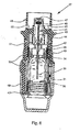
- the forming tool comprises a mounted in a hollow shaft 1 rod 2, which is connected to a rotary drive, not shown. Via a radially mounted tool-side cam roller 3, which cooperates with a cam control, an axial up and down movement of the forming tool is controlled.
- a housing 4 there are various bearing, coupling and spring elements.
- a pressure piece 5 is attached to a conical portion 6 and below the pressure piece 5 are a support member 7 and a guide member 8, wherein in the support member 7 three levers 9 are pivotally mounted, which cooperate at one end with the pressure piece 5
- Each of the slides 11 carries on a shaft 12 a bending roller 13 and a forming roller 14th
- the bending rollers 13 are movable from a position defining a maximum tool working opening into a position defining a minimal tool working opening.
- a hold-down device 15 initially presses on a workpiece 17, namely an inhaler cartridge 36, during a downward movement of the rotating forming tool according to the arrow 16.
- the levers 9 With a further downward movement, the levers 9 are pivoted according to the arrow 18 due to the action of the conical region 6 of the pressure element 5 and the pivotal movement of the lever 9 is converted into a radial advancing movement of the slider 11 according to the arrow 19 in order to move the bending roller 13 and the forming roller 14 into its end position in which they describe the minimum tool working opening.
- the levers 9 are pivoted by means of radially acting compression springs, which are supported on an intermediate ring 20, such that the bending roll 13 and the forming roll 14 are displaced into a position in which they reach the maximum tool working opening describe.
- the lever 9 comprises according to FIGS Fig. 1 . 4 and 5 two articulated arms 22, between which a spring-loaded overload protection 23 acts.
- the first arm 22 of the lever 9 has a slot 24 which projects through an eccentric pin 25 connected to the slider 11 in a fixable manner.
- a blind bore 26 for a radially acting return spring is embedded in this arm 22.
- the first arm 22 and the second arm 22 of the lever 9 are connected via a common pivot joint 27 with an engaging in the support member 7 pin 28 in connection.
- a spring 29 is arranged on a guide pin 30, that the second arm 22 against the first arm 22 of the lever 9 against the action of the spring 29 is pivotable about the bending roller 13 relative to the workpiece 17 bias and compensate for tolerances of the workpiece 17.
- the second arm 22 is opposite to the first arm 22 of the lever 9 against the effect the spring 29 pivotally when the bending roller 13 and the forming roller 14 have reached their end position and the pressure piece 5 exerts further force on the lever 9.
- a radius 33 is formed in the peripheral edge region of the workpiece 17, wherein the free edge of the aluminum cartridge 21 is formed such that it rests on the free end face of the plastic container.
- the forming rollers 14 essentially serve to form two circumferential groove-shaped beads 34 in a drawn neck region 35 of the workpiece 17.
- the inhaler cartridge 36 is used in an atomizer 37, which serves to atomize a fluid 39, in particular a highly effective drug, and is designed as a portable inhaler, which operates without propellant gas.
- a fluid 39 in particular a highly effective drug
- a portable inhaler which operates without propellant gas.
- an aerosol is formed, which can be inhaled by a user, not shown.
- the atomizer 37 has the inhaler cartridge 36 with the fluid 39, which can be inserted from below into the opened atomizer 37.
- the nebulizer 37 comprises a pressure generator 41 comprising a piston with a holder 42 for the inhaler cartridge 36, a drive spring 43 with a release button 44 which is manually operated for relaxation, a delivery tube 40 with a non-return valve 45 inserted , a pressure chamber 46 and a nozzle 47, which is associated with a mouthpiece 48.
- the atomization takes place, for example, in particles in the ⁇ m range, preferably in particles with a size of about 20 ⁇ m, which form a cloud or a jet of an aerosol.
- a user can inhale the aerosol, wherein supply air can be sucked via supply air openings 52 in the mouthpiece 48.
Landscapes
- Engineering & Computer Science (AREA)
- Mechanical Engineering (AREA)
- Containers And Packaging Bodies Having A Special Means To Remove Contents (AREA)
- Bending Of Plates, Rods, And Pipes (AREA)
- Shaping Metal By Deep-Drawing, Or The Like (AREA)
Abstract
Description
Die Erfindung bezieht sich auf ein Umformwerkzeug, das einen rotierbaren Grundkörper mit mindestens einer auf einer Kreisbahn angeordneten und um eine Rotationsachse drehbaren, profilierten Biegerolle umfasst.The invention relates to a forming tool comprising a rotatable base body with at least one arranged on a circular path and rotatable about a rotation axis, profiled bending roller.
Für die Applikation inhalationsfähiger pharmazeutischer Wirkstoffformulierungen finden vom Patienten in der Hand zu haltende und von Hand zu betätigende Inhalatoren Verwendung, in denen die pharmazeutische Wirkstoffformulierung jeweils in einer Inhalatorkartusche enthalten ist. Die Inhalatorkartusche besteht aus einer außenseitigen Aluminiumkartusche und einem darin eingesetzten Kunststoffbehälter, bei dem es sich um einen im Koextrusionsverfahren hergestellten Kunststoffbehälter handelt, der einen steifen Außenbehälter und einen darin angeordneten flexiblen Innenbeutel umfasst. Um zwischen dem Innenbeutel und dem Außenbehälter eine Druckausgleichsöffnung zu schaffen, wird beispielsweise mit dem so genannten Cut- Crack-Open Prozess eine Öffnung in den relativ steifen Außenbehälter eingebracht. Der Kunststoffbehälter wird mit der pharmazeutischen Wirkstoffformulierung gefüllt und verschlossen und im Wege des Herstellungsprozesses zur Ausbildung der Inhalatorkartusche in die Aluminiumkartusche eingesetzt. In einem folgenden Schritt wird dann im oberen Bereich der derart zusammengesetzten Inhalatorkartusche ein verformter Wandbereich in der Aluminiumkartusche ausgebildet, der sich an die Außenfläche des in die Aluminiumkartusche eingesetzten Kunststoffbehälters anlegt. Zur Ausbildung des Verbindungsbereiches am Oberrand der Aluminiumkartusche wird ein Ziehverfahren angewendet, bei dem ein rotierendes Ziehwerkzeug mit seiner Werkzeugarbeitsöffnung von oben über den auszubildenden Verbindungsbereich der Aluminiumkartusche fährt und dabei rund um die Werkzeugarbeitsöffnung herum angeordnete, profilierte Ziehrollen in Anlage mit der Mantelfläche der Aluminiumkartusche bringt, um durch eine Axialbewegung den Verbindungsbereich auszuformen. Anschließend wird die Aluminiumkartusche in einem weiteren Fertigungsschritt gasdicht an die Außenseite des darin angeordneten Kunststoffbehälters, der mit einer pharmazeutischen Wirkstoffformulierung befüllt ist, anlegt.For the administration of inhalable pharmaceutical active ingredient formulations, hand-held and manually operated inhalers are used by the patient, in which the pharmaceutical active ingredient formulation is contained in each case in an inhaler cartridge. The inhaler cartridge consists of an outside aluminum cartridge and a plastic container inserted therein, which is a coextruded plastic container comprising a rigid outer container and a flexible inner bag disposed therein. In order to create a pressure equalization opening between the inner bag and the outer container, an opening is introduced into the relatively stiff outer container, for example, with the so-called cut-crack-open process. The plastic container is filled with the pharmaceutical drug formulation and sealed and in Ways of the manufacturing process used to form the inhaler cartridge in the aluminum cartridge. In a subsequent step, a deformed wall portion is then formed in the upper part of the thus assembled inhaler cartridge in the aluminum cartridge, which bears against the outer surface of the plastic container inserted into the aluminum cartridge. In order to form the connecting area at the upper edge of the aluminum cartridge, a drawing method is used in which a rotating drawing tool moves with its tool opening from above over the connecting region of the aluminum cartridge and thereby brings profiled drawing rolls arranged around the tool working opening into contact with the lateral surface of the aluminum cartridge, to form the connection area by an axial movement. Subsequently, the aluminum cartridge is gas-tight in a further manufacturing step to the outside of the therein arranged plastic container, which is filled with a pharmaceutical drug formulation, applies.
Bei einem aus der Praxis bekannten Umformwerkzeug, das einen rotierbaren Grundkörper mit auf einer Kreisbahn angeordneten und um eine Rotationsachse drehbaren, profilierten Biegerollen umfasst, werden die Biegerollen in einer radialen Schwenkbewegung in einer Ebene aus einer maximalen Werkzeugarbeitsöffnung in eine minimale Werkzeugarbeitsöffnung verlagert. Dieses Umformwerkzeug hat sich als nachteilig in seiner Zuverlässigkeit bzw. Störanfälligkeit erwiesen.In a known from practice forming tool comprising a rotatable body with arranged on a circular path and rotatable about a rotation axis, profiled bending rollers, the bending rollers are moved in a radial pivoting movement in a plane from a maximum tool working opening into a minimal tool working opening. This forming tool has proved to be disadvantageous in its reliability or susceptibility to failure.
Es ist Aufgabe der Erfindung, ein Umformwerkzeug der eingenannten Art zu schaffen, das zuverlässig arbeitet.It is an object of the invention to provide a forming tool of the well-known To create a way of working reliably.
Erfindungsgemäß wird die Aufgabe durch das Umformwerkzeug gemäß Anspruch 1 gelöst.According to the invention the object is achieved by the forming tool according to claim 1.
Da das Umformwerkzeug rotiert, kann das Werkstück, die mit einer flüssigen Wirkstoffformulierung gefüllte, fertig zu stellende Inhalatorkartusche, fixiert werden, wodurch ein Aufschäumen der Wirkstoffformulierung vermieden ist. Das Umformwerkzeug wird zu dem Werkstück positioniert, wobei sich die Biegerolle in der die maximale Werkzeugarbeitsöffnung definierenden Position befindet. Über eine Zustellbewegung mittels des Hebels wird die Biegerolle in die die minimale Werkzeugarbeitsöffnung definierende Position verlagert. Die profilierte Biegerolle ist an die zu fertigende Kontur angepasst und durch die radiale Zustellbewegung wird beispielsweise ein umlaufender Radius an einer Oberkante des selbstverständlich zylindrischen Werkstücks rotationssymmetrisch gefertigt, wobei nach einer anfangs vorzunehmenden Einstellung bzw. Bestimmung des Durchmessers der minimalen Werkzeugarbeitsöffnung eine zuverlässige, form- und maßgenaue Fertigung zu erzielen ist. Die Rückstellung der Biegerolle aus der minimalen Werkzeugarbeitsöffnung in die maximale Werkzeugarbeitsöffnung erfolgt mittels einer radial wirksamen Druckfeder.As the forming tool rotates, the workpiece, the inhaler cartridge to be filled with a liquid drug formulation, can be fixed, thereby avoiding foaming of the drug formulation. The forming tool is positioned to the workpiece with the bending roller in the position defining the maximum tool working opening. By means of a feed movement by means of the lever, the bending roller is displaced into the position defining the minimum tool working opening. The profiled bending roller is adapted to the contour to be produced and by the radial feed movement, for example, a circumferential radius is rotationally symmetrical to an upper edge of the course cylindrical workpiece, after an initially be made setting or determination of the diameter of the minimum tool opening a reliable, form and dimensionally accurate production can be achieved. The provision of the bending roller from the minimum tool working opening in the maximum tool working opening by means of a radially acting compression spring.
Nach einer Weiterbildung ist im Zentrum ein in axialer Richtung wirkender Niederhalter für das eingespannte Werkstück vorgesehen und ein zumindest abschnittweise konisches Druckstück relativ zu dem Niederhalter in axialer Richtung federbelastet verlagerbar, wobei das Druckstück mit einem Ende des Hebels zusammenwirkt, um die Biegerolle in die minimale Werkzeugarbeitsöffnung zu verlagern. Bei einer axialen Abwärtsbewegung des rotierenden Umformwerkzeuges trifft zunächst der Niederhalter auf das Werkstück, das aus einer Aluminiumkartusche mit einem darin eingesetzten Kunststoffbehälter besteht. Der Niederhalter drückt den Kunststoffbehälter in die Aluminiumkartusche und hält das Werkstück. Damit ist der Niederhalter für die Positionierung des Kunststoffbehälters in der Aluminiumkartusche zuständig. In dieser Höhenlage, in der der Niederhalter das Werkstück in axialer Richtung fixiert, befindet sich auch die Biegerolle in der erforderlichen Höhenposition. Bei einer weiteren Abwärtsbewegung wird das Druckstück nach unten verlagert und der Konus des Druckstückes beaufschlagt den Hebel, um die Biegerolle in radialer Richtung in die Position der minimalen Werkzeugarbeitsöffnung zu verlagern, in der das Werkstück seine Endkontur aufweist. Bei einer fehlerhaften axialen Positionierung würde das Druckstück den Hebel zu früh oder zu spät beaufschlagen was eine fehlerhafte, insbesondere nicht gasdichte, Endkontur zur Folge hätte.After a development is in the center in an axial Direction acting hold-down provided for the clamped workpiece and an at least partially conical pressure piece relative to the hold-down spring loaded displaced in the axial direction, wherein the pressure piece cooperates with one end of the lever to move the bending roller in the minimum tool working opening. During an axial downward movement of the rotating forming tool, first of all the hold-down device strikes the workpiece, which consists of an aluminum cartridge with a plastic container inserted therein. The hold-down presses the plastic container into the aluminum cartridge and holds the workpiece. Thus, the hold-down is responsible for the positioning of the plastic container in the aluminum cartridge. In this altitude, in which the hold-down fixes the workpiece in the axial direction, the bending roller is in the required height position. In a further downward movement, the pressure piece is displaced downwards and the cone of the pressure piece acts on the lever to displace the bending roller in the radial direction in the position of the minimum tool working opening, in which the workpiece has its final contour. In the case of faulty axial positioning, the pressure piece would act on the lever too early or too late, which would result in a faulty, in particular non-gas-tight, final contour.
Zur Umformung der axialen Bewegung des Druckstückes in die radiale Verlagerungsrichtung der Biegerolle ist erfindungsgemäss der Hebel an dem dem Druckstück zugewandten Ende mit einer auf dem Druckstück abrollenden Rolle versehen und an seinem gegenüberliegenden Ende schwenkbar mit dem Schieber verbunden.To convert the axial movement of the pressure piece in the radial direction of displacement of the bending roller according to the invention, the lever is provided on the pressure piece facing the end with a roll on the pressure roller and connected at its opposite end pivotally connected to the slider.
Damit die Biegerolle in einer geradlinigen Bewegung in Eingriff mit dem Werkstück kommt, ist erfindungsgemäss ein fixierbarer Exzenterbolzen zum einen in eine Bohrung des Schiebers und zum anderen in ein Langloch des Hebels eingesetzt. Um in einer Feinabstimmung die minimale Werkzeugarbeitsöffnung festlegen zu können, ist der Exzenterbolzen vorgesehen. Durch dessen Verdrehung wird der Schieber mit der Biegerolle bei gleicher Lage des Druckstückes in Richtung des Werkstückes oder in entgegengesetzter Richtung verlagert. Ist die mit der Biegerolle zu fertigende Kontur anforderungsgerecht ausgeformt, wird der Exzenterbolzen beispielsweise mittels auf ihn einwirkender Schrauben festgelegt. Der Exzenterbolzen dient demnach zur radialen Einstellung der Biegerolle. Wenn die radiale Lage der Biegerolle beispielsweise durch eine Veränderung des Durchmessers der dem Hebel zugeordneten Rolle, die sich auf dem Druckstück abwälzt, bestimmt wird, ist es nicht erforderlich, einen Exzenterbolzen vorzusehen.In order for the bending roller to come into engagement with the workpiece in a rectilinear movement, a fixable eccentric bolt is inserted according to the invention into a bore of the slider and into a slot of the lever. In order to be able to set the minimum tool working opening in a fine-tuning, the eccentric bolt is provided. By the rotation of the slide with the bending roller is displaced in the same position of the pressure piece in the direction of the workpiece or in the opposite direction. If the contour to be produced with the bending roller is formed in accordance with requirements, the eccentric bolt is fixed, for example, by means of screws acting on it. The eccentric pin thus serves for the radial adjustment of the bending roller. If the radial position of the bending roller, for example, by a change in the diameter of the lever associated with the roller, which rolls on the pressure piece, is determined, it is not necessary to provide an eccentric pin.
Um eine definierte Umlenkung der jeweiligen Bewegungsrichtung zuverlässig und reproduzierbar zu erzielen, ist vorzugsweise der Hebel schwenkbar an einem Trägerteil gelagert. Das Trägerteil ist in axialer Richtung fest zu dem Schieber positioniert und das Druckstück relativ zu dem Trägerteil verlagerbar.In order to achieve a defined deflection of the respective direction of movement reliably and reproducibly, the lever is preferably mounted pivotably on a carrier part. The support member is positioned in the axial direction fixed to the slide and the pressure piece relative to the carrier part displaced.
Wenn sich die Biegerolle in ihrer radialen Endlage, in der sie die minimale Werkzeugarbeitsöffnung beschreibt und das Werkstück sein Fertigmaß erreicht hat, befindet, ist eine Ausweichbewegung erforderlich, um eine weitere Zustellbewegung der Biegerolle und eine damit verbundene Zerstörung des Werkstücks zu vermeiden. Nach einer Weiterbildung weist der Hebel zwei gelenkig miteinander verbundene Arme auf, zwischen denen eine federbelastete Überlastsicherung wirkt. Die Überlastsicherung bewirkt in einer radialen Lage der Beigerolle in der das Fertigmaß des Werkstückes erzielt ist, dass die beiden Arme des Hebels entgegen der Wirkung einer Feder verschwenken, um eine weitere radiale Verlagerung der Biegerolle und eine damit einhergehende Beschädigung des Werkstückes zu vermeiden. Mit der gefederten Überlastsicherung lässt sich aber auch ein zur Sicherstellung der Umformung erforderlicher Druck erzeugen und ein Ausgleich von Toleranzen des Werkstücks ist möglich. Die Feder der Überlastsicherung kann sowohl bei einem Untermaß des Werkstücks als auch bei einem Übermaß wirksam sein und spannt stets die Biegerolle gegen das Werkstück vor.When the bending roller is in its radial end position, in which it describes the minimum tool working opening and the workpiece has reached its finished size, an evasive movement is required to a further feed movement to avoid the bending roller and associated destruction of the workpiece. According to a development, the lever has two articulated arms, between which acts a spring-loaded overload protection. The overload protection causes in a radial position of Beigerolle in which the finished dimension of the workpiece is achieved that the two arms of the lever pivot against the action of a spring to prevent further radial displacement of the bending roller and a concomitant damage to the workpiece. With the spring-loaded overload protection, however, it is also possible to generate a pressure required to ensure the deformation and a compensation of tolerances of the workpiece is possible. The spring of the overload protection can be effective both in an undersize of the workpiece as well as an oversize and always biases the bending roller against the workpiece.
In Ausgestaltung ist auf einer Achse des Schiebers neben der Biegerolle mindestens eine Umformrolle zur Fertigung einer Sicke drehbar gelagert. Zweckmäßigerweise ist der Schieber mittels einer Nut-Feder-Führung gleitend in einem Führungsteil gelagert, das mit dem Trägerteil verbunden ist.In an embodiment, at least one forming roller for producing a bead is rotatably mounted on an axis of the slider in addition to the bending roller. Conveniently, the slider is slidably mounted by means of a tongue and groove guide in a guide member which is connected to the support member.
Zur wiederholbaren Einstellung der Höhenlage des Umformwerkzeuges mit einfachen Mitteln wirkt vorteilhafterweise eine Kurvenrolle mit einer Kurvensteuerung zur Axialbewegung des Umformwerkzeuges zusammen. Über die Steuerkurve der Kurvensteuerung können in bekannter Weise die Verfahrgeschwindigkeiten und -wege festgelegt werden. Zweckmäßigerweise sind drei radial verlagerbare Schieber mit jeweils einem Hebel sternförmig zueinander angeordnet. Mit den äquidistant verteilten Biege- und Umformrollen lässt sich das Werkstück relativ gleichmäßig verformen und es ist eine hohe Oberflächengüte unter Einhaltung verhältnismäßig enger Form- und Maßtoleranzen bei einer hohen Umformgeschwindigkeit realisierbar.For repeatable adjustment of the altitude of the forming tool with simple means advantageously a cam roller acts with a cam control for axial movement of the forming tool together. About the control curve of the cam control, the traversing speeds and travel can be determined in a known manner. Conveniently, three radially displaceable slide, each with a lever arranged in a star shape to each other. With the equidistantly distributed bending and forming rollers, the workpiece can be deformed relatively uniformly and it is a high surface quality while maintaining relatively tight dimensional and dimensional tolerances at a high forming speed feasible.
Eine Halteeinrichtung fixiert das aus einer Aluminiumkartusche und einem Kunststoffbehälter bestehende Werkstück koaxial zu einer Längsachse, entlang der das Umformwerkzeug vertikal verfährt. Die Halteeinrichtung kann Bestandteil einer Förder- und/oder Verpackungsanlage, beispielsweise in Form einer Rundtellermaschine oder eines Förderbandes, sein.A holding device fixes the workpiece consisting of an aluminum cartridge and a plastic container coaxially to a longitudinal axis along which the forming tool moves vertically. The holding device may be part of a conveying and / or packaging installation, for example in the form of a rotary table machine or a conveyor belt.
Das zuvor erläuterte Umformwerkzeug wird erfindungsgemäss zur Profilierung eines Halsbereichs einer Inhalatorkartusche verwendet, die aus einer außenseitigen Aluminiumkartusche und einem darin eingesetzten, eine Wirkstoffformulierung aufnehmenden Kunststoffbehälter besteht. Der Kunststoffbehälter kann im Koextrusionsverfahren hergestellt sein und einen steifen Außenbehälter sowie einen darin angeordneten flexiblen Innenbeutel umfassen. Der Kunststoffbehälter wird im Laufe der Herstellung mit der pharmazeutischen Wirkstoffformulierung gefüllt und verschlossen.The above-described forming tool according to the invention is used for profiling a neck region of an inhaler cartridge, which consists of an outer-side aluminum cartridge and a plastic container inserted therein, which receives an active ingredient formulation. The plastic container can be produced by coextrusion and comprise a rigid outer container and a flexible inner bag arranged therein. The plastic container is filled in the course of production with the pharmaceutical drug formulation and sealed.
Die mit dem Umformwerkzeug gefertigte Inhalatorkartusche ist als Vorratsbehälter in einem Zerstäuber zur Abgabe einer bestimmten Menge eines, insbesondere ein Arzneimittel aufweisenden, Fluids als Aerosol durch eine Düse aus einem Druckspeicher eingesetzt, wobei ein mechanischer Druckerzeuger das abgemessene Fluid in dem Druckspeicher beaufschlagt, der schlagartig zum Zerstäuben freizugeben ist. Ein bekannter Zerstäuber wird unter dem Handelsnamen "Respimat" von der Boehringer Ingelheim KG in Form eines Inhalators angeboten und ist in der
Es versteht sich, dass die vorstehend genannten und nachstehend noch zu erläuternden Merkmale nicht nur in der jeweils angegebenen Kombination, sondern auch in anderen Kombinationen verwendbar sind. Der Rahmen der Erfindung ist nur durch die Ansprüche definiert.It goes without saying that the features mentioned above and those yet to be explained below can be used not only in the respectively specified combination but also in other combinations. The scope of the invention is defined only by the claims.
Die Erfindung wird im Folgenden anhand zweier Ausführungsbeispiele unter Bezugnahme auf die zugehörigen Zeichnungen näher erläutert. Es zeigt:
- Fig.1
- eine perspektivische Darstellung eines erfindungs- gemäßen Umformwerkzeuges,
- Fig.2
- eine Ansicht des Umformwerkzeuges nach
Fig. 1 von unten, - Fig.3
- eine schematische Teildarstellung des Umformwerk- zeuges nach
Fig. 1 , - Fig.4
- eine Teildarstellung des Umformwerkzeuges nach
Fig. 1 im Schnitt, - Fig.5
- eine weitere Darstellung des Umformwerkzeuges nach
Fig. 4 im Schnitt und - Fig.6
- eine Darstellung eines Zerstäubers mit einer mit dem Umformwerkzeug nach
Fig. 1 hergestellten Inha- latorkartusche im Schnitt.
- Fig.1
- a perspective view of a forming tool according to the invention,
- Fig.2
- a view of the forming tool after
Fig. 1 from underneath, - Figure 3
- a schematic partial representation of the Umformwerk- tool after
Fig. 1 . - Figure 4
- a partial view of the forming tool after
Fig. 1 on average, - Figure 5
- a further illustration of the forming tool after
Fig. 4 on average and - Figure 6
- a representation of an atomizer with one with the forming tool after
Fig. 1 sectioned incarnator cartridge.
Das Umformwerkzeug umfasst eine in einer Hohlwelle 1 gelagerte Stange 2, die mit einem nicht näher dargestellten Rotationsantrieb verbunden ist. Über eine radial angebrachte werkzeugseitige Kurvenrolle 3, die mit einer Kurvensteuerung zusammenwirkt, wird eine axiale Auf- und Abbewegung des Umformwerkzeuges gesteuert. In einem Gehäuse 4 befinden sich verschiedene Lager-, Kupplungs- und Federelemente.The forming tool comprises a mounted in a hollow shaft 1
Unterhalb des Gehäuses 4 ist ein Druckstück 5 mit einem konischen Bereich 6 befestigt und unterhalb des Druckstückes 5 befinden sich ein Trägerteil 7 und ein Führungsteil 8, wobei in dem Trägerteil 7 drei Hebel 9 schwenkbar gelagert sind, die an einem Ende mit dem Druckstück 5 zusammenwirkende Rollen 10 aufweisen und mit den den Rollen 10 gegenüberliegenden Enden in dem Führungsteil 8 gelagerte Schieber 11 beaufschlagen. Jeder der Schieber 11 trägt auf einer Achse 12 eine Biegerolle 13 und eine Umformrolle 14.Below the housing 4, a
Über die verschwenkbaren Hebel 9 sind die Biegerollen 13 aus einer eine maximale Werkzeugarbeitsöffnung definierenden Position in eine eine minimale Werkzeugarbeitsöffnung definierende Position bewegbar. Im Einzelnen drückt zunächst ein Niederhalter 15 bei einer Abwärtsbewegung des rotierenden Umformwerkzeuges gemäß dem Pfeil 16 auf ein Werkstück 17, nämlich eine Inhalatorkartusche 36. Bei einer weitergehenden Abwärtsbewegung werden die Hebel 9 gemäß dem Pfeil 18 aufgrund der Wirkung des konischen Bereichs 6 des Druckstückes 5 verschwenkt und die Schwenkbewegung des Hebels 9 wird in eine radiale Zustellbewegung des Schiebers 11 gemäß dem Pfeil 19 umgeformt, um die Biegerolle 13 und die Umformrolle 14 in ihre Endlage, in der sie die minimale Werkzeugarbeitsöffnung beschreiben, zu verfahren. Wird das Umformwerkzeug in axialer Richtung nach oben verfahren, werden die Hebel 9 mittels radial wirkender Druckfedern, die sich an einem Zwischenring 20 abstützen, derart verschwenkt, dass die Biegerolle 13 und die Umformrolle 14 in eine Position verlagert werden, in der sie die maximale Werkzeugarbeitsöffnung beschreiben.By means of the
Um eine Beschädigung des aus einer Aluminiumkartusche 21 mit einem darin eingesetzten Kunststoffbehälter 38 bestehenden Werkstückes 17 zu vermeiden, umfasst der Hebel 9 gemäß den
Mit den Biegerollen 13 wird im umfangsseitigen Randbereich des Werkstückes 17 ein Radius 33 geformt, wobei der freie Rand der Aluminiumkartusche 21 derart geformt wird, dass er auf der freien Stirnseite des Kunststoffbehälters aufliegt. Die Umformrollen 14 dienen im Wesentlichen zur Ausformung von zwei umlaufenden rillenförmigen Sicken 34 in einem gezogenen Halsbereich 35 des Werkstückes 17.With the bending
Die Inhalatorkartusche 36 findet Verwendung in einem Zerstäuber 37, der zur Zerstäubung eines Fluids 39 dient, insbesondere eines hochwirksamen Arzneimittels, und als tragbarer Inhalator ausgebildet ist, der ohne Treibgas arbeitet. Bei der Zerstäubung des Fluids 2, vorzugsweise einer Flüssigkeit, wird ein Aerosol gebildet, das von einem nicht dargestellten Benutzer eingeatmet werden kann.The inhaler cartridge 36 is used in an
Der Zerstäuber 37 weist die Inhalatorkartusche 36 mit dem Fluid 39 auf, die von unten in den geöffneten Zerstäuber 37 einsetzbar ist. Zur Zerstäubung des Fluids 39 in einer vorbestimmten einstellbaren Menge umfasst der Zerstäuber 37 einen einen Kolben umfassenden Druckerzeuger 41 mit einer Halterung 42 für die Inhalatorkartusche 36, einer Antriebsfeder 43 mit einer zur Entspannung manuell zu betätigenden Lösetaste 44, einem Förderrohr 40 mit einem eingesetzten Rückschlagventil 45, einer Druckkammer 46 und einer Düse 47, der ein Mundstück 48 zugeordnet ist.The
Beim axialen Spannen der Antriebsfeder 43 durch ein Drehen eines Gehäuseunterteils 49 mit einem daran lösbar befestigten Innenteil 50 relativ zu einem an dem Mundstück 48 angeformten Gehäuseoberteil 51 wird die Halterung 42 mit der Inhalatorkartusche 36 und dem Förderrohr 40 nach unten bewegt und Fluid 39 aus der Inhalatorkartusche 36 über das Rückschlagventil 45 in die dem Kolben des Druckerzeugers 41 zugeordnete Druckkammer 46 gesaugt. Beim anschließenden schlagartigen Entspannen der Antriebsfeder 43 durch die Betätigung der Lösetaste 44 wird das Fluid 39 in der Druckkammer 46 von der das Förderrohr 40 nach oben verlagernden Antriebsfeder 43 unter Druck gesetzt und über die Düse 47 ausgegeben, wobei eine Zerstäubung stattfindet. Die Zerstäubung erfolgt beispielsweise in Partikel im µm-Bereich, vorzugsweise in Partikel mit einer Größe von etwa 20 µm, die eine Wolke bzw. einen Strahl eines Aerosols bilden. Ein Benutzer kann das Aerosol inhalieren, wobei Zuluft über Zuluftöffnungen 52 in dem Mundstück 48 ansaugbar ist.During axial tensioning of the
- 1.1.
- Hohlwellehollow shaft
- 2.Second
- Stangepole
- 3.Third
- Kurvenrollefollower
- 4.4th
- Gehäusecasing
- 5.5th
- DruckstückPressure piece
- 6.6th
- konischer Bereichconical area
- 7.7th
- Trägerteilsupport part
- 8.8th.
- Führungsteilguide part
- 9.9th
- Hebellever
- 10.10th
- Rollerole
- 11.11th
- Schieberpusher
- 12.12th
- Achseaxis
- 13.13th
- Biegerollebending roller
- 14.14th
- Umformrolleforming roller
- 15.15th
- NiederhalterStripper plate
- 16.16th
- Pfeilarrow
- 17.17th
- Werkstückworkpiece
- 18.18th
- Pfeilarrow
- 19.19th
- Pfeilarrow
- 20.20th
- Zwischenringintermediate ring
- 21.21st
- Aluminiumkartuschealuminum cartridge
- 22.22nd
- Arm v. 9Arm v. 9
- 23.23rd
- ÜberlastsicherungOverload protection
- 24.24th
- LanglochLong hole
- 25.25th
- Exzenterbolzeneccentric
- 26.26th
- Sackbohrungblind hole
- 27.27th
- Schwenkgelenkpivot
- 28.28th
- Stiftpen
- 29.29th
- Federfeather
- 30.30th
-
Führungsstift
31.
32.guide pin
31st
32nd - 33.33rd
- Radiusradius
- 34.34th
- SickeBeading
- 35.35th
- Halsbereichneck
- 36.36th
- Inhalatorkartuscheinhaler
- 37.37th
- Zerstäuberatomizer
- 38.38th
- KunststoffbehälterPlastic containers
- 39.39th
- Fluidfluid
- 40.40th
- Förderrohrdelivery pipe
- 41.41st
- Druckerzeugerpressure generator
- 42.42nd
- Halterungbracket
- 43.43rd
- Antriebsfederdriving spring
- 44.44th
- Lösetasterelease button
- 45.45th
- Rückschlagventilcheck valve
- 46.46th
- Druckkammerpressure chamber
- 47.47th
- Düsejet
- 48.48th
- Mundstückmouthpiece
- 49.49th
- GehäuseunterteilHousing bottom
- 50.50th
- Innenteilinner part
- 51.51st
- GehäuseoberteilHousing top
- 52.52nd
- Zuluftöffnungensupply air
Claims (9)
- Shaping tool which comprises a rotatable base member having at least one profiled bending roller (13) which is mounted on a circular track and is rotatable about a rotation axis, the bending roller (13) arranged on a radially movable slide (11) being movable from a position that defines a maximum working aperture for the tool, by means of a spring-loaded lever (9) with an axial configuration, into a position that defines a minimum working aperture for the tool, characterised in that the lever (9) is provided, at its end facing a pressing member (5), with a roller (10) that rolls on the pressing member (5) and at its opposite end it is pivotably connected to the slide (11), and wherein a fixable eccentric bolt (25) is inserted in a bore in the slide (11), on the one hand, and in an oblong hole (24) in the lever (9), on the other.
- Shaping tool according to claim 1, characterised in that in the centre, an axially acting depressor (15) for the clamped workpiece (17) is provided and a pressing member (5) that is conical at least in parts is axially movable under spring loading relative to the depressor (15), while the pressing member (5) cooperates with one end of the lever (9) in order to move the bending roller (13) into the minimum working aperture for the tool.
- Shaping tool according to claim 1 or 2, characterised in that the lever (9) is pivotably mounted on a carrier member (7).
- Shaping tool according to one of claims 1 to 3, characterised in that the lever (9) has two arms (22) articulated to one another between which a spring-loaded overload prevention device (23) acts.
- Shaping tool according to claim 1, characterised in that at least one shaping roller (14) for producing a crimp (34) is rotatably mounted on a spindle (12) of the slide (11) adjacent to the bending roller (13).
- Shaping tool according to one of claims 1 to 5, characterised in that the slide (11) is slidably mounted by means of a tongue and groove guide in a guide portion (8) that is connected to the carrier member (7).
- Shaping tool according to claim 1, characterised in that a cam roller (3) cooperates with a cam control for the axial movement of the shaping tool.
- Shaping tool according to claim 1, characterised in that three radially adjustable slides (11) each having one lever (9) are arranged in a star shape with one another.
- Use of a shaping tool according to claim 1 for profiling a neck region (35) of an inhaler cartridge (36), which consists of an external aluminium cartridge (21) and a plastic container (38) inserted therein holding an active substance formulation.
Priority Applications (1)
| Application Number | Priority Date | Filing Date | Title |
|---|---|---|---|
| EP10156343.5A EP2236227B1 (en) | 2009-03-30 | 2010-03-12 | Forming tool with a rotatable base body |
Applications Claiming Priority (2)
| Application Number | Priority Date | Filing Date | Title |
|---|---|---|---|
| EP09156716 | 2009-03-30 | ||
| EP10156343.5A EP2236227B1 (en) | 2009-03-30 | 2010-03-12 | Forming tool with a rotatable base body |
Publications (3)
| Publication Number | Publication Date |
|---|---|
| EP2236227A2 EP2236227A2 (en) | 2010-10-06 |
| EP2236227A3 EP2236227A3 (en) | 2011-10-19 |
| EP2236227B1 true EP2236227B1 (en) | 2013-12-18 |
Family
ID=42634787
Family Applications (1)
| Application Number | Title | Priority Date | Filing Date |
|---|---|---|---|
| EP10156343.5A Active EP2236227B1 (en) | 2009-03-30 | 2010-03-12 | Forming tool with a rotatable base body |
Country Status (3)
| Country | Link |
|---|---|
| US (1) | US8677793B2 (en) |
| EP (1) | EP2236227B1 (en) |
| JP (1) | JP5583458B2 (en) |
Families Citing this family (26)
| Publication number | Priority date | Publication date | Assignee | Title |
|---|---|---|---|---|
| EP2077132A1 (en) | 2008-01-02 | 2009-07-08 | Boehringer Ingelheim Pharma GmbH & Co. KG | Dispensing device, storage device and method for dispensing a formulation |
| EP2236224B1 (en) * | 2009-03-30 | 2013-03-06 | Boehringer Ingelheim International GmbH | Forming tool with a rotatable basis body for forming an inhalator cartridge and use of such a tool |
| JP5670421B2 (en) | 2009-03-31 | 2015-02-18 | ベーリンガー インゲルハイム インターナショナル ゲゼルシャフト ミット ベシュレンクテル ハフツング | Component surface coating method |
| EP2432531B1 (en) | 2009-05-18 | 2019-03-06 | Boehringer Ingelheim International GmbH | Adapter, inhalation device and nebulizer |
| WO2011064163A1 (en) | 2009-11-25 | 2011-06-03 | Boehringer Ingelheim International Gmbh | Nebulizer |
| CA2781792C (en) | 2009-11-25 | 2019-04-02 | Boehringer Ingelheim International Gmbh | Nebulizer |
| US10016568B2 (en) | 2009-11-25 | 2018-07-10 | Boehringer Ingelheim International Gmbh | Nebulizer |
| WO2011160932A1 (en) | 2010-06-24 | 2011-12-29 | Boehringer Ingelheim International Gmbh | Nebulizer |
| EP2694220B1 (en) | 2011-04-01 | 2020-05-06 | Boehringer Ingelheim International GmbH | Medical device comprising a container |
| US9827384B2 (en) | 2011-05-23 | 2017-11-28 | Boehringer Ingelheim International Gmbh | Nebulizer |
| WO2013152894A1 (en) | 2012-04-13 | 2013-10-17 | Boehringer Ingelheim International Gmbh | Atomiser with coding means |
| EP3030298B1 (en) | 2013-08-09 | 2017-10-11 | Boehringer Ingelheim International GmbH | Nebulizer |
| PL2835146T3 (en) | 2013-08-09 | 2021-04-06 | Boehringer Ingelheim International Gmbh | Nebulizer |
| US10195374B2 (en) | 2014-05-07 | 2019-02-05 | Boehringer Ingelheim International Gmbh | Container, nebulizer and use |
| ES2913297T3 (en) | 2014-05-07 | 2022-06-01 | Boehringer Ingelheim Int | nebulizer |
| US10722666B2 (en) | 2014-05-07 | 2020-07-28 | Boehringer Ingelheim International Gmbh | Nebulizer with axially movable and lockable container and indicator |
| CN107949444B (en) * | 2015-09-08 | 2020-07-07 | 贝瓦克生产机械有限公司 | Smoothing roller assembly |
| US10582968B2 (en) | 2017-04-04 | 2020-03-10 | Warsaw Orthopedic, Inc. | Surgical implant bending system and method |
| US10405935B2 (en) | 2017-04-05 | 2019-09-10 | Warsaw Orthopedic, Inc. | Surgical implant bending system and method |
| US10524846B2 (en) | 2017-04-05 | 2020-01-07 | Warsaw Orthopedic, Inc. | Surgical implant bending system and method |
| US10646259B2 (en) | 2017-04-05 | 2020-05-12 | Warsaw Orthopedic, Inc. | Surgical implant bending system and method |
| DE102017112771A1 (en) * | 2017-06-09 | 2018-12-13 | Mall + Herlan Schweiz Ag | Machining device and method with relatively moving tools |
| CN107234189B (en) * | 2017-07-17 | 2019-08-06 | 界首尚嘉工业设计有限公司 | A kind of traction support device for seaming wheel |
| CN108262408B (en) * | 2017-12-27 | 2019-05-17 | 天津万通包装有限公司 | A kind of beverage can process units of double necking downs |
| CN109848257B (en) * | 2018-12-20 | 2020-10-09 | 马鞍山欧格萨斯机械科技有限公司 | Iron bucket processing iron sheet bending machine |
| CN114178370A (en) * | 2021-11-08 | 2022-03-15 | 苏州华源中鲈包装有限公司 | Rib carving structure for tank body |
Family Cites Families (15)
| Publication number | Priority date | Publication date | Assignee | Title |
|---|---|---|---|---|
| US3953995A (en) * | 1975-05-27 | 1976-05-04 | Haswell John W | Means for making double groove pulleys |
| GB2083382B (en) * | 1980-09-08 | 1984-06-20 | Metal Box Co Ltd | Forming can bodies |
| DE3118783C2 (en) * | 1981-05-12 | 1986-02-20 | Cantec, Inc., Fort Worth, Tex. | Device for beading the body of a sheet metal container |
| SG45171A1 (en) | 1990-03-21 | 1998-01-16 | Boehringer Ingelheim Int | Atomising devices and methods |
| US5222385A (en) * | 1991-07-24 | 1993-06-29 | American National Can Company | Method and apparatus for reforming can bottom to provide improved strength |
| US6596260B1 (en) * | 1993-08-27 | 2003-07-22 | Novartis Corporation | Aerosol container and a method for storage and administration of a predetermined amount of a pharmaceutically active aerosol |
| JP2957154B2 (en) * | 1997-11-18 | 1999-10-04 | 株式会社三五 | Pipe end forming method and apparatus |
| DE19536902A1 (en) | 1995-10-04 | 1997-04-10 | Boehringer Ingelheim Int | Miniature fluid pressure generating device |
| JP2957176B1 (en) * | 1998-09-24 | 1999-10-04 | 株式会社三五 | Manufacturing method of double structure container |
| GB2355252B (en) * | 1999-10-14 | 2002-01-23 | Bespak Plc | Improvements in drug delivery devices |
| ATE523272T1 (en) * | 2002-01-17 | 2011-09-15 | Quide B V | METHOD AND MOLDING MACHINE FOR PRODUCING A PRODUCT OF VARIOUS DIAMETER |
| JP3792690B2 (en) * | 2003-11-11 | 2006-07-05 | 松本重工業株式会社 | Manufacturing method of deformed heat transfer tube for heat exchanger |
| DE102005024439A1 (en) * | 2005-05-24 | 2006-12-07 | Boehringer Ingelheim International Gmbh | atomizer |
| GB0710488D0 (en) * | 2007-06-01 | 2007-07-11 | Innovatek Medical Ltd | Methods of treating components of a medical dispenser device |
| WO2009006137A1 (en) * | 2007-07-03 | 2009-01-08 | Glaxo Group Limited | Aerosol canister employing a polymeric film having improved moisture barrier properties |
-
2010
- 2010-03-12 EP EP10156343.5A patent/EP2236227B1/en active Active
- 2010-03-29 US US12/748,767 patent/US8677793B2/en active Active
- 2010-03-29 JP JP2010093493A patent/JP5583458B2/en active Active
Also Published As
| Publication number | Publication date |
|---|---|
| US20100242557A1 (en) | 2010-09-30 |
| JP5583458B2 (en) | 2014-09-03 |
| EP2236227A3 (en) | 2011-10-19 |
| EP2236227A2 (en) | 2010-10-06 |
| US8677793B2 (en) | 2014-03-25 |
| JP2010234057A (en) | 2010-10-21 |
Similar Documents
| Publication | Publication Date | Title |
|---|---|---|
| EP2236227B1 (en) | Forming tool with a rotatable base body | |
| EP2236224B1 (en) | Forming tool with a rotatable basis body for forming an inhalator cartridge and use of such a tool | |
| EP3375474B1 (en) | Inhalation therapy device comprising an ampoule for holding a drug to be atomized | |
| DE69636875T2 (en) | Miniaturized apparatus for producing high pressure in fluids to be sprayed | |
| DE2742294C2 (en) | Device for the production of packaging containers made of thermoplastic material | |
| DE69100851T2 (en) | Inhalation device. | |
| EP2044967A1 (en) | Atomiser | |
| EP1993643B1 (en) | Inhalator for powdery substances | |
| WO2003097139A1 (en) | System comprising a nozzle and a fixing system | |
| EP1720659A1 (en) | Atomiser | |
| EP1587629A2 (en) | Nozzle system for a liquid discharge device, comprising a nozzle and nozzle holder and/or coupling nut | |
| DE2208071C3 (en) | Device for dispensing at least two products which are separately located in an aerosol can | |
| EP1536894A1 (en) | Device for discharging liquids, a cartridge suited therefor, and system comprised of the device for discharging liquids and of the cartridge | |
| EP0098978B1 (en) | Method and device for filling a container equipped with a dosing pump | |
| EP3079894B1 (en) | Method for producing a moulded piece | |
| DE69909771T2 (en) | DOSING VALVE FOR PHARMACEUTICAL AEROSOL | |
| DE2220252A1 (en) | AIR PRESSURE EQUIPMENT | |
| DE3323190C2 (en) | ||
| EP2340134B1 (en) | Method and tool for the cylindrical deformation of an al sleeve to the core dimension of the internal plastic closure, as preparation for a diffusion-proof press connection within the two components | |
| DE3142796C2 (en) | Device for dispensing a liquid product | |
| DE10361735A1 (en) | Apparatus for delivering an inhalable aerosol with low initial velocity particles | |
| EP0699481A2 (en) | Dispensing device for fluids | |
| DE9215015U1 (en) | Device for producing one-sidedly closed, essentially cylindrical cardboard tubes | |
| CH655797A5 (en) | Method and device for monitoring disposable syringes for leaks | |
| EP2955011B1 (en) | Method and device for manufacturing a container |
Legal Events
| Date | Code | Title | Description |
|---|---|---|---|
| PUAI | Public reference made under article 153(3) epc to a published international application that has entered the european phase |
Free format text: ORIGINAL CODE: 0009012 |
|
| AK | Designated contracting states |
Kind code of ref document: A2 Designated state(s): AT BE BG CH CY CZ DE DK EE ES FI FR GB GR HR HU IE IS IT LI LT LU LV MC MK MT NL NO PL PT RO SE SI SK SM TR |
|
| AX | Request for extension of the european patent |
Extension state: AL BA ME RS |
|
| RTI1 | Title (correction) |
Free format text: FORMING TOOL WITH A ROTATABLE BASE BODY |
|
| RIC1 | Information provided on ipc code assigned before grant |
Ipc: B05B 11/00 20060101ALI20110315BHEP Ipc: A61M 15/00 20060101ALI20110315BHEP Ipc: B21D 51/32 20060101ALI20110315BHEP Ipc: B21D 17/04 20060101ALI20110315BHEP Ipc: B21D 15/06 20060101AFI20110315BHEP Ipc: B21D 51/26 20060101ALI20110315BHEP Ipc: B21D 51/24 20060101ALI20110315BHEP Ipc: B21D 39/04 20060101ALI20110315BHEP |
|
| PUAL | Search report despatched |
Free format text: ORIGINAL CODE: 0009013 |
|
| AK | Designated contracting states |
Kind code of ref document: A3 Designated state(s): AT BE BG CH CY CZ DE DK EE ES FI FR GB GR HR HU IE IS IT LI LT LU LV MC MK MT NL NO PL PT RO SE SI SK SM TR |
|
| AX | Request for extension of the european patent |
Extension state: AL BA ME RS |
|
| RIC1 | Information provided on ipc code assigned before grant |
Ipc: B21D 51/54 20060101ALI20110913BHEP Ipc: B65D 83/00 20060101ALI20110913BHEP Ipc: B05B 11/00 20060101ALI20110913BHEP Ipc: B21D 51/32 20060101ALI20110913BHEP Ipc: B21D 51/26 20060101ALI20110913BHEP Ipc: B21D 51/24 20060101ALI20110913BHEP Ipc: B21D 17/04 20060101ALI20110913BHEP Ipc: B21D 39/04 20060101ALI20110913BHEP Ipc: B21D 15/06 20060101AFI20110913BHEP Ipc: A61M 15/00 20060101ALI20110913BHEP |
|
| 17P | Request for examination filed |
Effective date: 20120419 |
|
| 17Q | First examination report despatched |
Effective date: 20120820 |
|
| REG | Reference to a national code |
Ref country code: DE Ref legal event code: R079 Ref document number: 502010005679 Country of ref document: DE Free format text: PREVIOUS MAIN CLASS: B21D0039040000 Ipc: B21D0015060000 |
|
| GRAP | Despatch of communication of intention to grant a patent |
Free format text: ORIGINAL CODE: EPIDOSNIGR1 |
|
| RIC1 | Information provided on ipc code assigned before grant |
Ipc: B21D 51/54 20060101ALI20130614BHEP Ipc: B65D 83/00 20060101ALI20130614BHEP Ipc: B21D 51/32 20060101ALI20130614BHEP Ipc: B21D 17/04 20060101ALI20130614BHEP Ipc: B21D 51/24 20060101ALI20130614BHEP Ipc: B21D 15/06 20060101AFI20130614BHEP Ipc: B21D 39/04 20060101ALI20130614BHEP Ipc: B21D 51/26 20060101ALI20130614BHEP Ipc: A61M 15/00 20060101ALI20130614BHEP Ipc: B05B 11/00 20060101ALI20130614BHEP |
|
| INTG | Intention to grant announced |
Effective date: 20130718 |
|
| GRAS | Grant fee paid |
Free format text: ORIGINAL CODE: EPIDOSNIGR3 |
|
| GRAA | (expected) grant |
Free format text: ORIGINAL CODE: 0009210 |
|
| AK | Designated contracting states |
Kind code of ref document: B1 Designated state(s): AT BE BG CH CY CZ DE DK EE ES FI FR GB GR HR HU IE IS IT LI LT LU LV MC MK MT NL NO PL PT RO SE SI SK SM TR |
|
| REG | Reference to a national code |
Ref country code: GB Ref legal event code: FG4D Free format text: NOT ENGLISH |
|
| REG | Reference to a national code |
Ref country code: CH Ref legal event code: EP |
|
| REG | Reference to a national code |
Ref country code: AT Ref legal event code: REF Ref document number: 645378 Country of ref document: AT Kind code of ref document: T Effective date: 20140115 |
|
| REG | Reference to a national code |
Ref country code: IE Ref legal event code: FG4D Free format text: LANGUAGE OF EP DOCUMENT: GERMAN |
|
| REG | Reference to a national code |
Ref country code: DE Ref legal event code: R096 Ref document number: 502010005679 Country of ref document: DE Effective date: 20140213 |
|
| REG | Reference to a national code |
Ref country code: NL Ref legal event code: VDEP Effective date: 20131218 |
|
| PG25 | Lapsed in a contracting state [announced via postgrant information from national office to epo] |
Ref country code: HR Free format text: LAPSE BECAUSE OF FAILURE TO SUBMIT A TRANSLATION OF THE DESCRIPTION OR TO PAY THE FEE WITHIN THE PRESCRIBED TIME-LIMIT Effective date: 20131218 Ref country code: FI Free format text: LAPSE BECAUSE OF FAILURE TO SUBMIT A TRANSLATION OF THE DESCRIPTION OR TO PAY THE FEE WITHIN THE PRESCRIBED TIME-LIMIT Effective date: 20131218 Ref country code: NO Free format text: LAPSE BECAUSE OF FAILURE TO SUBMIT A TRANSLATION OF THE DESCRIPTION OR TO PAY THE FEE WITHIN THE PRESCRIBED TIME-LIMIT Effective date: 20140318 Ref country code: LT Free format text: LAPSE BECAUSE OF FAILURE TO SUBMIT A TRANSLATION OF THE DESCRIPTION OR TO PAY THE FEE WITHIN THE PRESCRIBED TIME-LIMIT Effective date: 20131218 Ref country code: SE Free format text: LAPSE BECAUSE OF FAILURE TO SUBMIT A TRANSLATION OF THE DESCRIPTION OR TO PAY THE FEE WITHIN THE PRESCRIBED TIME-LIMIT Effective date: 20131218 |
|
| REG | Reference to a national code |
Ref country code: LT Ref legal event code: MG4D |
|
| PG25 | Lapsed in a contracting state [announced via postgrant information from national office to epo] |
Ref country code: LV Free format text: LAPSE BECAUSE OF FAILURE TO SUBMIT A TRANSLATION OF THE DESCRIPTION OR TO PAY THE FEE WITHIN THE PRESCRIBED TIME-LIMIT Effective date: 20131218 |
|
| PG25 | Lapsed in a contracting state [announced via postgrant information from national office to epo] |
Ref country code: EE Free format text: LAPSE BECAUSE OF FAILURE TO SUBMIT A TRANSLATION OF THE DESCRIPTION OR TO PAY THE FEE WITHIN THE PRESCRIBED TIME-LIMIT Effective date: 20131218 Ref country code: IS Free format text: LAPSE BECAUSE OF FAILURE TO SUBMIT A TRANSLATION OF THE DESCRIPTION OR TO PAY THE FEE WITHIN THE PRESCRIBED TIME-LIMIT Effective date: 20140418 |
|
| PG25 | Lapsed in a contracting state [announced via postgrant information from national office to epo] |
Ref country code: CZ Free format text: LAPSE BECAUSE OF FAILURE TO SUBMIT A TRANSLATION OF THE DESCRIPTION OR TO PAY THE FEE WITHIN THE PRESCRIBED TIME-LIMIT Effective date: 20131218 Ref country code: CY Free format text: LAPSE BECAUSE OF FAILURE TO SUBMIT A TRANSLATION OF THE DESCRIPTION OR TO PAY THE FEE WITHIN THE PRESCRIBED TIME-LIMIT Effective date: 20131218 Ref country code: RO Free format text: LAPSE BECAUSE OF FAILURE TO SUBMIT A TRANSLATION OF THE DESCRIPTION OR TO PAY THE FEE WITHIN THE PRESCRIBED TIME-LIMIT Effective date: 20131218 Ref country code: SK Free format text: LAPSE BECAUSE OF FAILURE TO SUBMIT A TRANSLATION OF THE DESCRIPTION OR TO PAY THE FEE WITHIN THE PRESCRIBED TIME-LIMIT Effective date: 20131218 Ref country code: PL Free format text: LAPSE BECAUSE OF FAILURE TO SUBMIT A TRANSLATION OF THE DESCRIPTION OR TO PAY THE FEE WITHIN THE PRESCRIBED TIME-LIMIT Effective date: 20131218 Ref country code: PT Free format text: LAPSE BECAUSE OF FAILURE TO SUBMIT A TRANSLATION OF THE DESCRIPTION OR TO PAY THE FEE WITHIN THE PRESCRIBED TIME-LIMIT Effective date: 20140418 Ref country code: ES Free format text: LAPSE BECAUSE OF FAILURE TO SUBMIT A TRANSLATION OF THE DESCRIPTION OR TO PAY THE FEE WITHIN THE PRESCRIBED TIME-LIMIT Effective date: 20131218 Ref country code: NL Free format text: LAPSE BECAUSE OF FAILURE TO SUBMIT A TRANSLATION OF THE DESCRIPTION OR TO PAY THE FEE WITHIN THE PRESCRIBED TIME-LIMIT Effective date: 20131218 |
|
| REG | Reference to a national code |
Ref country code: DE Ref legal event code: R097 Ref document number: 502010005679 Country of ref document: DE |
|
| PLBE | No opposition filed within time limit |
Free format text: ORIGINAL CODE: 0009261 |
|
| STAA | Information on the status of an ep patent application or granted ep patent |
Free format text: STATUS: NO OPPOSITION FILED WITHIN TIME LIMIT |
|
| PG25 | Lapsed in a contracting state [announced via postgrant information from national office to epo] |
Ref country code: DK Free format text: LAPSE BECAUSE OF FAILURE TO SUBMIT A TRANSLATION OF THE DESCRIPTION OR TO PAY THE FEE WITHIN THE PRESCRIBED TIME-LIMIT Effective date: 20131218 Ref country code: LU Free format text: LAPSE BECAUSE OF FAILURE TO SUBMIT A TRANSLATION OF THE DESCRIPTION OR TO PAY THE FEE WITHIN THE PRESCRIBED TIME-LIMIT Effective date: 20140312 |
|
| REG | Reference to a national code |
Ref country code: CH Ref legal event code: PL |
|
| 26N | No opposition filed |
Effective date: 20140919 |
|
| REG | Reference to a national code |
Ref country code: IE Ref legal event code: MM4A Ref country code: DE Ref legal event code: R097 Ref document number: 502010005679 Country of ref document: DE Effective date: 20140919 |
|
| PG25 | Lapsed in a contracting state [announced via postgrant information from national office to epo] |
Ref country code: LI Free format text: LAPSE BECAUSE OF NON-PAYMENT OF DUE FEES Effective date: 20140331 Ref country code: IE Free format text: LAPSE BECAUSE OF NON-PAYMENT OF DUE FEES Effective date: 20140312 Ref country code: CH Free format text: LAPSE BECAUSE OF NON-PAYMENT OF DUE FEES Effective date: 20140331 |
|
| PG25 | Lapsed in a contracting state [announced via postgrant information from national office to epo] |
Ref country code: SI Free format text: LAPSE BECAUSE OF FAILURE TO SUBMIT A TRANSLATION OF THE DESCRIPTION OR TO PAY THE FEE WITHIN THE PRESCRIBED TIME-LIMIT Effective date: 20131218 |
|
| PG25 | Lapsed in a contracting state [announced via postgrant information from national office to epo] |
Ref country code: MT Free format text: LAPSE BECAUSE OF FAILURE TO SUBMIT A TRANSLATION OF THE DESCRIPTION OR TO PAY THE FEE WITHIN THE PRESCRIBED TIME-LIMIT Effective date: 20131218 |
|
| REG | Reference to a national code |
Ref country code: FR Ref legal event code: PLFP Year of fee payment: 7 |
|
| PG25 | Lapsed in a contracting state [announced via postgrant information from national office to epo] |
Ref country code: SM Free format text: LAPSE BECAUSE OF FAILURE TO SUBMIT A TRANSLATION OF THE DESCRIPTION OR TO PAY THE FEE WITHIN THE PRESCRIBED TIME-LIMIT Effective date: 20131218 |
|
| REG | Reference to a national code |
Ref country code: AT Ref legal event code: MM01 Ref document number: 645378 Country of ref document: AT Kind code of ref document: T Effective date: 20150312 |
|
| PG25 | Lapsed in a contracting state [announced via postgrant information from national office to epo] |
Ref country code: MC Free format text: LAPSE BECAUSE OF FAILURE TO SUBMIT A TRANSLATION OF THE DESCRIPTION OR TO PAY THE FEE WITHIN THE PRESCRIBED TIME-LIMIT Effective date: 20131218 |
|
| PG25 | Lapsed in a contracting state [announced via postgrant information from national office to epo] |
Ref country code: BG Free format text: LAPSE BECAUSE OF FAILURE TO SUBMIT A TRANSLATION OF THE DESCRIPTION OR TO PAY THE FEE WITHIN THE PRESCRIBED TIME-LIMIT Effective date: 20131218 Ref country code: GR Free format text: LAPSE BECAUSE OF FAILURE TO SUBMIT A TRANSLATION OF THE DESCRIPTION OR TO PAY THE FEE WITHIN THE PRESCRIBED TIME-LIMIT Effective date: 20140319 Ref country code: IT Free format text: LAPSE BECAUSE OF FAILURE TO SUBMIT A TRANSLATION OF THE DESCRIPTION OR TO PAY THE FEE WITHIN THE PRESCRIBED TIME-LIMIT Effective date: 20131218 |
|
| PG25 | Lapsed in a contracting state [announced via postgrant information from national office to epo] |
Ref country code: BE Free format text: LAPSE BECAUSE OF FAILURE TO SUBMIT A TRANSLATION OF THE DESCRIPTION OR TO PAY THE FEE WITHIN THE PRESCRIBED TIME-LIMIT Effective date: 20140331 Ref country code: HU Free format text: LAPSE BECAUSE OF FAILURE TO SUBMIT A TRANSLATION OF THE DESCRIPTION OR TO PAY THE FEE WITHIN THE PRESCRIBED TIME-LIMIT; INVALID AB INITIO Effective date: 20100312 Ref country code: TR Free format text: LAPSE BECAUSE OF FAILURE TO SUBMIT A TRANSLATION OF THE DESCRIPTION OR TO PAY THE FEE WITHIN THE PRESCRIBED TIME-LIMIT Effective date: 20131218 |
|
| PG25 | Lapsed in a contracting state [announced via postgrant information from national office to epo] |
Ref country code: AT Free format text: LAPSE BECAUSE OF NON-PAYMENT OF DUE FEES Effective date: 20150312 |
|
| REG | Reference to a national code |
Ref country code: FR Ref legal event code: PLFP Year of fee payment: 8 |
|
| REG | Reference to a national code |
Ref country code: FR Ref legal event code: PLFP Year of fee payment: 9 |
|
| PG25 | Lapsed in a contracting state [announced via postgrant information from national office to epo] |
Ref country code: MK Free format text: LAPSE BECAUSE OF FAILURE TO SUBMIT A TRANSLATION OF THE DESCRIPTION OR TO PAY THE FEE WITHIN THE PRESCRIBED TIME-LIMIT Effective date: 20131218 |
|
| PGFP | Annual fee paid to national office [announced via postgrant information from national office to epo] |
Ref country code: DE Payment date: 20240320 Year of fee payment: 15 Ref country code: GB Payment date: 20240320 Year of fee payment: 15 |
|
| PGFP | Annual fee paid to national office [announced via postgrant information from national office to epo] |
Ref country code: FR Payment date: 20240322 Year of fee payment: 15 |