JP4086394B2 - End material forming method and apparatus for tube material - Google Patents
End material forming method and apparatus for tube material Download PDFInfo
- Publication number
- JP4086394B2 JP4086394B2 JP37659598A JP37659598A JP4086394B2 JP 4086394 B2 JP4086394 B2 JP 4086394B2 JP 37659598 A JP37659598 A JP 37659598A JP 37659598 A JP37659598 A JP 37659598A JP 4086394 B2 JP4086394 B2 JP 4086394B2
- Authority
- JP
- Japan
- Prior art keywords
- tube material
- roller
- axis
- main shaft
- driven
- Prior art date
- Legal status (The legal status is an assumption and is not a legal conclusion. Google has not performed a legal analysis and makes no representation as to the accuracy of the status listed.)
- Expired - Lifetime
Links
Images


Description
【0001】
【発明の属する技術分野】
本発明は管素材の端部成形方法及び装置に関し、特に、円筒状の金属管素材の端部に縮径部を一体的に形成する端部成形方法及び端部成形装置に係る。
【0002】
【従来の技術】
円筒状の金属管素材(以下管素材という)の端部に縮径部を形成する端部成形方法として、例えば実開昭61−110823号公報には、少くとも一方のコーン部と本体とを、管材を拡管又は縮管して一体に形成した触媒担体の保持ケースが開示され、筒部の開口端側の部分をケース本体部分を残してスピニング加工により縮管して他方のコーン部と更にこれに連なる導管とを一体に形成する方法が開示されている。また、特開平3−226327号公報には、パイプ素材をプレス型により軸方向に加圧して略円錐状に成形し、ついでパイプ素材を回転支持してその円錐状成形部分の外周面にスピニングロールを押し当ててスピニング加工する圧力容器等の口部成形方法が開示されている。
【0003】
【発明が解決しようとする課題】
ところで、自動車の消音器の排気系における触媒コンバータや消音器の外筒に関し、製造の容易さと車両搭載性の向上が企図され、これらを金属管素材から一体的に形成することが望まれている。このような状況下で、管素材の端部に形成する縮径部を、管素材の軸に対し偏心あるいは傾斜させる等、特殊な形状に形成し得るようにすることが要請されている。
【0004】
然し乍ら、従来のスピニング加工による成形方法では、管素材に対し本体部と同軸の縮径部を形成するに留まり、本体部と縮径部が同軸でないときには、前掲の実開昭61−110823号公報の第1図の右側のコーン部(縮径部)のようにプレス加工で成形し、これをケース本体に溶接接合することとしていた。しかし、このような方法によって形成された管体は一体成形ほどの強度は望めず、また接合という異種作業を必要とすることから、製造が困難であり、スピニング加工によって成形された同軸型の管体に比し製造コストの上昇は不可避となる。
【0005】
そこで、本発明は、管素材の端部に、容易且つ適切に縮径部を一体的に形成し得る管素材の端部成形方法及び装置を提供することを課題とする。
【0006】
【課題を解決するための手段】
上記課題を解決するため、本発明の管素材の端部成形方法は、請求項1に記載のように、主軸に対し径方向に移動可能にローラを支持し、前記主軸を含む面上に管素材の軸が位置するように管素材を支持し、前記管素材の軸に対して偏心した偏心軸を中心に前記ローラと前記管素材を相対的に回転駆動すると共に前記ローラが前記管素材の端部の外周面に当接するように前記ローラを前記主軸に向かって径方向に駆動し、且つ前記管素材の軸に対して傾斜した傾斜軸を中心に前記ローラと前記管素材を相対的に回転駆動すると共に前記ローラが前記管素材の端部の外周面に当接するように前記ローラを前記主軸に向かって径方向に駆動して前記管素材に対しスピニング加工を行ない、前記管素材の端部に縮径部を形成することとしたものである。
【0007】
前記管素材の端部成形方法において、請求項2に記載のように、前記主軸から前記偏心軸及び前記傾斜軸の少くとも一方の軸に至るまで、前記ローラと前記管素材の相対的な回転駆動の回転軸が複数のサイクルで漸近するように設定し、各サイクル毎に前記ローラと前記管素材を相対的に回転駆動して前記管素材に対しスピニング加工を行なうこととしてもよい。
【0008】
また、本発明の管素材の端部成形装置は、請求項3に記載のように、主軸と、該主軸に対し径方向に移動可能に支持するローラと、前記主軸を含む面上に管素材の軸が位置するように管素材を支持し、前記主軸が前記管素材の軸に対して偏心した偏心軸及び前記管素材の軸に対して傾斜した傾斜軸と夫々略同軸となるように前記主軸と前記管素材を相対的に駆動する第1の駆動手段と、前記偏心軸を中心に前記ローラと前記管素材を相対的に回転駆動すると共に前記ローラが前記管素材の端部の外周面に当接するように前記ローラを前記主軸に向かって径方向に駆動し、且つ前記傾斜軸を中心に前記ローラと前記管素材を相対的に回転駆動すると共に前記ローラが前記管素材の端部の外周面に当接するように前記ローラを前記主軸に向かって径方向に駆動する第2の駆動手段とを備え、該第2の駆動手段及び前記第1の駆動手段を制御し、前記管素材の端部に縮径部を形成するように構成したものである。
【0009】
而して、前記第1の駆動手段によって、前記主軸が前記偏心軸と略同軸となるように前記主軸と前記管素材が相対的に駆動され、前記第2の駆動手段によって、前記ローラと前記管素材が前記偏心軸を中心に相対的に回転駆動されると共に、前記ローラが前記管素材の端部の外周面に当接するように前記主軸に向かって径方向に駆動され、前記偏心軸を中心とする縮径部が形成される。しかも、前記第1の駆動手段によって、前記主軸が前記傾斜軸と略同軸となるように前記主軸と前記管素材が相対的に駆動され、前記第2の駆動手段によって、前記ローラと前記管素材が前記傾斜軸を中心に相対的に回転駆動されると共に、前記ローラが前記管素材の端部の外周面に当接するように前記主軸に向かって径方向に駆動され、前記傾斜軸を中心とする縮径部が形成される。尚、第1の駆動手段は、前記管素材に対し前記ローラを駆動する機構、前記ローラに対し前記管素材を駆動する機構、及び前記管素材及び前記ローラの両者を駆動する機構の何れかとすることができる。
【0010】
前記管素材の端部成形装置において、請求項4に記載のように、前記第2の駆動手段が、前記主軸から前記偏心軸及び前記傾斜軸の少くとも一方の軸に至るまで、前記ローラと前記管素材の相対的な回転駆動の回転軸が複数のサイクルで漸近するように設定し、各サイクル毎に前記ローラと前記管素材を相対的に回転駆動して前記管素材に対しスピニング加工を行なうように構成するとよい。
【0011】
更に、請求項5に記載の管素材の端部成形装置において、前記ローラを複数個備えたものとし、前記第2の駆動手段が、前記複数個のローラを前記主軸に対し径方向に近接するように駆動すると共に、前記複数個のローラを前記主軸を中心に回転駆動して前記管素材に対しスピニング加工を行なうように構成してもよい。
【0012】
【発明の実施の形態】
上記の構成になる管素材の端部成形方法及び装置の実施形態を図面を参照して説明する。図1乃至図3は管素材の端部成形装置の一実施形態に供するスピニング加工装置を示し、本実施形態の最終製品は、例えば自動車用の消音器の外筒(図示せず)、あるいは触媒コンバータ等に供される。本実施形態において加工対象とする管素材はステンレススティール管であるが、これに限らず、他の金属管を用いることとしてもよい。
【0013】
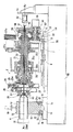
先ず、本発明の一実施形態に係るスピニング加工装置の構成を図1乃至図3を参照して説明すると、図1に示すように、ベースBS上に、本発明の第1の駆動手段たる第1の駆動機構1及び第2の駆動手段たる第2の駆動機構2が構成されている。第1の駆動機構1においては、図1及び図2に示すように管素材4の端部の加工目標の軸XeがX軸となるように(図1では軸Xtと軸Xeは同一面上にあるので一致している)、これと平行に一対のX軸ガイドレール5がベ−スBS上の一方側(図1の右側)に固定され、このX軸ガイドレール5に沿って筐体20が移動可能に配置されている。この筐体20の下部にはボールソケット7が固定され、これに螺合する螺子軸8が、ベ−スBS上にX軸ガイドレール5と平行に配置され、サーボモータ9によって回動可能に支持されている。而して、サーボモータ9によって螺子軸8が回転駆動されると、筐体20はX軸に沿って移動するように構成されている。
【0014】
一方、ベ−スBSの他方側(図1の左側)には台1aが形成されており、X軸ガイドレール5と直交する一対のY軸ガイドレール10が台1a上に固定されている。これらのY軸ガイドレール10には一対のスライダ11が移動可能に配置され、これらのスライダ11上にクランプ装置12が支持されている。クランプ装置12は、スライダ11に固定される下側クランプ13と、その上方に配置される上側クランプ17を備え、これら下側クランプ13と上側クランプ17との間に管素材4が挟持される。下側クランプ13の下部にはボールソケット14(図2)が固定されており、これに螺合する螺子軸15が、台1a上にY軸ガイドレール10と平行に配置され、サーボモータ16によって回動可能に支持されている。而して、サーボモータ16によって螺子軸15が回転駆動されると、クランプ装置12はY軸に沿って移動するように構成されている。
【0015】
上側クランプ17の上部には駆動手段として、例えば油圧駆動のシリンダ18が配置され、これによって上側クランプ17が昇降駆動可能に支持されており、管素材4の装着及び取り外し時には上側クランプ17が上昇駆動される。そして、下側クランプ13の上面には半円筒のクランプ面が形成され、上側クランプ17の下面にも半円筒のクランプ面が形成されており、これらのクランプ面の間に管素材4が挟持されたときには、回転及び移動不能に保持されるように構成されている。また、クランプ装置12の筐体20と反対側にはストッパ19が配設されており、このストッパ19に一端部が衝合するように管素材4が配置される。ストッパ19はクランプ装置12と共に移動し得るように、下側クランプ13に装着されている。尚、ストッパ19を下側クランプ13に対しX軸方向に位置調節可能に構成すれば、管素材4の軸方向の位置決めを適切且つ容易に行なうことができる。
【0016】
而して、管素材4が下側クランプ13のクランプ面上で、ストッパ19に一端部が衝合するように配置された後、上側クランプ17が油圧シリンダ18によって下降駆動されると、管素材4は上側クランプ17と下側クランプ13の間の所定位置に保持される。このとき、図1に示すように、管素材4の軸Xtが後述する主軸21の軸Xrに対し、ベースBSと平行な同一平面上(ベースBSから同一の高さ)に位置するように構成されている。
【0017】
更に、図1の左側のテーブル6には例えばモータ31から成る回転駆動手段が埋設されており、このモータ31の出力軸31aが図1の上方、即ちベースBSに対し垂直方向に延出して下側クランプ13に係合し、この下側クランプ13を出力軸31aを中心に回転駆動し得るように構成されている。テーブル6の上面には、出力軸31aを中心とする円弧状の案内溝32が形成されており、この案内溝32に嵌合するガイドローラ33が下側クランプ13の下面に回動自在に支持されている。而して、下側クランプ13は案内溝32に沿って回動し、出力軸31aを中心として回転駆動される。
【0018】
次に、第2の駆動機構2について説明すると、図1の右側に、主軸21が、管素材4の軸Xtに対してベースBSと平行な同一平面上に位置し、管素材4の加工目標の軸Xeと略同軸上で管素材4に対向するように配置され、その軸Xrを中心にベアリング20a,20bを介して回動自在に筐体20に支持されている。主軸21は中空の円筒状の部材で形成され、その中空部に円筒状のカム軸23が収容され、後述する変速機構50に連結されている。更に、カム軸23の中空部を貫通するようにマンドレル40の連結棒41が軸方向に進退可能に支持されている。マンドレル40は管素材4の開口端内側の形状に合致するように形成されている。連結棒41の基端部は進退駆動用のシリンダ42に支持され、シリンダ42はブラケット1cを介してベースBSに支持されている。
【0019】
主軸21は歯車列22aを介してプーリ22bに連結され、このプーリ22bがベルト(図示せず)を介して回転駆動手段のモータ等(図示せず)等に連結されており、主軸21はこのモータ等によって回転駆動される。一方、主軸21の先端にはフランジ24が固定されており、主軸21が回転駆動されるとフランジ24が軸Xrを中心に回転する。そして、このフランジ24に対して回動可能にカム軸23の先端部が支持されている。カム軸23の先端部にはカム板25が固定されており、カム板25はカム軸23と共に軸Xrを中心に回転駆動される。
【0020】
図3に示すように、カム板25には3条の螺旋状の案内溝25aが形成されており、これらの案内溝25aの各々に、カム板25の回転に伴い径方向に移動する案内ピン26が配置されている。これらの案内ピン26は3個の支持部材27に夫々保持されており、各支持部材27には、図1及び図2に示すようにローラ28が回動自在に支持されている。而して、主軸21が回転駆動されると、ローラ28が軸Xrを中心に回動すると共に、カム板25の回転に応じて支持部材27が径方向に駆動され、ローラ28が管素材4の軸Xrに対して近接、離隔するように駆動される。
【0021】
上記のカム軸23が連結される変速機構50は、撓み噛み合い式駆動装置を用いたもので、主軸21とカム軸23に夫々係合される一対の外輪51,52と、これらの内面に形成された同一の歯数の歯溝に噛合し、これらと異なる歯数の歯形が形成された可撓性の歯車輪53と、この歯車輪53を回動可能に支持し外輪51,52の歯溝と相対する2箇所で噛合するように配置するウェーブ形成輪54が設けられている。このウェーブ形成輪54は駆動用減速モータ55によって回転駆動される。外輪51,52は夫々支持歯車56,57に支持され、支持歯車56と噛合する駆動歯車58が主軸21に取付けられ、支持歯車57と噛合する従動歯車59がカム軸23に取付けられている。
【0022】
上記の撓み噛み合い式駆動装置は、例えば波動歯車装置( Harmonic Drive Systems, Inc. 社の登録商標「ハーモニックドライブ」)として知られているので作動原理の説明は省略するが、主軸21の回転駆動に応じて外輪51,52間に相対速度差が生ずる差動機構が構成されている。而して、主軸21が回転駆動されると、外輪51,52間の差動によりカム軸23を介してカム板25が回転駆動され、各支持部材27、ひいては各ローラ28が主軸21の軸Xrに対し径方向移動するように構成されている。
【0023】
尚、ローラ28は複数でなく一個としてもよいが、断続的な衝撃を和らげるためには複数とすることが望ましい。また、ローラ28は径方向に変位可能であればどのような移動経路としてもよい。ローラ28の駆動手段としては遊星歯車機構等、他の手段を用いることとしてもよい。
【0024】
上記モータ9,16,31等及びシリンダ18等の各駆動手段はコントローラ(図示せず)に電気的に接続され、このコントローラから各駆動手段に対し制御信号が出力され、数値制御されるように構成されている。
【0025】
上記スピニング加工装置により管素材の端部に対し偏心軸を中心に縮径を行なう場合の一例を図4を参照して説明する。図4の太い実線は加工後の管素材4を想定した外形を示し、本体部(胴部)4aと、縮径部を構成するテーパ部4bo及び首部4coが表れている。先ず、管素材4の先端から加工長(L1)後退した位置が加工開始点O1とされる。そして、テーパ部4boを加工する際には、偏心量(H)が所定の加工サイクル回数N(図4の例では5回)で分割され、この間の1サイクル当りの偏心方向移動量、即ちY軸方向の移動量(H1)が設定される。
【0026】
尚、本実施形態では図4に示すように移動量(H)を等分割としたが、要求される加工方法に応じて分割割合を異ならせることとしてもよい。例えば、加工初期のサイクル間の移動量を大きくして加工時間を短縮したり、加工終期のサイクル間の移動量を小さくして仕上げ精度を向上させることができる。同様に、軸方向長さに関し、テーパ長(LT)が加工サイクル回数N(5回)で分割され、この間の1サイクル当りのX軸方向の移動量(X1)が設定される。
【0027】
図4において、Dは管素材4の本体部4aの直径、RDはテーパ部4boの最小直径で、首部4coの直径を表す。また、V1は加工量の多い側の縮径量を表し、V2は加工量の少ない側の縮径量を表す。そして、CY1乃至CY5は加工サイクルを表している。加工サイクル回数Nは、管素材4の縮径加工限界に鑑み、適宜設定されるが、本実施形態では1サイクル当りの移動量が管素材4の縮径加工限界を越えない値に設定する必要がある。この縮径加工限界は、管素材4の材質に起因して塑性加工を適切に行なうことができなくなる限界であり、これを越えて縮径加工を行なうと材料の薄肉化や破損を惹起することになる。
【0028】
而して、図1において、先ず上側クランプ17が上昇した状態で、下側クランプ13のクランプ面13a上に加工対象の管素材4が配置され、ストッパ19に当接した状態の所定位置でシリンダ18が駆動される。これにより、上側クランプ17が下降し、管素材4は下側クランプ13と上側クランプ17の間に挟持され、回転不能の状態で保持される。このとき、管素材4の軸Xtが主軸21の軸Xrと同軸となるように位置決めされる(図2の状態とは異なる)。また、各ローラ28は管素材4の外径よりも外側に退避している。
【0029】
次に、筐体20がX軸ガイドレール5に沿って前進駆動され(図1及び図2の左方向に移動)、管素材4の先端から加工長(図4のL1)後退した点に各ローラ28が位置した状態で停止される。換言すれば、各ローラ28は図4の加工開始点O1に位置しており、この位置が原位置に設定される。そして、クランプ装置12がY軸ガイドレール10に沿って駆動され(図2の下方に移動)、管素材4が1サイクル当りの偏心方向移動量(H1)だけ、Y軸方向に移動した位置で停止される。尚、このときの管素材4の軸Xtを主軸21の軸Xrに対し移動量(H1)だけY軸方向に移動した位置を管素材4の原位置とするように設定してもよい。そして、マンドレル40が管素材4の先端部開口内に位置するように前進駆動される。
【0030】
この状態から、主軸21が回転駆動され、各ローラ28が軸Xrを中心に回動すると共に、変速機構50を介してカム板25が回転駆動され、各ローラ28が主軸21の軸Xr方向に移動する。同時に、筐体20ひいては各ローラ28がX軸ガイドレール5に沿って後退駆動される(図1及び図2の右方向に移動)。これにより、各ローラ28は、管素材4の端部の外周面に圧接された状態で、それ自体回転すると共に軸Xrを中心に主軸21回りを回転しながら、軸Xr方向に径方向駆動され、スピニング加工が行なわれる。
【0031】
この場合において、各ローラ28が加工開始点O1から移動量(X1)を移動し、各ローラ28が所定量を移動するまでは、ローラ28の回転軸たる軸Xrが管素材4の軸Xtに対し移動量(H1)だけ相対的にオフセット(偏心)しているため、スピニング加工によって管素材4の端部が塑性変形されると、図5の(CY1)に示すように、本体部4aの軸Xtに対しH1だけ偏心した軸を中心とする裁頭円錐状のテーパ部4bo1 が形成される。
【0032】
そして、各ローラ28が移動量(X1)を越えて更に後退駆動されるときには、各ローラ28はその状態(所定量移動した位置)に保持される。従って、各ローラ28の後退駆動によって管素材4の先端部が塑性変形し、テーパ部4bo1 の最小径部に連続して本体部4aの軸Xtに対しH1だけ偏心した軸を中心とする円筒状の首部4co1 が形成される。この後、管素材4とローラ28が、原位置に復帰駆動され、上記の縮径作動の往動パスと共に1往復移動が1サイクルとされ、第1サイクル(CY1)のスピニング加工が終了する。尚、本実施形態では説明の便宜上、往動パスにおける縮径作動のみを説明したが、復動パスにおいても同様の加工を行ない、1サイクル中の2パスともスピニング加工を行なうように設定することとすれば、加工効率が良好となる。また、ローラ28は、エネルギー効率やタクトタイムに鑑み、各サイクル毎に停止させることなく、連続して回転するように設定されている。
【0033】
第1サイクル(CY1)のスピニング加工が終了し各ローラ28が原位置に復帰駆動された後、第2サイクル(CY2)のスピニング加工が行なわれる。即ち、筐体20(各ローラ28)が前進駆動され、管素材4の先端から加工長(L1−X1)後退した位置に各ローラ28が位置した状態で停止される。同時に、クランプ装置12がY軸ガイドレール10に沿って駆動され、管素材4が移動量(2・H1)だけY軸方向に移動した位置で停止される。この状態から、各ローラ28が軸Xr方向に径方向駆動されると共に、各ローラ28がX軸ガイドレール5に沿って後退駆動される。
【0034】
これにより、前述のように各ローラ28が管素材4の外周面に圧接された状態で軸Xr方向に径方向駆動され、スピニング加工が行なわれる。この場合において、各ローラ28が加工開始点O1から所定量(第1サイクル(CY1)時の2倍(2・X1))を移動するまでは、各ローラ28の回転軸の軸Xrが管素材4の軸Xtに対し移動量(2・H1)だけ偏心しているため、スピニング加工された管素材4の端部は、本体部4aの軸Xtに対し2・H1だけ偏心した軸を中心とするテーパ部及び首部が形成される。而して、本実施形態では上記と同様の工程が更に3回繰り返されると、図5の(CY5)に示すように、偏心軸を有するテーパ部4bo及び首部4coから成る縮径部4doが、管素材4の端部に形成される。
【0035】
次に、上記スピニング加工装置により管素材の端部に対し傾斜軸を中心に縮径を行なう場合の一例を図1及び図2並びに図6乃至図8を参照して説明する。図1において、前述のように管素材4が下側クランプ13と上側クランプ17の間に保持された状態で、テーブル6がモータ16によってY軸ガイドレール10に沿って駆動されると共に、下側クランプ13がモータ31によって出力軸31aを中心に回転駆動され、図2に示すように管素材4の軸Xtに対して傾斜した加工目標の軸Xeが主軸21の軸Xrと同軸となるように位置決めされる。そして、マンドレル40が管素材4の端部開口内に位置するように前進駆動される。
【0036】
このときの同管素材4とローラ28の関係、及び軸Xe、軸Xr及び軸Xtの関係は図6に示すようになる。同図において、点C0は下側クランプ13の回転中心で出力軸31aに対応しており、主軸21の軸Xrに対して管素材4の軸Xtがθ角度傾斜している。点C1は、加工目標とする管素材4の傾斜端部における最内側端面の中心であり、点C0と点C1との間が距離R1だけ離れている。前述のように主軸21の軸Xrはベ−スBSに平行な面上に配置されるのに対し、管素材4は出力軸31a、即ち点C0を中心に回動し、軸Xtと軸Xrとの間に傾斜角θが形成されている。
【0037】
上記の関係から明らかなように、軸Xrに平行で傾斜端部の中心点C1を含む加工目標の軸Xeは、軸Xrに対して垂直な方向に、即ちY軸に沿って距離Sだけ離れている。この距離SはS=R1・sinθとして求められる。従って、例えば各ローラ28が軸Xr方向に駆動されると、その軌跡は図6に2点鎖線で示すようになるので、管素材4の端部が適切に加工されない。管素材4の端部を適切な形状に形成するためには、主軸21を軸Xeと略同軸に配置する必要がある。
【0038】
このため、本実施形態では軸Xeが加工目標として用いられ、管素材4がY軸ガイドレール10に沿って軸Xrに対して垂直な方向に、即ち図6の下方に駆動され、距離Sだけ平行移動した位置とされる。これにより、主軸21(軸Xrで表す)と管素材4の関係は図7に示すようになり、軸Xrと加工目標の軸Xeが重合する。図7に2点鎖線で示す5本の軌跡のうち最終軌跡(最内側)が目標とする外形を表し、その中心軸が加工目標の軸Xeに対応し、形成される縮径部の傾斜軸に対応している。
【0039】
この状態から、主軸21が軸Xrを中心に回転駆動され、各ローラ28が軸Xr(軸Xe)を中心に回動すると共に、変速機構50を介してカム板25が回転駆動され、各ローラ28が軸Xr方向に移動する。同時に、各ローラ28がX軸ガイドレール5に沿って後退駆動される(図1及び図2の右方向に移動)。これにより、各ローラ28は、管素材4の端部の外周面に圧接された状態で、それ自体回転すると共に軸Xrを中心に回転しながら、軸Xr方向に径方向駆動され、スピニング加工が行なわれる。而して、図8に示すように管素材4の端部はテーパ部4brと、軸Xtに対して傾斜した軸Xeを中心とする首部4crから成る縮径部4drが形成される。
【0040】
前述のように管素材4の端部に対し偏心軸を中心に縮径を行なうと共に、傾斜軸を中心に縮径を行なうこととすれば、所望の縮径部を一層容易且つ迅速に形成することができる。例えば、図9に示すように、図4及び図5の縮径工程によって偏心軸を中心にテーパ部4boと首部4coが端部に形成された管素材4に対し、傾斜軸を中心に縮径を行なうことにより、図9に2点鎖線で示すように偏心軸及び傾斜軸を中心に目標の外形に形成することができる。
【0041】
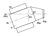
次に、主軸21の軸XrがベースBSに対し平行な面に配置されるのに対し、管素材4は点C0を中心に所定角度(θ)回転され、図12に示すように傾斜角θが形成される。このとき、傾斜軸、即ち加工目標の軸Xeは、軸Xrと平行で、管素材4の目標とする端部の最内側の断面の中心C1を含むように設定される。この中心C1は、軸Xrに対し距離S(=R1・sinθ)だけY軸方向に離れている。従って、前述のように、管素材4はY軸ガイドレール10に沿って軸Xrに対して垂直方向(図12の下方)に距離Sだけ駆動され、軸Xrと加工目標の軸Xeが重合する。
【0042】
而して、図13に2点鎖線で示すように、各ローラ28が管素材4の外面に当接した状態で、それ自体回転すると共に軸Xr(加工目標の軸Xeと重合)を中心に回転しながら、軸Xr方向に径方向駆動され、スピニング加工が行なわれる。この結果、図12に示すように、管素材4の軸Xtに対して傾斜した軸Xeを中心にテーパ部4bp及び首部4cpが管素材4の端部に形成される。この後、管素材4の先端部が切除されて、図11に示すテーパ部4bp及び首部4cpを備えた管素材4が形成される。
【0043】
而して、本実施形態の縮径加工によれば偏心軸と傾斜軸の各々を中心としてスピニング加工が行なわれるので、所望の形状の端部が容易に形成され、滑らかな加工面が得られる。しかも、ローラ28等に対する負荷が過大となることがないので、円滑に加工作業を行なうことができる。特に、本実施形態は、縮径部の傾斜角度が小さい製品を製造する場合に、迅速且つ容易に滑らかな加工面を有する縮径部を形成することができる。また、マンドレル40の直径は、管素材4の加工後の首部4cpの内径と等しい値に設定されており、仕上げ加工時には、首部4cpがマンドレル40とローラ28に挟持された状態でスピニング加工が行なわれるので、首部4cpを容易に滑らかな面に形成することができる。
【0044】
尚、製造時間と製品の品質を勘案すると、管素材の端部に対し偏心軸を中心に縮径する工程は複数回とし、管素材の端部に対し傾斜軸を中心に縮径する工程は1回とするとよい。但、管素材4の軸Xtに対する縮径部の傾斜軸の角度を大きく形成する必要がある場合には、スピニング工程時に、あるいは更に1サイクル毎に、テーブル6をモータ31の出力軸31aを中心に所定角度づつ回転させると共にY軸方向に所定距離づつ移動させ乍ら、スピニング加工を行なうこととするとよい。
【0045】
図1及び図2の実施形態においては筐体20がX軸に沿って駆動されると共に、管素材4がY軸に沿って駆動されることによって、両者が相対的に移動するように構成されているが、筐体20をベ一スBS上に固定し、管素材4をX軸及びY軸に沿って駆動するように構成してもよい。即ち、本発明の第1の駆動手段たる第1の駆動機構1を図1の左側に集中して配置することとしてもよい。
【0046】
また、図1及び図2に記載の実施形態においては、管素材4の軸Xtが主軸21の軸Xrに対し、ベースBSと平行な同一平面上に位置するように、ベースBSからの高さが固定されているが、管素材4の軸XtのベースBSからの高さを可変とし、主軸21の軸Xrに対し鉛直方向にも調整可能に構成してもよい。即ち、本実施形態は管素材4を鉛直方向に駆動する駆動機構(図示せず)を付加することとすれば、調整が一層容易となる。
【0047】
【発明の効果】
本発明は上述のように構成されているので以下に記載の効果を奏する。即ち、請求項1及び請求項3に記載の管素材の端部成形方法及び装置においては、偏心軸を中心にローラと管素材を相対的に回転駆動すると共にローラを主軸に向かって径方向に駆動し、且つ傾斜軸を中心にローラと管素材を相対的に回転駆動すると共にローラを主軸に向かって径方向に駆動して管素材に対しスピニング加工を行なうように構成されており、端部に対し円滑且つ効率的にスピニング加工が行なわれるので、管素材の端部に縮径部を容易に一体的に形成することができ、縮径部に対し滑らかな加工面を確保することができる。特に、縮径部の傾斜角度が小さい製品を製造する場合に有効であり、迅速且つ容易に縮径部を形成することができ、高精度で所望の形状に形成することができる。勿論、従来のような溶接等の接合作業が不要であるので、製造が容易であり製造コストを低減することができる。
【0048】
また、請求項2及び請求項4に記載の成形方法及び装置においては、管素材の軸に対する縮径部の軸の傾斜角度が大きい場合でも、円滑にスピニング加工を行なうことができ、縮径部に対し滑らかな加工面を確保することができる。
【0049】
更に、請求項5に記載の装置においては、一層円滑なスピニング加工を行なうことができ、縮径部に対し滑らかな加工面を確保することができる。
【図面の簡単な説明】
【図1】本発明の一実施形態に係るスピニング加工装置の一部を破断した状態を示す側面図である。
【図2】本発明の一実施形態に係るスピニング加工装置の一部を破断した状態を示す平面図である。
【図3】本発明の一実施形態におけるカム板及び支持部材を示す正面図である。
【図4】本発明の一実施形態のスピニング加工装置により管素材の端部に対し偏心軸を中心に縮径を行なう場合の一例を示す説明図である。
【図5】本発明の一実施形態のスピニング加工装置により管素材の端部に対し偏心軸を中心に縮径を行なう際の工程毎の管素材の端部形状を示す正面及び側面図である。
【図6】本発明の一実施形態のスピニング加工装置により管素材の端部に対し傾斜軸を中心に縮径を行なう場合の一例を示す平面図である。
【図7】本発明の一実施形態のスピニング加工装置により管素材の端部に対し傾斜軸を中心に縮径を行なう場合の一例を示す平面図である。
【図8】本発明の一実施形態のスピニング加工装置により形成された傾斜軸を中心に端部を備えた管素材を示す平面図である。
【図9】本発明の一実施形態のスピニング加工装置により管素材の端部に対し偏心軸及び傾斜軸を中心に縮径を行なう際の、偏心軸を中心に端部が形成された管素材を示す一例を示す平面図である。
【図10】本発明の一実施形態のスピニング加工装置により、偏心軸を中心に端部が形成された管素材に対し、更に傾斜軸を中心に縮径を行なう状態の管素材を示す平面図である。
【図11】本発明の一実施形態のスピニング加工装置により、偏心軸を中心に端部が形成された管素材に対し、更に傾斜軸を中心に縮径を行なう状態の管素材を示す平面図である。
【図12】本発明の一実施形態のスピニング加工装置により、偏心軸を中心に端部が形成された管素材に対し、更に傾斜軸を中心に縮径を行なった管素材を示す平面図である。
【図13】本発明の一実施形態のスピニング加工装置により形成された偏心軸及び傾斜軸を中心に端部が形成された管素材を示す平面図である。
【符号の説明】
1 第1の駆動機構, 2 第2の駆動機構, 4 管素材,
4bo,4br,4bp テーパ部, 4co,4cr,4cp 首部,
9,16,31,55 モータ, 18,25 シリンダ,
12 クランプ装置, 21 主軸, 28 ローラ,
32 案内溝, 33 ガイドローラ, 50 変速機構[0001]
BACKGROUND OF THE INVENTION
The present invention relates to an end forming method and apparatus for a tube material, and more particularly to an end forming method and an end forming apparatus for integrally forming a reduced diameter portion at an end of a cylindrical metal tube material.
[0002]
[Prior art]
As an end molding method for forming a reduced diameter portion at the end of a cylindrical metal tube material (hereinafter referred to as a tube material), for example, Japanese Utility Model Publication No. 61-110823 discloses at least one cone portion and a main body. A catalyst carrier holding case integrally formed by expanding or contracting a pipe material is disclosed, and the portion on the opening end side of the cylindrical portion is contracted by spinning while leaving the case main body portion, and further the other cone portion A method of integrally forming a conduit connected thereto is disclosed. Japanese Patent Laid-Open No. 3-226327 discloses that a pipe material is pressed in the axial direction by a press die to be formed into a substantially conical shape, and then the pipe material is rotatably supported and a spinning roll is formed on the outer peripheral surface of the conical formed portion. A method for forming a mouth portion of a pressure vessel or the like for spinning by pressing is disclosed.
[0003]
[Problems to be solved by the invention]
By the way, regarding the catalytic converter in the exhaust system of the silencer of an automobile and the outer cylinder of the silencer, it is intended to improve the ease of manufacture and the vehicle mountability, and it is desired to integrally form these from a metal tube material. . Under such circumstances, it is required that the reduced diameter portion formed at the end of the tube material can be formed into a special shape such as being eccentric or inclined with respect to the axis of the tube material.
[0004]
However, in the conventional forming method by spinning, the reduced diameter portion coaxial with the main body portion is formed on the tube material. When the main body portion and the reduced diameter portion are not coaxial, Japanese Utility Model Laid-Open No. 61-110823 described above. 1 was formed by press work like the cone portion (reduced diameter portion) on the right side of FIG. 1, and this was welded to the case body. However, the tube formed by such a method cannot be as strong as the integral molding, and requires a different operation of joining, so that it is difficult to manufacture, and a coaxial tube formed by spinning processing. The increase in manufacturing cost is inevitable compared to the body.
[0005]
Then, this invention makes it a subject to provide the edge part shaping | molding method and apparatus of a pipe | tube raw material which can form a diameter-reduced part integrally and easily in the edge part of a pipe | tube raw material.
[0006]
[Means for Solving the Problems]
In order to solve the above-described problems, a method for forming an end portion of a pipe material according to the present invention supports a roller so as to be movable in a radial direction with respect to a main shaft and forms a pipe on a surface including the main shaft. The tube material is supported so that the shaft of the material is positioned, and the roller and the tube material are driven to rotate relative to each other about the eccentric shaft that is eccentric with respect to the shaft of the tube material, and the roller is The roller is driven radially toward the main shaft so as to contact the outer peripheral surface of the end portion, and the roller and the tube material are relatively moved around an inclined axis inclined with respect to the axis of the tube material. Spinning is performed on the tube material by driving the roller in a radial direction toward the main shaft so that the roller contacts the outer peripheral surface of the end portion of the tube material. The reduced diameter part is formed in the part. .
[0007]
In the method of forming an end portion of the tube material, as described in
[0008]
According to another aspect of the present invention, there is provided an apparatus for forming an end portion of a pipe material, wherein a main shaft, a roller that supports the main shaft so as to be movable in a radial direction, and a pipe material on a surface including the main shaft. The tube material is supported so that the axis of the tube material is positioned, and the main shaft is substantially coaxial with an eccentric shaft that is eccentric with respect to the tube material axis and an inclined shaft that is inclined with respect to the tube material axis. A first driving means for relatively driving the main shaft and the tube material; and an outer peripheral surface of an end portion of the tube material while the roller and the tube material are driven to rotate relative to each other about the eccentric shaft. The roller is driven in a radial direction toward the main shaft so as to abut against the main shaft, and the roller and the tube material are driven to rotate relative to each other about the inclined shaft. The roller is moved toward the main shaft so as to contact the outer peripheral surface. Second driving means for driving in the direction, and controlling the second driving means and the first driving means to form a reduced diameter portion at the end of the tube material. .
[0009]
Thus, the first driving means relatively drives the main shaft and the tube material so that the main axis is substantially coaxial with the eccentric shaft, and the second driving means causes the roller and the The tube material is driven to rotate relative to the eccentric shaft, and the roller is driven in a radial direction toward the main shaft so as to abut on the outer peripheral surface of the end portion of the tube material. A central reduced diameter portion is formed. Moreover, the main shaft and the tube material are relatively driven by the first driving means so that the main shaft is substantially coaxial with the inclined axis, and the roller and the tube material are driven by the second driving means. Is driven to rotate relative to the tilt axis, and the roller is driven in a radial direction toward the main shaft so as to contact the outer peripheral surface of the end portion of the tube material. A reduced diameter portion is formed. The first driving means is any one of a mechanism for driving the roller with respect to the tube material, a mechanism for driving the tube material with respect to the roller, and a mechanism for driving both the tube material and the roller. be able to.
[0010]
In the tube material end forming apparatus, as described in
[0011]
Further, in the tube material end forming apparatus according to
[0012]
DETAILED DESCRIPTION OF THE INVENTION
An embodiment of a method and an apparatus for forming an end portion of a tube material having the above-described configuration will be described with reference to the drawings. FIG. 1 to FIG. 3 show a spinning processing apparatus used in one embodiment of an end forming apparatus for a tube material. The final product of this embodiment is, for example, an outer cylinder (not shown) of a silencer for automobiles or a catalyst. Used for converters. In this embodiment, the tube material to be processed is a stainless steel tube, but is not limited thereto, and other metal tubes may be used.
[0013]
First, the configuration of a spinning processing apparatus according to an embodiment of the present invention will be described with reference to FIGS. 1 to 3. As shown in FIG. 1, a first driving means of the present invention is formed on a base BS. A
[0014]
On the other hand, a
[0015]
For example, a hydraulically driven
[0016]
Thus, after the
[0017]
Further, the table 6 on the left side of FIG. 1 is embedded with a rotary drive means comprising, for example, a
[0018]
Next, the
[0019]
The
[0020]
As shown in FIG. 3, the
[0021]
The
[0022]
The above-described bending engagement type driving device is, for example,Wave gear device ( Harmonic Drive Systems, Inc. The registered trademark “Harmonic drive")Known assoAlthough a description of the operation principle is omitted, a differential mechanism in which a relative speed difference is generated between the
[0023]
The number of
[0024]
The driving means such as the
[0025]
An example in which the diameter is reduced around the eccentric shaft with respect to the end portion of the pipe material by the spinning processing apparatus will be described with reference to FIG. The thick solid line in FIG. 4 shows the outer shape assuming the processed
[0026]
In the present embodiment, the movement amount (H) is equally divided as shown in FIG. 4, but the dividing ratio may be varied according to the required processing method. For example, the machining amount can be shortened by increasing the amount of movement between cycles at the beginning of machining, or the finishing amount can be improved by reducing the amount of movement between cycles at the end of machining. Similarly, with respect to the axial length, the taper length (LT) is divided by the number of machining cycles N (5 times), and the amount of movement (X1) in the X-axis direction per cycle during this period is set.
[0027]
In FIG. 4, D is the diameter of the
[0028]
Thus, in FIG. 1, the
[0029]
Next, the
[0030]
From this state, the
[0031]
In this case, each
[0032]
When each
[0033]
After the spinning process of the first cycle (CY1) is completed and each
[0034]
Thus, as described above, each
[0035]
Next, an example in which the diameter of the end of the tube material is reduced around the inclined axis by the spinning device will be described with reference to FIGS. 1 and 2 and FIGS. In FIG. 1, with the
[0036]
The relationship between the
[0037]
As is apparent from the above relationship, the machining target axis Xe parallel to the axis Xr and including the center point C1 of the inclined end portion is separated by a distance S in a direction perpendicular to the axis Xr, that is, along the Y axis. ing. This distance S is obtained as S = R1 · sin θ. Therefore, for example, when each
[0038]
For this reason, in this embodiment, the axis Xe is used as a machining target, and the
[0039]
From this state, the
[0040]
As described above, if the diameter of the end portion of the
[0041]
Next, while the axis Xr of the
[0042]
Thus, FIG.3As indicated by a two-dot chain line, each
[0043]
Thus, according to the diameter reduction processing of the present embodiment, since the spinning processing is performed around each of the eccentric shaft and the inclined shaft, an end portion of a desired shape is easily formed, and a smooth processing surface is obtained. . In addition, since the load on the
[0044]
In consideration of the manufacturing time and product quality, the process of reducing the diameter around the eccentric axis with respect to the end of the tube material is performed a plurality of times, and the process of reducing the diameter around the inclined axis with respect to the end of the tube material is performed One time is good. However, if it is necessary to increase the angle of the inclined axis of the reduced diameter portion with respect to the axis Xt of the
[0045]
1 and 2, the
[0046]
Further, in the embodiment described in FIGS. 1 and 2, the height from the base BS is such that the axis Xt of the
[0047]
【The invention's effect】
Since this invention is comprised as mentioned above, there exists an effect as described below. That is, in the tube material end forming method and apparatus according to
[0048]
Further, in the molding method and apparatus according to
[0049]
Furthermore, in the apparatus according to the fifth aspect, a smoother spinning process can be performed, and a smooth machined surface can be secured for the reduced diameter portion.
[Brief description of the drawings]
FIG. 1 is a side view showing a state in which a spinning processing apparatus according to an embodiment of the present invention is partially broken.
FIG. 2 is a plan view showing a state in which a part of the spinning processing apparatus according to the embodiment of the present invention is broken.
FIG. 3 is a front view showing a cam plate and a support member in an embodiment of the present invention.
FIG. 4 is an explanatory view showing an example in which the diameter of the end portion of the pipe material is reduced around the eccentric shaft by the spinning processing apparatus according to the embodiment of the present invention.
FIGS. 5A and 5B are a front view and a side view showing an end shape of a tube material for each process when the diameter of the end of the tube material is reduced about an eccentric shaft with respect to the end portion of the tube material by the spinning device according to the embodiment of the present invention. .
FIG. 6 is a plan view showing an example in which the diameter of the end portion of the tube material is reduced around the inclined axis by the spinning processing apparatus according to the embodiment of the present invention.
FIG. 7 is a plan view showing an example in which the diameter of the end portion of the tube material is reduced around the inclined axis by the spinning processing apparatus according to the embodiment of the present invention.
FIG. 8 is a plan view showing a tube material having an end portion around an inclined axis formed by a spinning processing apparatus according to an embodiment of the present invention.
FIG. 9 shows a pipe material having an end portion formed around the eccentric shaft when the diameter of the end portion of the pipe material is reduced around the eccentric shaft and the inclined shaft by the spinning processing apparatus according to the embodiment of the present invention. It is a top view which shows an example which shows.
FIG. 10 is a plan view showing a tube material in a state in which the diameter is further reduced around an inclined axis with respect to the tube material having an end portion formed around an eccentric shaft by the spinning processing apparatus according to the embodiment of the present invention. It is.
FIG. 11 is a plan view showing a pipe material in a state in which the diameter is further reduced around an inclined axis with respect to the pipe material having an end formed around an eccentric axis by the spinning processing apparatus according to the embodiment of the present invention. It is.
FIG. 12 is a plan view showing a tube material in which the diameter is further reduced around an inclined axis with respect to the tube material having an end formed around an eccentric axis by a spinning processing apparatus according to an embodiment of the present invention. is there.
FIG. 13 is a plan view showing a tube material having ends formed around an eccentric shaft and an inclined shaft formed by the spinning processing apparatus according to the embodiment of the present invention.
[Explanation of symbols]
1 first drive mechanism, 2 second drive mechanism, 4 pipe material,
4bo, 4br, 4bp taper part, 4co, 4cr, 4cp neck part,
9, 16, 31, 55 motor, 18, 25 cylinders,
12 clamping devices, 21 spindles, 28 rollers,
32 guide grooves, 33 guide rollers, 50 speed change mechanism
Claims (5)
Priority Applications (1)
| Application Number | Priority Date | Filing Date | Title |
|---|---|---|---|
| JP37659598A JP4086394B2 (en) | 1998-12-24 | 1998-12-24 | End material forming method and apparatus for tube material |
Applications Claiming Priority (1)
| Application Number | Priority Date | Filing Date | Title |
|---|---|---|---|
| JP37659598A JP4086394B2 (en) | 1998-12-24 | 1998-12-24 | End material forming method and apparatus for tube material |
Publications (3)
| Publication Number | Publication Date |
|---|---|
| JP2000190030A JP2000190030A (en) | 2000-07-11 |
| JP2000190030A5 JP2000190030A5 (en) | 2006-02-02 |
| JP4086394B2 true JP4086394B2 (en) | 2008-05-14 |
Family
ID=18507412
Family Applications (1)
| Application Number | Title | Priority Date | Filing Date |
|---|---|---|---|
| JP37659598A Expired - Lifetime JP4086394B2 (en) | 1998-12-24 | 1998-12-24 | End material forming method and apparatus for tube material |
Country Status (1)
| Country | Link |
|---|---|
| JP (1) | JP4086394B2 (en) |
Cited By (3)
| Publication number | Priority date | Publication date | Assignee | Title |
|---|---|---|---|---|
| CN103736890A (en) * | 2013-12-30 | 2014-04-23 | 太原科技大学 | Hammerhead subsection tilting type seamless steel tube hot heading machine |
| CN106391892A (en) * | 2016-08-31 | 2017-02-15 | 安徽金三环金属科技有限公司 | Cold-stamping necking equipment |
| JP2018144063A (en) * | 2017-03-03 | 2018-09-20 | 株式会社三五 | Spinning machining method and cylindrical body having head-cut cone part at end part |
Families Citing this family (9)
| Publication number | Priority date | Publication date | Assignee | Title |
|---|---|---|---|---|
| JP3027581B1 (en) * | 1999-06-21 | 2000-04-04 | 株式会社三五 | Pipe material expansion processing method and pipe material expansion processing device |
| ATE523272T1 (en) | 2002-01-17 | 2011-09-15 | Quide B V | METHOD AND MOLDING MACHINE FOR PRODUCING A PRODUCT OF VARIOUS DIAMETER |
| NL1020171C2 (en) * | 2002-03-13 | 2003-09-16 | Johan Massee | Method and forming machine for machining a workpiece. |
| JP5143338B2 (en) * | 2004-12-27 | 2013-02-13 | 株式会社三五 | Method and apparatus for forming different diameter parts of workpiece |
| US7530253B2 (en) * | 2005-09-09 | 2009-05-12 | Edwards Lifesciences Corporation | Prosthetic valve crimping device |
| CN102350446A (en) * | 2011-10-25 | 2012-02-15 | 张铮 | Rotary roller head making machine |
| CN102688923B (en) * | 2012-05-29 | 2013-09-04 | 江阴圆方机械制造有限公司 | Steel pipe heading machine |
| US20200080840A1 (en) * | 2016-12-20 | 2020-03-12 | Jfe Steel Corporation | Method of evaluating deformability of steel pipe and method of manufacturing steel pipe |
| CN106694721B (en) * | 2017-01-16 | 2018-09-25 | 上海佳方钢管集团太仓有限公司 | A kind of spinning machine and its spin-on process of large diameter steel pipe spigot-and-socket joint |
-
1998
- 1998-12-24 JP JP37659598A patent/JP4086394B2/en not_active Expired - Lifetime
Cited By (4)
| Publication number | Priority date | Publication date | Assignee | Title |
|---|---|---|---|---|
| CN103736890A (en) * | 2013-12-30 | 2014-04-23 | 太原科技大学 | Hammerhead subsection tilting type seamless steel tube hot heading machine |
| CN103736890B (en) * | 2013-12-30 | 2016-10-26 | 太原科技大学 | A kind of determination method of seamless steel pipe hot heading machine tup arm segmentation oblique form |
| CN106391892A (en) * | 2016-08-31 | 2017-02-15 | 安徽金三环金属科技有限公司 | Cold-stamping necking equipment |
| JP2018144063A (en) * | 2017-03-03 | 2018-09-20 | 株式会社三五 | Spinning machining method and cylindrical body having head-cut cone part at end part |
Also Published As
| Publication number | Publication date |
|---|---|
| JP2000190030A (en) | 2000-07-11 |
Similar Documents
| Publication | Publication Date | Title |
|---|---|---|
| JP2957154B2 (en) | Pipe end forming method and apparatus | |
| KR100492486B1 (en) | Method and apparatus for forming end of pipe material | |
| EP1074704B1 (en) | Method of producing a catalytic converter | |
| JP4086394B2 (en) | End material forming method and apparatus for tube material | |
| US6386010B1 (en) | Spinning processing method and apparatus therefor | |
| US6591498B2 (en) | Method of producing a catalytic converter | |
| US6233993B1 (en) | Method and apparatus for forming a processed portion of a workpiece | |
| JP2957153B2 (en) | Pipe end forming method and apparatus | |
| JP4116723B2 (en) | End forming method for tube material | |
| EP1151812B1 (en) | Spinning device | |
| JP3367939B2 (en) | Manufacturing method of catalytic converter | |
| JP3442666B2 (en) | End forming method and apparatus for tube material | |
| JP3378614B2 (en) | Method of manufacturing a hollow workpiece having at least an inner surface having a molded portion extending straight in the axial direction of the workpiece or a molded portion extending obliquely to the axis of the workpiece. | |
| JP3390725B2 (en) | Method and apparatus for forming work of different diameter | |
| KR20040000464A (en) | Hollow product, method and apparatus for manufacturing the hollow product, and fluid transporting system using the hollow product | |
| JP2001047162A (en) | Spinning device | |
| JP5099955B2 (en) | Molding machine and method for deforming hollow processed member | |
| JP4456208B2 (en) | Spinning processing equipment | |
| CA2415936C (en) | Method and forming machine for deforming a hollow workpiece | |
| JP3299974B2 (en) | Method of rolling bevel gear in axial die mill and tool unit for carrying out the method | |
| JP4450504B2 (en) | Workpiece edge forming method | |
| JP2007125579A (en) | Forming method and forming apparatus | |
| JP4683519B2 (en) | Manufacturing method of exhaust system parts |
Legal Events
| Date | Code | Title | Description |
|---|---|---|---|
| A521 | Written amendment |
Free format text: JAPANESE INTERMEDIATE CODE: A523 Effective date: 20051206 |
|
| A621 | Written request for application examination |
Free format text: JAPANESE INTERMEDIATE CODE: A621 Effective date: 20051206 |
|
| A977 | Report on retrieval |
Free format text: JAPANESE INTERMEDIATE CODE: A971007 Effective date: 20070910 |
|
| A131 | Notification of reasons for refusal |
Free format text: JAPANESE INTERMEDIATE CODE: A131 Effective date: 20070918 |
|
| TRDD | Decision of grant or rejection written | ||
| A01 | Written decision to grant a patent or to grant a registration (utility model) |
Free format text: JAPANESE INTERMEDIATE CODE: A01 Effective date: 20080212 |
|
| A61 | First payment of annual fees (during grant procedure) |
Free format text: JAPANESE INTERMEDIATE CODE: A61 Effective date: 20080219 |
|
| FPAY | Renewal fee payment (event date is renewal date of database) |
Free format text: PAYMENT UNTIL: 20110228 Year of fee payment: 3 |
|
| R150 | Certificate of patent or registration of utility model |
Free format text: JAPANESE INTERMEDIATE CODE: R150 |
|
| FPAY | Renewal fee payment (event date is renewal date of database) |
Free format text: PAYMENT UNTIL: 20110228 Year of fee payment: 3 |
|
| S531 | Written request for registration of change of domicile |
Free format text: JAPANESE INTERMEDIATE CODE: R313532 |
|
| FPAY | Renewal fee payment (event date is renewal date of database) |
Free format text: PAYMENT UNTIL: 20110228 Year of fee payment: 3 |
|
| R360 | Written notification for declining of transfer of rights |
Free format text: JAPANESE INTERMEDIATE CODE: R360 |
|
| FPAY | Renewal fee payment (event date is renewal date of database) |
Free format text: PAYMENT UNTIL: 20110228 Year of fee payment: 3 |
|
| R370 | Written measure of declining of transfer procedure |
Free format text: JAPANESE INTERMEDIATE CODE: R370 |
|
| S531 | Written request for registration of change of domicile |
Free format text: JAPANESE INTERMEDIATE CODE: R313532 |
|
| FPAY | Renewal fee payment (event date is renewal date of database) |
Free format text: PAYMENT UNTIL: 20110228 Year of fee payment: 3 |
|
| R350 | Written notification of registration of transfer |
Free format text: JAPANESE INTERMEDIATE CODE: R350 |
|
| FPAY | Renewal fee payment (event date is renewal date of database) |
Free format text: PAYMENT UNTIL: 20140228 Year of fee payment: 6 |
|
| R250 | Receipt of annual fees |
Free format text: JAPANESE INTERMEDIATE CODE: R250 |
|
| R250 | Receipt of annual fees |
Free format text: JAPANESE INTERMEDIATE CODE: R250 |
|
| R250 | Receipt of annual fees |
Free format text: JAPANESE INTERMEDIATE CODE: R250 |
|
| EXPY | Cancellation because of completion of term |