EP1990802B1 - Plattenapparatus und Laufwerk - Google Patents
Plattenapparatus und Laufwerk Download PDFInfo
- Publication number
- EP1990802B1 EP1990802B1 EP08155878A EP08155878A EP1990802B1 EP 1990802 B1 EP1990802 B1 EP 1990802B1 EP 08155878 A EP08155878 A EP 08155878A EP 08155878 A EP08155878 A EP 08155878A EP 1990802 B1 EP1990802 B1 EP 1990802B1
- Authority
- EP
- European Patent Office
- Prior art keywords
- disk
- display unit
- slider
- state
- body unit
- Prior art date
- Legal status (The legal status is an assumption and is not a legal conclusion. Google has not performed a legal analysis and makes no representation as to the accuracy of the status listed.)
- Not-in-force
Links
- 230000007246 mechanism Effects 0.000 claims description 77
- 230000014759 maintenance of location Effects 0.000 claims description 11
- 230000003287 optical effect Effects 0.000 claims description 10
- 230000008859 change Effects 0.000 claims description 3
- 238000003780 insertion Methods 0.000 claims description 3
- 230000037431 insertion Effects 0.000 claims description 3
- 230000009187 flying Effects 0.000 description 12
- 230000002265 prevention Effects 0.000 description 8
- 230000000903 blocking effect Effects 0.000 description 7
- 239000004065 semiconductor Substances 0.000 description 6
- 230000006835 compression Effects 0.000 description 2
- 238000007906 compression Methods 0.000 description 2
- 230000002542 deteriorative effect Effects 0.000 description 2
- 238000002955 isolation Methods 0.000 description 2
- 239000004973 liquid crystal related substance Substances 0.000 description 2
- 238000012986 modification Methods 0.000 description 2
- 230000004048 modification Effects 0.000 description 2
- 102220504829 BTB/POZ domain-containing protein 1_D14A_mutation Human genes 0.000 description 1
- 230000001419 dependent effect Effects 0.000 description 1
- 230000000694 effects Effects 0.000 description 1
- 238000000034 method Methods 0.000 description 1
Images


Classifications
-
- G—PHYSICS
- G11—INFORMATION STORAGE
- G11B—INFORMATION STORAGE BASED ON RELATIVE MOVEMENT BETWEEN RECORD CARRIER AND TRANSDUCER
- G11B33/00—Constructional parts, details or accessories not provided for in the other groups of this subclass
- G11B33/10—Indicating arrangements; Warning arrangements
-
- G—PHYSICS
- G11—INFORMATION STORAGE
- G11B—INFORMATION STORAGE BASED ON RELATIVE MOVEMENT BETWEEN RECORD CARRIER AND TRANSDUCER
- G11B17/00—Guiding record carriers not specifically of filamentary or web form, or of supports therefor
- G11B17/02—Details
- G11B17/04—Feeding or guiding single record carrier to or from transducer unit
- G11B17/041—Feeding or guiding single record carrier to or from transducer unit specially adapted for discs contained within cartridges
- G11B17/044—Indirect insertion, i.e. with external loading means
- G11B17/046—Indirect insertion, i.e. with external loading means with pivoting loading means
-
- G—PHYSICS
- G11—INFORMATION STORAGE
- G11B—INFORMATION STORAGE BASED ON RELATIVE MOVEMENT BETWEEN RECORD CARRIER AND TRANSDUCER
- G11B33/00—Constructional parts, details or accessories not provided for in the other groups of this subclass
- G11B33/02—Cabinets; Cases; Stands; Disposition of apparatus therein or thereon
- G11B33/027—Covers
Definitions
- the present invention relates to a disk apparatus including a disk drive capable of recording and/or reproducing information using a disk-shaped information recording medium such as an optical disk and a magnetic disk. It also relates to a disk drive unit used in this disk apparatus. For example, it relates to a console-type disk apparatus such as a portable terminal which can be carried by a user and a disk drive unit used in this disk apparatus.
- disk units for making a recording and/or a reproduction for a disk-shaped information recording medium, and disk media used in such units have already been popular on a global scale.
- Those include: an optical disk unit for a CD (compact disk), a DVD (digital versatile disk), a BD (blu-ray disk) or the like; a magneto-optical disk unit for an MO (magneto-optical disk), an MD (mini-disk) or the like; and a recording-reproduction magnetic disk unit for an FD (floppy (registered trademark) disk) or the like.
- portable disk units mainly like portable MDs have recently become widespread remarkably on the market.
- a configuration of this type of disk unit is disclosed, for example, in Japanese Patent Laid-Open Publication No. 8-235718 .
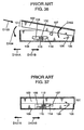
- Figs. 36 and 37 are each a side view showing a configuration of such a disk unit.
- Fig. 36 shows a disk-medium insertion hole opened in such a way that a disk medium (not shown) can be inserted or ejected.
- Fig. 37 shows the closed disk-medium insertion hole.
- reference numeral 106 denotes a unit body including a drive portion for making a recording and/or a reproduction for a disk medium; 101, a lid body covering the unit body 106; 102, a housing portion housing a disk medium added to the lid body 101; 105, a swing shaft for holding the lid body 101 on the unit body 106 in such a way that it can swing; 107 and 108, a hook portion and a slider for keeping the lid body 101 closed on the unit body 106, respectively; 112, a slider operation portion for moving the slider 108 in the direction of an arrow D101A; 114, a stopper added to the slider 108 and hooked by the hook portion 107 when the lid body 101 is closed; 115, a forcing spring for forcing the slider 108 in the direction of an arrow D101B; and 126, an opening spring for giving a force in the opening direction of an arrow D102.
- the user When a user conducts recording and/or reproduction for a disk medium in this disk unit, the user inserts a disk medium in the direction of an arrow D103 into the open lid body 101 of Fig. 36 . Then, the user closes the lid body 101 in the direction of an arrow D104 against the force of the opening spring 126 in the direction of the arrow D102.
- the hook portion 107 presses the stopper 114 against the force of the forcing spring 115 and moves it temporarily in the direction of the arrow D101A.
- the force of the forcing spring 115 moves it back in the direction of the arrow D101B and the hook portion 107 hooks and locks the stopper 114.
- the lid body 101 is kept closed as shown in Fig. 37 .
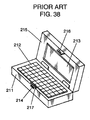
- Fig. 38 is a perspective view showing a configuration of such a portable terminal.
- Reference numeral 211 designates a unit body; 212, an operation panel united to the unit body 212 for operating the terminal; 215, a terminal lid supported so as to open and close on the unit body 211; 213, a display panel; 216 and 217, a hooking member and a hooked member for keeping and locking the lid 215 closed on the unit body 211, respectively; 214, an unhooking portion protruding from the unit body 211 and united with the hooked member 217.
- This terminal is provided with a built-in changeover switch (not shown) making a changeover when the lid 215 opens and closes. Thereby, the user can operate the display panel 213 and all the other functions when the lid 215 is open. In contrast, when the lid 215 is closed with respect to the unit body 211, this terminal is in a standby state or a power-off state where many functions are restricted including a display function of the display panel 213. This is because the terminal is portable thus requiring the saving of energy.
- a portable terminal has recently had more and more functions.
- it should desirably be provided with various interfaces and capable of conducting recording or reproduction for diverse media.
- a disk unit as a complex unit (not shown) can be considered which is a combination of the disk unit shown in Figs. 36 and 37 and the portable terminal shown in Fig. 38 .
- This complex unit is capable of conducting recording or reproduction for disk media using the operation panel 212 and displaying information on disk media, for example, on the display panel 213. It is also capable of inserting and ejecting a disk medium through a suitable operation for a portable terminal.
- Such a complex unit has the following problem, though it is easily operable.
- a user can move the slider operation portion 112 in the direction of the arrow D101A and eject a disk medium even while the unit is making a recording or a reproduction for the disk medium.
- the disk medium may be ejected while rotating and hit a member or the like around it accidentally thus damaging the disk medium itself. Further, its turning force can cause the disk medium to fly out.
- the disk medium is an optical disk
- a laser is employed for recording and reproduction.
- the lid body 101 may be opened while the laser is emitting a beam. This can cause the laser beam to irradiate the eyes of the user.
- US 2007/0019374 A1 relates to a disk drive media access system.
- a disk drive media access system opens a media access door to the interior of a disk drive sufficiently for ejection of disk media from the disk drive but insufficiently for manually engaging and removing disk media that is operationally positioned within the disk drive.
- the disk media is kept substantially laterally stationary during the opening of the media access door.
- the disk media is moved sufficiently for manually engaging the disk media for removing the disk media from the disk drive.
- a disk apparatus includes: a body unit including a disk drive for housing a disk-shaped information recording medium having an information recording surface and for recording and/or reproducing information; and a display unit including a display surface for displaying information, and closed and opened with respect to the body unit in such a way that the display surface is postured face down and up, in which: the body unit includes a disk insertion-and-ejection mechanism which is movable in a bottom direction of the body unit and inserts and ejects the information recording medium into and from the disk drive, and a lock mechanism locking the information recording medium housed in the body unit; and a locking state of the lock mechanism is maintained when the display unit is in the open state with respect to the body unit.
- a disk drive unit which is used in a disk apparatus including a body unit, and a display unit having a display surface for displaying information and closed and opened with respect to the body unit in such a way that the display surface is postured face down and up, includes: a disk drive for housing a disk-shaped information recording medium having an information recording surface and recording and/or reproducing information; and a disk insertion-and-ejection mechanism which: is disposed on a bottom-surface side of the body unit opposite to a surface thereof on which the display unit is disposed; is movable in a bottom direction of the body unit; and inserts and ejects the information recording medium into and from the disk drive, in which a hooking portion of the display unit interlocks with an opening operation of the display unit and hooks a hooked portion of the disk insertion-and-ejection mechanism to thereby prohibit the disk insertion-and-ejection mechanism from opening, and the hooking portion of the display unit interlocks with a closing operation of the display unit and unhooks the hooked portion of
- a disk-shaped information recording medium can be prevented from flying out accidentally while the apparatus is in operation.
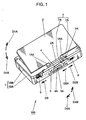
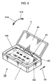
- Figs. 1 and 2 show the whole configuration and external appearance of the disk apparatus according to the first embodiment, each seen from a different angle.
- the disk apparatus 100 includes an apparatus body 1 as the body unit and a lid body 2 covering the apparatus body 1.
- the lid body 2 is provided at an edge thereof with a swing hinge portion 2A held on two swing supporting portions 1AA disposed in the apparatus body 1. This allows the lid body 2 to open and close in both directions of an arrow D1A and an arrow D1B.
- the lid body 2 is at a different angle to the apparatus body 1.
- a display 2B is attached to the lid body 2 as the display unit. It displays an image, including image contents, apparatus-operation information or the like.
- the display 2B is formed, for example, by a liquid-crystal panel or the like.
- a main-power switch 1SA is used for turning on or off the main power of the disk apparatus 100. A user can turn on the main power by moving it in the direction of an arrow D5. Further, an operation-switch group 1SB including each switch for a user operating the disk apparatus 100 is arranged in the middle of the top surface of the apparatus body 1.
- a power cut-off switch 1SC is used for cutting off all power supplies.
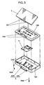
- the apparatus body 1 is provided with a drive-portion cover 3 covering the disk drive portion 11.
- the user puts in and takes out the disk medium 31 by swinging the drive-portion cover 3 so as to open and close it.
- two cover shafts 3L and 3R are united with the drive-portion cover 3 and fitted into two body bearings 1BAL and 1BAR, respectively.
- the drive-portion cover 3 is held so as to swing in the directions of an arrow D4A and an arrow D4B.
- the drive-portion cover 3 and the like configures the disk insertion-and-ejection mechanism which is movable in a bottom direction of the apparatus body 1 and inserts and ejects the disk medium 31 into and from the disk drive portion 11.
- Fig. 6 shows a schematic configuration of the disk drive portion 11.
- the disk drive portion 11 includes a disk motor 11M, a pickup 11P, a drive-portion base 11B, guide shafts 11GL and 11GR, and vibration-isolation dampers 11S.
- the disk motor 11M rotates the disk medium 31 placed and fixed there.
- the pickup 11P is formed by a pickup base portion 11PB and a lens portion 11PL mounted on there. It is guided and held by the two guide shafts 11GL and 11GR in such a way that it can move in the directions of an arrow D11 parallel to a specific radius direction of the disk medium 31 placed on the disk motor 11M. From the lens portion 11PL, a laser beam of a semiconductor laser or the like irradiates the disk medium 31 as the optical disk.
- the pickup 11P conduct recording and/or reproduction on an information recording surface of the disk medium 31.
- the drive-portion base 11B holds the disk motor 11M and the guide shafts 11GL and 11GR.
- each vibration-isolation damper 11S It is attached to the apparatus body 1 via each vibration-isolation damper 11S in four places in such a way that it can restrain a vibration from the outside or prevent the leakage of a vibration of the apparatus 100 caused by a disk rotation.
- a well-known drive mechanism can be employed for a drive mechanism sending the pickup 11P in the directions of the arrow D11. Thus, its figure and description are omitted.
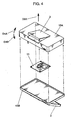
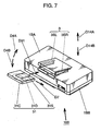
- Fig. 7 is a perspective view showing how the above described disk insertion-and-ejection mechanism inserts the disk medium 31 into the disk apparatus 100.
- a disk cartridge 31C housing a disk 31D is used as the disk medium 31.
- the user When using the disk medium 31, the user inserts the disk medium 31 in the direction of an arrow D31 into the disk apparatus 100 with the drive-portion cover 3 kept open in the direction of the arrow D4A.
- the drive-portion cover 3 includes cartridge guides 3SL and 3SR united thereto, and the disk medium 31 is guided and inserted along these cartridge guides 3SL and 3SR.
- the disk cartridge 31C is provided with a cartridge shutter 31S opening and closing an opening for exposing an information recording surface of the disk 31D.
- a shutter opening mechanism (not shown) moves the cartridge shutter 31S in the direction of an arrow D7. This opens the opening to thereby expose the information recording surface of the disk 31D, so that a recording and a reproduction can be made.
- Figs. 8 and 9 show a main part inside of the apparatus body 1 on the side of the body lower case 1BA.
- Fig. 8 shows the whole and Fig. 9 shows the details thereof.
- reference numeral 4 designates a lock slider for keeping the drive-portion cover 3 closed in the body lower case 1BA.
- the lock slider 4 is held on the body lower case 1BA in such a way that it can slide in the directions of an arrow D2A and an arrow D2B. It is always given a force in the direction of the arrow D2B by a slider spring 6.
- the lock slider 4 is provided with a slide knob 5 connected thereto. This slide knob 5 is used for sliding it in the direction of the arrow D2A from outside of the body lower case 1BA.
- the lock slider 4 is united at a middle lower part thereof with a lock hook 4A hooking a cover hook 3A united with the drive-portion cover 3.
- the lock hook 4A and the cover hook 3A prevent the drive-portion cover 3 from swinging in the direction of the arrow D4A (see Fig. 1 or another).
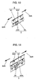
- Figs. 10 and 11 show how to hook the lock hook 4A on the cover hook 3A of Fig. 8 , after and before the hooking, respectively.
- the lock hook 4A and the cover hook 3A are formed with a lock-hook taper surface 4AA and a cover-hook taper surface 3AA, respectively.
- the lock slider 4 slides in the direction of the arrow D2A against the force of the slider spring 6.
- the lock hook 4A unhooks the cover hook 3A, allowing the drive-portion cover 3 to open at this time in the direction of the arrow D4A of Fig. 7 .
- the drive-portion cover 3 may also be opened by utilizing the weight of the drive-portion cover 3 itself, or using a forcing member such as a coil spring as assistance.
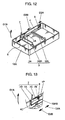
- reference numeral 7 denotes an ejection stopper preventing the lock slider 4 from sliding in the direction of the arrow D2A.
- the ejection stopper 7 is held so as to pivot by inserting an ejection-stopper shaft 1BAS provided in the body lower case 1BA into an ejection-stopper pivot hole 7B.
- An ejection-stopper spring 8 is attached to the ejection-stopper shaft 1BAS as a support shaft thereof.
- One end of the ejection-stopper spring 8 is hitched to a fixation-side spring hitch 1P provided in the body lower case 1BA.
- the other end thereof is hitched to a pivot-side spring hitch 7C provided in the ejection stopper 7.
- the ejection-stopper spring 8 is a torsion coil spring thus forcing the ejection stopper 7 to pivot in the direction of an arrow D7A shown in Figs. 8, 9 , 12 and 13 .
- an ejection-stopper press portion 7A provided in the ejection stopper 7 penetrates a through hole 1H provided in the body upper case 1BB. Hence, it juts out from the surface of the body upper case 1BB.
- the lid body 2 does not press the ejection-stopper press portion 7A when the lid body 2 is not largely open in the direction of the arrow D1A.
- the lock slider 4 is movable in the direction of the arrow D2A.
- the user can move the lock slider 4 in the direction of the arrow D2A and open the drive-portion cover 3. This makes it possible to insert and eject the disk cartridge 31C freely.
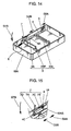
- the user can watch the display 2B and manipulate the main-power switch 1SA, the operation-switch group 1SB or the like. If the lid body 2 opens in the direction of the arrow D1A and comes into this state, a lower edge part of the lid body 2 presses in the ejection-stopper press portion 7A. As shown in Figs. 14 and 15 , the ejection stopper 7 pivots in the direction of an arrow D7B. At this time, a lock hook-stopping portion 4C provided in the lock slider 4 comes into contact with a stopper hook-stopping portion 7D provided in the ejection stopper 7.
- the stopper hook-stopping portion 7D hinders the lock hook-stopping portion 4C from moving so that the lock slider 4 cannot move in the direction of the arrow D2A.
- the disk medium 31 cannot be taken out if the disk drive portion 11 starts to operate with the disk medium 31 kept inserted.
- the disk 31D rotates and a laser beam irradiates the disk medium 31 from the lens portion 11PL in the disk drive portion 11. If the user takes out the disk medium 31 during this operation, the disk 31D may fly out at the user, or a laser beam from a semiconductor laser can enter the eyes of the user.
- the user cannot take out the disk medium 31 with the lid body 2 kept opened with respect to the apparatus body 1, in other words, with the disk drive portion 11 in operation. This helps prevent the above described problem.
- the user cannot operate the main-power switch 1SA and the operation-switch group 1SB until the lid body 2 is opened with respect to the apparatus body 1 so that the disk medium 31 cannot be ejected. This is helpful in preventing the disk 31D from rotating accidentally and a semiconductor laser from emitting a beam outside before the disk medium 31 is securely inserted.
- the user may swing and close the lid body 2 in the direction of the arrow D1B by mistake with the main-power switch 1SA remaining "on".
- this swing of the lid body 2 allows the cut-off protrusion 2C to press and operate the power cut-off switch 1SC. This helps prevent the drive-portion cover 3 from opening while the disk 31D is being rotated or a semiconductor laser is emitting a beam.
- the lock slider 4 keeps the drive-portion cover 3 in a state where the disk medium 31 cannot be inserted and ejected. Hence, the disk medium 31 is not supposed to be taken out while the disk drive portion 11 is making a recording or a reproduction for the disk medium 31. This makes it possible to prevent the disk 31D from flying out or being exposed while rotating. As a result, the user can be protected from the rotating disk 31D, a beam from a semiconductor laser or the like.
- the drive-portion cover 3 needs to be placed in a bottom part of the apparatus body 1 and opened and closed on the opposite side to the display 2B. In this case, in an ordinary state where the display 2B is above the apparatus body 1, if the drive-portion cover 3 opens by accident, the disk medium 31 may fly out instantly because of its.
- a locking operation of the lock slider 4 interlocks with a relative movement of the lid body 2 with respect to the apparatus body 1.
- the locking state can be automatically maintained as the lid body 2 opens. This makes it possible to evade the above problem using such a simple configuration.
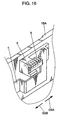
- Fig. 16 shows the details of the slide knob 5 and its vicinity in Figs. 1 , 8 , 9 and 12 to 15 .
- reference numeral 9 designates an overload prevention spring as a compression spring.
- the overload prevention spring 9 forces the slide knob 5 in the direction of the arrow D2B against the lock slider 4. According to this configuration, in the state where the ejection stopper 7 hinders the lock slider 4 from sliding in the direction of the arrow D2A, even if the user slides the slide knob 5 further in the direction of the arrow D2A, the force by which the user is handling the slide knob 5 is absorbed.
- a spring force of the overload prevention spring 9 is set to F9; a spring force of the slider spring 6, F6; a maximum force for the user handling the slide knob 5, FO; and a minimum breaking strength of any member of the slide knob 5, the lock slider 4 and the ejection-stopper shaft 1BAS when the user slides the slide knob 5 in the direction of the arrow D2A with the slide knob 5 and the lock slider 4 directly connected without the overload prevention spring 9, FM.
- the lock slider 4 slides in the direction of the arrow D2A without being hindered by the ejection stopper 7, it needs to be slid against the spring force of the slider spring 6. In other words, (expression 1) needs to be satisfied.
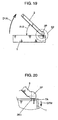
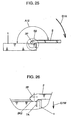
- Figs. 17 to 26 show an example of a configuration for realizing the above function and are each a side view of the disk apparatus 100 according to this embodiment.
- Figs. 18 , 20 , 22 , 24 and 26 are each an enlarged view showing the details of a part S2 shown in Figs. 17 , 19 , 21 , 23 and 25 .
- the second press surface 2K2 is a curved surface united to an edge part of the lid body 2 in such a way that the distance from the swing center of the lid body 2 to the radius directions becomes constant as the lid body 2 opens further.
- the first press surface 2K1 interlocks with an opening movement of the lid body 2, comes into contact with the top surface of the ejection-stopper press portion 7A and presses the ejection-stopper press portion 7A into the apparatus body 1.
- the second press surface 2K2 comes into contact with the top surface of the ejection-stopper press portion 7A and presses the ejection-stopper press portion 7A into the apparatus body 1. Then, this pressing state is maintained.
- Figs. 17 and 18 show that the lid body 2 is kept closed at the apparatus body 1 (the lid body 2 lies at an angle of zero degrees to the apparatus body 1).
- the first press surface 2K1 of the stopper pressing portion 2P is in contact with the top surface of the ejection-stopper press portion 7A
- the first press surface 2K1 is designed not to press the ejection-stopper press portion 7A.
- the ejection-stopper press portion 7A remains unmoved in the direction of the arrow D7W.
- the ejection-stopper spring 8 gives a force to the ejection-stopper press portion 7A in the direction of an arrow D7Y.
- the lock slider 4 can slide in the directions of the arrows D2A and D2B thus making it possible to open the drive-portion cover 3.
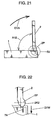
- Figs. 21 and 22 show that the lid body 2 opens further in the direction of the arrow D1A from the apparatus body 1 and stands at the angle A12 of 90 degrees to the apparatus body 1.
- the user can operate the main-power switch 1SA and the operation-switch group 1SB as well as view the display 2B without any particular trouble in the disk apparatus 100.
- the second press surface 2K2 of the stopper pressing portion 2P keeps the ejection-stopper press portion 7A pressed in the direction of the arrow D7W. This still hinders the lock slider 4 from sliding in the direction of the arrow D2A.
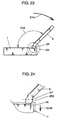
- Figs. 23 and 24 show that the lid body 2 opens still further in the direction of the arrow D1A from the apparatus body 1 and swings up to the angle A12 of 135 degrees to the apparatus body 1.
- the user can easily operate the main-power switch 1SA and the operation-switch group 1SB as well as view the display 2B in the disk apparatus 100 according to this embodiment.
- the second press surface 2K2 keeps the ejection-stopper press portion 7A pressed in the direction of the arrow D7W. This continues hindering the lock slider 4 from sliding in the direction of the arrow D2A.
- the ejection-stopper press portion 7A is forced in the direction of the arrow D7W to thereby hinder the lock slider 4 from sliding in the direction of the arrow D2A. This helps prevent the drive-portion cover 3 from opening.
- the display 2B as the display surface of the lid body 2 should preferably be opened face up in such a way that the lid body 2 lies at an angle of 45 or more degrees to the apparatus body 1. More desirably, it should be 90 degrees or wider, and far more desirably, 135 degrees or above.
- the user can operate the main-power switch 1SA and the operation-switch group 1SB as well as view the display 2B in the disk apparatus 100.
- the user is highly likely to be making a recording and a reproduction for the disk medium 31 in the disk drive portion 11. In this situation, it is highly expected that the disk medium 31 needs to be prevented from flying out or from being exposed while rotating when the user makes an error in operation.
- such an apparatus is provided with a type of disk housed in a cartridge as the medium.
- the drive-portion cover 3 may also be further opened in such a way that the disk drive portion 11 is largely exposed. In that case, even if an apparatus is provided with a disk placed as a single unit on the disk motor 11M, the same advantages can be obtained.
- a helical extension spring is used as the slider spring 6.
- a torsion coil spring or another means is employed, the same advantages can be obtained, as long as the lock slider 4 can be given a force in the direction of the arrow D2B.
- a torsion coil spring is used as the ejection-stopper spring 8.
- a helical extension spring or another means is employed, the same advantages can be obtained, as long as the ejection stopper 7 can be given a force in the direction of the arrow D7A.
- a compression coil spring is used as the overload prevention spring 9.
- a helical extension spring or another means is employed, the same advantages can be obtained, as long as the lock slider 4 can be given a force in the direction of the arrow D2A against the slide knob 5.
- the configuration for swinging the drive-portion cover 3 in the direction of the arrow D4A is used as the configuration for opening it.
- a disk medium may move and open in parallel to the direction of an arrow D14A shown in Fig. 7 and move and close in parallel to the direction of an arrow D14B after a disk medium is inserted.
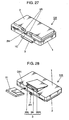
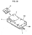
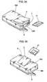
- Figs. 27 and 28 each show an external appearance of a disk apparatus 101 provided with a blocking hook 2H according to this embodiment.
- Figs. 29 and 30 each show a relative positional relationship in exterior view between the blocking hook 2H and a fixation hook 3H.
- Fig. 29 shows the entire apparatus seen at a different angle from Fig. 27 .
- Fig. 31 shows the lid body 2 opened from the state of Fig. 29.
- Figs. 30 and 32 are each a schematic sectional view on a plane P1 of the whole apparatus shown in Figs. 29 and 31 , respectively.
- the disk medium 31 is inserted in the direction of the arrow D31 along the cartridge guides 3SL and 3SR.
- the disk apparatus 101 according to this embodiment can also be used in the same way as the first embodiment.
- the disk apparatus 101 according to this embodiment is different from the first embodiment as follows.
- the lid body 2 is designed to directly prevent the drive-portion cover 3 from opening when the lid body 2 is kept open.
- the blocking hook 2H prevents the drive-portion cover 3 from opening when the lid body 2 is kept open.
- the fixation hook 3H corresponds to the hooked portion disposed in the drive-portion cover 3 and is hooked by the blocking hook 2H as the hooking portion.
- the blocking hook 2H protrudes from a middle part of the swing hinge portion 2A of the lid body 2. It comes into a passage hole 1C formed in the apparatus body 1 when the lid body 2 opens in the direction of the arrow D1A.
- the fixation hook 3H is united with a bridge part between the two cartridge guides 3SL and 3SR of the drive-portion cover 3.
- the fixation hook 3H is not under restraint when the lid body 2 is kept closed, so that the drive-portion cover 3 can be freely opened in the direction of the arrow D4A.
- the blocking hook 2H hooks the fixation hook 3H to thereby prevent the drive-portion cover 3 from opening.
- the drive-portion cover 3 is hindered from opening while the lid body 2 is open, in other words, while the disk apparatus 101 is in operation. Therefore, similarly to the first embodiment, the disk medium 31 is not supposed to be accidentally taken out while a reproduction or a recording is being made for the disk 31D. Consequently, the rotating disk 31D can be prevented from flying out at the user, or a laser beam from a semiconductor laser can be kept from entering the eyes of the user. This helps keep the user safer.
- the swing center axis on which the drive-portion cover 3 opens and closes with respect to the apparatus body 1 is parallel to the swing center axis on which the lid body 2 opens and closes.
- the swing directions in which the drive-portion cover 3 and the lid body 2 open are both clockwise around the swing centers and have a front and back side relation to each other, for example, if the disk apparatus 100 is seen from the right-hand side in the state of Fig. 7 .
- the present invention is not limited to this configuration.
- a disk apparatus includes: a body unit including a disk drive for housing a disk-shaped information recording medium having an information recording surface and for recording and/or reproducing information; and a display unit including a display surface for displaying information, and closed and opened with respect to the body unit in such a way that the display surface is postured face down and up, in which: the body unit includes a disk insertion-and-ejection mechanism which is movable in a bottom direction of the body unit and inserts and ejects the information recording medium into and from the disk drive, and a lock mechanism locking the information recording medium housed in the body unit; and a locking state of the lock mechanism is maintained when the display unit is in the open state with respect to the body unit.
- the lock mechanism when the display unit is opened with respect to the body unit, the lock mechanism keeps the disk insertion-and-ejection mechanism in a state where the disk-shaped information recording medium cannot be inserted and ejected. Hence, the information recording medium is not supposed to be taken out while the disk drive is making a recording or a reproduction for the information recording medium. This makes it possible to prevent the information recording medium from fly ing out or being exposed while rotating. Besides, an operation of the lock mechanism interlocks with a relative movement of the display unit with respect to the body unit. Thus, using a simple configuration, the locking state can be automatically maintained as the display unit opens.
- the locking state of the lock mechanism is released only when the display unit is in the closed state with respect to the body unit. Therefore, the user can take out the information recording medium only when the user is not using this disk apparatus. This makes it possible to certainly prevent the information recording medium from flying out or being exposed while rotating.
- the disk insertion-and-ejection mechanism is disposed on a bottom-surface side of the body unit. This makes it easier for the information recording medium to fly out because of its weight from the disk insertion-and-ejection mechanism. In this state, however, the information recording medium can be prevented from flying out or being exposed while rotating.
- the lock mechanism include: a hooking portion disposed in a slider held so as to slide on the body unit; a hooked portion disposed in the disk insertion-and-ejection mechanism and hooked on the hooking portion; and a slider spring giving a force to the slider in parallel to a direction where the slider slides and in a direction where the hooking portion hooks the hooked portion.
- the body unit further include a lock retention member stopping the slider from moving in a direction where the hooking portion unhooks the hooked portion, and an unlocking spring changing the lock retention member from a stop state where the slider is stopped from moving to a nonstop state where the slider is not stopped from moving in such a way that the locking state of the lock mechanism is released; and when the display unit changes from the closed state to the open state, the lock retention member interlock with an opening operation of the display unit and change from the nonstop state to the stop state, and when the display unit changes from the open state to the closed state, the unlocking spring allow the lock retention member to change from the stop state to the nonstop state.
- the lock retention member hooks and stops a part of the slider. Therefore, using a simple configuration, the disk insertion-and-ejection mechanism can be kept locked firmly on the body unit.
- the body unit further include an operation member having a manual operation portion exposed outside of the body unit, and a connection spring connecting the operation member to the slider between the slider and the operation member; and the connection spring have a greater force than the slider spring.
- the lock retention member include a protrusion portion protruding from the surface of the body unit on the side where the display unit is held so as to swing, and a hook-stopping portion stopping the slider from moving by coming into contact with the slider; and an edge of the display unit interlock with an opening operation of the display unit by pushing the protrusion portion into the body unit to thereby bring the hook-stopping portion into contact with the slider and stop the slider from moving, and the protrusion portion interlock with a closing operation of the display unit by protruding from the surface of the body unit to thereby separate the hook-stopping portion from the slider and permit the slider to move.
- the information recording medium be an optical disk; and the disk drive apply a laser beam to the optical disk when a recording and/or a reproduction is made for the optical disk.
- the body unit further include a power cut-off switch for cutting off all power supplies; and the power cut-off switch interlock with a closing operation of the display unit and turn on to thereby cut off all power supplies.
- the disk insertion-and-ejection mechanism when the display unit is kept open because the user uses the disk apparatus, the disk insertion-and-ejection mechanism can be prohibited from opening.
- the disk insertion-and-ejection mechanism when the display unit is kept closed because the user exchanges the information recording medium, the disk insertion-and-ejection mechanism can be permitted to open. Therefore, using a simple configuration and without deteriorating the operability by the user, the information recording medium can be certainly prevented from flying out or being exposed while rotating because the user operates it by mistake.
- the disk apparatus according to the present invention is capable of preventing the disk-shaped information recording medium from flying out accidentally while the apparatus is in operation. Therefore, it is suitable for a disk apparatus including a disk drive capable of recording and/or reproducing information using a disk-shaped information recording medium. Particularly, it is suitable for a potable apparatus usable for a disk-shaped information recording medium.
Landscapes
- Feeding And Guiding Record Carriers (AREA)
Claims (10)
- Platten- bzw. Datenträgervorrichtung, aufweisend:eine Körpereinheit (1), die ein Platten- bzw. Datenträgerlaufwerk (11) enthält, und zwar zum Unterbringen eines plattenförmigen Informationsaufzeichnungsmediums, das eine Informationsaufzeichnungsoberfläche hat, und zum Aufzeichnen und/oder Reproduzieren von Informationen; undeine Anzeigeeinheit (2B), die eine Anzeigeoberfläche zum Anzeigen von Informationen enthält, und geschlossen und geöffnet bezüglich zu der Körpereinheit (1) in einer derartigen Art und Weise ist, dass die Anzeigeoberfläche mit der Vorderseite nach unten und nach oben arrangiert ist, wobei die Anzeigeeinheit (2B) so gehalten wird, um auf der Körpereinheit (1) zu schwenken,wobei:die Körpereinheit (1) ferner einen Platten- bzw. Datenträgereinführungs- und -ausbringungsmechanismus (3), welcher auf einer Schwenkzentrumsachse auf einer Boden- bzw. Unterteiloberflächenseite der Körpereinheit (1) bewegbar ist, und zwar für die Einführung und Ausbringung des Informationsaufzeichnungsmediums in und aus dem Platten- bzw. Datenträgerlaufwerk (11), und einen Einschließ- bzw. Sicherungsmechanismus (4) zum Einschließen bzw. Sichern des Informationsaufzeichnungsmediums enthält, das in der Körpereinheit (1) untergebracht ist;dadurch gekennzeichnet, dasswenn die Anzeigeeinheit (2B) in dem offenen Zustand bezüglich der Körpereinheit (1) ist, sie mit dem Einschließ- bzw. Sicherungsmechanismus in einer derartigen Weise in Eingriff ist, dass der Einschließ- bzw. Sicherungsmechanismus nicht aus seinem Verriegelungszustand zu dem Entriegelungszustand bewegt werden kann; undder Verriegelungszustand des Einschließ- bzw. Sicherungsmechanismus nur freigegeben wird, wenn die Anzeigeeinheit (2B) in dem geschlossenen Zustand bezüglich der Körpereinheit (1) ist.
- Platten- bzw. Datenträgervorrichtung gemäß Anspruch 1, wobei:der Platten- bzw. Datenträgereinführungs- und -ausbringungsmechanismus (3) auf einer untersten bzw. Bodenoberflächenseite der Körpereinheit (1) entgegengesetzt zu einer Oberfläche davon angeordnet ist, auf welcher die Anzeigeeinheit (2B) angeordnet ist, und so gehalten ist, um in der Bodenrichtung auf der Körpereinheit (1) zu schwenken.
- Platten- bzw. Datenträgervorrichtung gemäß Anspruch 1, wobei der Einschließ- bzw. Sicherungsmechanismus enthält: einen Haken- bzw. Rastabschnitt (2H), der in einem Gleitstück bzw. Schieber (4) angeordnet ist, das bzw. der so gehalten ist, um auf der Körpereinheit (1) zu gleiten; einen hakenförmigen bzw. rastenförmigen Abschnitt (3H), der in dem Platten- bzw. Datenträgereinführungs- und -ausbringungsmechanismus (3) angeordnet ist und auf dem Haken- bzw. Rastabschnitt (2H) eingehakt bzw. eingerastet ist; und eine Gleitstück- bzw. Schieberfeder, die eine Kraft an das Gleitstück bzw. den Schieber abgibt bzw. überträgt, und zwar parallel zu einer Richtung, wo das Gleitstück bzw. der Schieber (4) gleitet und in einer Richtung, wo der Haken- bzw. Rastabschnitt (2H) den hakenförmigen bzw. rastenförmigen Abschnitt (3H) anhakt bzw. einrastet.
- Platten- bzw. Datenträgervorrichtung gemäß Anspruch 1, wobei:die Körpereinheit (1) ferner ein Einschließ- bzw. Sicherungsbeibehaltungsglied, das das Gleitstück bzw. den Schieber (4) am Bewegen in eine Richtung hindert bzw. stoppt, wo der Haken- bzw. Rastabschnitt (2H) den hakenförmigen bzw. rastenförmigen Abschnitt (3H) loshakt bzw. ausrastet, und eine Loshakungs- bzw. Ausrastungsfeder enthält, die das Einschließ- bzw. Sicherungsbeibehaltungsglied von einem Hinderungs- bzw. Stoppzustand, wo das Gleitstück bzw. der Schieber (4) am Bewegen gehindert bzw. gestoppt wird, zu einem durchgehenden bzw. nicht gestoppten Zustand schaltet bzw. ändert, wo das Gleitstück bzw. der Schieber (4) nicht am Bewegen gehindert bzw. gestoppt wird, und zwar in einer derartigen Art und Weise, dass der Verriegelungszustand des Einschließ- bzw. Sicherungsmechanismus freigegeben wird; undwenn sich die Anzeigeeinheit (2B) von dem geschlossenen Zustand zu dem offenen Zustand ändert, das Einschließ- bzw. Sicherungsbeibehaltungsglied mit einem Öffnungsvorgang der Anzeigeeinheit (2B) kuppelt und sich von dem durchgehenden bzw. nicht gestoppten Zustand zu dem Hinderungs- bzw. Stoppzustand ändert, und wenn sich die Anzeigeeinheit (2B) von dem offenen Zustand zu dem geschlossenen Zustand ändert, ermöglicht es die Entriegelungsfeder dem Einschließ- bzw. Sicherungsbeibehaltungsglied, sich von dem Hinderungs- bzw. Stoppzustand zu dem durchgehenden bzw. nicht gestoppten Zustand zu ändern.
- Platten- bzw. Datenträgervorrichtung gemäß Anspruch 3, wobei:die Körpereinheit (1) ferner ein Betätigungsglied, das einen manuellen Betätigungsabschnitt hat, und zwar freiliegend bzw. außerhalb der Körpereinheit (1), und eine Verbindungsfeder enthält, die das Betätigungsglied mit dem Gleitstück bzw. Schieber (4) zwischen dem Gleitstück bzw. Schieber (4) und dem Betätigungsglied verbindet; und wobei die Verbindungsfeder eine größere Kraft bzw. Stärke als die Gleitstück- bzw. Schieberfeder hat.
- Platten- bzw. Datenträgervorrichtung gemäß Anspruch 3, wobei:das Einschließ- bzw. Sicherungsbeibehaltungslied einen Vorsprungabschnitt, der von der Oberfläche der Körpereinheit (1) auf der Seite vorspringt, wo die Anzeigeeinheit (2B) so gehalten wird, um zu schwenken, und einen Haken- bzw. Rastverhinderungsabschnitt enthält, der das Gleitstück bzw. den Schieber (4) vom Bewegen hindert, und zwar durch das in Kontakt kommen mit dem Gleitstück bzw. Schieber (4); undein Rand bzw. eine Kante der Anzeigeeinheit (2B) kuppelt mit einem Öffnungsvorgang der Anzeigeeinheit (2B) durch Schieben bzw. Drängen des Vorsprungabschnittes in die Körpereinheit (1), um dadurch den Einschließ- bzw. Sicherungshinderungsabschnitt in Kontakt mit dem Gleitstück bzw. Schieber (4) zu bringen und das Gleitstück bzw. den Schieber (4) am Bewegen zu hindern bzw. zu stoppen, und der Vorsprungsabschnitt kuppelt mit einem Schließvorgang der Anzeigeeinheit (2B) durch Vorspringen von der Oberfläche der Körpereinheit (1), um dadurch den Einschließ- bzw. Sicherungshinderungsabschnitt von dem Gleitstück bzw. Schieber (4) zu separieren bzw. abzusondern und es dem Gleitstück bzw. Schieber zu ermöglichen, sich zu bewegen.
- Platten- bzw. Datenträgervorrichtung gemäß Anspruch 1, wobei:der Einschließ- bzw. Sicherungsmechanismus einen Haken- bzw. Rastabschnitt (2H), der in der Anzeigeeinheit (2B) angeordnet ist, und einen hakenförmigen bzw. rastenförmigen Abschnitt (3H) enthält, der in dem Platten- bzw. Datenträgereinführungs- und -ausbringungsmechanismus (3) angeordnet ist und auf dem Haken- bzw. Rastabschnitt (2H) der Anzeigeeinheit (2B) eingehakt bzw. eingerastet ist; undwobei der Haken- bzw. Rastabschnitt (2H) der Anzeigeeinheit (2B) mit einem Öffnungsvorgang der Anzeigeeinheit (2B) kuppelt und den hakenförmigen bzw. rastenförmigen Abschnitt (3H) des Platten- bzw. Datenträgereinführungs- und -ausbringungmechanismus (3) einhakt bzw. einrastet, um dadurch den Platten- bzw. Datenträgereinführungs- und -ausbringungsmechanismus (3) am Öffnen zu hindern, und wobei der Haken- bzw. Rastabschnitt (2H) der Anzeigeeinheit (2B) mit einem Schließvorgang der Anzeigeeinheit (2B) kuppelt und den hakenförmigen bzw. rastenförmigen Abschnitt (3H) des Platten- bzw. Datenträgereinführungs- und -ausbringungsmechanismus (3) loshakt bzw. ausrastet, um dadurch dem Platten- bzw. Datenträgereinführungs- und -ausbringungsmechanismus (3) zu gestatten, zu öffnen.
- Platten- bzw. Datenträgervorrichtung gemäß Anspruch 1, wobei:das Informationsaufzeichnungsmedium eine optische Platte ist; unddas Platten- bzw. Datenträgerlaufwerk (11) einen Laserstrahl bzw. Laserstrahlbündel auf die optische Platte anwendet, wenn eine Aufzeichnung und/oder eine Reproduktion für die optische Platte bewirkt wird.
- Platten- bzw. Datenträgervorrichtung gemäß Anspruch 1, wobei:die Körpereinheit (1) ferner einen Hauptschalter (1SA) enthält, der auf einer Oberfläche davon auf der Seite der Anzeigeeinheit (2B) angeordnet ist; undwobei die Anzeigeeinheit (2B) den Hauptschalter (1SA) in dem geschlossenen Zustand verdeckt, und zwar in einer derartigen Art und Weise, dass der Hauptschalter (1SA) durch einen Anwender nicht betätigbar ist.
- Platten- bzw. Datenträgervorrichtung gemäß Anspruch 1, wobei:die Körpereinheit (1) ferner einen Stromsperrenschalter (1SC) enthält, und zwar zum Abschalten von allen Strom- bzw. Energieversorgungen; undwobei der Stromsperrenschalter (1 SC) mit einem Schließvorgang der Anzeigeeinheit (2B) kuppelt und Kontakt macht, um dadurch alle Strom- bzw. Energieversorgungen abzuschalten.
Applications Claiming Priority (1)
| Application Number | Priority Date | Filing Date | Title |
|---|---|---|---|
| JP2007123187 | 2007-05-08 |
Publications (3)
| Publication Number | Publication Date |
|---|---|
| EP1990802A2 EP1990802A2 (de) | 2008-11-12 |
| EP1990802A3 EP1990802A3 (de) | 2010-10-20 |
| EP1990802B1 true EP1990802B1 (de) | 2012-07-04 |
Family
ID=39495741
Family Applications (1)
| Application Number | Title | Priority Date | Filing Date |
|---|---|---|---|
| EP08155878A Not-in-force EP1990802B1 (de) | 2007-05-08 | 2008-05-08 | Plattenapparatus und Laufwerk |
Country Status (3)
| Country | Link |
|---|---|
| US (1) | US8181192B2 (de) |
| EP (1) | EP1990802B1 (de) |
| JP (1) | JP4954937B2 (de) |
Families Citing this family (4)
| Publication number | Priority date | Publication date | Assignee | Title |
|---|---|---|---|---|
| US9836084B2 (en) * | 2014-03-28 | 2017-12-05 | Intel Corporation | Inferred undocking for hybrid tablet computer |
| NL2023857B1 (en) * | 2019-09-19 | 2021-05-25 | Microsoft Technology Licensing Llc | Systems and methods for dynamically adjusting opening force |
| WO2023122159A2 (en) * | 2021-12-22 | 2023-06-29 | Invue Security Products Inc. | Data center security systems and devices |
| US11849561B2 (en) | 2021-12-22 | 2023-12-19 | In Vue Security Products Inc. | Data center security systems and devices |
Family Cites Families (14)
| Publication number | Priority date | Publication date | Assignee | Title |
|---|---|---|---|---|
| JPS57162148A (en) * | 1981-03-30 | 1982-10-05 | Sony Corp | Rotating recording medium reproducer |
| US5323291A (en) * | 1992-10-15 | 1994-06-21 | Apple Computer, Inc. | Portable computer and docking station having an electromechanical docking/undocking mechanism and a plurality of cooperatively interacting failsafe mechanisms |
| JPH08235718A (ja) | 1995-02-27 | 1996-09-13 | Nippon Columbia Co Ltd | 記録媒体記録再生機及びイジェクト機構 |
| JPH1049254A (ja) | 1996-08-06 | 1998-02-20 | Nec Data Terminal Ltd | 携帯端末装置 |
| KR100422500B1 (ko) * | 1997-03-25 | 2004-06-26 | 삼성전자주식회사 | 전원 제어 모드 변환부를 가지는 휴대용 컴퓨터 |
| JPH11232836A (ja) * | 1998-02-12 | 1999-08-27 | Toshiba Corp | 多層情報層を有する情報記憶媒体及び多目的情報処理装置 |
| JP2002288974A (ja) * | 2001-03-22 | 2002-10-04 | Sony Corp | 電子機器 |
| KR100762391B1 (ko) * | 2001-07-10 | 2007-10-02 | 엘지전자 주식회사 | 휴대형 디스크 재생장치 |
| JP4119762B2 (ja) * | 2003-01-31 | 2008-07-16 | 富士フイルム株式会社 | 記録メデイア保護機構 |
| CN2706834Y (zh) * | 2004-05-28 | 2005-06-29 | 鸿富锦精密工业(深圳)有限公司 | 光盘播放器顶盖启闭装置 |
| CN2745176Y (zh) * | 2004-09-08 | 2005-12-07 | 鸿富锦精密工业(深圳)有限公司 | 光盘播放器 |
| US7574715B2 (en) * | 2005-07-20 | 2009-08-11 | Apple Inc. | Disk drive media access system |
| JP5032762B2 (ja) | 2005-10-31 | 2012-09-26 | キヤノン株式会社 | 電子機器 |
| TWI301338B (en) | 2006-08-30 | 2008-09-21 | Asustek Comp Inc | Electrionic apparatus with rotatable cover |
-
2008
- 2008-04-24 JP JP2008113728A patent/JP4954937B2/ja not_active Expired - Fee Related
- 2008-05-08 US US12/117,566 patent/US8181192B2/en not_active Expired - Fee Related
- 2008-05-08 EP EP08155878A patent/EP1990802B1/de not_active Not-in-force
Also Published As
| Publication number | Publication date |
|---|---|
| EP1990802A2 (de) | 2008-11-12 |
| EP1990802A3 (de) | 2010-10-20 |
| US20080282276A1 (en) | 2008-11-13 |
| JP4954937B2 (ja) | 2012-06-20 |
| JP2008305534A (ja) | 2008-12-18 |
| US8181192B2 (en) | 2012-05-15 |
Similar Documents
| Publication | Publication Date | Title |
|---|---|---|
| EP1990802B1 (de) | Plattenapparatus und Laufwerk | |
| EP1443513B1 (de) | Kassette als behälter für ein aufzeichnungsmedium | |
| KR101059493B1 (ko) | 디스크 카트리지용 셔터 부재, 디스크 카트리지 및 디스크 기록 또는 재생 장치 | |
| EP1622155B1 (de) | Türverriegelungseinheit und Platteninformationsaufzeichnungs/-wiedergabemethode und -vorrichtung, die dergleichen verwendet | |
| JP4706169B2 (ja) | ディスクカートリッジ | |
| JP4081885B2 (ja) | 磁気ヘッド装置 | |
| JP3525474B2 (ja) | ディスクカートリッジ駆動装置 | |
| JP4221786B2 (ja) | ホルダ装置を用いたディスク記録及び/又は再生装置 | |
| JP4250789B2 (ja) | 磁気ヘッドの昇降制御装置 | |
| JP3002465B2 (ja) | ディスクカ―トリッジ | |
| JP2001143359A (ja) | ディスク駆動装置 | |
| EP1650762B1 (de) | Datenträgerkassette und datenträgeraufzeichnungs- und/oder -wiedergabeeinrichtung | |
| US7853965B2 (en) | Disk drive | |
| JP3002464B2 (ja) | ディスクカ―トリッジ | |
| JPH08171765A (ja) | ディスク装置 | |
| JP4692838B2 (ja) | ディスクドライブ装置及び電子機器 | |
| JP2005063638A (ja) | ディスクカートリッジ及びディスク記録及び/又は再生装置 | |
| JP3046279B2 (ja) | ディスクカートリッジ | |
| JP2005050426A (ja) | ディスクカートリッジ | |
| JP2005158201A (ja) | ディスク駆動装置 | |
| JPH0765564A (ja) | 携帯式プレーヤ | |
| JP2000090536A (ja) | 記録/再生装置 | |
| JP2000090537A (ja) | 記録/再生装置 | |
| JPH0644664A (ja) | 円盤状記録媒体用の記録及び/又は再生装置 | |
| JP2005063636A (ja) | ディスクカートリッジ及びディスク記録及び/又は再生装置 |
Legal Events
| Date | Code | Title | Description |
|---|---|---|---|
| PUAI | Public reference made under article 153(3) epc to a published international application that has entered the european phase |
Free format text: ORIGINAL CODE: 0009012 |
|
| AK | Designated contracting states |
Kind code of ref document: A2 Designated state(s): AT BE BG CH CY CZ DE DK EE ES FI FR GB GR HR HU IE IS IT LI LT LU LV MC MT NL NO PL PT RO SE SI SK TR |
|
| AX | Request for extension of the european patent |
Extension state: AL BA MK RS |
|
| RAP1 | Party data changed (applicant data changed or rights of an application transferred) |
Owner name: PANASONIC CORPORATION |
|
| PUAL | Search report despatched |
Free format text: ORIGINAL CODE: 0009013 |
|
| AK | Designated contracting states |
Kind code of ref document: A3 Designated state(s): AT BE BG CH CY CZ DE DK EE ES FI FR GB GR HR HU IE IS IT LI LT LU LV MC MT NL NO PL PT RO SE SI SK TR |
|
| AX | Request for extension of the european patent |
Extension state: AL BA MK RS |
|
| 17P | Request for examination filed |
Effective date: 20110224 |
|
| AKX | Designation fees paid |
Designated state(s): DE FR GB |
|
| GRAP | Despatch of communication of intention to grant a patent |
Free format text: ORIGINAL CODE: EPIDOSNIGR1 |
|
| RIN1 | Information on inventor provided before grant (corrected) |
Inventor name: TOMITA, HIRONORI Inventor name: TAKIZAWA, TERUYUKI Inventor name: INATA, MASAHIRO Inventor name: EZAWA, KOZO |
|
| GRAS | Grant fee paid |
Free format text: ORIGINAL CODE: EPIDOSNIGR3 |
|
| GRAA | (expected) grant |
Free format text: ORIGINAL CODE: 0009210 |
|
| AK | Designated contracting states |
Kind code of ref document: B1 Designated state(s): DE FR GB |
|
| REG | Reference to a national code |
Ref country code: GB Ref legal event code: FG4D |
|
| REG | Reference to a national code |
Ref country code: DE Ref legal event code: R096 Ref document number: 602008016949 Country of ref document: DE Effective date: 20120830 |
|
| PLBE | No opposition filed within time limit |
Free format text: ORIGINAL CODE: 0009261 |
|
| STAA | Information on the status of an ep patent application or granted ep patent |
Free format text: STATUS: NO OPPOSITION FILED WITHIN TIME LIMIT |
|
| 26N | No opposition filed |
Effective date: 20130405 |
|
| REG | Reference to a national code |
Ref country code: DE Ref legal event code: R097 Ref document number: 602008016949 Country of ref document: DE Effective date: 20130405 |
|
| GBPC | Gb: european patent ceased through non-payment of renewal fee |
Effective date: 20130508 |
|
| PG25 | Lapsed in a contracting state [announced via postgrant information from national office to epo] |
Ref country code: DE Free format text: LAPSE BECAUSE OF NON-PAYMENT OF DUE FEES Effective date: 20131203 |
|
| REG | Reference to a national code |
Ref country code: DE Ref legal event code: R119 Ref document number: 602008016949 Country of ref document: DE Effective date: 20131203 |
|
| REG | Reference to a national code |
Ref country code: FR Ref legal event code: ST Effective date: 20140131 |
|
| PG25 | Lapsed in a contracting state [announced via postgrant information from national office to epo] |
Ref country code: GB Free format text: LAPSE BECAUSE OF NON-PAYMENT OF DUE FEES Effective date: 20130508 |
|
| PG25 | Lapsed in a contracting state [announced via postgrant information from national office to epo] |
Ref country code: FR Free format text: LAPSE BECAUSE OF NON-PAYMENT OF DUE FEES Effective date: 20130531 |