EP1990802A2 - Plattenapparatus und Laufwerk - Google Patents
Plattenapparatus und Laufwerk Download PDFInfo
- Publication number
- EP1990802A2 EP1990802A2 EP08155878A EP08155878A EP1990802A2 EP 1990802 A2 EP1990802 A2 EP 1990802A2 EP 08155878 A EP08155878 A EP 08155878A EP 08155878 A EP08155878 A EP 08155878A EP 1990802 A2 EP1990802 A2 EP 1990802A2
- Authority
- EP
- European Patent Office
- Prior art keywords
- disk
- display unit
- slider
- body unit
- unit
- Prior art date
- Legal status (The legal status is an assumption and is not a legal conclusion. Google has not performed a legal analysis and makes no representation as to the accuracy of the status listed.)
- Granted
Links
Images


Classifications
-
- G—PHYSICS
- G11—INFORMATION STORAGE
- G11B—INFORMATION STORAGE BASED ON RELATIVE MOVEMENT BETWEEN RECORD CARRIER AND TRANSDUCER
- G11B33/00—Constructional parts, details or accessories not provided for in the other groups of this subclass
- G11B33/10—Indicating arrangements; Warning arrangements
-
- G—PHYSICS
- G11—INFORMATION STORAGE
- G11B—INFORMATION STORAGE BASED ON RELATIVE MOVEMENT BETWEEN RECORD CARRIER AND TRANSDUCER
- G11B17/00—Guiding record carriers not specifically of filamentary or web form, or of supports therefor
- G11B17/02—Details
- G11B17/04—Feeding or guiding single record carrier to or from transducer unit
- G11B17/041—Feeding or guiding single record carrier to or from transducer unit specially adapted for discs contained within cartridges
- G11B17/044—Indirect insertion, i.e. with external loading means
- G11B17/046—Indirect insertion, i.e. with external loading means with pivoting loading means
-
- G—PHYSICS
- G11—INFORMATION STORAGE
- G11B—INFORMATION STORAGE BASED ON RELATIVE MOVEMENT BETWEEN RECORD CARRIER AND TRANSDUCER
- G11B33/00—Constructional parts, details or accessories not provided for in the other groups of this subclass
- G11B33/02—Cabinets; Cases; Stands; Disposition of apparatus therein or thereon
- G11B33/027—Covers
Definitions
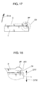
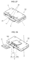
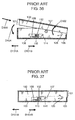
- Figs. 36 and 37 are each a side view showing a configuration of such a disk unit.
- Fig. 36 shows a disk-medium insertion hole opened in such a way that a disk medium (not shown) can be inserted or ejected.
- Fig. 37 shows the closed disk-medium insertion hole.
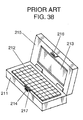
- Such a complex unit has the following problem, though it is easily operable.
- a user can move the slider operation portion 112 in the direction of the arrow D101A and eject a disk medium even while the unit is making a recording or a reproduction for the disk medium.
- the disk medium may be ejected while rotating and hit a member or the like around it accidentally thus damaging the disk medium itself. Further, its turning force can cause the disk medium to fly out.
- a disk-shaped information recording medium can be prevented from flying out accidentally while the apparatus is in operation.
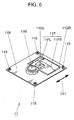
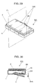
- Fig. 6 shows a schematic configuration of the disk drive portion 11.
- the disk drive portion 11 includes a disk motor 11M, a pickup 11P, a drive-portion base 11B, guide shafts 11GL and 11GR, and vibration-isolation dampers 11S.
- the disk motor 11M rotates the disk medium 31 placed and fixed there.
- the pickup 11P is formed by a pickup base portion 11PB and a lens portion 11PL mounted on there. It is guided and held by the two guide shafts 11GL and 11GR in such a way that it can move in the directions of an arrow D11 parallel to a specific radius direction of the disk medium 31 placed on the disk motor 11M. From the lens portion 11PL, a laser beam of a semiconductor laser or the like irradiates the disk medium 31 as the optical disk.
- the pickup 11P conduct recording and/or reproduction on an information recording surface of the disk medium 31.
- the drive-portion base 11B holds the disk motor 11M and the guide shafts 11GL and 11GR.
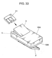
- reference numeral and character 2P denotes a stopper pressing portion which is united to the lid body 2 near the swing supporting portion 1AA and that can press the ejection-stopper press portion 7A in the direction of an arrow D7W when the lid body 2 swings in the direction of the arrow D1A.
- the stopper pressing portion 2P includes a first press surface 2K1 and a second press surface 2K2.
- the first press surface 2K1 is an inclined surface united to an edge part of the lid body 2 in such a way that the distance from the swing center of the lid body 2 to the radius directions becomes gradually longer as the lid body 2 opens.
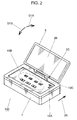
- the display 2B as the display surface of the lid body 2 should preferably be closed face down in such a way that the lid body 2 lies at a narrower angle than 45 degrees to the apparatus body 1. More desirably, it should be less than 30 degrees, and far more desirably, below 15 degrees.
- the main-power switch 1SA and the operation-switch group 1SB as well as view the display 2B in the disk apparatus 100.
- the user has already turned off the power of the disk apparatus 100 and is not now making a recording and a reproduction for the disk medium 31 in the disk drive portion 11. In other words, it is highly expected that the user is trying to exchange the disk medium 31 by sliding the lock slider 4 and opening the drive-portion cover 3.
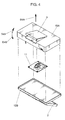
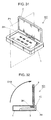
- the configuration for swinging the drive-portion cover 3 in the direction of the arrow D4A is used as the configuration for opening it.
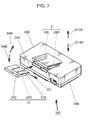
- a disk medium may move and open in parallel to the direction of an arrow D14A shown in Fig. 7 and move and close in parallel to the direction of an arrow D14B after a disk medium is inserted.
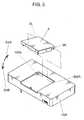
- the blocking hook 2H prevents the drive-portion cover 3 from opening when the lid body 2 is kept open.
- the fixation hook 3H corresponds to the hooked portion disposed in the drive-portion cover 3 and is hooked by the blocking hook 2H as the hooking portion.
- the blocking hook 2H protrudes from a middle part of the swing hinge portion 2A of the lid body 2. It comes into a passage hole 1C formed in the apparatus body 1 when the lid body 2 opens in the direction of the arrow D1A.
- the fixation hook 3H is united with a bridge part between the two cartridge guides 3SL and 3SR of the drive-portion cover 3.
- the drive-portion cover 3 is hindered from opening while the lid body 2 is open, in other words, while the disk apparatus 101 is in operation. Therefore, similarly to the first embodiment, the disk medium 31 is not supposed to be accidentally taken out while a reproduction or a recording is being made for the disk 31D. Consequently, the rotating disk 31D can be prevented from flying out at the user, or a laser beam from a semiconductor laser can be kept from entering the eyes of the user. This helps keep the user safer.
- the lock mechanism when the display unit is opened with respect to the body unit, the lock mechanism keeps the disk insertion-and-ejection mechanism in a state where the disk-shaped information recording medium cannot be inserted and ejected. Hence, the information recording medium is not supposed to be taken out while the disk drive is making a recording or a reproduction for the information recording medium. This makes it possible to prevent the information recording medium from fly ing out or being exposed while rotating. Besides, an operation of the lock mechanism interlocks with a relative movement of the display unit with respect to the body unit. Thus, using a simple configuration, the locking state can be automatically maintained as the display unit opens.
- the locking state of the lock mechanism be released only when the display unit is in the closed state with respect to the body unit.
- the lock retention member hooks and stops a part of the slider. Therefore, using a simple configuration, the disk insertion-and-ejection mechanism can be kept locked firmly on the body unit.
- the disk insertion-and-ejection mechanism can be prohibited from opening.
- the disk insertion-and-ejection mechanism can be permitted to open. Therefore, using a simple configuration and without deteriorating the operability by the user, the information recording medium can be certainly prevented from flying out or being exposed while rotating because the user operates it by mistake.
Landscapes
- Feeding And Guiding Record Carriers (AREA)
Applications Claiming Priority (1)
| Application Number | Priority Date | Filing Date | Title |
|---|---|---|---|
| JP2007123187 | 2007-05-08 |
Publications (3)
| Publication Number | Publication Date |
|---|---|
| EP1990802A2 true EP1990802A2 (de) | 2008-11-12 |
| EP1990802A3 EP1990802A3 (de) | 2010-10-20 |
| EP1990802B1 EP1990802B1 (de) | 2012-07-04 |
Family
ID=39495741
Family Applications (1)
| Application Number | Title | Priority Date | Filing Date |
|---|---|---|---|
| EP08155878A Not-in-force EP1990802B1 (de) | 2007-05-08 | 2008-05-08 | Plattenapparatus und Laufwerk |
Country Status (3)
| Country | Link |
|---|---|
| US (1) | US8181192B2 (de) |
| EP (1) | EP1990802B1 (de) |
| JP (1) | JP4954937B2 (de) |
Families Citing this family (4)
| Publication number | Priority date | Publication date | Assignee | Title |
|---|---|---|---|---|
| US9836084B2 (en) * | 2014-03-28 | 2017-12-05 | Intel Corporation | Inferred undocking for hybrid tablet computer |
| NL2023857B1 (en) * | 2019-09-19 | 2021-05-25 | Microsoft Technology Licensing Llc | Systems and methods for dynamically adjusting opening force |
| WO2023122159A2 (en) * | 2021-12-22 | 2023-06-29 | Invue Security Products Inc. | Data center security systems and devices |
| US11849561B2 (en) | 2021-12-22 | 2023-12-19 | In Vue Security Products Inc. | Data center security systems and devices |
Citations (3)
| Publication number | Priority date | Publication date | Assignee | Title |
|---|---|---|---|---|
| JPH08235718A (ja) | 1995-02-27 | 1996-09-13 | Nippon Columbia Co Ltd | 記録媒体記録再生機及びイジェクト機構 |
| JPH1049254A (ja) | 1996-08-06 | 1998-02-20 | Nec Data Terminal Ltd | 携帯端末装置 |
| JP2007123187A (ja) | 2005-10-31 | 2007-05-17 | Canon Inc | 電子機器及びその制御方法 |
Family Cites Families (11)
| Publication number | Priority date | Publication date | Assignee | Title |
|---|---|---|---|---|
| JPS57162148A (en) * | 1981-03-30 | 1982-10-05 | Sony Corp | Rotating recording medium reproducer |
| US5323291A (en) * | 1992-10-15 | 1994-06-21 | Apple Computer, Inc. | Portable computer and docking station having an electromechanical docking/undocking mechanism and a plurality of cooperatively interacting failsafe mechanisms |
| KR100422500B1 (ko) * | 1997-03-25 | 2004-06-26 | 삼성전자주식회사 | 전원 제어 모드 변환부를 가지는 휴대용 컴퓨터 |
| JPH11232836A (ja) * | 1998-02-12 | 1999-08-27 | Toshiba Corp | 多層情報層を有する情報記憶媒体及び多目的情報処理装置 |
| JP2002288974A (ja) * | 2001-03-22 | 2002-10-04 | Sony Corp | 電子機器 |
| KR100762391B1 (ko) * | 2001-07-10 | 2007-10-02 | 엘지전자 주식회사 | 휴대형 디스크 재생장치 |
| JP4119762B2 (ja) * | 2003-01-31 | 2008-07-16 | 富士フイルム株式会社 | 記録メデイア保護機構 |
| CN2706834Y (zh) * | 2004-05-28 | 2005-06-29 | 鸿富锦精密工业(深圳)有限公司 | 光盘播放器顶盖启闭装置 |
| CN2745176Y (zh) * | 2004-09-08 | 2005-12-07 | 鸿富锦精密工业(深圳)有限公司 | 光盘播放器 |
| US7574715B2 (en) * | 2005-07-20 | 2009-08-11 | Apple Inc. | Disk drive media access system |
| TWI301338B (en) | 2006-08-30 | 2008-09-21 | Asustek Comp Inc | Electrionic apparatus with rotatable cover |
-
2008
- 2008-04-24 JP JP2008113728A patent/JP4954937B2/ja not_active Expired - Fee Related
- 2008-05-08 US US12/117,566 patent/US8181192B2/en not_active Expired - Fee Related
- 2008-05-08 EP EP08155878A patent/EP1990802B1/de not_active Not-in-force
Patent Citations (3)
| Publication number | Priority date | Publication date | Assignee | Title |
|---|---|---|---|---|
| JPH08235718A (ja) | 1995-02-27 | 1996-09-13 | Nippon Columbia Co Ltd | 記録媒体記録再生機及びイジェクト機構 |
| JPH1049254A (ja) | 1996-08-06 | 1998-02-20 | Nec Data Terminal Ltd | 携帯端末装置 |
| JP2007123187A (ja) | 2005-10-31 | 2007-05-17 | Canon Inc | 電子機器及びその制御方法 |
Also Published As
| Publication number | Publication date |
|---|---|
| US20080282276A1 (en) | 2008-11-13 |
| JP2008305534A (ja) | 2008-12-18 |
| EP1990802A3 (de) | 2010-10-20 |
| JP4954937B2 (ja) | 2012-06-20 |
| US8181192B2 (en) | 2012-05-15 |
| EP1990802B1 (de) | 2012-07-04 |
Similar Documents
| Publication | Publication Date | Title |
|---|---|---|
| EP1990802B1 (de) | Plattenapparatus und Laufwerk | |
| EP1443513B1 (de) | Kassette als behälter für ein aufzeichnungsmedium | |
| KR101059493B1 (ko) | 디스크 카트리지용 셔터 부재, 디스크 카트리지 및 디스크 기록 또는 재생 장치 | |
| WO2000021083A1 (en) | Recording and/or reproducing device using disk cartridge | |
| JP4706169B2 (ja) | ディスクカートリッジ | |
| KR101059093B1 (ko) | 디스크 카트리지 | |
| JP4081885B2 (ja) | 磁気ヘッド装置 | |
| JP4221786B2 (ja) | ホルダ装置を用いたディスク記録及び/又は再生装置 | |
| JP4250789B2 (ja) | 磁気ヘッドの昇降制御装置 | |
| JP4706185B2 (ja) | ディスクカートリッジ | |
| KR101058858B1 (ko) | 디스크 카트리지 | |
| JP4423945B2 (ja) | ディスクカートリッジ | |
| JP2001143359A (ja) | ディスク駆動装置 | |
| JP3002465B2 (ja) | ディスクカ―トリッジ | |
| JP4692838B2 (ja) | ディスクドライブ装置及び電子機器 | |
| US7853965B2 (en) | Disk drive | |
| JP2005063638A (ja) | ディスクカートリッジ及びディスク記録及び/又は再生装置 | |
| JP3046279B2 (ja) | ディスクカートリッジ | |
| JP4547982B2 (ja) | ディスクカートリッジ | |
| JP2005050426A (ja) | ディスクカートリッジ | |
| JPH0765564A (ja) | 携帯式プレーヤ | |
| JP2005158201A (ja) | ディスク駆動装置 | |
| JP2005063636A (ja) | ディスクカートリッジ及びディスク記録及び/又は再生装置 | |
| JP2008016134A (ja) | ディスクドライブ装置及び電子機器 | |
| JP2000195216A (ja) | ディスクカ―トリッジ |
Legal Events
| Date | Code | Title | Description |
|---|---|---|---|
| PUAI | Public reference made under article 153(3) epc to a published international application that has entered the european phase |
Free format text: ORIGINAL CODE: 0009012 |
|
| AK | Designated contracting states |
Kind code of ref document: A2 Designated state(s): AT BE BG CH CY CZ DE DK EE ES FI FR GB GR HR HU IE IS IT LI LT LU LV MC MT NL NO PL PT RO SE SI SK TR |
|
| AX | Request for extension of the european patent |
Extension state: AL BA MK RS |
|
| RAP1 | Party data changed (applicant data changed or rights of an application transferred) |
Owner name: PANASONIC CORPORATION |
|
| PUAL | Search report despatched |
Free format text: ORIGINAL CODE: 0009013 |
|
| AK | Designated contracting states |
Kind code of ref document: A3 Designated state(s): AT BE BG CH CY CZ DE DK EE ES FI FR GB GR HR HU IE IS IT LI LT LU LV MC MT NL NO PL PT RO SE SI SK TR |
|
| AX | Request for extension of the european patent |
Extension state: AL BA MK RS |
|
| 17P | Request for examination filed |
Effective date: 20110224 |
|
| AKX | Designation fees paid |
Designated state(s): DE FR GB |
|
| GRAP | Despatch of communication of intention to grant a patent |
Free format text: ORIGINAL CODE: EPIDOSNIGR1 |
|
| RIN1 | Information on inventor provided before grant (corrected) |
Inventor name: TOMITA, HIRONORI Inventor name: TAKIZAWA, TERUYUKI Inventor name: INATA, MASAHIRO Inventor name: EZAWA, KOZO |
|
| GRAS | Grant fee paid |
Free format text: ORIGINAL CODE: EPIDOSNIGR3 |
|
| GRAA | (expected) grant |
Free format text: ORIGINAL CODE: 0009210 |
|
| AK | Designated contracting states |
Kind code of ref document: B1 Designated state(s): DE FR GB |
|
| REG | Reference to a national code |
Ref country code: GB Ref legal event code: FG4D |
|
| REG | Reference to a national code |
Ref country code: DE Ref legal event code: R096 Ref document number: 602008016949 Country of ref document: DE Effective date: 20120830 |
|
| PLBE | No opposition filed within time limit |
Free format text: ORIGINAL CODE: 0009261 |
|
| STAA | Information on the status of an ep patent application or granted ep patent |
Free format text: STATUS: NO OPPOSITION FILED WITHIN TIME LIMIT |
|
| 26N | No opposition filed |
Effective date: 20130405 |
|
| REG | Reference to a national code |
Ref country code: DE Ref legal event code: R097 Ref document number: 602008016949 Country of ref document: DE Effective date: 20130405 |
|
| GBPC | Gb: european patent ceased through non-payment of renewal fee |
Effective date: 20130508 |
|
| PG25 | Lapsed in a contracting state [announced via postgrant information from national office to epo] |
Ref country code: DE Free format text: LAPSE BECAUSE OF NON-PAYMENT OF DUE FEES Effective date: 20131203 |
|
| REG | Reference to a national code |
Ref country code: DE Ref legal event code: R119 Ref document number: 602008016949 Country of ref document: DE Effective date: 20131203 |
|
| REG | Reference to a national code |
Ref country code: FR Ref legal event code: ST Effective date: 20140131 |
|
| PG25 | Lapsed in a contracting state [announced via postgrant information from national office to epo] |
Ref country code: GB Free format text: LAPSE BECAUSE OF NON-PAYMENT OF DUE FEES Effective date: 20130508 |
|
| PG25 | Lapsed in a contracting state [announced via postgrant information from national office to epo] |
Ref country code: FR Free format text: LAPSE BECAUSE OF NON-PAYMENT OF DUE FEES Effective date: 20130531 |