EP1990683A2 - Toner et appareil de formation d'images, procédé de formation d'images et cartouche de traitement utilisant le toner - Google Patents
Toner et appareil de formation d'images, procédé de formation d'images et cartouche de traitement utilisant le toner Download PDFInfo
- Publication number
- EP1990683A2 EP1990683A2 EP08155945A EP08155945A EP1990683A2 EP 1990683 A2 EP1990683 A2 EP 1990683A2 EP 08155945 A EP08155945 A EP 08155945A EP 08155945 A EP08155945 A EP 08155945A EP 1990683 A2 EP1990683 A2 EP 1990683A2
- Authority
- EP
- European Patent Office
- Prior art keywords
- toner
- image
- resin
- roller
- acid
- Prior art date
- Legal status (The legal status is an assumption and is not a legal conclusion. Google has not performed a legal analysis and makes no representation as to the accuracy of the status listed.)
- Granted
Links
Images


Classifications
-
- G—PHYSICS
- G03—PHOTOGRAPHY; CINEMATOGRAPHY; ANALOGOUS TECHNIQUES USING WAVES OTHER THAN OPTICAL WAVES; ELECTROGRAPHY; HOLOGRAPHY
- G03G—ELECTROGRAPHY; ELECTROPHOTOGRAPHY; MAGNETOGRAPHY
- G03G9/00—Developers
- G03G9/08—Developers with toner particles
- G03G9/087—Binders for toner particles
- G03G9/08742—Binders for toner particles comprising macromolecular compounds obtained otherwise than by reactions only involving carbon-to-carbon unsaturated bonds
- G03G9/08755—Polyesters
-
- G—PHYSICS
- G03—PHOTOGRAPHY; CINEMATOGRAPHY; ANALOGOUS TECHNIQUES USING WAVES OTHER THAN OPTICAL WAVES; ELECTROGRAPHY; HOLOGRAPHY
- G03G—ELECTROGRAPHY; ELECTROPHOTOGRAPHY; MAGNETOGRAPHY
- G03G9/00—Developers
- G03G9/08—Developers with toner particles
- G03G9/087—Binders for toner particles
- G03G9/08702—Binders for toner particles comprising macromolecular compounds obtained by reactions only involving carbon-to-carbon unsaturated bonds
- G03G9/08706—Polymers of alkenyl-aromatic compounds
- G03G9/08708—Copolymers of styrene
- G03G9/08711—Copolymers of styrene with esters of acrylic or methacrylic acid
-
- G—PHYSICS
- G03—PHOTOGRAPHY; CINEMATOGRAPHY; ANALOGOUS TECHNIQUES USING WAVES OTHER THAN OPTICAL WAVES; ELECTROGRAPHY; HOLOGRAPHY
- G03G—ELECTROGRAPHY; ELECTROPHOTOGRAPHY; MAGNETOGRAPHY
- G03G9/00—Developers
- G03G9/08—Developers with toner particles
- G03G9/087—Binders for toner particles
- G03G9/08775—Natural macromolecular compounds or derivatives thereof
-
- G—PHYSICS
- G03—PHOTOGRAPHY; CINEMATOGRAPHY; ANALOGOUS TECHNIQUES USING WAVES OTHER THAN OPTICAL WAVES; ELECTROGRAPHY; HOLOGRAPHY
- G03G—ELECTROGRAPHY; ELECTROPHOTOGRAPHY; MAGNETOGRAPHY
- G03G9/00—Developers
- G03G9/08—Developers with toner particles
- G03G9/087—Binders for toner particles
- G03G9/08784—Macromolecular material not specially provided for in a single one of groups G03G9/08702 - G03G9/08775
- G03G9/08786—Graft polymers
-
- G—PHYSICS
- G03—PHOTOGRAPHY; CINEMATOGRAPHY; ANALOGOUS TECHNIQUES USING WAVES OTHER THAN OPTICAL WAVES; ELECTROGRAPHY; HOLOGRAPHY
- G03G—ELECTROGRAPHY; ELECTROPHOTOGRAPHY; MAGNETOGRAPHY
- G03G9/00—Developers
- G03G9/08—Developers with toner particles
- G03G9/087—Binders for toner particles
- G03G9/08784—Macromolecular material not specially provided for in a single one of groups G03G9/08702 - G03G9/08775
- G03G9/08795—Macromolecular material not specially provided for in a single one of groups G03G9/08702 - G03G9/08775 characterised by their chemical properties, e.g. acidity, molecular weight, sensitivity to reactants
-
- G—PHYSICS
- G03—PHOTOGRAPHY; CINEMATOGRAPHY; ANALOGOUS TECHNIQUES USING WAVES OTHER THAN OPTICAL WAVES; ELECTROGRAPHY; HOLOGRAPHY
- G03G—ELECTROGRAPHY; ELECTROPHOTOGRAPHY; MAGNETOGRAPHY
- G03G9/00—Developers
- G03G9/08—Developers with toner particles
- G03G9/087—Binders for toner particles
- G03G9/08784—Macromolecular material not specially provided for in a single one of groups G03G9/08702 - G03G9/08775
- G03G9/08797—Macromolecular material not specially provided for in a single one of groups G03G9/08702 - G03G9/08775 characterised by their physical properties, e.g. viscosity, solubility, melting temperature, softening temperature, glass transition temperature
Definitions
- the present invention relates to a toner to be used in image formation based on electrophotography such as copiers, printers, facsimiles, and electrostatic recording devices.
- the present invention also relates to an image forming apparatus, an image forming method and a process cartridge each of which uses the toner.
- an unfixed toner image is formed on a recording medium such as recording sheet, printing paper, photosensitive paper and electrostatic recording paper by using a direct transfer method or an indirect transfer method through an image formation process such as electrophotographic recording, electrostatic recording and magnetic recording.
- a fixing unit used for fixing such an unfixed toner image for example, contact heating methods, such as heating roller method, film heating method and electromagnetic induction heating method, are widely employed.
- an electrophotographic toner (hereinafter, may be simply referred to as "toner")
- a toner which is excellent in low-temperature fixing property is requested.
- a toner having properties of anti-offset property and storage stability (blocking resistance) which are contradictory to the low-temperature fixing property.
- the low-molecular weight polyester resin prepared using an aliphatic alcohol when used, the storage stability of the toner is degraded because the polyester resin has a low glass transition temperature due to its structure and it is difficult to satisfy low-temperature fixing property, anti-offset property and storage stability at a high level.
- the low-molecular weight polyester resin prepared using an aliphatic alcohol since the low-molecular weight polyester resin prepared using an aliphatic alcohol has low mechanical strength, it may cause a problem with occurrence of toner fine particles and contamination inside the used developing device and developing sleeves when the toner is agitated and sheared in the developing device.
- the used toner is requested to have releasing property (may be referred to as "anti-offset property") to heating members is required.
- the anti-offset property can be improved by containing a releasing agent in a toner, and how the releasing agent is present inside the toner greatly affect the releasing property. It is desired that the releasing agent be uniformly dispersed in the toner in terms of stability of the quality, however, when the releasing agent is excessively finely dispersed in the toner, the releasing agent hardly exudes out of the toner surface at the time of heating. Thus, it is preferable that the releasing agent be dispersed so as to have a moderate dispersion diameter. However, for a polyester resin prepared using an aliphatic alcohol, there is a problem that it is highly soluble in generally used releasing agents and is poor in releasing property.
- a resin grafted with a vinyl resin is used as a dispersing agent in a releasing agent such as polyolefin, and the releasing agent is moderately dispersed in a toner (for example, see Japanese Patent Application Laid-Open (JP-A) Nos. 2000-305319 , 2003-98726 , Japanese Patent (JP-B) Nos. 3597525 and 3801487 ).
- JP-A Japanese Patent Application Laid-Open
- JP-B Japanese Patent Nos. 3597525 and 3801487
- dispersing agents prepared in accordance with these proposals are not suitable for polyester resins prepared using aliphatic alcohol, and these proposals are incapable of improving the releasing property of toner.
- a toner that is excellent in all of the low-temperature fixing property, anti-offset property, storage stability, mechanical strength, anti-fouling property to developing devices, toner filming resistance to latent electrostatic image bearing members and carrier particles, and pulverizability and is capable of forming high-quality images over a long period of time
- an image forming apparatus and related technologies which are capable of forming extremely high-quality images using a toner with no change in color tone being recognized and with no abnormal images such as a reduction in image density and background smear being observed for a long period of time, those having satisfactory performance have not yet been provided so far.
- Currently, further improvements and developments are desired.
- the present invention aims to provide a toner that is excellent in all of the low-temperature fixing property, anti-offset property, storage stability, mechanical strength, anti-fouling property to developing devices, toner filming resistance to latent electrostatic image bearing members and carrier particles, and pulverizability and is capable of forming high-quality images over a long period of time.
- the present invention also aims to provide an image forming apparatus, an image forming method and a process cartridge each of which uses the toner of the present invention and is capable of forming extremely high-quality images with no change in color tone being recognized and with no abnormal images such as a reduction in image density and background smear being observed for a long period of time.
- the toner of the present invention contains at least a binder resin, a releasing agent and a colorant, wherein the binder resin contains at least a polyester resin (A) having a softening point Tm (A) of 120°C to 160°C, a polyester resin (B) having a softening point Tm (B) of 80°C or more and less than 120°C and a composite resin (C) containing a condensation polymerization monomer and an addition polymerization monomer, at least any one of the polyester resins (A) and (B) is a polyester resin prepared by condensation-polymerizing an alcohol component substantially composed of only aliphatic alcohol with a carboxylic acid component, and 65 mole% or more of the alcohol component is 1,2-propanediol.
- the binder resin contains at least a polyester resin (A) having a softening point Tm (A) of 120°C to 160°C, a polyester resin (B) having a softening point Tm (B) of 80°C
- the polyester resin (A) having high-softening point contributes to an improvement in anti-offset property
- the polyester resin (B) having low-softening point contributes to an improvement in low-temperature fixing property.
- the use in combination of these polyester resins is effective in satisfying both the low-temperature fixing property and anti-offset property.
- the 1,2-propanediol which is a branched chain alcohol having 3 carbon atoms is effective in improving low-temperature fixing property with maintaining anti-offset property as compared to an alcohol having 2 or less carbon atoms, and the use thereof allows for fixing an image at an extremely low temperature and improving storage stability.
- the composite resin (C) composed of a condensation polymerization monomer and an addition polymerization monomer is excellently dispersed in a blend of the polyester resins (A) and (B) of the present invention and is capable of uniformly dispersing generally used releasing agents in the resin components with an optimum dispersion diameter without making them excessively soluble in the resin components, and thus the releasing property of the toner to fixing members is excellently improved. Furthermore, the composite resin (C) is more excellent in mechanical strength than a polyester substantially composed of an aliphatic alcohol and imparts resistance to stirring hazards to the toner in a developing device.
- the toner of the present invention becomes excellent in low-temperature fixing property, anti-offset property, storage stability, mechanical strength, anti-fouling property to developing devices, toner filming resistance to latent electrostatic image bearing members and carrier particles, and pulverizability and becomes capable of forming high-quality images.
- the developer of the present invention contains the toner of the present invention.
- a high-quality image can be obtained with keeping excellence in all of the low-temperature fixing property, anti-offset property, storage stability, mechanical strength, anti-fouling property to developing devices, toner filming resistance to latent electrostatic image bearing members and carrier particles.
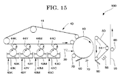
- the image forming apparatus of the present invention has at least a latent electrostatic image bearing member, a charging unit configured to charge the surface of the latent electrostatic image bearing member, an exposing unit configured to expose the charged surface of the latent electrostatic image bearing member to form a latent electrostatic image, a developing unit configured to develop the latent electrostatic image using a toner to form a visible image, a transfer unit configured to transfer the visible image onto a recording medium, and a fixing unit configured to fix the transferred image on the recording medium, and as the toner, the toner of the present invention is used.
- the charging unit is configured to uniformly charge the surface of the latent electrostatic image bearing member.
- the exposing unit is configured to expose the surface of the latent electrostatic image bearing member to form a latent electrostatic image.
- the developing unit is configured to develop the latent electrostatic image formed on the surface of the latent electrostatic image bearing member using a toner to form a visible image.
- the transfer unit is configured to transfer the visible image onto a recording medium.
- the fixing unit is configured to fix the transferred image on the recording medium.
- the toner of the present invention is used, and thus it is possible to form extremely high-quality images with no change in color tone and with no abnormal images such as a reduction in image density and background smear being observed for a long period of time.
- the image forming method of the present invention includes at least charging the surface of a latent electrostatic image bearing member, exposing the charged surface of the latent electrostatic image bearing member to form a latent electrostatic image, developing the latent electrostatic image using a toner to form a visible image, transferring the visible image onto a recording medium, and fixing the transferred image on the recording medium, and as the toner, the toner of the present invention is used.
- the surface of the latent electrostatic image bearing member is uniformly charged; in the exposing step, the surface of the latent electrostatic image bearing member is exposed to form a latent electrostatic image; in the developing step, the latent electrostatic image formed on the surface of the latent electrostatic image bearing member is developed using a toner to form a visible image; in the transferring step, the visible image is transferred onto a recording medium; and in the fixing step, the transferred image is fixed on the recording medium.
- the toner of the present invention is used, and thus it is possible to form extremely high-quality images with no change in color tone and with no abnormal images such as a reduction in image density and background smear being observed for a long period of time.
- the process cartridge of the present invention has at least a latent electrostatic image bearing member and a developing unit configured to develop a latent electrostatic image formed on the surface of the latent electrostatic image bearing member using a toner to form a visible image and is detachably mounted on an image forming apparatus main body. Since the process cartridge is excellent in user-friendliness and the toner of the present invention is used therein, it allows for forming extremely high-quality images with no change in color tone and with no abnormal images such as a reduction in image density and background smear being observed for a long period of time.
- the toner of the present invention contains at least a binder resin, a releasing agent and a colorant, contains external additives, and further contains other components in accordance with the necessity.
- the binder resin contains at least a polyester resin (A) having a softening point Tm (A) of 120°C to 160°C, a polyester resin (B) having a softening point Tm (B) of 80°C or more and less than 120°C and a composite resin (C) containing a condensation polymerization monomer and an addition polymerization monomer.
- the polyester resins (A) and (B) can be obtained by condensation-polymerizing an alcohol component and a carboxylic acid component.
- the softening point Tm (A) of the polyester resin (A) is 120°C to 160°C, preferably 130°C to 155°C, and more preferably 135°C to 155°C.
- the softening point Tm (B) of the polyester resin (B) is 80°C or more and less than 120°C, preferably 85°C to 115°C, and more preferably 90°C to 110°C.
- the difference of the Tm (A) minus the Tm (B), that is [ ⁇ Tm; Tm (A) - Tm (B)], is preferably 10°C or more, more preferably 15°C to 55°C, and still more preferably 20°C to 50°C.
- the mass ratio [(A) / (B)] of the polyester resin (A) to the polyester resin (B) is preferably 10/90 to 90/10, more preferably 20/80 to 80/20, and still more preferably 30/70 to 70/30.
- the polyester resin (A) having a high-softening point contributes to an improvement in anti-offset property
- the polyester resin (B) having a low-softening point contributes to an improvement in low-temperature fixing property.
- the use in combination of these polyester resins (A) and (B) is effective in satisfying both the low-temperature fixing property and anti-offset property.
- At least any one of the polyester resins (A) and (B) contains 65 mole% or more of 1,2-propanediol in the alcohol component and can be obtained by condensation-polymerizing an alcohol component substantially composed of only aliphatic alcohol with a carboxylic acid component.
- the 1,2-propanediol which is a branched chain alcohol having 3 carbon atoms, used in the alcohol component is effective in improving low-temperature fixing property with maintaining anti-offset property as compared to an alcohol having 2 or less carbon atoms and is effective in preventing a reduction in storage stability accompanied by a decrease in glass transition temperature as compared to a branched chain alcohol having 4 or more carbon atoms.
- the 1,2-propanediol exerts a remarkable effect that the use thereof allows for fixing an image at an extremely low temperature and improving storage stability.
- a polyester resin containing 1,2-propanediol as an alcohol component is excellent in solubility in releasing agents and easily dispersed therein. Particularly when the content of 1,2-propanediol is 65 mole% or more in the alcohol component, it exerts excellent low-temperature fixing property and anti-offset property.
- the alcohol component may contain alcohols other than 1,2-propanediol within the range where the purposes and effects of the present invention are not impaired, however, the content of 1,2-propanediol in the alcohol component is 65 mole% or more, preferably 70 mole% or more, more preferably 80 mole% or more, and still more preferably 90 mole% or more.
- divalent alcohol components other than 1,2-propandiol examples include 1,3-propanediol, ethylene glycols having a different carbon atoms, hydrogenated bisphenol A or aliphatic dialcohols such as alkylene (having 2 to 4 carbon atoms) oxide adducts (with average added moles: 1 to 16) thereof.
- the content of the divalent alcohol component in the alcohol component is preferably 60 mole% to 95 mole% and more preferably 65 mole% to 90 mole%.
- the alcohol component of the polyester resin (A) preferably contains 1,3-propanediol from the perspective of anti-offset property.
- the molar ratio (1,2-propanediol / 1.3-propanediol) of 1,2-propanediol to 1,3-propanediol in the alcohol component is preferably 99/1 to 65/35, more preferably 95/5 to 70/30, still more preferably 90/10 to 75/25, and particularly preferably 85/15 to 77/23.
- the alcohol component of at least any one of the polyester resins (A) and (B) may contain aromatic alcohols including alkylene oxide adducts of bisphenol A such as polyoxypropylene (2,2)-2,2-bis (4-hydroxyphenyl) propane, and polyoxyethylene (2,2)-2,2-bis (4-hydroxyphenyl) propane, however, the alcohol component of at least any one of the polyester resins (A) and (B) is substantially composed of only aliphatic alcohol, and it is preferred that both of the alcohol components of the polyester resins (A) and (B) are substantially composed of only aliphatic alcohol.
- the alcohol component substantially composed of aliphatic alcohol means that the content of the aliphatic alcohol in the alcohol component is 90 mole% or more, more preferably 95 mole% or more, still more preferably 98 mole% or more, and particularly preferably 99 mole% or more.
- the carboxylic acid component is not particularly limited and may be suitably selected in accordance with the intended use, however, it is preferable that an aliphatic dicarboxylic acid compound having 2 to 4 carbon atoms be contained in the carboxylic acid component.
- the aliphatic dicarboxylic acid compound having 2 to 4 carbon atoms include adipic acid, maleic acid, malic acid, succinic acid, fumaric acid, citraconic acid, itaconic acid or anhydrides of acids thereof. Of these, at least one aliphatic dicarboxylic acid compound selected from succinic acid, fumaric acid, citraconic acid and itaconic acid is preferable in terms of effectiveness in improving low-temperature fixing property, and itaconic acid is particularly preferable.
- the content of the aliphatic dicarboxylic acid having 2 to 4 carbon atoms in the carboxylic acid component is preferably 0.5 mole% to 20 mole% and more preferably 1 mole% to 10 mole% from the perspective of improving low-temperature fixing property and preventing decreases in glass transition temperature.
- a polyester resin that can be obtained by condensation-polymerizing such an aliphatic carboxylic acid compound having no aromatic rings with 1,2-propanediol allows for improving solubility in releasing agents, and thus the use thereof in combination with a releasing agent makes it possible to further improve toner filming resistance.
- a rosin be contained in the carboxylic component.
- a rosin which has a polycyclic aromatic ring the water absorbing property held by a conventional aliphatic alcohol polyester is reduced to thereby further improve the effect of preventing a reduction in charged amount under high-temperature and high-humidity conditions.
- the rosin is a natural resin obtained from pine tree (pinus rigidia) and the main component thereof is a resin acid such as abietic acid, neoabietic acid, palustrene acid, pimaric acid, isopimaric acid, sandrakopimaric acid, and dehydroabietic acid or a mixture thereof.
- the rosin is broadly classified into tall rosin obtained from tall oil that can be obtained as a by-product in the course of producing a pulp, gum rosin obtained from crude pine rosin, wood rosin obtained from pine stubs and the like.
- the rosin used in the present invention is preferably tall rosin from the perspective of low-temperature fixing property.
- the rosin may be a modified rosin such as disproportionated rosin and hydrogenated rosin, however, in the present invention, it is preferable to use a so-called "crude rosin” ,which is not modified, from the perspective of low-temperature fixing property and storage stability.
- the rosin is preferably a purified rosin from the perspective of improving storage stability and deodorization.
- the purified rosin is a rosin from which impurities have been removed by purification process.
- major impurities include 2-methylpropane, acetaldehyde, 3-methyl-2-butanone, 2-methylpropanoic acid, butanoic acid, pentanoic acid, n-hexanal, octane, hexanoic acid, benzaldehyde, 2-pentylfuran, 2,6-dimethyl cyclohexanone, 1-methyl-2-(1-methylethyl) benzene, 3,5-dimethyl 2-cyclohexane, and 4-(1-methylethyl) benzaldehyde.
- peak intensities of three types of impurities from among the above-mentioned impurities, i.e., hexanoic acid, pentanoic acid and benzaldehyde, detected as volatilized components by Headspace GC-MS can be used as indicators of the purified rosin.
- the reason of using volatilized components as indicators, instead of using the absolute amount of impurities is that the use of a purified rosin in the present invention contributes deodorization, which is one of the improved points of the present invention, as compared to conventional polyester resins each of which contains rosin.
- the purified rosin mentioned in the present invention is a rosin of which in the hereinafter described measurement conditions based on Headspace GC-MS, the peak intensity of hexanoic acid is 0.8 ⁇ 10 7 or less, the peak intensity of pentanoic acid is 0.4 ⁇ 10 7 or less, and the peak intensity of benzaldehyde is 0.4 ⁇ 10 7 or less. Further, from the perspective of storage stability and deodorization, the peak intensity of hexanoic acid is preferably 0.6 ⁇ 10 7 or less and more preferably 0.5 ⁇ 10 7 or less.
- the peak intensity of pentanoic acid is preferably 0.3 ⁇ 10 7 or less and more preferably 0.2 ⁇ 10 7 or less.
- the peak intensity of benzaldehyde is preferably 0.3 ⁇ 10 7 or less and more preferably 0.2 ⁇ 10 7 or less.
- the amount of impurities of n-hexanal and 2-pentylfuran be reduced, in addition to the above-mentioned three impurities.
- the peak intensity of n-hexanal is preferably 1.7 ⁇ 10 7 or less, more preferably 1.6 ⁇ 10 7 or less, and still more preferably 1.5 ⁇ 10 7 or less.
- the peak intensity of 2-pentylfuran is preferably 1.0 ⁇ 10 7 or less, more preferably 0.9 ⁇ 10 7 or less, and still more preferably 0.8 ⁇ 10 7 or less.
- the purification method of the rosin is not particularly limited and known methods in the art are utilized. Examples thereof include distillation, recrystallization, and extraction.
- the rosin is preferably purified by distillation.
- the distillation method for example, the methods described in Japanese Patent Application Laid-Open (JP-A) No. 7-286139 can be used, such as reduced-pressure distillation, molecular distillation and steam distillation.
- the rosin is preferably purified by reduced-pressure distillation.
- a distillation is generally carried out under a pressure of 6.67 kPa or less and a still temperature of 200°C to 300°C, and distillation methods such as thin-layer distillation, rectification distillation, including commonly used simple distillation can be used.
- 2% by mass to 10% by mass of high-molecular weight substances is removed as a pitch portion, and 2% by mass to 10% by mass of an initial fraction is removed.
- the softening point of the purified rosin is preferably 50°C to 100°C, more preferably 60°C to 90°C, and still more preferably 65°C to 85°C.
- the softening point of the purified rosin in the present invention means a softening point measured when a rosin is melted once by the method to be described below and then the rosin is naturally cooled for one hour under an environment of a temperature of 25°C and a relative humidity of 50%.
- the acid value of the purified rosin is preferably 100 mgKOH/g to 200 mgKOH/g, more preferably 130 mgKOH/g to 180 mgKOH/g, and still more preferably 150 mgKOH/g to 170 mgKOH/g.
- the content of the purified rosin in the carboxylic acid component is preferably 2 mole% to 50 mole%, more preferably 5 mole% to 40 mole%, and still more preferably 10 mole% to 30 mole%.
- the carboxylic acid component may contain the aliphatic carboxylic acid compound and carboxylic acid compounds other than rosins within the range where the effects of the present invention are not impaired. From the perspective of securing the desired glass transition temperature, it is preferable that aromatic dicarboxylic acids such as phthalic acid, isophthalic acid and terephthalic acid be contained in the carboxylic acid component.
- aromatic dicarboxylic acids such as phthalic acid, isophthalic acid and terephthalic acid be contained in the carboxylic acid component.
- the content of the aromatic dicarboxylic acid in the carboxylic acid component is preferably 40 mole% to 95 mole%, more preferably 50 mole% to 90 mole%, and still more preferably 60 mole% to 80 mole%.
- the polyester resin is preferably a crosslinked polyester resin, and it is preferred that a trivalent or higher raw monomer be contained in at least any one of the alcohol component and the carboxylic acid component.
- the content of the trivalent or higher raw monomer in the total amount of the alcohol component and the carboxylic acid component is preferably 0 mole% to 40 mole% and more preferably 5 mole% to 30 mole%.
- a trivalent or higher polyhydric carboxylic acid compound in the trivalent or higher raw monomer for example, trimellitic acid or a derivative thereof is preferable.
- trimellitic acid or a derivative thereof for a trivalent or higher polyhydric alcohol, for example, glycerin, pentaerythritol, trimethylolpropane, sorbitol or alkylene (having 2 to 4 carbon atoms) oxide adducts (average added moles: 1 to 16) and the like are exemplified.
- glycerin is particularly preferable because it not only acts as a crosslinker, but also is effective in improvements in low-temperature fixing property.
- the alcohol component of at least any one of the polyester resins (A) and (B) contain glycerin.
- the content of the glycerin in the alcohol component is preferably 5 mole% to 40 mole%, and more preferably 10 mole% to 35 mole%.
- a condensation polymerization reaction between the alcohol component and the carboxylic acid component is preferably carried out in the presence of an esterified catalyst.
- the esterified catalyst include Lewis acids such as p-toluene sulfonic acid; titanium compounds, and tin (II) compounds having no Sn-C bond. Tthese esterified catalysts may be used alone or two of them may be used in combination. Of these, titanium compounds and tin (II) compounds having no Sn-C bond are particularly preferable.
- titanium compound a titanium compound having a Ti-O bond is preferable, and a compound containing an alkoxy group, an alkenyloxy group or an acyloxy group each having the total carbon atoms of 1 to 28 is more preferable.
- titanium compound examples include titanium diisopropylate bis(triethanolaminate) [Ti (C 6 H 14 O 3 N) 2 (C 3 H 7 O) 2 ], titanium diisopropylate bis(diethanolaminate) [Ti (C 4 H 10 O 2 N) 2 (C 3 H 7 O) 2 ], titanium dipentylate bis(triethanolaminate) [Ti (C 6 H 14 O 3 N) 2 (C 5 H 11 O) 2 ], titanium diethylate bis(triethanolaminate) [Ti (C 6 H 14 O 3 N) 2 (C 2 H 5 O) 2 ], titanium dihydroxy octylate bis(triethanolaminate) [Ti (C 6 H 14 O 3 N) 2 (OHC 8 H 16 O) 2 ], titanium distearate bis(triethanolaminate) [Ti (C 6 H 14 O 3 N) 2 (C 18 H 37 O) 2 ], titanium triisopropylate triethanolaminate [Ti (C 6 H 14 O 3 N) 1 (C 3 H 7
- titanium diisopropylate bis(triethanolaminate), titanium diisopropylate bis(diethanolaminate), and titanium dipentylate bis(triethanolaminate) are particularly preferable. These titanium compounds are commercially available from Matsumoto Trading Co., Ltd.
- Ti (C 4 H 9 O) 4 tetra-n-butyltitanate
- Ti (C 3 H 7 O) 4 tetrapropyl titanate
- Ti (C 18 H 37 O) 4 tetrastearyl titanate
- Ti (C 18 H 37 O) 4 tetrastearyl titanate
- Ti (C 18 H 37 O) 4 tetrastearyl titanate
- Ti (C 18 H 37 O) 4 tetramyristyl titanate
- Ti (C 14 H 29 O) 4 tetraoctyl titanate
- dimyristyl dioctyl titanate Ti (C 14 H 29 O) 2 (C 8 H 17 O) 2 ].
- titanium compounds can be obtained, for example, by reacting titanium halide with a corresponding alcohol and are commercially available from NISSO Co., Ltd.
- the existing amount of the titanium compound to 100 parts by mass of the total amount of the alcohol component and the carboxylic acid component is preferably 0.01 parts by mass to 1.0 part by mass and more preferably 0.1 parts by mass to 0.7 parts by mass.
- tin (II) compound having no Sn-C bond a tin (II) compound having an Sn-O bond, a tin (II) compound having an Sn-X (X indicates a halogen atom) bond and the like are preferable, and a tin (II) compound having an Sn-O bond is more preferable.
- tin (II) compound having an Sn-O bond examples include tin (II) carboxylate containing a carboxylic group having 2 to 28 carbon atoms such as tin (II) oxalate, tin (II) diacetate, tin (II) dioctanoate, tin(II) dilaurate, tin(II) distearate, and tin(II) dioleate; dialkoxy tin (II) containing an alkoxy group having 2 to 28 carbon atoms such as dioctyloxy tin (II), dilauroxy tin (II), distearoxy tin (II), and dioleyloxy tin (II); and tin (II) oxides; and tin (II) sulfates.
- tin (II) carboxylate containing a carboxylic group having 2 to 28 carbon atoms such as
- tin (II) compound having an Sn-X (X indicates a halogen atom) bond examples include tin (II) halides such as tin (II) chloride, and tin (II) bromide.
- aliphatic tin (II) represented by (R 1 COO) 2 Sn R 1 represents an alkyl group or an alkenyl group having 5 to 19 carbon atoms
- dialkoxy tin (II) represented by (R 2 O) 2 Sn R 2 represents an alkyl group or an alkenyl group having 6 to 20 carbon atoms
- tin (II) oxide represented by SnO are preferable;
- the existing amount of the tin (II) compound having no Sn-C bond to 100 parts by mass of the total amount of the alcohol component and the carboxylic acid component is preferably 0.01 parts by mass to 1.0 part by mass, and more preferably 0.1 parts by mass to 0.7 parts by mass.
- the total existing amount of the titanium compound and the tin (II) compound to 100 parts by mass of the total amount of the alcohol component and the carboxylic acid component is preferably 0.01 parts by mass to 1.0 part by mass, and more preferably 0.1 parts by mass to 0.7 parts by mass.
- a condensation polymerization reaction between the alcohol component and the carboxylic acid component can be carried out, for example, in the presence of the esterified catalyst under an inert gas atmosphere at a temperature of 180°C to 250°C.
- the softening point of the polyester resins can be adjusted depending on reaction time.
- the glass transition temperature of the polyester resins (A) and (B) is preferably 45°C to 75°C, more preferably 50°C to 70°C, and still more preferably 50°C to 65°C from the perspective of fixing property, storage stability and durability.
- the acid value thereof is preferably 1 mgKOH/g to 80 mgKOH/g, and more preferably 10 mgKOH/g to 50 mgKOH/g from the perspective of chargeability and environment safety.
- the polyester resins (A) and (B) be amorphous polyesters, which differ from crystalline polyesters.
- amorphous polyester mean a polyester having a difference in temperature of 30°C or more between the softening point and the glass transition temperature (Tg).
- the polyester resins (A) and (B) may also be modified polyester resins.
- the modified polyester resin means a polyester resin grafted or blocked with phenol, urethane or the like.
- binder resin conventional binder resins, for example, vinyl resin such as styrene-acrylic resin, and other resins such as epoxy resin, polycarbonate, and polyurethane, may be used in combination within the range where the effects of the present invention are not impaired, however, the total content of the polyester resins (A) and (B) in the binder resin is preferably 70% by mass or more, more preferably 80% by mass or more, and still more preferably 90% by mass or more.
- vinyl resin such as styrene-acrylic resin
- other resins such as epoxy resin, polycarbonate, and polyurethane
- the composite resin (C) is a resin in which a condensation polymerization monomer and an addition polymerization monomer are chemically bonded to each other (may be referred to as a hybrid resin).
- the composite resin (C) has a condensation polymerization resin unit and an addition polymerization resin unit.
- the composite resin (C) can be obtained by subjecting a mixture containing raw materials of a condensation polymerization monomer and an addition polymerization monomer to a condensation polymerization reaction and an addition polymerization reaction in a same reaction vessel in parallel, or by carrying out a condensation polymerization reaction and an addition polymerization reaction in this order or in reverse order.
- the use of the composite resin (C) in combination with the polyester resins (A) and (B) serves to keep the excellent fixing and releasing properties and mechanical strength of toner.
- the polyester resins (A) and (B) respectively have excellent low-temperature property and anti-offset property, however, are poor in mechanical strength because each of them is substantially composed of only aliphatic alcohol.
- the polyester resins (A) and (B) allow for uniformly dispersing releasing agents, but releasing agents are easily soluble therein, and therefore, the used releasing agents are less prone to phase separation on a toner surface layer at the time of fixing a toner image. Therefore, these polyester resins may exhibit unsatisfactory fixing and releasing properties.
- the composite resin (C) can moderately prevent the solubility between the polyester resins (A) and (B) and releasing agents, exhibit excellent fixing and releasing properties, and can impart mechanical strength to the toner, without impairing low-temperature fixing property and heat resistance-storage stability of the toner.
- the composite resin (C) can obtain the above-mentioned effects only after it is used in combination with the polyester resins (A) and (B).
- condensation polymerization monomer to be used in the composite resin (C) examples include a polyhydric alcohol and a polyhydric carboxylic acid forming a polyester resin unit; a polyhydric carboxylic acid and an amine or an amino acid forming a polyamide resin unit or a polyester-polyamide resin unit.
- divalent alcohol components include 1,2-propanediol, 1,3-propanediol, ethylene glycol, propylene glycol, 1,3-butandiol, 1,4-butandiol, 2,3-butandiol, diethylene glycol, triethylene glycol, 1,5-pentanediol, 1,6-hexanediol, neopentylglycol, 2-ethyl-1,3-hexanediol, hydrogenated bisphenol A or diol obtained by polymerizing a cyclic ether such as ethylene oxide or propylene oxide with bisphenol A.
- a cyclic ether such as ethylene oxide or propylene oxide with bisphenol A.
- trivalent or higher polyhydric alcohols examples include sorbitol, 1,2,3,6-hexanetetrol, 1,4-sorbitan, pentaerythritol, dipentaerythritol, tripentaerythritol, 1,2,4-butanetriol, 1,2,5-pentatriol, glycerol, 2-methylpropanetriol, 2-methyl-1,2,4-butanetriol, trimethylolethane, trimethylolpropane, and 1,3,5-trihydroxybenzene.
- hydrogenated bisphenol A or alcohol components having bisphenol A skeleton such as diol obtained by polymerizing a cyclic ether such as ethylene oxide or propylene oxide with bisphenol A can be preferably used because they can impart heat resistance-storage stability and mechanical strength to resins.
- carboxylic acid components include benzene dicarboxylic acids such as phthalic acid, isophthalic acid, and terephthalic acid or anhydrides thereof; alkyl dicarboxylic acids such as succinic acid, adipic acid, sebacic acid, and azelaic acid or anhydrides thereof; unsaturated dibasic acids such as maleic acid, citraconic acid, itaconic acid, alkenylsuccinic acid, fumaric acid, and mesaconic acid; and unsaturated dibasic acid anhydrides such as maleic anhydrides, citraconic anhydrides, itaconic anhydrides, and alkenylsuccinic anhydrides.
- benzene dicarboxylic acids such as phthalic acid, isophthalic acid, and terephthalic acid or anhydrides thereof
- alkyl dicarboxylic acids such as succinic acid, adipic acid, sebacic acid, and azelaic acid or anhydrides thereof
- trivalent or higher polyhydric carboxylic acid components include trimellitic acid, pyromellitic acid, 1,2,4-benzene tricarboxylic acid, 1,2,5-benzene tricarboxylic acid, 2,5,7-naphthalene tricarboxylic acid, 1,2,4-naphthalene tricarboxylic acid, 1,2,4-butane tricarboxylic acid, 1,2,5-hexane tricarboxylic acid, 1,3-dicarboxy-2-methyl-2-methylenecarboxy propane, tetra(methylenecarboxy)methane, 1,2,7,8-octane tetracarboxylic acid, EnPol trimer acid, and their anhydrides and partial lower alkyl esters.
- aromatic polyhydric carboxylic acid components such as phthalic acid, isophthalic acid, terephthalic acid, and trimellitic acid are preferably used from the perspective of heat resistance-storage stability and mechanical strength of resins.
- amine components and amino acid components examples include diamines (B1), trivalent or higher polyamines (B2), aminoalcohols (B3), aminomercaptanes (B4), amino acids (B5), and amines (B6) obtained by blocking the amino group of B1 to B5.
- diamines (B1) examples include aromatic diamines (phenylenediamine, diethyltoluenediamine, 4,4'-diaminodiphenylmethane, etc.); alicyclic diamines (4,4'-diamino-3,3'-dimethyldicyclohexylmethane, diaminocyclohexane, isophoronediamine, etc.); and aliphatic diamines (ethylenediamine, tetramethylenediamine, hexamethylenediamine, etc.).
- aromatic diamines phenylenediamine, diethyltoluenediamine, 4,4'-diaminodiphenylmethane, etc.
- alicyclic diamines (4,4'-diamino-3,3'-dimethyldicyclohexylmethane, diaminocyclohexane, isophoronediamine, etc.
- aliphatic diamines
- Examples of the trivalent or higher polyamines (B2) include diethylenetriamine, and triethylenetetramine.
- aminoalcohols (B3) examples include ethanolamine, and hydroxyethylaniline.
- Examples of the aminomercaptanes (B4) include aminoethyl mercaptane, and aminopropyl mercaptane.
- amino acids (B5) examples include amino propionic acid, amino caproic acid, and ⁇ -caprolactam.
- Examples of the amines (B6) obtained by blocking the amino group of B1 to B5 include ketimine compounds obtained from the amines of (B1) to (B5) and ketones (acetone, methylethylketone, methylisobutylketone, etc.) and oxazolidine compounds.
- the molar ratio of the condensation polymerization monomer component in the composite resin (C) is preferably 5 mole% to 40 mole%, and more preferably 10 mole% to 25 mole%. When the molar ratio is less than 5 mole%, the dispersibility of the composite resin (C) in the polyester resins degrades, and when more than 50 mole%, the dispersibility of used releasing agents tends to degrade.
- an esterified catalyst etc. may be used, and all catalysts as mentioned above may be used.
- the addition polymerization monomer to be used in the composite resin (C) is not particularly limited and may be suitably selected in accordance with the intended use, however, a vinyl monomer is typically used.
- the vinyl monomer include styrene vinyl monomers such as styrene, o-methylstyrene, m-methylstyrene, p-methylstyrene, p-phenylstyrene, p-ethylstyrene, 2,4-dimethylstyrene, p-n-amylstyrene, p-tert-butylstyrene, p-n-hexylstyrene, p-n-octylstyrene, p-n-nonylstyrene, p-n-decylstyrene, p-n-dodecylstyrene, p-methoxysty
- Examples of the above-mentioned other vinyl monomers or other monomers forming a copolymer include monoolefins such as ethylene, propylene, butylene, and isobutylene; polyenes such as butadiene, and isoprene; vinyl halides such as vinyl chloride, vinylidene chloride, vinyl bromide, and vinyl fluoride; vinyl esters such as vinyl acetate, vinyl propionate, and vinyl benzoate; vinyl ethers such as vinyl methyl ether, vinyl ethyl ether, and vinyl isobutyl ether; vinyl ketones such as vinyl methyl ketone, vinyl hexyl ketone, and methyl isopropenyl ketone; N-vinyl compounds such as N-vinyl pyrrole, N-vinyl carbazole, N-vinyl indole, and N-vinyl pyrrolidone; vinyl naphthalines; acrylic acid or methacrylic acid derivatives such as
- styrene acrylic acid, n-butyl acrylate, 2-ethylhexyl acrylate, methacrylic acid, n-butyl methacrylate, 2-ethylhexyl methacrylate, etc. are preferably used. It is particularly preferable to use at least styrene and an acrylic acid in combination because the use of the combination allows for extremely improving the dispersibility of releasing agents.
- crosslinker for the addition polymerization monomer can be added in accordance with the necessity.
- crosslinker for example, as an aromatic divinyl compound, divinyl benzene, divinyl naphthalene etc. are exemplified.
- diacrylate compounds bonded with an alkyl chain for example, ethylene glycol diacrylate, 1,3-butylene glycol diacrylate, 1,4-butadiol diacrylate, 1,5-pentandiol diacrylate, 1,6-hexanediol diacrylate, neopentyl glycol diacrylate, and diacrylate compounds in which the acrylate of these compounds is substituted with methacrylate etc. are exemplified.
- diacrylate compounds bonded with an alkyl chain containing an ether bond for example, diethylene glycol diacrylate, triethylene glycol diacrylate, tetraethylene glycol diacrylate, polyethylene glycol #400 diacrylate, polyethylene glycol #600 diacrylate, dipropylene glycol diacrylate, and diacrylate compounds in which the acrylate of these compounds is substituted with methacrylate etc. are exemplified.
- diacrylate compounds and dimethacrylate compounds each bonded with a chain containing an aromatic group and an ether bond are exemplified.
- polyester diacrylates for example, trade name MANDA (manufactured by NIPPON KAYAKU CO., LTD.) is exemplified.
- polyfunctional crosslinkers pentaerythritol triacrylate, trimethylolethane triacrylate, trimethylolpropane triacrylate, tetramethylolethane tetraacrylate, oligoester acrylate; polyfunctional crosslinkers in which the acrylate in the above-mentioned compounds is substituted with methacrylate; triallyl cyanurate, and triallyl trimeritate are exemplified.
- the additive amount of the crosslinker to 100 parts by mass of the used addition polymerization monomer is preferably 0.01 parts by mass to 10 parts by mass, and more preferably 0.03 parts by mass to 5 parts by mass.
- a polymerization initiator to be used when the above-mentioned addition polymerization monomer is polymerized is not particularly limited and may be suitably selected in accordance with the intended use.
- examples thereof include azo polymerization initiators such as 2,2'-azobis-isobutylonitrile, 2,2'-azobis(4-methoxy-2,4-dimethylvaleronitrile), and 2,2'-azobis(2,4-dimethylvaleronitrile); and peroxide polymerization initiators such as methylethylketone peroxide, acetyl acetone peroxide, 2,2-bis(tert-butylperoxy)butane, tert-butylhydro peroxide, benzoyl peroxide, and n-butyl-4,4-di-(tert-butylperoxy) valerate. Two or more of these polymerization initiators may be mixed for use for the purpose of adjusting the molecular weight and molecular weight distribution of the resin
- the additive amount of the polymerization initiator to 100 parts by mass of the used addition polymerization monomer is preferably 0.01 parts by mass to 15 parts by mass, and more preferably 0.1 parts by mass to 10 parts by mass.
- a reactive monomer for both the condensation polymerization and the addition polymerization for example, a reactive monomer for both the condensation polymerization and the addition polymerization is used.
- a bireactive monomer for example, unsaturated carboxylic acids such as acrylic acid, and methacrylic acid; unsaturated dicarboxylic acids such as fumaric acid, maleic acid, citraconic acid, and itaconic acid or anhydrides thereof; and vinyl monomers containing a hydroxy group are exemplified.
- the additive amount of the bireactive monomer to 100 parts by mass of the used addition polymerization monomer is 1 part by mass to 25 parts by mass, and more preferably 2 parts by mass to 20 parts by mass.
- the composite resin (C) allows for promotion and/or completion of both of the condensation polymerization reaction and the addition polymerization reaction at the same time, provided that these reactions are carried out in a same reaction vessel, and also allows for independently completing the promotion of each of the reactions in a same vessel by adjusting respective reaction temperatures and reaction times for the condensation reaction and the addition polymerization reaction.
- a mixture composed of an addition polymerization monomer and a polymerization initiator is delivered by drops into a mixture composed of a condensation polymerization monomer to mix the mixtures, first an addition polymerization is completed by a radical polymerization reaction, and then the reaction mixture is subjected to a condensation polymerization reaction by raising the reaction temperature.
- two types of resin units can be efficiently dispersed and bonded to each other by promoting two independent reactions in a same reaction vessel.
- the molar ratio [(C) / ((A) + (B))] of the composite resin (C) to the polyester resins (A) and (B) is preferably 3/97 to 20/80, more preferably 5/95 to 15/85, and still more preferably 8/92 to 13/87.
- the softening point Tm (C) of the composite resin (C) is preferably 90°C to 130°C, and more preferably 100°C to 120°C.
- the glass transition temperature of the composite resin (C) is preferably 45°C to 80°C, more preferably 50°C to 70°C, and still more preferably 53°C to 65°C from the perspective of fixing property, storage stability, and durability.
- the acid value of the composite resin (C) is preferably 5 mgKOH/g to 80 mgKOH/g, and more preferably 15 mgKOH/g to 40 mgKOH/g from the perspective of chargeability and environment safety.
- the releasing agent is not particularly limited and may be suitably selected from among those known in the art in accordance with the intended use, however, wax is preferable.
- the wax include aliphatic hydrocarbon waxes such as low-molecular weight polyethylene, low-molecular weight polypropylene, polyolefin wax, microcrystalline wax, paraffin wax, and sazole wax; oxides of aliphatic hydrocarbon waxes such as polyethylene oxide wax or block copolymers thereof; vegetable waxes such as candelilla wax, carnauba wax, Japan tallow, and jojoba wax; animal waxes such as beeswax, lanolin and spermaceti; mineral waxes such as ozokerite, ceresin, and petrolatum; waxes containing aliphatic ester as main component such as montanoic acid ester wax, and caster wax; and waxes such as deoxidized carnauba wax in which the aliphatic ester is partly or fully deoxidized
- Examples of the releasing agent further include unsaturated straight-chain fatty acids such as pulmitic acid, stearic acid, montanoic acid, and straight chain alkyl carboxylic acids containing a straight chain alkyl group; unsaturated fatty acids such as brassidic acid, eleostearic acid, and varinaline acid; saturated alcohols such as stearyl alcohol, eicosyl alcohol, behenyl alcohol, carnaubyl alcohol, ceryl alcohol, melissyl alcohol; polyhydric alcohols such as sorbitol; fatty acid amides such as linoleic acid amide, oleic acid amide, and lauric acid amide; saturated fatty acid bisamides such as methylene bis-capric acid amide, ethylene bis-lauric acid amide, and hexamethylene bis-stearic acid amide; unsaturated fatty acid amides such as ethylene bis-oleic acid amide, hexamethylene bis-oleic
- polyolefin obtained by subjecting an olefin to radical polymerization under a high pressure polyolefin prepared by purifying a low-molecular weight byproduct obtained at the time of polymerizing a high-molecular weight polyolefin, polyolefin polymerized using a catalyst like Ziegler catalyst and metallocene catalyst under a low pressure, polyolefin polymerized utilizing radiation, electromagnetic wave or light, low-molecular weight polyolefin obtained by thermally decomposing a high-molecular weight polyolefin, paraffin wax, microcrystalline wax, Fisher Tropshe wax, synthetic hydrocarbon series wax synthesized by Synthol method, hydrocol method, or Arge method, synthetic wax prepared by using a compound having one carbon atom as monomer, hydrocarbon series wax having a functional group such as hydroxyl group or carboxyl group, a mixture between a hydrocarbon series wax and a hydrocarbon series wax having a functional group,
- wax whose molecular weight distribution is made sharp by the press sweating method, solvent method, recrystallization method, vacuum distillation method, supercritical gas extraction method or solution crystallization method; and those where low-molecular weight solid aliphatic acid, low-molecular weight solid alcohol, low-molecular weight solid compound and impurities are removed are preferably used.
- the toner is easily pulverized at the interface between a binder resin and a releasing agent used in the toner, and therefore, there is a problem that the releasing agent oozes out onto the toner surface, causing toner-filming on a photoconductor and a carrier used in the image formation process.
- the binder resin used in the present invention is extremely excellent in dispersibility of releasing agents, and the releasing agent is hardly exfoliated from the toner by the solubility of the binder resin in the releasing agent. For this reason, the toner of the present invention cause extremely less occurrence of toner-filming as compared to conventional toners.
- carnauba waxes are more preferable because they show the most preferred dispersibility for the binder resin to be used in the present invention.
- carnauba waxes free fatty acid-removed-type carnauba wax is particularly preferable.
- the melting point of the releasing agent is preferably 60°C to 120°C, and more preferably 70°C to 110°C in order to keep the fixing property and anti-offset property in balance.
- the melting point of the releasing agent is lower than 60°C, the anti-blocking property may possibly degrade, and when higher than 120°C, the anti-offset property may be hardly exhibited.
- releasing agents having a plasticization effect for example, a releasing agent having a low melting point, a releasing agent whose molecules have a branched structure, and a releasing agent having a structure containing a polar group are exemplified.
- releasing agents having a releasing effect releasing agents having a high-melting point are exemplified.
- molecular structure thereof those having a straight chain structure, and those of non-polar type having no functional group are exemplified.
- a combination of two or more different releasing agents having a different melting point, the difference of which is 10°C to 100°C, and a combination between a polyolefin and a graft-modified polyolefin are exemplified.
- a releasing agent having a relatively low melting point exerts a plasticization effect and a releasing agent having a relatively high melting point exerts a releasing effect.
- the difference in melting point is 10°C to 100°C
- the functional separation is effectively exhibited.
- the difference in melting point is less than 10°C
- the functional separate may be hardly exhibited, and when the difference in melting point is more than 100°C, the functions by interaction therebetween may be rarely emphasized.
- the melting point of at least one releasing agent is preferably 60°C to 120°, and more preferably 70°C to 110°C because the functional separation effect tends to be easily exhibited.
- a releasing agent having a branched structure, a releasing agent having a polar group like functional group or a releasing agent modified by a different component from the main component exhibits a plasticization effect
- a releasing agent having a straight chain structure, a releasing agent of non-polar type having no functional group or an unmodified releasing agent exhibits a releasing effect.
- Examples of preferred combinations include a combination of a polyethylene homopolymer or a copolymer containing ethylene as the main component with a polyolefin homopolymer or a copolymer containing olefin other than ethylene as the main component; a combination of a polyolefin with a graft-modified polyolefin; a combination of an alcohol wax, an aliphatic wax or an ester wax and a hydrocarbon series wax; a combination of a Fisher Tropshe wax or a polyolefin wax with a paraffin wax or a microcrystal wax; a combination of a Fisher Tropshe wax with a polyolefin wax; a combination of a paraffin wax with a microcrystal wax; and a combination of a carnauba wax, a candelilla wax, a rise wax or a montan wax, and a hydrocarbon series wax.
- the toner preferably has a peak top temperature of the maximum peak in the range of 60°C to 120°C, and more preferably has the maximum peak in the range of 70°C to 110°C.
- a peak top temperature of the maximum peak of endothermic peaks of a releasing agent (wax) measured by DSC is to be the melting point of the releasing agent.
- DSC measurement device for the releasing agent or toner differential scanning calorimeters (TA-60WS and DSC-60, manufactured by Shimazu Corporation) were used and a maximum endothermic peak was determined from a DSC curve obtained by the measurement.
- the measurement test was conducted according to ASTM D3418-82.
- a DSC curve is used which is measured when the temperature of a releasing agent is once raised and then decreased to previously maintain the history records, subsequently, the temperature of the releasing agent is raised at a temperature increasing rate of 10°C/min.
- the mass ratio [(releasing agent / binder resin) ⁇ 100] of the releasing agent to the binder resin is preferably 1% by mass to 20% by mass, and more preferably 3% by mass to 15% by mass. Within the range of the mass ratio, the releasing agent has excellent dispersibility in the toner and can exert extremely excellent fixing and releasing properties.
- the colorant is not particularly limited and may be suitably selected from among conventional dyes and pigments in accordance with the intended use.
- Examples thereof include carbon black, Nigrosine dyes, black iron oxide, Naphthol Yellow S, Hansa Yellow (10G, 5G and G), Cadmium Yellow, yellow iron oxide, loess, chrome yellow, Titan Yellow, polyazo yellow, Oil Yellow, Hansa Yellow (GR, A, RN and R), Pigment Yellow L, Benzidine Yellow (G and GR), Permanent Yellow (NCG), Vulcan Fast Yellow (5G and R), Tartrazine Lake, Quinoline Yellow Lake, Anthrazane Yellow BGL, isoindolinone yellow, red iron oxide, red lead, orange lead, cadmium red, cadmium mercury red, antimony orange, Permanent Red 4R, Para Red, Fire Red, p-chloro-o-nitroaniline red, Lithol Fast Scarlet G, Brilliant Fast Scarlet, Brilliant Carmine BS, Permanent Red (F2R, F4R, FRL, FRLL
- Color of the colorant is not particularly limited and may be suitably selected in accordance with the intended use.
- black colorants and color colorants are exemplified. These colorants may be used alone or in combination of two or more.
- colorants for black ink include carbon black (C.I. Pigment Black 7) colorants such as furnace black, lamp black, acetylene black, and channel black; metal powders such as copper, iron (C.I. Pigment Black 11), and titanium oxide; and organic pigments such as aniline black (C.I. Pigment Black 1).
- colorants for magenta ink include C.I. Pigment Red 1, 2, 3, 4, 5, 6, 7, 8, 9, 10, 11, 12, 13, 14, 15, 16, 17, 18, 19, 21, 22, 23, 30, 31, 32, 37, 38, 39, 40, 41, 48, 48:1, 49, 50, 51, 52, 53, 53:1, 54, 55, 57, 57:1, 58, 60, 63, 64, 68, 81, 83, 87, 88, 89, 90, 112, 114, 122, 123, 163, 177, 179, 202, 206, 207, 209, and 211; C.I. Pigment Violet 19; C.I. Vat 1, 2, 10, 13, 15, 23, 29, and 35.
- Example of colorants for cyan ink include C.I. Pigment Blue 2, 3, 15, 15:1, 15:2, 15:3, 15:4, 15:6, 16, 17, 60; C.I. Vat Blue 6; C.I. Acid Blue 45 or copper phthalocyanine pigment in which phthalocyanine skeleton is substituted with one to five phthalimidemethyl groups, C.I. Pigment Green 7 and Green 36.
- colorants for yellow ink include C.I. Pigment Yellow 0-16, 1, 2, 3, 4, 5, 6, 7, 10, 11, 12, 13, 14, 15, 16, 17, 23, 55, 65, 73, 74, 83, 97, 110, 151, 154, and 180; C.I. Vat Yellow 1, 3, and 20; and C.I. Pigment Orange 36.
- the content of the colorant in the toner is not particularly limited and may be suitably selected in accordance with the intended use, however, it is preferably 1% by mass to 15% by mass, and more preferably 3% by mass to 10% by mass.
- the content of the colorant is less than 1% by mass, a reduction of tinting strength is observed, and when more than 15% by mass, a dispersion defect of the pigment may take place in the toner to cause a reduction of tinting strength and a reduction of electrical properties of the toner.
- the colorant may be used as a masterbatch obtained by combining the colorant and a resin.
- the resin is not particularly limited and may be suitably selected from among those know in the art in accordance with the intended use.
- the binder resin include polymers of styrene or substituted styrene, styrene-based copolymers, polymethyl methacrylate resins, polyvinyl chloride resins, polyvinyl acetate resins, polyethylene resins, polypropylene resins, polyester resins, epoxy resins, epoxy polyol resins, polyurethane resins, polyamide resins, polyvinyl butyral resins, polyacrylate resins, rosins, modified rosins, terpene resins, aliphatic hydrocarbon resin, alicyclic hydrocarbon resins, aromatic series petroleum resins, chlorinated paraffins, and paraffins. These binder resins may be used alone or in combination of two or more.
- polymers of styrene or substituted styrene include polyester resins, polystyrene resins, poly-(p-chlorostyrene) resins, and polyvinyl toluene resins.
- styrene-based copolymers include styrene-p-chlorostyrene copolymers, styrene-propylene copolymers, styrene-vinyltoluene copolymers, styrene-vinylnaphthaline copolymers, styrene-methyl acrylate copolymers, styrene-ethyl acrylate copolymers, styrene-butyl acrylate copolymers, styrene-octyl acrylate copolymers, styrene-methyl methacrylate copolymers, styrene-ethyl methacrylate
- the masterbatch may be obtained by mixing and kneading the resin for masterbatch and the colorant under the application of high shear force. At this time, it is preferable to use an organic solvent to enhance the interaction between the colorant and the resin.
- a so-called flashing method where aqueous paste containing colorant water is mixed and kneaded with a resin and an organic solvent to transfer the colorant to the resin, and water content and organic solvent component are removed, may also be preferably used because wet cake of the colorant may be directly used without drying the cake.
- a high-shearing dispersion apparatus such as a triple roll mill is preferably used.
- the toner of the present invention may further contain a charge controlling agent for controlling the charged amount of a toner.
- the charge controlling agent is not particularly limited and may be suitably selected from among those known in the art in accordance with the intended use. However, when a colored material is used, the color tone may be changed. Therefore, a colorless or near white material is preferable.
- Examples of such a charge controlling agent include triphenylmethane dyes, molybdic acid chelate pigments, Rhodamine series dyes, alkoxy-based amines, quaternary ammonium salts (including fluorine-modified quaternary ammonium salts), alkylamide, single substance or compounds of phosphorus, single substance or compounds of tungsten, fluorine-based active agents, metal salicylates, and metal salts of salicylic acid derivatives. These charge controlling agents may be used alone or in combination of two or more.
- a commercially available product may be used.
- examples thereof include BONTRON P-51 (quaternary ammonium salt), BONTRON E-82 (oxynaphthoic acid metal complex), E-84 (salicylic acid metal complex), and E-89 (phenolic condensation product), which are manufactured by Orient Chemical Industries, Ltd.; TP-302 and TP415 (quaternary ammonium salt molybdenum complex), which are manufactured by Hodogaya Chemical Co., LTD.; COPY CHARGE PSY VP2038 (quaternary ammonium salt), COPY BLUE PR (triphenylmethane derivative), COPY CHARGE NEG VP2036 and NX VP434 (quaternary ammonium salt), which are manufactured by Hoechst AG; LRA-901, and LR-147 (boron complex), which are manufactured by Japan Carlit Co., Ltd.; quinacridone, azo pigments; and polymer compounds having a functional group such as a
- the charge controlling agent may be melted and kneaded with the masterbatch and dissolved or dispersed therein or may be added when directly dissolved or dispersed in the organic solvent with each of the toner components or may be fixed on the surface of toner after toner particles are produced.
- the content of the charge controlling agent in the toner varies depending on the type of the binder resin, presence or absence of additives, dispersing method, etc. and cannot be unequivocally defined, however, for example, to 100 parts by mass of the binder resin, it is preferably 0.1 parts by mass to 10 parts by mass, and more preferably 0.2 parts by mass to 5 parts by mass.
- the content of the charge controlling agent is less than 0.1 parts by mass, charge controlling property may not be obtained, and when more than 10 parts by mass, the chargeability of the toner is excessively increased to reduce the effect of the main charge controlling agent, and the electrostatic attraction force to the developing roller increased, which may cause a reduction in flowability of the developer and/or a reduction in image density.
- the external additive is not particularly limited and may be suitably selected from among those known in the art in accordance with the intended use.
- Preferred examples thereof include silica fine particles, hydrophobized silica fine particles, aliphatic metal salts (such as zinc stearate, and aluminum stearate); metal oxides (such as titania, alumina, tin oxide, and antimony oxide) or hydrophobized products thereof, and fluoropolymers.
- silica fine particles, hydrophobized silica fine particles, aliphatic metal salts such as zinc stearate, and aluminum stearate
- metal oxides such as titania, alumina, tin oxide, and antimony oxide
- hydrophobized silica fine particles, titania particles, and hydrophobized titania fine particles are preferably exemplified.
- silica fine particles include HDK H 2000, HDK H 2000/4, HDK H 2050EP, HVK21, and HDK H 1301 (all manufactured by Hoechst AG); and R972, R974, RX200, RY200, R202, R805, and R812 (all manufactured by Japan AEROSIL Inc.).
- titania fine particles examples include P-25 (manufactured by Japan AEROSIL Inc.); STT-30, and STT-65C-S (both manufactured by Titanium Kogyo K.K.); TAF-140 (manufactured by Fuji Titanium Kogyo K.K.); and MT-150W, MT-500B, MT-600B, and MT-150A (all manufactured by Teika Co., Ltd.).
- hydrophobized titanium oxide fine particles include T-805 (manufactured by Japan AEROSIL Inc.); STT-30A, and STT-65S-S (both manufactured by Titanium Kogyo K.K.); TAF-500T, and TAF-1500T (both manufactured by Fuji Titanium Kogyo K.K.); MT-100S and MT-100T (both manufactured by Teika Co., Ltd.); and IT-S (manufactured by Ishihara Sangyo Kaisha Ltd.).
- the hydrophobized silica fine particle, hydrophobized titania fine particle and hydrophobized alumina fine particle can be obtained by hydrophobizing a hydrophilic fine particle with a silane coupling agent such as methyl trimethoxy silane, methyl triethoxy silane, and octyl trimethoxy silane.
- a silane coupling agent such as methyl trimethoxy silane, methyl triethoxy silane, and octyl trimethoxy silane.
- hydrophobizing agent examples include silane coupling agents such as dialkyl halogenated silane, trialkyl halogenated silane, alkyl tri-halogenated silane, hexamethyldisilazane, silylation agents, silane coupling agents having an alkyl fluoride group, organic titanate coupling agents, aluminum-based coupling agents, silicone oils, and silicone varnishes.
- silane coupling agents such as dialkyl halogenated silane, trialkyl halogenated silane, alkyl tri-halogenated silane, hexamethyldisilazane, silylation agents, silane coupling agents having an alkyl fluoride group, organic titanate coupling agents, aluminum-based coupling agents, silicone oils, and silicone varnishes.
- a silicone oil-treated inorganic fine particle in which a silicone oil is added to an inorganic fine particle under application of heat if necessary is also preferably used.
- Examples of the inorganic fine particle include silica, alumina, titanium oxide, barium titanate, magnesium titanate, calcium titanate, strontium titanate, iron oxide, copper oxide, zinc oxide, tin oxide, silica sand, clay, mica, wollastonite, silious earth, chrome oxide, cerium oxide, red iron oxide, antimony trioxide, magnesium oxide, zirconium oxide, barium sulfate, barium carbonate, calcium carbonate, silicon carbide, and silicon nitride.
- silica, and titanium dioxide are particularly preferable.
- silicone oil examples include dimethyl silicone oil, methylphenyl silicone oil, chlorphenyl silicone oil, methylhydrogen silicone oil, alkyl-modified silicone oil, fluorine-modified silicone oil, polyether-modified silicone oil, alcohol-modified silicone oil, amino-modified silicone oil, epoxy-modified silicone oil, epoxy-polyether-modified silicone oil, phenol-modified silicone oil, carboxyl-modified silicone oil, mercaptane-modified silicone oil, acryl or methacryl-modified silicone oil, and ⁇ -methylstyrene-modified silicone oil.
- the average particle diameter of primary particle of the inorganic fine particle is preferably 1 nm to 100 nm, and more preferably 3 nm to 70 nm.
- the average particle diameter is smaller than 1 nm, the inorganic fine particle is buried in the toner and it may be difficult that the function is effectively exerted, and when the average particle diameter is larger than 100 nm, it may unevenly damage the surface of a latent electrostatic image bearing member used in the image formation process.
- the inorganic fine particle and a hydrophobized inorganic fine particle may be used in combination, however, the average particle diameter of the primary particle that has been hydrophobized is preferably 1 nm to 100 nm, and more preferably 5 nm to 70 nm. Further, it is more preferable that at least two inorganic fine particles having an average particle diameter of their hydrophobized primary particles of 20 nm or less be contained and at least one inorganic fine particle having an average particle diameter of the hydrophobized primary particle of 30 nm or more be contained.
- the specific surface of the inorganic fine particles measured by BET method is preferably 20 m 2 /g to 500 m 2 /g.
- the additive amount of the external additives to the toner is preferably 0.1% by mass to 5% by mass, and more preferably 0.3% by mass to 3% by mass.
- a resin fine particle can be also added.
- the resin fine particle include polystyrenes obtained by soap-free emulsification polymerization, suspension polymerization, or dispersion polymerization; copolymers of methacrylic ester or acrylic ester; particles produced by condensation polymerization such as silicone, benzoguanamine, and nylon; and polymer particles produced using a thermosetting resin.
- the additive amount of the resin fine particle to the toner is preferably 0.01% by mass to 5% by mass, and more preferably 0.1% by mass to 2% by mass.
- the flowability improver is used in performing a surface treatment to increase hydrophobicity of toner and is capable of preventing degradation of flowability property and charging property even under high-humidity conditions.
- examples of the flowability improver include silane coupling agents, silylation agents, silane coupling agents having a fluoride alkyl group, organic titanate coupling agents, aluminum coupling agents, silicone oils, and modified silicone oils.
- the cleaning property improver is added to the toner for removing a residual developer remaining on the latent electrostatic image bearing member and the intermediate transfer member after an image transfer.
- Examples thereof include aliphatic metal salts such as zinc stearate, calcium stearate, and stearic acid; and polymer fine particles produced by soap-free emulsification polymerization such as polymethyl methacrylate fine particle, and polystyrene fine particle.
- aliphatic metal salts such as zinc stearate, calcium stearate, and stearic acid
- polymer fine particles produced by soap-free emulsification polymerization such as polymethyl methacrylate fine particle, and polystyrene fine particle.
- a particle having a relatively narrow particle size distribution is preferable, which has a volume average particle diameter of 0.01 ⁇ m to 1 ⁇ m.
- the magnetic material is not particularly limited and may be suitably selected from among those known in the art in accordance with the intended use.
- iron powder, magnetite, and ferrite are exemplified.
- white materials are preferable in terms of color tone.
- the toner production method is not particularly limited and may be suitably selected from among conventionally know toner production methods in accordance with the intended use. Examples thereof include kneading-pulverizing method, polymerization method, dissolution-suspension method, and spray granulation method. Of these, kneading-pulverizing method is particularly preferable from the perspective of dispersibility of releasing agents and colorants and productivity of toner.
- the kneading-pulverizing method is a method in which for example, toner materials containing at least a binder resin, a releasing agent, and a colorant is melted and kneaded, and the obtained kneaded product is pulverized and classified to thereby produce a toner base particle for the toner.
- the toner materials are mixed, and the mixture is placed in a melt-kneader to melt and knead the mixture.
- a melt-kneader for example, a uniaxial or biaxial continuous kneader or a batch type kneader with a roll mill can be used.
- a KTK type biaxial extruder manufactured by Kobe Steel, Ltd., a TEM type biaxial extruder manufactured by Toshiba Machine Co., Ltd, a biaxial extruder manufactured by KCK, a PCM type biaxial extruder manufactured by Ikegai Co. Ltd., a Ko-kneader manufactured by Bus etc. are preferably used.
- the melting and kneading are preferably carried out under such appropriate conditions that do not cause cutting-off of molecular chains of the binder resin.
- the melting and kneading temperature is selected in reference to the softening point of the binder resin.
- the melting and kneading temperature is excessively higher than the softening point of the binder resin, molecular chains of the binder resin are severely broken, and when excessively lower then the softening point, the dispersion may not proceed.
- the kneaded product obtained in the kneading is pulverized.
- the kneaded product it is preferable that first the kneaded product be coarsely crushed and then finely pulverized.
- the kneaded toner product is preferably pulverized by hitting the kneaded toner constituents against a collision board in a jet air stream or by colliding the particles with each other, or by passing through a narrow gap between a rotor which mechanically revolves and a stator.
- the pulverized product obtained in the pulverization is classified to prepare particles so as to have a predetermined particle diameter.
- the classification of toner particles can be performed by removing fine particles, for example, by a cyclone, a decanter, a centrifugal separator or the like.
- the pulverized product After completion of the pulverization and the classification, the pulverized product is classified in an air stream using a centrifugal force, thereby producing a toner base particle having a predetermined particle diameter.
- external additives are externally added to the toner base particle.
- the toner base particle surface is coated with the external additives while being fused.
- toner production method by polymerization for example, a method is exemplified in which toner materials containing at least a modified polyester resin capable of forming a urea or urethane bond, a releasing agent and a colorant is dissolved or dispersed in an organic solvent, the solution or dispersion is dispersed in an aqueous medium to subject it to a polyaddition reaction, the solvent in the dispersion is removed, and the resultant product is washed to thereby obtain a toner.
- toner materials containing at least a modified polyester resin capable of forming a urea or urethane bond, a releasing agent and a colorant is dissolved or dispersed in an organic solvent, the solution or dispersion is dispersed in an aqueous medium to subject it to a polyaddition reaction, the solvent in the dispersion is removed, and the resultant product is washed to thereby obtain a toner.
- polyester resin capable of forming a urea or urethane bond examples include a polyester prepolymer having an isocyanate group obtained by reacting a carboxyl group or hydroxyl group at the end of polyester with a polyvalent isocyanate compound (PIC). Then, a modified polyester resin obtained by reacting the polyester prepolymer with an amine or the like to crosslink and/or elongate the molecule chains can improve anti-hot-offset property with keeping the low-temperature fixing property of toner.
- PIC polyvalent isocyanate compound
- polyvalent isocyanate compound examples include aliphatic polyvalent isocyanate (such as tetramethylen diisocyanate, hexamethylen diisocyanate, and 2,6-diisocyanate methyl caproate); alicyclic polyisocyanate (such as isophorone diisocyanate, and cyclohexyl methane diisocyanate); aromatic diisocyanate (such as tolylene diisocyanate, and diphenylmethane diisocyanate); aromatic aliphatic diisocyanate (such as ⁇ , ⁇ , ⁇ ', ⁇ '-tetramethyl xylylene diisocyanate); isocyanates; and a compound in which the above noted polyisocyanate is blocked with a phenol derivative, oxime, caprolactam, or the like. these polyvalent isocyanate compounds may be used alone or in combination of two or more.
- the polyvalent isocyanate compound (PIC) is mixed such that the equivalent ratio ([NCO]/[OH]) of an isocyanate group [NCO] to a hydroxyl group [OH] of polyester having the isocyanate group is preferably from 5/1 to 1/1, more preferably from 4/1 to 1.2/1, and still more preferably from 2.5/1 to 1.5/1.
- the number of isocyanate groups contained in one molecule in the polyester prepolymer (A) having the isocyanate group is preferably one or more, more preferably 1.5 to 3 on the average, and still more preferably 1.8 to 2.5 on the average.
- Examples of the amine (B) to be reacted with the polyester prepolymer include divalent amine compounds (B1), trivalent or higher polyvalent amine compounds (B2), aminoalcohols (B3), aminomercaptanes (B4), amino acids (B5), and amines (b6) obtained by blocking the amino group of (B1) to (B5).
- divalent amine compound (B1) examples include diamines (such as phenylenediamine, diethyltoluenediamine, 4,4'-diaminodiphenylmethane); alicyclic diamines (such as 4,4'-diamino-3,3'-dimethyldicyclohexylmethane, diamine cyclohexane, and isophoronediamine); and aliphatic diamines (such as ethylenediamine, tetramethylenediamine, and hexamethylenediamine).
- diamines such as phenylenediamine, diethyltoluenediamine, 4,4'-diaminodiphenylmethane
- alicyclic diamines such as 4,4'-diamino-3,3'-dimethyldicyclohexylmethane, diamine cyclohexane, and isophoronediamine
- aliphatic diamines such as
- Examples of the trivalent or higher polyvalent amine compounds (B2) include diethylenetriamine, and triethylenetetramine.
- aminoalcohols (B3) examples include ethanolamine, and hydroxyethylaniline.
- aminomercaptanes (B4) examples include aminoethylmercaptane, and aminopropylmercaptane.
- amino acids (B5) examples include aminopropionic acid, and aminocaproic acid.
- Examples of the amines obtained by blocking the amino group of B1 to B5 include ketimine compounds obtained from the amine of B1 to B5 and ketone (such as acetone, methylethylketone, and methylisobutylketone), and oxazolidine compounds.
- ketimine compounds obtained from the amine of B1 to B5 and ketone such as acetone, methylethylketone, and methylisobutylketone
- oxazolidine compounds oxazolidine compounds.
- B1 and a mixture of B1 with a small amount of B2 is particularly preferable.
- the amine (B) is mixed such that the equivalent ratio [NCO] /[NHx] of an isocyanate group [NCO] in the polyester prepolymer (A) having an isocyanate group to an amino group [NHx] in the amine (B) is preferably 1/2 to 2/1, more preferably 1.5/1 to 1/1.5, and still more preferably 1.2/1 to 1/1.2.
- the toner production method by polymerization it is possible to produce a toner having a small particle diameter and a spherical shape at low cost with less environmental impact.
- the color of the toner is not particularly limited and may be suitably selected in accordance with the intended use, and at least one can be selected from black toner, cyan toner, magenta toner, and yellow toner. Each of these toners can be obtained by suitably selecting the colorant type from the above-mentioned colorants, and color toners are preferable.
- the weight average particle diameter of the toner is not particularly limited and may be suitably adjusted in accordance with the intended use, however, to obtain high-quality images that are excellent in granularity, sharpness, and thin-line reproductivity, the weight average particle diameter is preferably 3 ⁇ m to 10 ⁇ m, and more preferably 4 ⁇ m to 7 ⁇ m. When the weight average particle diameter is smaller than 3 ⁇ m, the flowability and transferring property of the toner may possibly degrade, although toner images each excellent in image sharpness and thin-line reproductivity can be obtained.
- the weight average particle diameter of the toner can be determined, for example, as follows.
- the developer of the present invention contains at least the toner of the present invention and further contains suitably selected other components such as a carrier.
- the developer may be a one-component developer or may be a two-component developer, however, when the toner is to be used in a high-speed printer etc. capable of responding to recent high-speed processing of information, it is preferable to use the two-component developer in terms of lifetime extension
- the one-component developer obtained using the toner is used, there is less variation in toner particle diameter even when toner inflow and outflow are performed, and even in the use of a developing unit for long hours i.e., even during a long-time agitation in a developing unit, it is possible to obtain images with highly stable developing property without substantially causing filming of the toner to a developing roller used as a developer bearing member as well as fusing of the toner to a layer thickness controlling member used for forming a thin layer of the toner, such as blade.
- the carrier is not particularly limited and may be suitably selected in accordance with the intended use, however, the carrier preferably has a core material and a resin layer for coating the core material.
- the material used as the core material is not particularly limited and may be suitably selected from among those known in the art. For example, 50 emu/g to 90 emu/g of manganese-strontium (Mn-Sr) materials and of manganese-magnesium (Mn-Mg) materials are preferable. In terms of ensuring high image density, ferromagnetic materials such as iron powder (100 emu/g or more), and magnetite (75 emu/g to 120 emu/g) are preferable.
- feebly magnetic materials such as copper-zinc (Cu-Zn) (30 emu/g to 80 emu/g) and the like are preferable. These materials may be used alone or in combination of two or more.
- the particle diameter of the core material on the basis of the average particle diameter (volume average particle diameter (D 50 )), it is preferably 10 ⁇ m to 200 ⁇ m, and more preferably 40 ⁇ m to 100 ⁇ m.
- the average particle diameter (volume average particle diameter (D 50 )) of the core material is smaller than 10 ⁇ m, in a carrier particle distribution, the amount of fine powder particles is increased, and the magnetization per one molecule is reduced, which may cause carrier scattering.
- the volume average particle diameter (D 50 ) is larger than 200 ⁇ m, the specific surface is reduced, which may cause toner scattering, and in a full-color image with a large portion of solid parts, the reproductivity of the solid parts particularly may possibly degrade.
- the material used for the resin layer is not particularly limited and may be suitably selected from among conventional resins in accordance with the intended use. Examples thereof include amino resins, polyvinyl resins, polystyrene resins, halogenated olefin resins, polyester resins, polycarbonate resins, polyethylene resins, polyvinyl fluorides, polyvinylidene fluorides, polytrifluoroethylene resins, polyhexafluoropropylene resins, copolymers between vinylidene fluoride and acryl single substance, copolymers between vinylidene fluoride and vinyl fluoride, fluoroterpolymers (tri(multiple)fluoride copolymers) such as terpolymer of tetrafluoroethylene, vinylidene fluoride and nonfluorinated single substance, and silicone resins. These resins may be used alone or in combination of two or more. Of these, silicone resins are particularly preferable.
- the silicone resin is not particularly limited and may be suitably selected from among generally known silicone resins in accordance with the intended use. Examples thereof include straight silicone resins composed of only organo-siloxane bond; and modified silicone resins which are modified with alkyd resin, polyester resin, epoxy resin, acrylic resin, urethane resin or the like.
- the silicone resins are commercially available. Specific examples of the commercially available straight silicone resins include KR271, KR255, and KR152 manufactured by Shin-Etsu Chemical Co., Ltd.; and SR2400, SR2406, and SR2410 manufactured by Toray Daw Corning Silicone K.K.
- modified silicone resins include KR206 (alkyd-modified), KR5208 (acryl-modified), ES1001N (epoxy-modified), and KR305 (urethane-modified) manufactured by Shin-Etsu Chemical Co., Ltd.; and SR2115 (epoxy-modified), and SR2110 (alkyd-modified) manufactured by Toray Daw Corning Silicone K.K.
- each of these silicone resins can be used as a single substance, but it is also possible to use a cross-linkable component, a component capable of controlling charged amount and the like in combination.
- the resin layer may contain a conductive powder in accordance with the necessity.
- the conductive powder include metal powders, carbon black, titanium oxides, tin oxides, and zinc oxides.
- the average particle diameter of these conductive powders is preferably 1 ⁇ m or less. When the average particle diameter is larger than 1 ⁇ m, it may be difficult to control the electric resistance.
- the resin layer can be formed, for example, by dissolving the silicone resin and the like in a solvent to prepare a coating solution, uniformly coating the surface of the core material with the coating solution by a known coating method, drying the core material surface, followed by baking the dried surface.
- a coating method for example, immersion method, spray method, and brush-coating method are exemplified.
- the solvent is not particularly limited and may be suitably selected in accordance with the intended use.
- examples of the solvent include toluene, xylene, methylethylketone, methylisobutylketone, Cellosolve, and butylacetate.
- the backing method is not particularly limited and may be external heating method or internal heating method.
- external heating method or internal heating method.
- the core material surface is baked using a fixed type electric furnace, a fluid type electric furnace, a rotary type electric furnace, a burner furnace or the like, or using a microwave.
- the amount of the resin layer in the carrier is preferably 0.01% by mass to 5.0% by mass.
- the amount of the resin layer is less than 0.01% by mass, the resin layer may not be uniformly formed on the surface of the core material, and when more than 5.0% by mass, granulation between carrier particles occurs due to the excessively thick resin layer, and it may be impossible to obtain a carrier particle having a uniform diameter.
- the content of the carrier in the two-component developer is not particularly limited and may be suitably adjusted in accordance with the intended use. For example, it is preferably 90% by mass to 98% by mass, and more preferably 93% by mass to 97% by mass.
- a toner is mixed in an amount of 1 part by mass to 10.0 parts by mass relative to 100 parts by mass of a carrier.
- the image forming apparatus of the present invention has at least a latent electrostatic image bearing member, a charging unit, an exposing unit, a developing unit, a transfer unit and a fixing unit, may have a cleaning unit, and may further have suitably selected other units in accordance with the intended use, for example, a charge eliminating unit, a recycling unit, a controlling unit and the like.
- a combination of a charging unit and an exposing unit may be referred to as "a latent electrostatic image forming unit".
- the image forming method of the present invention can be preferably carried out through the use of the image forming apparatus of the image forming apparatus of the present invention.
- the charging step can be carried out by using the charging unit; the exposing step can be carried out by using the exposing unit; the developing step can be carried out by using the developing unit; the transferring step can be carried out by using the transfer unit; the fixing step can be carried out by using the fixing unit; and the other steps can be carried out by using the other units.
- the latent electrostatic image bearing member is not particularly limited as to the material, shape, structure, size and the like, and may be suitably selected in accordance with the intended use.
- a drum shape, a sheet shape, and an endless belt shape are exemplified.
- the structure it may have a single layer structure or a laminated structure.
- the size of the latent electrostatic image bearing member can be suitably selected according to the size and specifications of the image forming apparatus.
- the material include inorganic photoconductors such as amorphous silicon, selenium, CdS, and ZnO; and organic photoconductors (OPC) such as polysilane, and phthalopolymethine.
- OPC organic photoconductors
- the amorphous silicon photoconductor is prepared, for example, by heating a substrate at 50°C to 400°C and forming a photosensitive layer composed of a-Si over the surface of the substrate by a film forming method such as vacuum evaporation method, sputtering method, ion-plating method, thermal CVD method, photo CVD method, and plasma CVD method.
- a film forming method such as vacuum evaporation method, sputtering method, ion-plating method, thermal CVD method, photo CVD method, and plasma CVD method.
- plasma CVD method is particularly preferable.
- a photosensitive layer forming method is preferably used in which a raw material gas is decomposed by a direct current, high-frequency wave or micro wave or glow discharge to thereby form a photosensitive layer composed of a-Si on a substrate surface.
- the organic photoconductors are generally widely used for the reasons of (1) optical properties such as wide light absorption wavelength range, and large light absorption amount, (2) electric properties such as high-sensitivity, and stable charge property, (3) wide selection range of materials, (4) easiness of production, (5) low-cost, and (6) nontoxic property.
- the layer structure of these organic photoconductors is broadly classified into single-layer structure and laminated layer structure.
- the photoconductor formed in a single-layer structure has a substrate, a single-layer photosensitive layer formed on the substrate, and further has a protective layer, an intermediate layer and other layers in accordance with the necessity.
- the photoconductor formed in a laminated structure has a substrate, and at least a charge generating layer and a charge transporting layer formed in this order on the substrate, and further has a protective layer, an intermediate layer and other layers in accordance with the necessity.
- the charging step is a step of charging the surface of a latent electrostatic image bearing member and is carried out by means of the charging unit.
- the charging unit is not particularly limited and may be suitably selected in accordance with the intended use, as long as it can apply a voltage on the surface of a latent electrostatic image bearing member to uniformly charge the surface of the latent electrostatic image bearing member.
- the charging unit is broadly classified into the following types: (1) contact type charging unit that charges the surface of a latent electrostatic image bearing member in contact therewith, and (2) non-contact type charging unit that charges the surface of a latent electrostatic image bearing member in non-contact therewith.
- the contact type charging unit (1) for example, conductive or semiconductive charging rollers, magnetic brushes, fur brushes, films, and rubber blades.
- the charging roller allows for drastically reducing the amount of ozone generation as compared with corona discharge type devices, is excellent in stability in repetitive use of the latent electrostatic image bearing member, and is effective in preventing image degradation.
- the magnetic brush is composed of a nonmagnetic conductive sleeve supporting various types of ferrite particle such as Zn-Cu ferrite particle, and a magnet roll included in the nonmagnetic conductive sleeve.
- a material of the fur brush is, for example, a fur that becomes conductive by treatment with, for example, carbon, copper sulfide, a metal or a metal oxide, and the fur is coiled or mounted to a metal or another metal core rod which becomes conductive by treatment.
- FIG. 1 is a cross-sectional view schematically showing one example of a charging roller.
- a charging roller 310 shown in FIG. 1 has a metal core rod 312 formed in a cylindrical shape as a conductive support, a resistance controlling layer 313 formed on the outer circumferential surface of the metal core rod 312, and a protective layer 314 coating the surface of the resistance controlling layer 313 to prevent leakage.
- the resistance controlling layer 313 is formed by extrusion molding or injection molding a thermoplastic resin composition containing at least a thermoplastic resin and a polymer ion conductive agent on the circumferential surface of the metal core rod 312.
- the volume specific resistance value of the resistance controlling layer 313 is preferably 10 6 ⁇ cm to 10 9 ⁇ cm.
- the volume specific resistance value is higher than 10 9 ⁇ cm, the charged amount is insufficient, and it may be difficult for the photoconductor drum to have enough charge potential to obtain images with no nonuniformity of tones and colors.
- the volume specific resistance value is lower than 10 6 ⁇ cm, it may possibly cause a leakage to the entire photoconductor drum.
- thermoplastic resin used for the resistance controlling layer 313 is not particularly limited and may be suitably selected in accordance with the intended use. Examples thereof include polyethylene (PE), polypropylene (PP), polymethyl methacrylate (PMMA), polystyrene (PS) or copolymers of polystyrene (AS, ABS, etc.).
- the polymer ion conductive agent a polymer ion conductive agent which has a resistance value of about 10 6 ⁇ cm to 10 10 ⁇ cm as a single substance and is capable of easily lowering the resistance of resin.
- a compound containing a polyetheresteramide component is exemplified.
- the blend amount of the polymer ion conductive agent to 100 parts by mass of the thermoplastic resin is preferably 30 parts by mass to 70 parts by mass.
- a quaternary ammonium salt group-containing polymer compound can also be used.
- quaternary ammonium salt group-containing polymer compound for example, quaternary ammonium salt group-containing polyolefins are exemplified.
- the blend amount of the quaternary ammonium salt group-containing polymer compound to 100 parts by mass of the thermoplastic resin is preferably 10 parts by mass to 40 parts by mass.
- the polymer ion conductive agent can be dispersed in the thermoplastic resin by means of a biaxial kneader, a kneader or the like. Since the polymer ion conductive agent is uniformly dispersed on the molecular level in the thermoplastic resin composition, the resistance controlling layer 313 has no variation in resistance value associated with a dispersion defect of conductive materials, which are generally observed in a resistance controlling layer in which a conductive pigment is dispersed. Further, because the polymer ion conductive agent is a polymer compound, it is uniformly dispersed and fixed in the thermoplastic resin composition, rarely causing bleed-out.
- the protective layer 314 is formed so as to have a resistance value higher than that of the resistance controlling layer 313. It is thereby possible to avoid a leakage to defective portions of the photoconductor drum. However, when the protective layer 314 has an excessively high resistance value, the charge efficiency is reduced. Thus, the difference in resistance value between the protective layer 314 and the resistance controlling layer 313 is preferably 10 3 ⁇ cm or less.
- a resin material is preferably used in terms of its excellence in film formability.
- the resin material for example, fluorine resin, polyamide resin, polyester resin, and polyvinyl acetal resin are preferable in that they are excellent in nonadhesiveness and can prevent toner adhesion.
- these resins materials generally have electrical insulating properties, and thus when the protective layer 314 is formed using the resin material singularly, the charging roller will have insufficient properties.
- various conductive agents are dispersed in the resin material to thereby control the resistance value of the protective layer 314.
- a reactive curing agent such as isocyanate may be dispersed in the resin material.
- the charging roller 310 is connected to a power source, and a predetermined voltage is applied to the charging roller 310.
- the voltage may be a direct current (DC) voltage alone, but it is preferably a voltage including an alternating current (AC) voltage superimposed on a direct current (DC) voltage.
- FIG. 2 is a schematic view showing one example in which a contact type charging roller 310 as illustrated in FIG. 1 is used as a charging unit in an image forming apparatus according to the present invention.
- a charging unit 310 for charging the surface of the photoconductor drum 321, an exposing unit 323 for forming a latent electrostatic image on the charge processing surface, a developing unit 324 for forming a visible image by making a toner adhere on the latent electrostatic image formed on the photoconductor drum surface, a transfer unit 325 for transferring the visible image formed on the surface of the photoconductor drum 321 onto a recording medium 326, a fixing unit 327 for fixing the transferred image on the recording medium 326, a cleaning unit 330 for removing and collecting a residual toner remaining on the photoconductor drum 321, and a charge eliminating device 331 for removing a
- non-contact type charging unit (2) for example, a non-contact charger utilizing a corona discharge, a needle electrode device, and a solid discharging device; a conductive or semiconductive charging roller provided with a minute gap with a latent electrostatic image bearing member are exemplified.
- the corona discharge method is a non-contact charging method which gives positive or negative ions generated by corona discharge in an air to the surface of a latent electrostatic image bearing member, and there are the following types of corona discharging devices: a corotron charger having properties capable of giving a fixed charge amount to a latent electrostatic image bearing member, and a scorotron charger having properties capable of giving a fixed potential to a latent electrostatic image bearing member.
- the corotron charger is composed of a casing electrode which occupies a half space around a discharge wire and the discharge wire placed nearly the center thereof.
- the scorotron charger is the same as the corotron charger, except that it further has a grid electrode, and the grid electrode is arranged at the position which is 1.0 mm to 2.0 mm away from the surface of a latent electrostatic image bearing member.
- FIG. 3 is a schematic view showing one example in which a non-contact type corona charger is used as a non-contact type corona charger in an image forming apparatus according to the present invention.
- the same parts as in FIG. 2 are given the same reference numerals.
- a non-contact type corona charger 311 is provided, and the surface of a photoconductor drum 321 is uniformly charged by the corona charger 311.
- the charging roller as shown in FIG. 2 is improved so as to keep a minute gap with respect to the latent electrostatic image bearing member.
- the minute gap is preferably from 10 ⁇ m to 200 ⁇ m, and more preferably from 10 ⁇ m to 100 ⁇ m.
- FIG. 4 is a schematic view showing one example of' a non-contact type charging roller.
- a charging roller 310 is provided while keeping a minute gap H with respect to a photoconductor drum 321.
- the minute gap H can be set by winding a spacer member having a fixed thickness at the non-imaged area of both ends of the charging roller 310, thereby allowing the surface of the spacer member to contact with the surface of the photoconductor drum 321.
- the reference numeral 304 denotes a power source.
- a film 302 is wound at both ends of the charging roller 310 to form a spacer member.
- This spacer 302 is brought into contact with the photoconductive surface of the latent electrostatic image bearing member to obtain a fixed minute gap H in the image area between the charging roller and the latent electrostatic image bearing member.
- an AC superposition type voltage is applied, and the latent electrostatic image bearing member is charged by discharge generated at the minute gap H between the charging roller and the latent electrostatic image bearing member.
- maintaining accuracy of the minute gap H is improved by pressurizing an axis 311 of the charging roller 310 using a spring 303.
- the spacer member and the charging roller may be integrally formed into a single unit.
- at least the surface of a gap section is made of an insulating material. Consequently, discharge at the gap section is eliminated and a discharge product is accumulated at the gap section, and thus it is possible to prevent the toner from adhering onto the gap section because of tackiness of the discharge product, resulting in a widen gap.
- a thermal contraction tube may be used as the spacer member.
- SUMITUBE for 105°C (trade name: F105, manufactured by Sumitomo Chemical Co., Ltd) is exemplified.
- the exposing step is a step of exposing the charged surface of the latent electrostatic image bearing member and is carried out by means of the exposing unit.
- the exposing may be carried out, for example, by imagewse exposing the surface of the latent electrostatic image bearing member using the exposing unit.
- the optical systems used for the exposure may be broadly classified into analogue optical systems and digital optical systems.
- the analogue optical systems are those projecting directly an original image onto the surface of a photoconductor
- the digital optical systems are those where image information is input as electric signals, the electric signals are then converted into optical signals and the photoconductor is exposed to form an image.
- the exposing unit is not particularly limited and may be suitably selected in accordance with the intended use, as long as capable of imagewise exposing the surface of a photoconductor that has been charged by a charging unit.
- Examples of the exposing unit include various exposure systems such as optical reproducing systems, rod-lens-eye systems, optical laser systems, optical liquid crystal shutter systems, and LED optical systems.
- a backlight system may be employed for the exposure, in which the latent electrostatic image bearing member is imagewise-exposed from the back side thereof.
- the developing step is a step of developing the latent electrostatic image using the toner or developer of the present invention to form a visible image.
- the visible image can be formed, for example, by developing the latent electrostatic image using the toner or the developer by means of the developing unit.
- the developing unit is not particularly limited and may be suitably selected from among conventional developing devices, as long as capable of developing a latent electrostatic image using, for example, a toner or developer.
- a developing system is preferably exemplified which has at least a developing unit capable of housing the toner or the developer and supplying the toner or the developer to a latent electrostatic image.
- the developing unit may employ a dry developing process or may employ a wet developing process. Further, the developing unit may be a monochrome developing unit or may be a multi-color developing unit. Preferably, a developing unit is exemplified which has a stirrer that can frictionally stir the toner or the developer so as to be charged and a rotatable magnet roller.
- the toner and the carrier are mixed and agitated, which causes a friction to charge the toner and maintains the charged toner in a state of being held vertically on the surface of the rotating magnet roller to form a magnetic brush thereon.
- the magnet roller is set near the latent electrostatic image bearing member, therefore, a part of the toner constituting the magnetic brush formed on the surface of the magnetic roller transfers to the surface of the latent electrostatic image bearing member by electrical attraction.
- the latent electrostatic image is developed using the toner, and a visible image formed of the toner is then formed on the surface of the latent electrostatic image bearing member.
- the developer housed in the developing unit is a developer containing the toner of the present invention, and it may be a one-component developer or may be a two-component developer.
- a one-component developing device which has a developer bearing member and a layer thickness controlling member that forms a toner-thin layer on the surface of the developer bearing member.
- FIG. 5 is a schematic view showing one example of a one-component developing unit.
- This one-component developing unit is configured to develop a latent electrostatic image formed on the surface of a photoconductor drum 1 using a one-component developer composed of a toner and to transport a toner layer onto the surface of a developing roller 402 so as to be in contact with the photoconductor drum 1 that serves as a latent electrostatic image bearing member, thereby forming the toner layer on the surface of the developing roller 402, which is called a contact one-component developing process.
- the toner housed in a casing 401 is agitated by rotation of an agitator 411 serving as an agitating unit to be mechanically supplied to a supplying roller 412 serving as a toner supplying member.
- the supplying roller 412 is formed of foamed polyurethane, etc., has flexibility and is structured to easily hold the toner in a cell having a diameter of 50 ⁇ m to 500 ⁇ m.
- the JIS-A hardness of a supplying roller is relatively low of 10° to 30° and thus the supplying roller can be uniformly abutted against the surface of the developing roller 402.
- the supplying roller 412 is driven to rotate in the same direction as the rotational direction of the developing roller 402, i.e. such that at the opposed area to the developing roller 402, the surface of the supplying roller 412 moves in the reverse direction to the rotational direction of the developing roller 402.
- the linear velocity ratio (supplying roller / developing roller) between both rollers is preferably 0.5 to 1.5.
- the supplying roller 412 may be driven to rotate in the reverse direction to the rotational direction of the developing roller 402, i.e. such that at the opposed area to the developing roller 402, the surface of the supplying roller 412 moves in the same direction to the rotational direction of the developing roller 402.
- the supplying roller 412 is driven to rotate in the same direction as the rotational direction of the developing roller 402, and the linear velocity ratio is set to 0.9.
- the penetration amount of the supplying roller 412 to the developing roller 402 is set to 0.5 mm to 1.5 mm.
- the required torque is 14.7 N ⁇ cm to 24.5 N ⁇ cm.
- the developing roller 402 has a surface layer composed of a rubber material on a conductive substrate and has a diameter of 10 mm to 30 mm, the surface of which is coarsely formed so as to have a surface roughness Rz of 1 ⁇ m to 4 ⁇ m.
- the surface roughness Rz to the average particle diameter of the toner is preferably 13% to 80%. Thereby, the toner can be conveyed without being buried in the surface of the developing roller 402.
- the surface roughness Rz of the developing roller 402 is preferably in a range from 20% to 30% of the average particle diameter of the toner.
- the rubber material examples include silicone rubbers, butadiene rubbers, NBR rubbers, hydrine rubbers, and EPDM rubbers. It is preferred that the surface of the developing roller 402 be coated with a coat layer to particularly stabilize the stability with time.
- silicone materials and TEFLON (registered) materials are exemplified.
- the silicone materials are excellent in charging properties of toner, and the TEFLON (registered) materials are excellent in releasing properties.
- a conductive material such as carbon black may be contained in the coat layer in an appropriate amount.
- the thickness of the coat layer is preferably 5 ⁇ m to 50 ⁇ m. When the thickness is out of the range, it may be liable to cause a problem that the coat layer is susceptible to fracture.
- a toner having a predetermined polarity (in this embodiment, the toner has a negative polarity) that resides on or inside the supplying roller 412 is caught at the contact point between the supplying roller 412 and the developing roller 402 rotating in the reverse direction to the rotational direction of the supplying roller 412 to obtain a negative electrical charge by friction charge effect, the toner thereby being held on the developing roller by the generated electrostatic force and by conveying effect due to the surface roughness of the developing roller.
- the toner layer formed on the surface of the developing roller 402 at that time has not a uniform thickness and adheres thereon in an excessive amount (1 mg/cm 2 to 3 mg/cm 2 ).
- a controlling blade 413 as a layer thickness controlling member against the surface of the developing roller 402
- a toner-thin layer having a uniform thickness is formed on the surface of the developing roller 402.
- the tip of the controlling blade 413 faces downstream in the rotational direction of the developing roller 402, and the center portion of the controlling blade 413 is abutted against the surface of the developing roller 402, which is so-called a "belly contact".
- the controlling blade 413 may be set in the reverse direction, and an edge abutment can also be employed.
- the material used for the controlling blade 413 is preferably a metal such as SUS304, and the thickness thereof is 0.1 mm to 0.15 mm. Besides metals, a rubber material such as polyurethane having a thickness of 1 mm to 2 mm and a resin material having a relatively high hardness such as silicone resin can be used. Because the controlling blade 413 can be made to have a low resistance by mixing carbon black or the like, instead of using a metal, a bias power source is connected to the controlling blade 413, thereby an electric field can be formed between the controlling blade 413 and the developing roller 402.
- the controlling blade 413 serving as a layer thickness controlling member preferably has a free end length from the holder of 10 mm to 15 mm.
- the free end length is longer than 15 mm, the size of the developing roller becomes large, and the developing rolled cannot be housed in a compact image forming apparatus, and when shorter than 10 mm, it may easily cause vibrations when the controlling blade 413 is brought into contact with the surface of the developing roller 402, and abnormal images such as lateral-gradual image nonuniformity may easily occur on images.
- the abutment pressure of the controlling blade 413 is preferably in the rage of 0.049 N/cm to 2.45 N/cm.
- the abutment pressure is higher than 2.45 N/cm, the adhesion amount of the toner on the surface of the developing roller 402 is reduced and the charged amount of the toner is excessively increased. Therefore, image density may be lowered due to the reduced developed amount of toner.
- the abutment pressure is lower than 0.049 N/cm, an agglomerate of toner may pass by the controlling blade without a thin layer being formed uniformly, and the image quality may significantly degrade.
- the developing roller 402 the one having a JIS-a hardness of 30° was used, for the controlling blade 413, an SUS plate of 0.1 mm in thickness was used, and the abutment pressure therebetween was set to 60 gf/cm. By this setting, a targeted adhesion amount of toner could be obtained on the developing roller.
- the contact angle of the controlling blade 413 serving as a layer thickness controlling member to the tangent line of the developing roller 402 in a direction that the tip faces the downstream of the developing roller 402 is preferably 10° to 45°.
- the unnecessary portion for forming a toner-thin layer interposed between the controlling blade 413 and developing roller 402 is separated from the developing roller 402 and a thin layer is formed with a uniform thickness of intended 0.4 mg/cm 2 to 0 8 mg/cm 2 .
- the toner charge is finally -10 ⁇ C/g to -30 ⁇ C/g, then the toner is used for developing a latent electrostatic image on the photoconductor drum 1.
- the distance between the surface of the photoconductor drum 1 and the surface of the developing roller 402 can be narrowed still further compared to conventional two-component developing units, thereby increasing the developing ability and making possible to develop with lower voltages.
- the two-component developing unit is preferably one having a magnetic field-generating unit fixed therein and a rotatable developer bearing member that carries on its surface a two-component developer formed of a magnetic carrier and toner.
- FIG. 6 is a schematic view showing one example of a two-component developing unit that uses a two-component developer composed of a magnetic carrier and a toner.
- a developer is stirred and transported by a screw 441 and sent to a developing sleeve 442.
- the two-component developer sent to the developing sleeve 442 is regulated by a doctor blade 443 serving as a layer thickness controlling member, and the supplied amount of the developer is controlled by a doctor gap, which is a space between the doctor blade 443 and the developing sleeve 442.
- the developing sleeve 442 is equipped therein with a magnet that forms a magnetic field so as to hold the developer vertically on the peripheral surface, and the developer is held vertically in a form of chains on the developing sleeve 442 along the magnetic field lines that are radiated from the magnet in the normal line direction, forming a magnetic brush.
- the developing sleeve 442 and the photoconductor drum 1 are arranged so as to be adjacent to each other with a certain space (development gap) in between and a developing region is formed where the developing sleeve 442 and the photoconductor drum 1 are facing each other.
- the developing sleeve 442 is made of non-magnetic substance such as aluminum, brass, stainless steel, and conductive resin in a form of cylinder, and it is rotated by a rotary drive mechanism (not shown). The magnetic brush is transported to the developing region by the rotation of the developing sleeve 442.
- a developing voltage is applied to the developing sleeve 442 by means of a power source for development (not shown), the toner on the magnetic brush is separated from the carrier by means of development field formed between the developing sleeve 442 and the photoconductor drum 1, and is developed on the latent electrostatic image on the photoconductor drum 1. It is also possible for the developing voltage to be overlapped with alternating current.
- the development gap can be set to approximately 5 times to 30 times as much as the particle diameter of the developer, and when the particle diameter of the developer is 50 ⁇ m, the development gap can be set to 0.5 mm to 1.5 mm. When the development gap is wider than the above, it is difficult to obtain desired image density.
- the doctor gap be approximately equivalent or somewhat larger than the development gap.
- the drum diameter or drum linear velocity of the photoconductor drum 1 and the sleeve diameter or sleeve linear velocity of the developing sleeve 442 are determined depending on the copying speed or size of the apparatus, etc.
- the ratio of the sleeve linear velocity to the drum linear velocity is preferably 1.1 or more for obtaining required image density. It is also possible to install a sensor in a position after developing and control the process condition by detecting the amount of toner adhesion amount from optical reflectance.
- the transferring step is a step of transferring the visible image onto a recording medium and is carried out by means of a transfer unit.
- the transfer unit is broadly classified into a transfer unit where a visible image on a latent electrostatic image bearing member is directly transferred onto a recording medium, and a secondary transfer unit where a visible image is primarily transferred onto an intermediate transfer member and then the visible image is secondarily transferred onto the recording medium.
- the visible-image transfer may be carried out, for example, by charging the photoconductor using a transferring charger, which may be performed by the transfer unit.
- the transfer unit has a primary transfer unit that transfers the visible image to the intermediate transfer member to form a composite transfer image, and a secondary transfer unit that transfers the compounded transfer image to the recording medium.
- the intermediate transfer member is not particularly limited and may be suitably selected from among conventional transfer members in accordance with the intended use. Preferred examples thereof include transfer belts and transfer rollers.
- the stationary friction coefficient of the intermediate transfer member is preferably 0.1 to 0.6, and more preferably 0.3 to 0.5.
- the volume resistance of intermediate transfer member is preferably more than several ⁇ cm and less than 10 3 ⁇ cm. The volume resistance within the range of several ⁇ cm to 10 3 ⁇ cm may prevent charging of the intermediate transfer member itself, and the charge from the charging unit is unlikely to remain on the intermediate transfer member, therefore, transfer nonuniformity at the secondary transferring may be prevented and the application of transfer bias at the secondary transferring becomes relatively easy.
- Materials used for the intermediate transfer member is not particularly limited and may be suitably selected from conventional ones in accordance with the intended use.
- Examples of the material are as follows: (1) materials with high Young's modulus (tension elasticity) used as a single layer belt such as polycarbonates (PC), polyvinylidene fluoride (PVDF), polyalkylene terephthalate (PAT), blend materials of PC/PAT, blend materials of ethylene tetrafluoroethylene copolymer (ETFE) and PC, blend materials of ETFE and PAT, blend materials of PC and PAT, and thermosetting polyimides of carbon black dispersion.
- PC polycarbonates
- PVDF polyvinylidene fluoride
- PAT polyalkylene terephthalate
- ETFE ethylene tetrafluoroethylene copolymer
- PC thermosetting polyimides of carbon black dispersion.
- These single layer belts having high Young's modulus are small in their deformation against stress during image formation and are particularly advantageous in that registration error is less likely to occur during color image formation; (2) a double or triple layer belt using the belt having high Young's modulus as a base layer is available, where being added with a surface layer and an optional intermediate layer around the peripheral side of the base layer.
- the double or triple layer belt has a capability of preventing dropout in a lined image that is caused by hardness of the single layer belt; and (3) an elastic belt with relatively low Young's modulus is available that incorporates a rubber or an elastomer.
- This belt is advantageous in that there is almost no print defect of unclear center portion in a line image due to its softness.
- the elastic belt (3) is preferable in particular.
- the elastic belt deforms corresponding to the surface roughness of toner layers and the recording medium having low smoothness in the transfer section.
- elastic belts deform complying with local roughness and an appropriate adhesiveness can be obtained without excessively increasing the transfer pressure against toner layers, it is possible to obtain transfer images having excellent uniformity with no letter void even with a recording medium of low flatness.
- the resin used for the elastic belt is not particularly limited and may be selected in accordance with the intended use.
- examples thereof include polycarbonate resins, fluorine resins (such as ETFE and PVDF); polystyrene resins, chloropolystyrene resins, poly- ⁇ -methylstyrene resins; styrene resins (monopolymers or copolymers containing styrene or styrene substituents) such as styrene-butadiene copolymers, styrene-vinyl chloride copolymers, styrene-vinyl acetate copolymers, styrene-maleic acid copolymers, styrene-acrylate copolymers (such as styrene-methyl acrylate copolymers, styrene-ethyl acrylate copolymers, styrene-butyl acrylate copolymers
- the rubber used for the elastic belt is not particularly limited and may be suitably selected in accordance with the intended use.
- Examples thereof include natural rubber, butyl rubber, fluorine-based rubber, acryl rubber, EPDM rubber, NBR rubber, acrylonitrile-butadiene-styrene rubber, isoprene rubber, styrene-butadiene rubber, butadiene rubber, ethylene-propylene rubber, ethylene-propylene terpolymers, chloroprene rubber, chlorosulfonated polyethylene, chlorinated polyethylene, urethane rubber, syndiotactic 1,2-polybutadiene, epichlorohydrin-based rubber, silicone rubber, fluorine rubber, polysulfide rubber, polynorbornene rubber, and hydrogenated nitrile rubber. These rubbers may be used alone or in combination of two or more.
- the elastomer used for the elastic is not particularly limited and may be suitably selected in accordance with the intended use.
- examples thereof include polystyrene thermoplastic elastomers, polyolefin thermoplastic elastomers, polyvinyl chloride thermoplastic elastomers, polyurethane thermoplastic elastomers, polyamide thermoplastic elastomers, polyurea thermoplastic elastomers, polyester thermoplastic elastomers, and fluorocarbon thermoplastic elastomers. These elastomers may be used alone or in combination of two or more.
- the conductive agent used for the elastic belt for adjusting resistance is not particularly limited and may be suitably selected in accordance with the intended use. Examples thereof include carbon black, graphite, metal powders such as aluminum and nickel; conductive metal oxides such as tin oxide, titanium oxide, antimony oxide, indium oxide, potassium titanate, antimony tin oxide (ATO), and indium tin oxide (ITO).
- the conductive metal oxides may be coated with insulating fine particles such as barium sulfate, magnesium silicate, and calcium carbonate.
- the material used for the surface layer is required to prevent contamination of the photoconductor due to elastic material as well as to reduce the surface frictional resistance of the transfer belt so that toner adhesion is lessened while improving the cleaning ability and the secondary transfer property.
- the surface layer preferably contains a binder resin such as polyurethane resin, polyester resin, and epoxy resin and materials that reduce surface energy and enhance lubrication, for example, powders or particles such as fluorine resin, fluorine compound, carbon fluoride, titanium dioxide, and silicon carbide.
- a material such as fluorine rubber that is treated with heat so that a fluorine-rich layer is formed on the surface and the surface energy is reduced.
- the method to produce the elastic belt is not particularly limited and may be suitably selected in accordance with the intended use. Examples thereof include (1) centrifugal forming in which material is poured into a rotating cylindrical mold to form a belt, (2) spray coating method in which a liquid coating solution is sprayed to form a film, (3) dipping method in which a cylindrical mold is dipped into a solution of material and then pulled out, (4) injection mold method in which material is injected into inner and outer molds, (5) a method in which a compound is applied onto a cylindrical mold and the compound is vulcanized and ground.
- the method to prevent elongation of the elastic belt is not particularly limited and may be suitably selected in accordance with the intended use. Examples thereof include (1) a method in which materials that prevent elongation are added to a core layer and (2) a method in which a rubber layer is formed on a core layer which is less stretchable
- the material that prevents elongation is not particularly limited and may be suitably selected in accordance with the intended use.
- natural fibers such as cotton, and silk
- synthetic fibers such as polyester fibers, nylon fibers, acrylic fibers, polyolefin fibers, polyvinyl alcohol fibers, polyvinyl chloride fibers, polyvinylidene chloride fibers, polyurethane fibers, polyacetal fibers, polyfluoroethylene fibers, and phenol fibers
- inorganic fibers such as carbon fibers, glass fibers, and boron fibers
- metal fibers such as iron fibers, and copper fibers
- materials that are in a form of a weave or thread may be preferably used.
- the method for forming the core layer is not particularly limited and may be suitably selected in accordance with the intended use. Examples thereof include (1) a method in which a weave that is woven in a cylindrical shape is placed on a mold or the like and a coating layer is formed on top of it, (2) a method in which a weave that is woven in a cylindrical shape is dipped in a liquid rubber or the like so that coating layer(s) is formed on one side or on both sides of the core layer and (3) a method in which a thread is twisted helically around a mold or the like with an arbitrary pitch, and then a coating layer is formed thereon.
- the transfer unit i.e. the primary transfer unit and the secondary transfer unit, preferably has at least a transferer that is configured to charge so as to separate the visible image formed on the latent electrostatic image bearing member and transfer the visible image onto a recording medium.
- a transferer e.g. the primary transfer unit and the secondary transfer unit.
- One transferer or two transferers may be used. Examples of the transferer include corona transferers utilizing corona discharge, transfer belts, transfer rollers, pressure-transfer rollers, and adhesion-transferers.
- a typical recording medium is regular paper, and it is not particularly limited and may be suitably selected as long as capable of receiving transferred, unfixed image after developing; and PET bases for OHP may also be used.
- the tandem image forming apparatus has at least image forming elements arranged in plural numbers including a latent electrostatic image bearing member, a charging unit, a developing unit, and a transfer unit.
- the tandem image forming apparatus can form full-color images at higher speeds because it has four image forming elements for yellow, magenta, cyan and black, forms each visible image in parallel by means of four image forming elements and superimposes one another on a recording medium or intermediate transfer member.
- tandem image forming apparatus There are two types of tandem image forming apparatus: (1) direct transfer type and (2) indirect transfer type: in (1) direct transfer type, visible images formed on each of photoconductors 1 are transferred sequentially by a transfer unit 2 onto a recording medium S whose surface is being transported so as to pass through the transfer position, which is facing each of the photoconductors 1 constituting a plurality of image forming elements as shown in FIG. 7 ; and in (2) indirect transfer type, visible images on each photoconductor 1 of a plurality of image forming elements are temporarily transferred sequentially by a primary transfer unit 2 to the surface of an intermediate transfer member 4 and then all the images on the intermediate transfer member 4 are transferred together onto the recording medium S at a time by a secondary transfer unit 5 as shown in FIG. 8 .
- a secondary transfer unit a transfer-conveying belt is used, but it may be in a roller shape.
- the direct transfer type (1) as compared to the indirect transfer type (2), has a drawback of glowing in size in a transporting direction of the recording medium because a paper feeding unit 6 must be placed on the upper side of a tandem image forming section T where the photoconductors 1 are aligned, whereas a fixing unit 7 must be placed on the lower side of the apparatus.
- the indirect transfer type (2) is advantageous in that the secondary transfer site may be installed relatively freely, and the paper feeding unit 6 and the fixing unit 7 may be placed together with the tandem image forming section T, making it possible to be downsized.
- the fixing unit 7 To avoid size-glowing in the transporting direction of the recording medium in the direct transfer type (1), the fixing unit 7 must be placed close to the tandem image forming section T. However, it is impossible to place the fixing unit 7 in a way that gives enough space for the recording medium S to bend, and the fixing unit 7 may easily affect the image forming on the upper side by the impact generated from the leading end of the recording medium S as it approaches the fixing unit 7 (this becomes conspicuous with a thick sheet), or by the difference between the transporting speed of the recording medium when it passes through the fixing unit 7 and the transporting speed of the recording medium when it is transported by the transfer-conveying belt.
- the indirect transfer type allows the fixing unit 7 to be placed in a way that gives recording medium S an enough space to bend and the fixing unit 7 has almost no effect on the image formation.
- the indirect transfer type of' the tandem image forming apparatus is particularly interested recently.
- this type of color image forming apparatus as shown in FIG. 8 , prepares for the next image formation by removing a residual toner remaining on the photoconductors 1 by photoconductor cleaning units 8 to clean the surface of the photoconductors 1 after the primary transfer. It also prepares for the next image formation by removing a residual toner remaining on the intermediate transfer member 4 by an intermediate transfer member cleaning unit 9 to clean the surface of the intermediate transfer member 4 after the secondary transfer.
- the fixing step is a step of fixing the transferred visible image on a recording medium using a fixing unit.
- the fixing unit is not particularly limited and may be suitably selected in accordance with the intended use, however, a fixing device having fixing members and a heat source for heating the fixing member is preferably used.
- the fixing members are not particularly limited and may be suitably selected in accordance with the intended use, as long as they can be in contact with each other to form a nip.
- the fixing members include a combination of an endless belt and a roller, and a combination of a roller and a roller.
- a combination of an endless belt and a roller or induction heating where the transferred image is heated from the surfaces of fixing members is preferably employed.
- the fixing member is exemplified by conventional heating and pressurizing units, i.e. a combination of a heating unit and a pressurizing unit.
- heating and pressurizing units in the case of the combination of an endless belt and a roller, it is exemplified by a combination of a heating roller, a pressurizing roller, and an endless belt, and in the case of the combination of a roller and a roller, it is exemplified by a combination of a heating roller and a pressurizing roller.
- the endless-shaped belt is made of materials having a small heat capacity, and includes one in which, for example, there is provided on a base an offset preventing layer.
- Materials forming the base include, for example, nickel and polyimide.
- Materials forming the offset preventing layer include, for example, silicone rubbers, and fluorine-based resins.
- a metal core rod of this roller is made of a non-elastic member in order to prevent the deformation or deflection due to a high pressure.
- these non-elastic members are not particularly limited and may be suitably selected depending on the purpose.
- the non-elastic members preferably include high thermal conductivity materials such as aluminum, iron, stainless steel, and brass.
- the roller is preferably covered with an offset preventing layer at the surface thereof.
- This offset preventing layer may be suitably selected depending on the purpose without particular limitation, and preferably include, for example, RTV silicone rubber, tetrafluoroethylene-perfluoroalkyl vinylether (PFA), and polytetrafluoroethylene (PTFE).
- RTV silicone rubber tetrafluoroethylene-perfluoroalkyl vinylether (PFA)
- PFA tetrafluoroethylene-perfluoroalkyl vinylether
- PTFE polytetrafluoroethylene
- the toner image is transferred onto the recording medium, the recording medium having an image may be passed through the nip to thereby fix the image on the recording medium or the image may be transferred and also fixed simultaneously at the nip.
- the fixing step may be carried out for each color toner at every transferring onto the recording medium or may be carried out for color toner images all together in a state where all the color toners are superimposed.
- the nip is formed by contacting at least two fixing members each other.
- the nip pressure may be suitably selected depending on the purpose without particular limitation; preferably, the pressure is 5 N/cm 2 or more, more preferably 7 N/cm 2 to 100 N/cm 2 , and still more preferably 10 N/cm 2 to 60 N/cm 2 .
- the nip pressure is excessively high, the roller durability may degrade.
- the nip pressure is lower than 5 N/cm 2 , it may result in insufficient anti-offset property.
- the fixing temperature of the toner i.e. the surface temperature of the fixing member heated by the heating unit, may be properly selected depending on the purpose; preferably, the temperature is 120°C to 170°C, and more preferably 120°C to 160°C. When the fixing temperature is lower than 120°C, it may result in insufficient fixing property, and when higher than 170°C, it is undesirable in terms of energy saving.
- the fixing unit is broadly classified into (1) internal heating mode, i.e. the fixing unit is equipped with at least one of rollers and belts, the heating energy is supplied to the surface that is not in contact with toner, and the image transferred onto the recording medium is heated and pressurized to thereby fix the image, and (2) external heating mode, i.e. the fixing unit is equipped with at least one of rollers and belts, the heating energy is supplied to the surface that is in contact with toner, and the image transferred onto the recording medium is heated and pressurized to thereby fix the image. It is also possible to use a combination of them.
- the fixing member itself may be equipped with a heating unit therein.
- the heating unit are heaters and halogen lamps.
- the (2) fixing unit adopting the external heating mode for example, an aspect is preferable in which at least part of one or more surfaces of the fixing members is heated by a heating unit.
- the heating unit is not particularly limited and may be suitably selected in accordance with the intended use. Examples thereof include electromagnetic induction-heating units.
- the electromagnetic induction-heating unit is not particularly limited and may be suitably selected in accordance with the intended use.
- the electromagnetic induction-heating unit preferably has a magnetic field generating unit and a heat-generating unit that generates heat by electromagnetic induction.
- the electromagnetic induction-heating unit may preferably be composed of an induction coil placed so as to be accessible to the fixing member such as a heating roller, a shielding layer on which the induction coil is formed, and an insulating layer formed on the surface opposed to the surface of the shielding layer on which the induction coil is formed.
- the heating roller is preferably of a magnetic material or heat pipe.
- the induction coil be placed to surround the half-cylinder of the heating roller at the side opposite to the site where the heating roller and the fixing member are in contact with each other.
- FIG. 9 exemplarily shows a belt-type fixing unit adopting internal heating mode.
- a belt-type fixing unit 510 illustrated in FIG. 9 is equipped with a heating roller 511, a fixing roller 512, a fixing belt 513 and a pressurizing roller 514.
- the fixing belt 513 is spanned over the heating roller 511 and the fixing roller 512 that are rotatably located inside thereof and is heated at a predetermined temperature by the heating roller 511.
- the heating roller 511 incorporates a heat source 515 inside thereof and is configured to be capable of controlling temperature by a temperature sensor 517 mounted near.
- the fixing roller 512 is rotatably located inside the fixing belt 513 while being in contact with the inner surface of the fixing belt 513.
- the pressurizing roller 514 is rotatably located outside of the fixing belt 513 while being in contact with the outer surface of the fixing belt 513 so as to press-contact with the fixing roller 512.
- the surface hardness of the fixing belt 513 is lower than that of the pressurizing roller 514, and at a nip N formed between the fixing roller 512 and the pressurizing roller 514, the middle region between the introduction end and the ejection end of a recording medium S is situated near the fixing roller 512 than the introduction end and the ejection end of the recording medium S.
- the recording medium S formed thereon with a toner image T to be fixed is transported to the heating roller 511, the toner image T formed on the recording medium S is heated to be a molten state by the heating roller 511 and the fixing belt 513 that have been heated to a predetermined temperature by the action of the activated heat source 515 incorporated into the heating roller 511, with keeping this state, the recording medium S is inserted into the nip N formed between the fixing roller 512 and the pressurizing roller 514, the recording medium S is then contacted with the surface of the fixing belt 513 that rotates in synchronization with the rotation of the fixing roller 512 and the pressurizing roller 514 and is press-contacted when passing through the nip N, thereby the toner image T being fixed on the recording medium S.
- the recording medium S with the toner image fixed thereon is passed through between the fixing roller 512 and the pressurizing roller 514 and is separated from the fixing belt 513 to be transported to a tray (not shown).
- the recording medium S is ejected toward the side of the pressurizing roller 514, and thus the recording medium is prevented from wrapping around the fixing belt 513 which is to be cleaned with a cleaning roller 516.
- a heat-roll fixing device 515 shown in FIG. 10 is equipped with a heating roller 520 as the above-mentioned fixing member, and a pressurizing roller 530 placed so as to be in contact with the heating roller 520.
- the heating roller 520 is formed in a hollow metal cylinder 521, the surface of which is coated with an offset-preventing layer 522, and the inside of which a heat lamp 523 is provided.
- the pressurizing roller 530 is formed in a metal cylinder 531, the surface of which is coated with an offset-preventing layer 532.
- the metal cylinder 531 may be formed in a hollow shape, and a heat lamp 533 may be provided inside thereof.
- the heating roller 520 and the pressurizing roller 530 are biased by a spring (not shown) so as to be rotatably provided in a state of being in contact with each other, thereby forming a nip N.
- the surface hardness of the offset-preventing layer 522 in the heating roller 520 is lower than that of the offset-preventing layer 532 in the pressurizing roll 530, and at a nip N formed between the heating roller 520 and the pressurizing roller 530, the middle region between the introduction end and the ejection end of a recording medium S is situated near the heating roller 520 than the introduction end and the ejection end of the recording medium S.
- the recording medium S formed thereon with a toner image T to be fixed is transported to the nip N formed between the heating roller 520 and the pressurizing roller 530, the toner image T formed on the recording medium S is heated to be a molten state by the heating roller 520 that has been heated to a predetermined temperature by the action of the activated heat lamp 523 incorporated into the heating roller 520, and simultaneously, the recording medium S is press-contacted by the pressing force of the pressurizing roller 530, thereby the toner image T being fixed on the recording medium S.
- the recording medium S with the toner image fixed thereon is passed through between the fixing roller 520 and the pressurizing roller 530 and transported to a tray (not shown). At this point, the recording medium S is ejected toward the side of the pressurizing roller 530, and thus the recording medium S is prevented from wrapping around the heating roller 520 which is to be cleaned with a cleaning roller (not shown).
- FIG. 11 shows an electromagnetic induction heating type fixing device 570 as an example of the fixing unit adopting external heating mode.
- This electromagnetic induction heating type fixing device 570 is equipped with a heating roller 566, a fixing roller 580, a fixing belt 567, a pressurizing roller 590, and an electromagnetic induction heating unit 560.
- the fixing belt 567 is spanned over the heating roller 566 and the fixing roller 580 that are rotatably located inside thereof and is heated at a predetermined temperature by the heating roller 566.
- the heating roller 566 has a hollow cylinder-shaped magnetic metal member composed, for example, of iron, cobalt, nickel or an alloy thereof, is formed, for example, so as to have an external diameter of 20 mm to 40 mm and a wall thickness of 0.3 mm to 1.0 mm and is constructed so as to allow for fast temperature increase with a low heat capacity.
- the fixing roller 580 has a metal core rod 581 composed of metal such as stainless steel, the surface of which is coated with an elastic layer 582 prepared by forming a silicone rubber having heat resistance into a solid or foamed state, and is rotatably located inside the fixing belt 567 while being in contact with the inner surface of the fixing belt 567.
- the fixing roller 580 is designed so as to have an external diameter of about 20 mm to 40 mm to be larger than that of the heating roller 566 in order to form a nip N with a predetermined width between the pressurizing roller 590 and the fixing roller 580 by the pressing forth from the pressurizing roller 590.
- the elastic layer 582 has a wall thickness of about 4 mm to 6 mm such that the heat capacity of the heating roller 566 is smaller than that of the fixing roller 580, allowing for shortening warm-up time of the heating roller 566.
- the pressurizing roller 590 has a metal core rod 591 composed of a metal cylinder member having high thermal conductivity such as copper, and aluminum, the surface of which is coated with an elastic layer 592 having high heat resistance and high toner-releasing property, and is rotatably located outside the fixing belt 567 such that the fixing roller 580 is press-contacted to the outer surface of the fixing belt 567.
- a metal core rod 591 composed of a metal cylinder member having high thermal conductivity such as copper, and aluminum, the surface of which is coated with an elastic layer 592 having high heat resistance and high toner-releasing property, and is rotatably located outside the fixing belt 567 such that the fixing roller 580 is press-contacted to the outer surface of the fixing belt 567.
- SUS may be used for the metal core rod 591.
- the electromagnetic induction heating unit 560 is provided near the heating roller 566 and in the axial direction of the heating roller 566.
- the electromagnetic induction heating unit 560 has an exciting coil 561 serving as a magnetic field generating unit and a coil guide plate 562 around which the exciting coil 561 is wound.
- the coil guide plate 562 is formed in a semi-cylindrical shape and located near the outer surface of the heating roller 566, and the exciting coil 561 is formed by alternately winding a long exciting coil wire around the coil guide plate 562 in the axial direction of the heating roller 566.
- the exciting coil 561 is connected to a driving power source (not shown) in which the frequency of oscillation circuit is variable.
- a semi-cylindrical exciting coil core 563 composed of a ferromagnetic material such as ferrite is provided near the exciting coil 561 with being fixed to an exciting coil core supporting member 564.
- an alternating magnetic field is formed around the electromagnetic-induction heating unit 560, thereby uniformly and efficiently preheating the heating roller 566, which comes adjacent to and surrounded by the exciting coil 561, by the excitation of overcurrent.
- a recording medium S having a toner image T to be fixed is transferred to a nip N formed between the fixing roller 580 and the pressurizing roller 590.
- the heating roller 566 is heated at a predetermined temperature by means of the electromagnetic induction heating unit 560.
- the fixing belt 567 is heated at a contact region W1 with the heating roller 566 by means of the heating roller 566.
- the toner image T on the recording medium S is heated to be a molten state by the fixing belt 567.
- the recording medium S is inserted into the nip N formed between the fixing roller 580 and the pressurizing roller 590.
- the recording medium S is then contacted with the surface of the fixing belt 580 which rotates in synchronization with the rotation of the fixing roller 580 and the pressurizing roller 590, thereby the toner image T being fixed on the recording medium S.
- the recording medium S on which the toner image T is fixed is passed through between the fixing roller 580 and the pressurizing roller 590, separated from the fixing belt 567, and transported to a tray (not shown).
- the recording medium S is ejected toward the side of the pressurizing roller 590, and thus the recording member S is prevented from wrapping around the fixing belt 567 which is to be cleaned with a cleaning roller (not shown).
- a roll-fixing device 525 of electromagnetic type shown FIG. 12 is a fixing unit equipped with a fixing roller 520 as a fixing member, a pressurizing roller 530 located so as to be in contact with the fixing roller 520, and an electromagnetic induction heat source 540 for heating externally the fixing roller 520 and the pressurizing roller 530.
- the fixing roller 520 has a metal core rod 521, the surface of which is coated with a heat-insulating elastic layer 522, a heat-generating layer 523, and a releasing layer 524 formed in this order.
- the pressurizing roller 530 has a metal core rod 531, the surface of which is coated with a heat-insulating elastic layer 532, a heat-generating layer 533, and a releasing layer 534 formed in this order.
- the releasing layers 524 and 534 are formed of tetrafluoroethylene-perfluoroalkyl vinylether (PFA).
- the fixing roller 520 and the pressurizing roller 530 are biased by a spring (not shown) so as to be rotatably provided in a state of being in contact with each other, thereby forming a nip N.
- the electromagnetic induction heat sources 540 are respectively disposed near the fixing roller 520 and the pressurizing roller 530 to heat the heat generating layers 523 and 533 by electromagnetic induction.
- the fixing roller 520 and the pressurizing roller 530 are uniformly and efficiently preheated by the electromagnetic induction heat sources 540. Two-dimensional high pressures may be easily achieved at the nip N due to the combination of rollers.
- the cleaning step is a step of removing a residual toner remaining on the latent electrostatic image bearing member and is preferably carried out by a cleaning unit.
- the cleaning may be conducted without the cleaning unit in a cleaning-less manner.
- the cleaning unit is not particularly limited and may be suitably selected from among conventional cleaners, as long as capable of removing a residual toner remaining on the latent electrostatic image bearing member.
- conventional cleaners include magnetic brush cleaners, electrostatic brush cleaners, magnetic roller cleaners, blade cleaners, brush cleaners, and web cleaners.
- cleaning blades are particularly preferable in view of higher toner-removing ability, compact size, and lower cost.
- Rubber material used for the cleaning rubber blade may be urethane rubber, silicone rubber, fluorinated rubber, chloroprene rubber, and butadiene rubber. Of these, urethane rubber is particularly preferable.
- FIG. 13 is an enlarged view that explains the vicinity around a contact portion 615 between a cleaning blade 613 and the photoconductor.
- the cleaning blade 613 has a toner-blocking surface 617 forming in relation with the surface of the photoconductor drum 1 a space S that broadens from the contact portion 615 toward the upstream of the rotational direction of the latent electrostatic image bearing member.
- the toner-blocking surface 617 is extended from the contact portion 615 toward the upstream of the rotational direction of the photoconductor drum 1 so as to form an acute angle in the space S.
- a coat portion 618 is provided at the toner-blocking surface 617, as shown in FIG. 13 , as a higher friction portion with a higher friction coefficient than that of the cleaning blade 613.
- the coat portion 618 is formed of a material with a higher friction coefficient than that of the cleaning blade 613. Such a high friction material is exemplified by diamond-like carbon (DLC), but not limited thereto.
- DLC diamond-like carbon
- the coat portion 618 is provided on the toner-blocking surface 617 so as not to contact with the surface of the photoconductor drum 1.
- the view of the cleaning unit is omitted, but it is equipped with a toner-collecting blade that collects the residual toner scraped by the cleaning blade and a toner-collecting coil that conveys the residual toner collected by the toner-collecting blade.
- FIG. 14 is a schematic view exemplarily showing a cleaning-less image forming apparatus in which a developing unit also servers as a cleaning unit.
- the cleaning-less image forming apparatus is equipped with a photoconductor drum 1 as a latent electrostatic image bearing member, a brush charger 620 as a contact charging unit, an exposure device 603 as an exposing unit, a developing device 604 as a developing device, a paper-feeding cassette 640, and a roller transfer unit 650.
- P denotes a recording medium.
- an untransferred toner remaining on the surface of the photoconductor drum 1 is moved to a position of the contact charger 620 that contacts with the photoconductor drum 1 by the continuing rotation of the photoconductor drum 1 and is temporarily collected to a magnetic brush section (not shown) of a brush charging member 621 that contacts with the photoconductor drum 1, and the collected toner is discharged again to the surface of the photoconductor drum 1 and finally collected with a developer by a developer bearing member 631 into the developing device 604 to be reused on the surface of the photoconductor drum 1 for the next image formation.
- the developing unit 604 also serves as a cleaning unit means a method in which a small amount of residual toner left on the photoconductor drum 1 after transferring is collected by a developing bias (an electric potential difference between a direct current voltage applied to the developer bearing member 631 and a surface electric potential of the photoconductor drum 1).
- the developing unit also serves as a cleaning unit
- the residual toner is collected into the developing unit 604 and reused in the subsequent image formation processes, therefore, such effects may be achieved as elimination of waste toner, maintenance free, and cleaner-less system, thus leading to higher space efficiency and significant downsizing of image forming apparatuses.
- the charge eliminating step is a step of applying a discharge bias to the latent electrostatic image bearing member to discharge it and can be preferably carried out by a charge eliminating unit.
- the charge eliminating unit is not particularly limited and may be suitably selected from among conventional charge eliminating devices, as long as capable of applying a discharge bias to the latent electrostatic image bearing member.
- Preferred examples thereof are discharge lamps.
- the recycling step is a step of recycling the electrophotographic toner removed in the cleaning step into the developing unit and can be preferably carried out by a recycling unit.
- the recycling unit is not particularly limited, and examples thereof are conventional transporting units.
- the controlling step is a step of controlling each of the above-mentioned steps and can be preferably carried out by a controlling unit.
- the controlling unit is not particularly limited and may be suitably selected in accordance with the intended use, as long as capable of controlling the operations of each of the units. Examples thereof include equipment such as sequencers and computers.
- An image forming apparatus 100 shown in FIG. 15 is equipped with a photoconductor drum 10 as a latent electrostatic image bearing member, a charging roller 20 as a charging unit, an exposure device 30 as an exposing unit, a developing device 40 as a developing unit, an intermediate transfer member 50, a cleaning blade 60 as a cleaning unit, and a charge eliminating lamp 70 as a charge eliminating unit.
- the intermediate transfer member 50 is an endless belt, and is designed to be spanned over three rollers 51 disposed inside thereof and to be rotatable in the direction indicated by the arrow in the figure by means of the three rollers 51.
- One or more of the three rollers 51 also functions as a transfer bias roller capable of applying a certain transfer bias or a primary transfer bias to the intermediate transfer member 50.
- a cleaning blade 90 is provided adjacent to the intermediate transfer member 50.
- a transferring roller 80 as the transfer unit capable of applying a transfer bias at a position to face the intermediate transfer member 50 so as to secondarily transfer a visible image (toner image) to a recording medium 95.
- a corona charger 58 in the periphery of the intermediate transfer member 50 for applying charges to the toner image transferred on the intermediate transferring medium 50.
- the corona charger 58 is placed between the contact region of the photoconductor 10 and the intermediate transferring medium 50 and the contact region of the intermediate transfer member 50 and the recording medium 95 in the rotational direction of the intermediate transfer member 50.
- the developing device 40 is composed of a developing belt 41 as a developer bearing member, a black developing unit 45K, an yellow developing unit 45Y, a magenta developing unit 45M and a cyan developing unit 45C, the developing units being positioned around the developing belt 41.
- the black developing unit 45K is equipped with a developer container 42K, a developer supplying roller 43K, and a developing roller 44K.
- the yellow developing unit 45Y is equipped with a developer container 42Y, a developer supplying roller 43Y, and a developing roller 44Y.
- the magenta developing unit 45M is equipped with a developer container 42M, a developer supplying roller 43M, and a developing roller 44M.
- the cyan developing unit 45C is equipped with a developer container 42C, a developer supplying roller 43C, and a developing roller 44C.
- the developing belt 41 is an endless belt that is spanned over a plurality of belt rollers so as to be rotatable. A part of the developing belt 41 is in contact with the photoconductor 10.
- the photoconductor drum 10 is uniformly charged by means of the charging roller 20.
- the photoconductor drum 10 is exposed to a light 30 imagewise by an exposure device (not shown) to form a latent electrostatic image.
- the latent electrostatic image formed on the photoconductor drum 10 is provided with a toner from the developing device 40 to form a visible image.
- the visible image is primarily transferred onto the intermediate transfer member 50 by a bias voltage applied from the rollers 51 (primary transferring), and is further transferred to the recording medium 95 (secondary transferring). In this way a transferred image is formed on the recording medium 95.
- a residual toner remaining on the photoconductor drum 10 is removed by means of the cleaning blade 60, and charges remaining on the photoconductor drum 10 are eliminated by means of the charge eliminating lamp 70 on a temporary basis.
- FIG. 16 An image forming apparatus 100 shown in FIG. 16 has an identical configuration and working effects to those of the image forming apparatus 100 shown in FIG. 15 except that this image forming apparatus 100 is not equipped with the developing belt 41 as a developer bearing member and that the black developing unit 45K, yellow developing unit 45Y, magenta developing unit 45M and cyan developing unit 45C are disposed around the periphery of the photoconductor drum 10.
- the reference numerals in FIG. 16 that are identical to those of FIG. 15 are denoted by the same reference numerals as those of FIG. 15 .
- An image forming apparatus 100 shown in FIG. 17 is a tandem color image-forming apparatus.
- the tandem image forming apparatus 100 is equipped with a copier main body 150, a sheet-feeder table 200, a scanner 300, and an automatic document feeder (ADF) 400.
- ADF automatic document feeder
- the copier main body 150 has an endless-belt intermediate transfer member 50 in the center.
- the intermediate transfer member 50 is spanned over support rollers 14, 15 and 16 so as to be rotatable in a clockwise direction in FIG. 17 .
- An intermediate transfer member cleaning unit 17 for removing a residual toner remaining on the intermediate transfer member is provided in the vicinity of the support roller 15.
- An exposing device 21 is arranged adjacent to the tandem developing unit 120.
- a secondary transfer unit 22 is arranged across the intermediate transfer member 50 from the tandem developing unit 120.
- the secondary transfer unit 22 is provided with a secondary transferring belt 24, an endless belt, which is spanned over a pair of rollers 23. A recording medium conveyed on the secondary transferring belt 24 is allowed to contact with the intermediate transfer member 50. An image fixing device 25 is placed in the vicinity of the secondary transfer unit 22.
- a sheet reverser 28 is placed in the vicinity of the secondary transfer unit 22 and the image fixing device 25, a sheet reverser 28 is placed.
- the sheet reverser 28 turns over a transferred sheet to form images on the both sides of the sheet of recording medium.
- a source document is placed on a document platen 130 of the automatic document feeder 400.
- the automatic document feeder 400 is opened, the source document is placed on a contact glass 32 of the scanner 300, and the automatic document feeder 400 is closed.
- the source document placed on the automatic document feeder 400 is moved to the contact glass 32, and the scanner is then driven to operate first and second carriages 33 and 34.
- the scanner 300 is immediately driven after pushing of the start switch.
- Light is applied from a light source to the document by means of the first carriage 33, and light reflected from the document is further reflected by the mirror of the second carriage 34.
- the reflected light passes through an image-forming lens 35, and a read sensor 36 receives it. In this way the color document (color image) is scanned, producing 4 types of color information of black, yellow, magenta, and cyan.
- Each piece of the color information of black, yellow, magenta, and cyan is transmitted to the image forming unit 18 (black image forming unit, yellow image forming unit, magenta image forming unit, or cyan image forming unit) of the tandem developing unit 120, and toner images of each color are formed in the image-forming units 18. As shown in FIG.
- each of the image-forming units 18 black image-forming unit, yellow image forming unit, magenta image forming unit, and cyan image forming unit) of the tandem developing unit 120 is equipped with a latent electrostatic image bearing member 10 (latent electrostatic image bearing member for black 10K, latent electrostatic image bearing member for yellow 10Y, latent electrostatic image bearing member for magenta 10M, or latent electrostatic image bearing member for cyan 10C); a charger 160 for uniformly charging the surface of each of the latent electrostatic image bearing members 10; an exposure device for exposing imagewise the surface of each of the latent electrostatic image bearing members 10 to light (denoted by "L" in FIG.
- each color image information based on the corresponding each color image information to form a latent electrostatic image corresponding to the color image on each of the latent electrostatic image bearing members 10; a developing device 61 for developing the latent electrostatic image using the corresponding color toner (black toner, yellow toner, magenta toner, or cyan toner) to form each color toner image; a transfer charger 62 for transferring the each color toner image to an intermediate transfer member 50; a cleaning device 63; and a charge eliminating device 64.
- images of different colors a black image, a yellow image, a magenta image, and a cyan image
- the thus formed each color images i.e.
- the black toner image formed on the latent electrostatic image bearing member for black 10K, yellow toner image formed on the latent electrostatic image bearing member for yellow 10Y, magenta toner image formed on the latent electrostatic image bearing member for magenta 10M, and cyan toner image formed on the latent electrostatic image bearing member for cyan 10C are sequentially transferred onto the intermediate transfer member 50 which rotates by the rotation of support rollers 14, 15 and 16 (primary transferring). These toner images of black, yellow, magenta and cyan are superimposed on the intermediate transfer member 50, thereby forming a composite color image (color transferred image).
- one of feed rollers 142 of the paper feed table 200 is selectively rotated, whereby sheets of recording medium are ejected from one of multiple paper feed cassettes 144 in a paper bank 143 and are separated one by one by a separation roller 145. Subsequently, the sheet is fed to a feed path 146, conveyed by a conveying roller 147 into a feed path 148 inside the copier main body 150 and is bumped against a resist roller 49 to stop. Alternatively, one of the feed rollers 142 is rotated to eject the recording medium placed on a manual feed tray 54.
- the sheets are then separated one by one by means of the separation roller 145, and the sheet is fed into a manual feed path 53, and similarly, is bumped against the resist roller 49 to stop.
- the resist roller 49 is generally earthed, but it may be used under application of a bias for removing paper dusts on the recording medium.
- the resist roller 49 is rotated synchronously with the movement of the composite color image on the intermediate transfer member 50 to send the sheet of recording medium into between the intermediate transfer member 50 and the secondary transfer unit 22, and the composite color image is transferred onto the sheet by means of the secondary transfer unit 22 (secondary transferring). Thereby a color image is formed on the sheet.
- a residual toner remaining on the intermediate transfer member 50 is removed by means of an intermediate transfer member cleaning device 17.
- the sheet of recording medium with the transferred color image formed thereon is sent by the secondary transfer unit 22 into an image fixing device 25, where the composite color image (color transferred image) is fixed on the sheet (recording medium) by heat and pressure. Subsequently, the sheet changes its direction by action of a switch blade 55, ejected by an ejecting roller 56, and stacked on an output tray 57. Alternatively, the sheet changes its direction by action of the switch blade 55, is flipped over by means of a sheet reverser 28, and transferred back to the image transfer section for recording of another image on the other side thereof. The sheet that bears images on both sides is then ejected by means of an ejecting roller 56, and is stacked on an output tray 57.
- the toner container to be used in the present invention houses the toner or the developer of the present invention in its container.
- the container is not particularly limited and may be suitably selected from among conventional container. Preferred examples thereof are those having a toner container body and a cap.
- the toner container body is not particularly limited as to the size, shape, structure, material and the like and may be suitably selected in accordance with the intended use.
- the shape is preferably a cylinder. It is particularly preferable that a spiral ridge is formed on the inner surface, thereby the content or the toner moves toward the discharge vent when rotated, and the spiral part partly or entirely serves as a bellows.
- the material of the toner container body is not particularly limited and preferably offers dimensional accuracy.
- resins are preferably exemplified.
- polyester resin polyethylene resin, polypropylene resin, polystyrene resin, polyvinyl chloride resin, polyacrylic acid, polycarbonate resin, ABS resin, polyacetal resin are preferable.
- the toner container is easy to store and ship, is handy, and is used with the process cartridge and image forming apparatus of the present invention by detachably mounting thereto for supplying toner.
- the process cartridge of the present invention has at least a latent electrostatic image bearing member that bears a latent electrostatic image on the surface thereof and a developing unit configured to develop the latent electrostatic image borne on the surface of the latent electrostatic image bearing member using a toner to form a visible image and further has suitably selected other units in accordance with the necessity such as a charging unit, an exposing unit, a transfer unit, a cleaning unit and a charge eliminating unit.
- the toner of the present invention is used.
- the developing unit has at least a developer container to house the toner or the developer and a developer bearing member to bear and convey the toner or the developer housed in the developer container and may further have a layer thickness controlling member for controlling the thickness of a toner layer to be borne by the developer bearing member.
- a developer container to house the toner or the developer
- a developer bearing member to bear and convey the toner or the developer housed in the developer container and may further have a layer thickness controlling member for controlling the thickness of a toner layer to be borne by the developer bearing member.
- a layer thickness controlling member for controlling the thickness of a toner layer to be borne by the developer bearing member.
- the charging unit, exposing unit, transfer unit, cleaning unit, and charge eliminating unit may be suitably selected from among those similar to ones mentioned above for the image forming apparatus.
- the process cartridge is detachably provided in various types of electrophotographic image forming apparatuses, facsimiles, and printers, and particularly preferably be detachably mounted to the image forming apparatus of the present invention.
- the process cartridge incorporates, as shown in FIG. 19 for example, a latent electrostatic image bearing member 101, a charging unit 102, a developing unit 104, a transfer unit 108, and a cleaning unit 107 and further has other units in accordance with the necessity.
- reference numeral 103 denotes light irradiation from an exposing unit
- reference numeral 105 denotes a recording medium.
- a latent electrostatic image corresponding to an exposed image is formed on the surface of the latent electrostatic image bearing member 101 which is being rotated in the direction indicated by an arrow by charging using the charging unit 102 and exposing using exposure 103 from the exposing unit (not shown).
- the latent electrostatic image is developed by means of the developing unit 104, the obtained toner image is then transferred onto the recording medium 105 by means of the transfer unit 108 and then printed out.
- the surface of the photoconductor after image transfer is cleaned by means of the cleaning unit 107 and further discharged by means of a discharging unit (not shown), and the above operations are repeated again.
- the image forming apparatus, the image forming method and the process cartridge of the present invention respectively use the toner of the present invention, they respectively allow for forming extremely high-quality images with no change in color tone being recognized and with no abnormal images such as a reduction in image density and background smear being observed for a long period of time.
- the present invention can solve the conventional problems and can provide a toner that is excellent in all of the low-temperature fixing property, anti-offset property, storage stability, mechanical strength, contamination resistance to developing devices, toner filming resistance to latent electrostatic image bearing members and carrier, and pulverizability and is capable of forming high-quality images for a long period of time.
- the present invention can also provide an image forming apparatus, an image forming method, and a process cartridge each of which uses the toner of the present invention and allows for forming extremely high-quality images with no change in color tone being recognized and with no abnormal images such as a reduction in image density and background smear being observed for a long period of time.
- FLOWTESTER (CFT-500D, manufactured by Shimazu Corporation) 1g of a sample resin was heated at a temperature increase rate of 6°C/min under application of a load of 1.96 MPa by means of a plunger to push it out of a nozzle having a diameter of 1 mm and a length of 1 mm, and the amount of descent of the plunger of the FLOWTESTER with respect to temperature was plotted. The temperature at which one-half of the sample out-flowed was defined as the softening point of the resin sample.
- FLOWTESTER (CFT-500D, manufactured by Shimazu Corporation) 1g of a sample resin was heated at a temperature increase rate of 6°C/min under application of a load of 1.96 MPa by means of a plunger to push it out of a nozzle having a diameter of 1 mm and a length of 1 mm, and the amount of descent of the plunger of the FLOWTESTER with respect to temperature was plotted.
- the temperature at which one-half of the sample out-flowed was defined as the softening point of the rosin sample.
- a weighed sample of 0.01g to 0.02g was put on an aluminum pan, the temperature of the sample was increased to 200°C, and then cooled at a temperature decreasing rate of 10°C/min from 200°C to 0°C.
- a temperature at an intersection point between an extended line of the base line of temperatures lower than the maximum endothermic peak temperature and a tangent line showing the maximum inclination from the start-up point of the peak to the peak top was defined as the glass transition temperature of the sample.
- the weight average particle diameter (D 4 ) of toner was measured using a particle size measuring device ("MULTISIZER III", manufactured by Beckman Coulter Inc.) with an aperture diameter of 100 ⁇ m, and the measurement data was analyzed using analysis software (BECKMAN COULTER MULTISIZER 3 Ver. 3.51). Specifically, in a 100 mL of glass beaker, 0.5 mL of 10% by mass of a surfactant (benzene sulfonate, NEOGEN SC-A, manufactured by DAI-ICHI KOGYO SEIYAKU CO., LTD.) and 0.5g of each toner were added and mixed using a micro spatula. Next, 80 mL of ion exchange water was added thereto.
- a surfactant benzene sulfonate
- NEOGEN SC-A manufactured by DAI-ICHI KOGYO SEIYAKU CO., LTD.
- the obtained dispersion liquid was dispersed in an ultrasonic dispersion device (W-113MK-II, manufactured by HONDA ELECTRONICS) for 10 minutes.
- the dispersion liquid was subjected to a measurement of weight average particle diameter using the MULTISIZER III and using ISOTON III (manufactured by Beckman Coulter Inc.) as a diluent for measurement.
- the toner sample dispersion liquid was delivered by drops so that the concentration indicated by the device was 8% by mass ⁇ 2% by mass.
- the weight average particle diameter (D 4 ) of each toner was determined based on the weight distribution.
- An alcohol component, terephthalic acid and an esterified catalyst used for Resins H1 to H3, H5 and H8 shown in Tables 2 and 3 were poured into a 5L four-necked flask equipped with a nitrogen inlet tube, a dewatering tube, a rectifying column, a stirrer, and a thermocouple, and the components were subjected to a condensation polymerization reaction under a nitrogen atmosphere at 230°C for 15 hours and then further reacted at 230°C under a pressure of 8.0 kPa for 1 hour. After the reactant was cooled to 180°C, trimellitic anhydride was added thereto, and the temperature of the reaction mixture was increased to 210°C in 3 hours.
- reaction mixture was reacted under normal pressure (101.3 kPa) for 10 hours and then further reacted at 210°C under a pressure of 20 kPa until the desired softening point was reached, thereby synthesizing each polyester resin (Resins H1 to H3, H5, and H8).
- An alcohol component, terephthalic acid and an esterified catalyst used for Resins H4, H6, H7 and L4 shown in Tables 2, 3 and 4 were poured into a 5L four-necked flask equipped with a nitrogen inlet tube, a dewatering tube, a stirrer, and a thermocouple, and the components were subjected to a condensation polymerization reaction under a nitrogen atmosphere at 230°C for 15 hours and then further reacted at 230 °C under a pressure of 8.0 kPa for 1 hour. After the reactant was cooled to 180°C, the purified rosin was added thereto, and the reaction mixture was reacted at 200°C for 15 hours.
- An alcohol component, terephthalic acid and an esterified catalyst used for Resin L2 shown in Tables 4 were poured into a 5L four-necked flask equipped with a nitrogen inlet tube, a dewatering tube, a rectifying column, a stirrer, and a thermocouple, and the components were subjected to a condensation polymerization reaction under a nitrogen atmosphere at 230°C for 15 hours and then further reacted at 230 °C under a pressure of 8.0 kPa for 1 hour. After the reactant was cooled to 180°C, itaconic acid was added thereto, and the reaction mixture was reacted at 200°C for 8 hours.
- the reactant was cooled to 180°C, and then trimellitic anhydride was added thereto.
- the temperature of the reaction mixture was increased to 210°C in 2 hours, and then the reaction mixture was reacted at 210°C under a pressure of 10 kPa until the desired softening point was reached, thereby synthesizing a polyester resin (Resin L2).
- An alcohol component, terephthalic acid and an esterified catalyst used for Resin L3 shown in Tables 4 were poured into a 5L four-necked flask equipped with a nitrogen inlet tube, a dewatering tube, a stirrer, and a thermocouple, and the components were subjected to a condensation polymerization reaction under a nitrogen atmosphere at 230°C for 15 hours and then further reacted at 230 °C under a pressure of 8.0 kPa for 1 hour. After the reactant was cooled to 180°C, the purified rosin was added thereto, and the reaction mixture was reacted at 200°C for 15 hours. The reaction mixture was cooled to 180°C, and then itaconic anhydride was added thereto.
- the temperature of the reaction mixture was increased to 210°C in 2 hours, and then the reaction mixture was reacted at 210°C under a pressure of 10 kPa until the desired softening point was reached, thereby synthesizing a polyester resin (Resin L3).
- An alcohol component, terephthalic acid and an esterified catalyst used for Resin L5 shown in Tables 4 were poured into a 5L four-necked flask equipped with a nitrogen inlet tube, a dewatering tube, a stirrer, and a thermocouple, and the components were subjected to a condensation polymerization reaction under a nitrogen atmosphere at 230°C for 15 hours and then further reacted at 230 °C under a pressure of 8.0 kPa for 1 hour. After the reactant was cooled to 180°C, the purified rosin was added thereto, and the temperature of the reaction mixture was increased to 210°C in 3 hours.
- the use amount of the esterified catalyst is 0.5 parts by mass to 100 parts by mass of the total amount of alcohol components and carboxylic acid components.
- Table 4 Resin L1 Resin L2 Resin L3 Resin L4 Resin L5 Resin L6 Resin L7 Resin L8 Alcohol component 1,3-propanediol 342g (30) 1,141g (100) 399g (35) 1,2-propanediol 1,141g (100) 1,141g (100) 913g (80) 1,141g (100) 571g (50) 742g (65) 2,3-butanediol 1,352g (100) glycerin 276g (20) 276g (20) Carboxylic acid component terephthalic acid terephthalic acid 1,994g (80) 1,869g (75) 1,744g (70) 1,869g (75) 1,744g (70) 1,744g (70) 1,744g (70) 1,744g (70) itaconic acid 2
- the obtained Resin L9 had a softening point of 100.3°C, a glass transition temperature of 60.5°C and an acid value of 11.2 mgKOH/g.
- Resin H11 had a softening point of 146.0°C, a glass transition temperature of 62.1°C and an acid value of 28.0 mgKOH/g.
- the temperature of the reaction mixture was increased to 210°C in 3 hours, and the reaction mixture was further reacted at 210°C under a pressure of 10 kPa until the desired softening point was reached, thereby synthesizing a composite resin (Resin HB1).
- Resin HB1 had a softening point of 115.4°C, a glass transition temperature of 57.6°C and an acid value of 25.3 mgKOH/g.
- the temperature of the reaction mixture was increased to 210°C in 3 hours, and the reaction mixture was further reacted at 210°C under a pressure of 10 kPa until the desired softening point was reached, thereby synthesizing a composite resin (Resin HB2).
- Resin HB2 had a softening point of 117.3°C, a glass transition temperature of 57.9°C and an acid value of 30.6 mgKOH/g.
- the temperature of the reaction mixture was increased to 210°C in 3 hours, and the reaction mixture was further reacted at 210°C under a pressure of 10 kPa until the desired softening point was reached, thereby synthesizing a composite resin (Resin HB3).
- Resin HB3 had a softening point of 89.4°C, a glass transition temperature of 54.3°C and an acid value of 42.1 mgKOH/g.
- a pigment with the following composition, Resin L1 and pure water were mixed at a ratio of 1:1:0.5 (mass ratio), and then kneaded using a two-roll at 70°C. Subsequently, the roll temperature was increased to 120°C to evaporate water, thereby preparing Masterbatch 1 (MB1) composed of cyan toner masterbatch 1, magenta toner masterbatch 1, yellow toner masterbatch, and a black toner masterbatch 1.
- MB1 Masterbatch 1
- Masterbatches 2 to 9 (MB2 to MB9) composed of cyan toner masterbatches 2 to 9, magenta toner masterbatches 2 to 9, yellow toner masterbatches 2 to 9 and black toner masterbatches 2 to 9 were respectively produced in the same manner as in the Production Example 1 except that Resins L2 to L9 were individually used instead of Resin L1.
- a carrier used in a two-component developer was produced as follows.
- a coating device equipped with a rotatable bottom plate disc and a stirring blades in a fluidized bed to perform coating while forming swirling flow, whereby the coating solution was applied over the surface of the core material.
- a coating device equipped with a rotatable bottom plate disc and a stirring blades in a fluidized bed to perform coating while forming swirling flow, whereby the coating solution was applied over the surface of the core material.
- a coating device equipped with a rotatable bottom plate disc and a stirring blades in a fluidized bed to perform
- Toner 1 composed of cyan toner 1, magenta toner 1, yellow toner 1 and black toner 1 was produced.
- the thus obtained kneaded product was cooled to room temperature and then coarsely crushed into granules of 200 ⁇ m to 300 ⁇ m in size using a hammer mill. Subsequently, the granules were pulverized so as to have a weight average particle diameter of 6.2 ⁇ m ⁇ 0.3 ⁇ m while appropriately controlling the pulverization air pressure using an ultrasonic jet pulverizer, LABOJET (manufactured by Nippon Pneumatic Mfg. Co., Ltd.) and then classified using an airflow classifier (MDS-I, manufactured by Nippon Pneumatic Mfg.
- LABOJET ultrasonic jet pulverizer
- MDS-I airflow classifier
- the mass ratio [(A) / (B)] of polyester resin (A) to polyester resin (B), the mass ratio [(C) / ((A) + (B))] of composite resin (C) to sum of the polyester resins (A) and (B) used in the obtained toner, and the difference [Tm (A) - Tm (B)] of the softening point Tm (A) of the polyester resin (A) minus the softening point Tm (B) of the polyester resin (B) are shown in Table 5-A.
- W1 represents a releasing agent of a paraffin wax (HNP-9PD, manufactured by Nippon Seiro Co., Ltd.; melting point: 76.1°C)
- W2 represents a free fatty acid-removed type carnauba wax (WA-03, manufactured by TOA KASEI CO., LTD.; melting point: 82.8°C).
- Magenta Toner 1 was produced in the same manner as in the production method of Cyan Toner 1 except that the magenta masterbatch was used instead of the cyan masterbatch from the prepared four-color masterbatches of initial materials used for Toner 1 shown in Table 5-A.
- Yellow Toner 1 was produced in the same manner as in the production method of Cyan Toner 1 except that the yellow masterbatch was used instead of the cyan masterbatch from the prepared four-color masterbatches of initial materials used for Toner 1 shown in Table 5-A.
- Black Toner 1 was produced in the same manner as in the production method of Cyan Toner 1 except that the black masterbatch was used instead of the cyan masterbatch from the prepared four-color masterbatches of initial materials used for Toner 1 shown in Table 5-A.
- Toners 2 to 23 composed of each of cyan toners 2 to 23, magenta toners 2 to 23, yellow toners 2 to 23 and black toners 2 to 23 were respectively produced with a combination of initial materials shown in Tables 5-A and 5-B.
- the mass ratio [(A) / (B)] of polyester resin (A) to polyester resin (B), the mass ratio [(C) / ((A) + (B))] of composite resin (C) to sum of the polyester resins (A) and (B) used for the obtained each toner, and the difference [Tm (A) - Tm (B)] of the softening point Tm (A) of the polyester resin (A) minus the softening point Tm (B) of the polyester resin (B) are shown in Tables 5-A and 5-B.
- Toner 24 composed of cyan toner 24, magenta toner 24, yellow toner 24 and black toner 24 was produced with a combination of initial materials shown in Table 5-B in the same manner as in Production of Toner 1 in Example 1 except that the amounts of the polyester resin (A), polyester resin (B) and composite resin (C) of initial materials used for Toner 24 shown in Table 5-B were changed to 43.6 parts by mass, 44.4 parts by mass and 2 parts by mass, respectively.
- the mass ratio [(A) / (B)] of polyester resin (A) to polyester resin (B), the mass ratio [(C) / ((A) + (B))] of composite resin (C) to sum of the polyester resins (A) and (B) used for the obtained toner, and the difference [Tm (A) - Tm (B)] of the softening point Tm (A) of the polyester resin (A) minus the softening point Tm (B) of the polyester resin (B) are shown in Table 5-B.
- Toner 25 composed of cyan toner 25, magenta toner 25, yellow toner 25 and black toner 25 was produced with a combination of initial materials shown in Table 5-B in the same manner as in Production of Toner 1 in Example 1 except that the amounts of the polyester resin (A), polyester resin (B) and composite resin (C) of initial materials used for Toner 25 shown in Table 5-B were changed to 33.3 parts by mass, 31.7 parts by mass and 25 parts by mass, respectively.
- the mass ratio [(A) / (B)] of polyester resin (A) to polyester resin (B), the mass ratio [(C) / ((A) + (B))] of composite resin (C) to sum of the polyester resins (A) and (B) used for the obtained toner, and the difference [Tm (A) - Tm (B)] of the softening point Tm (A) of the polyester resin (A) minus the softening point Tm (B) of the polyester resin (B) are shown in Table 5-B.
- Toner 26 composed of cyan toner 26, magenta toner 26, yellow toner 26 and black toner 26 was produced with a combination of initial materials shown in Table 5-B in the same manner as in Production of Toner 1 in Example 1 except that the amount of the releasing agent of an initial material used for Toner 26 shown in Table 5-B was changed to 1 part by mass.
- the mass ratio [(A) / (B)] of polyester resin (A) to polyester resin (B), the mass ratio [(C) / ((A) + (B))] of composite resin (C) to sum of the polyester resins (A) and (B) used for the obtained toner, and the difference [Tm (A) - Tm (B)] of the softening point Tm (A) of the polyester resin (A) minus the softening point Tm (B) of the polyester resin (B) are shown in Table 5-B.
- Toner 27 composed of cyan toner 27, magenta toner 27, yellow toner 27 and black toner 27 was produced with a combination of initial materials shown in Table 5-B in the same manner as in Production of Toner 1 in Example 1 except that the amount of the releasing agent of an initial material used for Toner 27 shown in Table 5-B was changed to 20 part by mass.
- the mass ratio [(A) / (B)] of polyester resin (A) to polyester resin (B), the mass ratio [(C) / ((A) + (B))] of composite resin (C) to sum of the polyester resins (A) and (B) used for the obtained toner, and the difference [Tm (A) - Tm (B)] of the softening point Tm (A) of the polyester resin (A) minus the softening point Tm (B) of the polyester resin (B) are shown in Table 5-B.
- the produced ferrite carrier (an Mn ferrite particle with a mass average particle diameter of 35 ⁇ m coated with a silicone resin with an average thickness of 0.5 ⁇ m) was used.
- a tabular mixer of the type which stirs contents therein by the rolling of the container itself (Turbula mixer, manufactured by WAB AG)
- 7 parts by mass of toner were mixed with 100 parts by mass of the carrier uniformly for 3 minutes at 48 rpm to charge the toner.
- Toners 1 to 27 were evaluated as to pulverizability and heat resistance-storage stability.
- Tables 6-A and 6-B show the evaluation results.
- a fused and kneaded product of the black toner formulation was coarsely crushed into granules by a hammer mill so as to have a particle diameter of 200 ⁇ m to 300 ⁇ m, 10.00g of the coarse granules was precisely weighed and pulverized for 30 seconds using a mill-mixer, model MM-I (available from Hitachi Living Systems) and then sieved through a 30 mesh screen (opening: 500 ⁇ m).
- the mass (A) of the unpassed remainder (grams) was precisely weighed, and a residual rate was determined based on the following Equation (i).
- the heat resistance-storage stability of each of the toners was measured using a penetration tester (manufactured by Nikka Engineering Co., Ltd.). Specifically, 10g of each of the toners was weighed and put into a 30 mL glass vial (screw vial) under the conditions of a temperature of 20°C to 25°C and a relative humidity (RH) of 40% to 60%, and the vial was closed with a lid.
- a penetration tester manufactured by Nikka Engineering Co., Ltd.
- the glass vial with the toner contained therein was tapped 100 times and then left intact in a thermostatic bath whose temperature was held at 50°C for 24 hours, the penetration rate of the toner was measured using the penetration tester (manufactured by Nikka Engineering Co., Ltd.), and the heat resistance-storage stability of the toner was evaluated based on the following evaluation criteria. Higher penetration rate is more preferable from the viewpoint of heat resistance-storage stability. Note that among the measurement results of four-color toners, the worst result was used for the evaluation value.
- An image forming apparatus (evaluation apparatus A) as shown in FIG. 20 was filled with each of the produced two-component developers to perform image formation, and each of the developers was evaluated as to respective properties as described below.
- Tables 6-A, 6-B, 7-A and 7-B show the evaluation results.
- the image forming apparatus (evaluation apparatus A) shown in FIG. 20 is an indirect transfer type tandem image forming apparatus adopting non-contact charging method, two-component developing method, secondary transfer method, blade cleaning method and roller fixing method based on external heating mode.
- the image forming apparatus (evaluation apparatus A) shown in FIG. 20 employs a non-contact type corona charger as shown in FIG. 3 as a charging unit 311, a two-component developing device as shown in FIG. 6 as a developing unit 324, a cleaning blade as shown in FIG. 13 as a cleaning unit 330, and a roller fixing device based on electromagnetic induction heating mode as shown in FIG. 12 as a fixing device 327.
- an image forming element 351 of the image forming apparatus (evaluation apparatus A) shown in FIG. 20 around the periphery of a photoconductor drum 321, the charging unit 311, an exposing unit 323, the developing unit 324, a primary transfer unit 325, and the cleaning unit 330 are arranged.
- the photoconductor drum 321 in the image forming element 351 rotates to form a latent electrostatic image corresponding to an exposed image on its surface thereof by charging from the charging unit 310 and the exposure from the exposing unit 323.
- the latent electrostatic image is developed with a yellow toner by the developing unit 324, and a yellow toner visible image is formed on the surface of the photoconductor drum 321.
- the visible image is transferred onto an intermediate transfer belt 355 by the primary transfer unit 325, and a residual yellow toner remaining on the surface of the photoconductor drum 321 is removed by the cleaning unit 330.
- visible images of magenta toner, cyan toner and black toner are superimposed on the surface of the intermediate transfer belt 355 by each of the image forming elements 352, 353, and 354 to form a color image.
- a color image formed on the surface of the intermediate transfer belt 355 is transferred onto a recording medium 326 by a transfer device 356, and a residual toner remaining on the surface of the intermediate transfer belt 355 is removed by an intermediate transfer belt cleaning unit 358.
- the color image formed on the recording medium 326 is fixed by the fixing unit 327.
- a solid image with a toner adhesion amount of 0.85 mg/cm 2 ⁇ 0.1 mg/cm 2 was formed on an image transfer sheet of heavy paper (copy print paper ⁇ 135>, manufactured by NBS Ricoh Company Ltd.), and the image was fixed with varying the temperature of the fixing belt.
- the obtained fixed image surface was printed with a ruby needle printing head (tip radius: 260 ⁇ mR to 320 ⁇ mR, tip angle: 60 degrees) under application of a load of 50g using an image tester (AD-401, manufactured by Ueshima Seisakusho Co., Ltd.).
- the image surface was strongly abraded with a fabric (HANEYCOT#440, manufactured by Hanylon Co., Ltd.) 5 times, and the temperature of the fixing belt at which almost no image delamination was caused was regarded as the image fixing lower limit temperature.
- Each of the toners was evaluated as to low-temperature fixing property based on the following criteria. Note that the solid image was formed at a position of 3.0 cm from the end of the image transfer sheet in the paper passing direction.
- a solid image with a toner adhesion amount of 0.85 mg/cm 2 ⁇ 0.1 mg/cm 2 was formed on an image transfer sheet of regular paper (Type 6200, manufactured by Ricoh Company Ltd.), and a fixing test was conducted with varying the temperature of the fixing belt. The presence or absence of hot offset was visually checked and evaluated, and the highest temperature at which no hot-offset was caused was regarded as the image fixing upper limit temperature, and each of the toners was evaluated based on the following criteria. Note that the solid image was formed at a position of 3.0 cm from the end of the image transfer sheet in the paper passing direction.
- a solid image with a toner adhesion amount of 0.85 mg/cm 2 ⁇ 0.1 mg/cm 2 was formed on an image transfer sheet of regular paper (Type 6200, manufactured by Ricoh Company Ltd. (wales direction)), and a fixing test was conducted with varying the temperature of the fixing belt.
- the level of scratches caused by the contact of the fixed image on the sheet ejected in the horizontal direction "A4" with a separation blade placed for separating fixed paper from the fixing belt near the outlet of the fixing nip was visually checked and evaluated.
- the level of scratches was ranked into 5 levels based on rank samples, and the upper limit temperature at which no scratch occurred was used as an indicator. Note that the solid image was formed at a position of 0.5 cm from the end of the image transfer sheet in the paper passing direction.
- the image chart was output in the full-color mode using the evaluation apparatus A, and the initial image quality was evaluated depending on presence or absence of a change in color tone (tint), fog of image, a change in image density, and streaking in the output print.
- the presence or absence of abnormal image, and the image quality were visually checked and ranked into the following 5 levels to thereby evaluate the initial image quality.
- the image quality of the output sheets was evaluated in a similar manner to the evaluation of the initial image quality, and the output sheets were compared to the initial images and evaluated based on the following criteria.
- Carrier contamination is property that gives an indication of contamination in which toner particles or fine pieces thereof adhered onto the surface of carrier particles. The higher the mechanical strength of the toner is, the less can be the occurrence of carrier contamination.
- the developer was removed from the developing device and appropriate amount of the developer was placed in a gage provided with a 30 mesh screen with an opening of 32 ⁇ m and was air blown to separate carrier particles from toner particles.
- a gage provided with a 30 mesh screen with an opening of 32 ⁇ m and was air blown to separate carrier particles from toner particles.
- 1.0g of the obtained carrier was placed and 10 mL of chloroform was added, and the contents were shaken up and down by hand 50 times and then left intact for 10 minutes.
- the supernatant chloroform fluid was poured into a glass cell, the transmittance of the chloroform fluid was measured using a turbidimeter, and the carrier contamination was evaluated based on the following criteria.
- the state of toner-filming to the photoconductor surface was visually checked and evaluated.
- the toner-filming level was ranked into the following 5 levels.
- evaluation apparatus A another image forming apparatus (evaluation apparatus B) was filled with the toner and used for forming images, and the low-temperature fixing property, anti-hot offset property, fixing-releasing property, initial image quality, stability with time, contamination of developing roller, and toner-filming to photoconductor surface were evaluated in the same manner as in use of the evaluation apparatus A.
- Tables 6-A and 7-A show the evaluation results.
- the image forming apparatus (evaluation apparatus B) shown in FIG. 21 is a direct transfer type tandem image forming apparatus adopting contact charging method, one-component developing method, direct transfer method, "cleaner-less” mode and belt fixing method based on internal heating mode.
- the image forming apparatus shown in FIG. 21 is equipped with a contact type charging roller as a charging unit 310 as shown in FIG. 2 , a one-component developing device as a developing unit 324 as shown in FIG. 5 , and the developing device adopts a "cleaner-less" mode capable of collecting a residual toner.
- the image forming apparatus is also equipped with a belt fixing device as a fixing unit 327 as shown in FIG. 9 , wherein a halogen lamp is used as a heat source for a heating roller.
- reference numeral 330 denotes a conveyer belt.
- the charging unit 310 As an image forming element 341 in the image forming apparatus (evaluation apparatus B) shown in FIG. 21 , around the periphery of a photoconductor drum 321, the charging unit 310, an exposing unit 323, the developing unit 324 and a transfer unit 325 are arranged.
- the photoconductor drum 321 in the image forming element 341 rotates to form a latent electrostatic image corresponding to an exposed image on its surface thereof by charging from the charging unit 310 and the exposure from the exposing unit 323.
- the latent electrostatic image is developed with a yellow toner by the developing unit 324, and a yellow toner visible image is formed on the surface of the photoconductor drum 321.
- the visible image is transferred onto a recording medium 326 by the transfer unit 325, and shortly thereafter, a residual toner remaining on the surface of the photoconductor drum 321 is removed by the developing unit 324.
- visible images of magenta toner, cyan toner and black toner are superimposed on the recording medium 326 by each of the image forming elements 342, 343, and 344 to form a color image, and the color image formed on the recording medium 326 is fixed by the fixing unit 327.
- an image forming apparatus (evaluation apparatus B) shown in FIG. 21 was filled with the toner and used for forming images, and the low-temperature fixing property, anti-hot offset property, fixing-releasing property, initial image quality, stability with time, contamination of developing roller, and toner-filming to photoconductor surface were evaluated in the same manner as in use of the evaluation apparatus A.
- Tables 6-B and 7-B show the evaluation results.
- Table 6-A Toner Pulverizability Heat resistance/ storage stability Evaluation apparatus Low-temperature fixing property Anti-hot offset property Fixing-releasing property Ex. 1 Toner 1 A B A B B B Ex. 2 Toner 2 A C A B B B Ex. 3 Toner 3 A B A B A B Ex.
- the toner of the present invention is excellent in all of the low-temperature fixing property, anti-offset property, storage stability, mechanical strength, anti-fouling property to developing devices and carrier particles, toner filming resistance to latent electrostatic image bearing members and carrier particles, and is preferably used in electrophotographic image forming apparatuses, and image forming methods and process cartridges adopting electrophotography.
- the image forming apparatus, the image forming method and the process cartridge of the present invention respectively use the toner of the present invention and are capable of forming extremely high-quality images with no change in color tone being recognized and with no abnormal images such as a reduction in image density and background smear being observed for a long period of time, they can be widely used, for example, in laser printers, direct digital platemakers, full-color copiers, full-color laser printers and full-color regular paper facsimiles each of which adopts a direct or an indirect electrophotographic multicolor image developing technique.
Applications Claiming Priority (2)
| Application Number | Priority Date | Filing Date | Title |
|---|---|---|---|
| JP2007127419 | 2007-05-11 | ||
| JP2007283082A JP4808695B2 (ja) | 2007-05-11 | 2007-10-31 | トナー、並びにこれを用いた画像形成装置、画像形成方法、及びプロセスカートリッジ |
Publications (3)
| Publication Number | Publication Date |
|---|---|
| EP1990683A2 true EP1990683A2 (fr) | 2008-11-12 |
| EP1990683A3 EP1990683A3 (fr) | 2009-01-21 |
| EP1990683B1 EP1990683B1 (fr) | 2012-09-05 |
Family
ID=39713761
Family Applications (1)
| Application Number | Title | Priority Date | Filing Date |
|---|---|---|---|
| EP08155945A Active EP1990683B1 (fr) | 2007-05-11 | 2008-05-09 | Toner et appareil de formation d'images, procédé de formation d'images et cartouche de traitement utilisant le toner |
Country Status (2)
| Country | Link |
|---|---|
| US (1) | US8114560B2 (fr) |
| EP (1) | EP1990683B1 (fr) |
Cited By (2)
| Publication number | Priority date | Publication date | Assignee | Title |
|---|---|---|---|---|
| EP2051142A1 (fr) * | 2007-10-19 | 2009-04-22 | Ricoh Company, Ltd. | Toner et appareil de formation d'images, procédé de formation d'images et cartouche de traitement |
| EP2324395A1 (fr) * | 2008-09-12 | 2011-05-25 | Ricoh Company, Ltd. | Encre en poudre et révélateur |
Families Citing this family (44)
| Publication number | Priority date | Publication date | Assignee | Title |
|---|---|---|---|---|
| JP5054443B2 (ja) * | 2007-06-20 | 2012-10-24 | 株式会社リコー | 画像形成装置、画像形成方法、及びプロセスカートリッジ |
| JP5152646B2 (ja) * | 2008-02-27 | 2013-02-27 | 株式会社リコー | 静電荷像現像用トナー及び製造方法、該トナーを用いた画像形成方法 |
| US8178276B2 (en) * | 2008-03-07 | 2012-05-15 | Ricoh Company Limited | Method of manufacturing toner |
| JP2009244871A (ja) * | 2008-03-14 | 2009-10-22 | Ricoh Co Ltd | 画像形成用トナー、画像形成用トナーの製造方法、トナー入り容器、二成分現像剤、プロセスカートリッジ及び画像形成方法 |
| JP2009265311A (ja) * | 2008-04-24 | 2009-11-12 | Ricoh Co Ltd | トナーの製造方法 |
| JP5146661B2 (ja) * | 2008-05-08 | 2013-02-20 | 株式会社リコー | トナーの製造方法及びトナー |
| JP5473252B2 (ja) * | 2008-06-02 | 2014-04-16 | 株式会社リコー | トナー、現像剤、及び画像形成方法 |
| AU2009264616B2 (en) * | 2008-07-01 | 2012-11-08 | Ricoh Company, Ltd. | Image forming toner, image forming apparatus, image forming method, and process cartridge |
| JP5157733B2 (ja) | 2008-08-05 | 2013-03-06 | 株式会社リコー | トナー、並びに、現像剤、トナー入り容器、プロセスカートリッジ、及び画像形成方法 |
| JP2010061068A (ja) | 2008-09-08 | 2010-03-18 | Ricoh Co Ltd | トナー及びその製造方法 |
| US20100068644A1 (en) * | 2008-09-12 | 2010-03-18 | Hisashi Nakajima | Toner, and developer |
| JP5241402B2 (ja) | 2008-09-24 | 2013-07-17 | 株式会社リコー | 樹脂粒子、トナー並びにこれを用いた画像形成方法及びプロセスカートリッジ |
| JP2010078925A (ja) | 2008-09-26 | 2010-04-08 | Ricoh Co Ltd | 静電荷像現像用マゼンタトナー |
| JP2010102117A (ja) * | 2008-10-23 | 2010-05-06 | Ricoh Co Ltd | 静電荷像現像用トナー及び二成分系現像剤 |
| CN102203678B (zh) * | 2008-10-29 | 2013-04-17 | 花王株式会社 | 电子照相用调色剂 |
| JP5369691B2 (ja) * | 2008-11-28 | 2013-12-18 | 株式会社リコー | トナー及び現像剤 |
| JP5390848B2 (ja) * | 2008-12-10 | 2014-01-15 | 花王株式会社 | トナー用結晶性樹脂 |
| JP2010191229A (ja) * | 2009-02-19 | 2010-09-02 | Ricoh Co Ltd | トナー、現像剤、画像形成装置およびプロセスカートリッジ |
| EP2411444B1 (fr) * | 2009-03-25 | 2014-09-24 | DSM IP Assets B.V. | Polyester insaturé |
| US8227164B2 (en) | 2009-06-08 | 2012-07-24 | Ricoh Company, Limited | Toner, and developer, developer container, process cartridge, image forming apparatus and image forming method using the toner |
| JP5494922B2 (ja) | 2009-06-10 | 2014-05-21 | 株式会社リコー | トナー、現像剤、トナー入り容器、プロセスカートリッジ、画像形成方法及び画像形成装置 |
| JP5617446B2 (ja) * | 2009-10-02 | 2014-11-05 | 株式会社リコー | 電子写真用トナー及び画像形成装置 |
| JP5515909B2 (ja) | 2010-03-18 | 2014-06-11 | 株式会社リコー | トナー、並びに現像剤、プロセスカートリッジ、画像形成方法、及び画像形成装置 |
| JP2013068740A (ja) | 2011-09-21 | 2013-04-18 | Fuji Xerox Co Ltd | 静電荷像現像用トナー、静電荷像現像用現像剤、トナーカートリッジ、プロセスカートリッジ、画像形成方法、及び、画像形成装置 |
| JP6160133B2 (ja) | 2012-04-03 | 2017-07-12 | 株式会社リコー | 電子写真画像形成用トナー、画像形成方法及びプロセスカートリッジ |
| JP5979593B2 (ja) | 2012-09-12 | 2016-08-24 | 株式会社リコー | 現像装置、及び画像形成装置 |
| JP5482951B2 (ja) | 2012-09-18 | 2014-05-07 | 株式会社リコー | 静電画像形成用トナー、現像剤、プロセスカートリッジ、画像形成装置 |
| JP6079325B2 (ja) | 2013-03-14 | 2017-02-15 | 株式会社リコー | トナー |
| JP5884797B2 (ja) | 2013-09-06 | 2016-03-15 | 株式会社リコー | トナー、現像剤、及び画像形成装置 |
| JP6273726B2 (ja) | 2013-09-06 | 2018-02-07 | 株式会社リコー | トナー、現像剤、及び画像形成装置 |
| AU2014316311A1 (en) | 2013-09-06 | 2016-02-25 | Ricoh Company, Ltd. | Toner |
| JP6264799B2 (ja) | 2013-09-13 | 2018-01-24 | 株式会社リコー | トナー用樹脂、トナー、現像剤、画像形成装置、プロセスカートリッジ |
| JP2015135368A (ja) * | 2014-01-16 | 2015-07-27 | 株式会社リコー | 静電荷像現像用トナー及びそれを用いた画像形成方法、画像形成装置並びにプロセスカートリッジ |
| US9785074B2 (en) | 2014-02-04 | 2017-10-10 | Ricoh Company, Ltd. | Polyester resin for toner, toner, developer, and image formation device |
| AU2015224324B2 (en) | 2014-02-26 | 2017-07-13 | Ricoh Company, Ltd. | Toner, developer, and image formation device |
| JP6458515B2 (ja) | 2014-03-03 | 2019-01-30 | 株式会社リコー | 静電像現像用トナー、現像剤、画像形成装置 |
| JP2015180925A (ja) | 2014-03-04 | 2015-10-15 | 株式会社リコー | マゼンタトナー、現像剤、画像形成装置 |
| JP2015232696A (ja) | 2014-05-12 | 2015-12-24 | 株式会社リコー | トナー、現像剤、及び画像形成装置 |
| JP2017107138A (ja) | 2015-01-05 | 2017-06-15 | 株式会社リコー | トナー、トナー収容ユニット及び画像形成装置 |
| US9989869B2 (en) | 2015-01-05 | 2018-06-05 | Ricoh Company, Ltd. | Toner, toner stored unit, and image forming apparatus |
| TWI659978B (zh) | 2017-12-20 | 2019-05-21 | 財團法人工業技術研究院 | 彈性體 |
| JP7139786B2 (ja) * | 2018-08-27 | 2022-09-21 | 富士フイルムビジネスイノベーション株式会社 | 画像形成装置 |
| RU2741796C1 (ru) * | 2020-03-12 | 2021-01-28 | Общество с ограниченной ответственностью "ВЕРИЛИОН" | Экологичная краска с тиксотропной реологией для металлографской печати (Варианты) |
| JP2023000504A (ja) | 2021-06-18 | 2023-01-04 | 株式会社リコー | 画像形成装置及び画像形成方法 |
Citations (6)
| Publication number | Priority date | Publication date | Assignee | Title |
|---|---|---|---|---|
| JPH07286139A (ja) | 1994-04-15 | 1995-10-31 | Harima Chem Inc | 色調安定性に優れるロジンエステルの製造法 |
| JP2000305319A (ja) | 1999-04-20 | 2000-11-02 | Fuji Xerox Co Ltd | 電子写真用トナー及びそれを用いた画像形成方法 |
| JP2002287427A (ja) | 2001-03-28 | 2002-10-03 | Kao Corp | 静電荷像現像用トナー |
| JP2003098726A (ja) | 2001-09-21 | 2003-04-04 | Ricoh Co Ltd | 静電荷像現像用トナー |
| JP3597525B2 (ja) | 2001-12-28 | 2004-12-08 | 株式会社リコー | 静電荷像現像用トナー、現像剤および画像形成方法 |
| JP3801487B2 (ja) | 2001-11-12 | 2006-07-26 | シャープ株式会社 | 静電潜像現像用トナー |
Family Cites Families (8)
| Publication number | Priority date | Publication date | Assignee | Title |
|---|---|---|---|---|
| JPH0786701B2 (ja) * | 1987-03-14 | 1995-09-20 | コニカ株式会社 | 静電像現像用トナ− |
| US5342724A (en) * | 1992-04-10 | 1994-08-30 | Eastman Kodak Company | Toner manufacture using chain transfer polyesters |
| JP3979046B2 (ja) | 2001-07-27 | 2007-09-19 | コニカミノルタビジネステクノロジーズ株式会社 | 静電潜像現像用トナー、該トナーの製造方法および定着方法 |
| US6924073B2 (en) * | 2001-12-28 | 2005-08-02 | Ricoh Company, Ltd. | Toner for developing electrostatic latent image, toner cartridge, developer, developer cartridge, image forming method, and image forming apparatus |
| JP4749925B2 (ja) | 2006-04-21 | 2011-08-17 | 株式会社リコー | 画像形成装置、画像形成方法、及びプロセスカートリッジ |
| EP1847883B1 (fr) | 2006-04-21 | 2012-12-26 | Ricoh Company, Ltd. | Procédé de formation d'images |
| JP4749939B2 (ja) | 2006-06-02 | 2011-08-17 | 株式会社リコー | 画像形成装置、画像形成方法、及びプロセスカートリッジ |
| JP4749937B2 (ja) | 2006-06-02 | 2011-08-17 | 株式会社リコー | 画像形成装置、画像形成方法、及びプロセスカートリッジ |
-
2008
- 2008-05-09 US US12/118,006 patent/US8114560B2/en active Active
- 2008-05-09 EP EP08155945A patent/EP1990683B1/fr active Active
Patent Citations (6)
| Publication number | Priority date | Publication date | Assignee | Title |
|---|---|---|---|---|
| JPH07286139A (ja) | 1994-04-15 | 1995-10-31 | Harima Chem Inc | 色調安定性に優れるロジンエステルの製造法 |
| JP2000305319A (ja) | 1999-04-20 | 2000-11-02 | Fuji Xerox Co Ltd | 電子写真用トナー及びそれを用いた画像形成方法 |
| JP2002287427A (ja) | 2001-03-28 | 2002-10-03 | Kao Corp | 静電荷像現像用トナー |
| JP2003098726A (ja) | 2001-09-21 | 2003-04-04 | Ricoh Co Ltd | 静電荷像現像用トナー |
| JP3801487B2 (ja) | 2001-11-12 | 2006-07-26 | シャープ株式会社 | 静電潜像現像用トナー |
| JP3597525B2 (ja) | 2001-12-28 | 2004-12-08 | 株式会社リコー | 静電荷像現像用トナー、現像剤および画像形成方法 |
Cited By (6)
| Publication number | Priority date | Publication date | Assignee | Title |
|---|---|---|---|---|
| EP2051142A1 (fr) * | 2007-10-19 | 2009-04-22 | Ricoh Company, Ltd. | Toner et appareil de formation d'images, procédé de formation d'images et cartouche de traitement |
| US8329370B2 (en) | 2007-10-19 | 2012-12-11 | Ricoh Company, Ltd. | Toner, image forming apparatus, image forming method, and process cartridge |
| EP2324395A1 (fr) * | 2008-09-12 | 2011-05-25 | Ricoh Company, Ltd. | Encre en poudre et révélateur |
| US20110165508A1 (en) * | 2008-09-12 | 2011-07-07 | Shinya Nakayama | Toner and developer |
| EP2324395A4 (fr) * | 2008-09-12 | 2012-11-07 | Ricoh Co Ltd | Encre en poudre et révélateur |
| US8546055B2 (en) * | 2008-09-12 | 2013-10-01 | Ricoh Company, Ltd. | Toner and developer |
Also Published As
| Publication number | Publication date |
|---|---|
| EP1990683B1 (fr) | 2012-09-05 |
| US20080280219A1 (en) | 2008-11-13 |
| US8114560B2 (en) | 2012-02-14 |
| EP1990683A3 (fr) | 2009-01-21 |
Similar Documents
| Publication | Publication Date | Title |
|---|---|---|
| EP1990683B1 (fr) | Toner et appareil de formation d'images, procédé de formation d'images et cartouche de traitement utilisant le toner | |
| EP1925983B1 (fr) | Toner et révélateur | |
| EP2015143B1 (fr) | Appareil de formation d'images comprenant un toner, procédé de formation d'images et cartouche de procédé | |
| US8329370B2 (en) | Toner, image forming apparatus, image forming method, and process cartridge | |
| US8007974B2 (en) | Toner, image forming apparatus using the same, image forming method using the same, and process cartridge | |
| EP1862859B1 (fr) | Appareil de formation d'images, procédé de formation d'images et cartouche de procédé | |
| EP1847883B1 (fr) | Procédé de formation d'images | |
| JP4749937B2 (ja) | 画像形成装置、画像形成方法、及びプロセスカートリッジ | |
| EP2010968B1 (fr) | Appareil de formation d'image, procédé de formation d'image, et cartouche de traitement | |
| JP4808695B2 (ja) | トナー、並びにこれを用いた画像形成装置、画像形成方法、及びプロセスカートリッジ | |
| JP4749938B2 (ja) | 画像形成装置、画像形成方法、及びプロセスカートリッジ | |
| JP5245421B2 (ja) | トナーの製造方法 | |
| JP4749940B2 (ja) | 画像形成装置、画像形成方法、及びプロセスカートリッジ | |
| JP4971756B2 (ja) | トナー、並びにこれを用いた画像形成装置、画像形成方法、及びプロセスカートリッジ | |
| JP4749924B2 (ja) | 画像形成装置、画像形成方法、及びプロセスカートリッジ | |
| JP2007292863A (ja) | 画像形成装置、画像形成方法、及びプロセスカートリッジ | |
| JP2007292862A (ja) | 画像形成装置、画像形成方法、及びプロセスカートリッジ | |
| JP2022134685A (ja) | トナー、画像形成装置及び画像形成方法、並びに印刷物の製造方法 |
Legal Events
| Date | Code | Title | Description |
|---|---|---|---|
| PUAI | Public reference made under article 153(3) epc to a published international application that has entered the european phase |
Free format text: ORIGINAL CODE: 0009012 |
|
| AK | Designated contracting states |
Kind code of ref document: A2 Designated state(s): AT BE BG CH CY CZ DE DK EE ES FI FR GB GR HR HU IE IS IT LI LT LU LV MC MT NL NO PL PT RO SE SI SK TR |
|
| AX | Request for extension of the european patent |
Extension state: AL BA MK RS |
|
| PUAL | Search report despatched |
Free format text: ORIGINAL CODE: 0009013 |
|
| AK | Designated contracting states |
Kind code of ref document: A3 Designated state(s): AT BE BG CH CY CZ DE DK EE ES FI FR GB GR HR HU IE IS IT LI LT LU LV MC MT NL NO PL PT RO SE SI SK TR |
|
| AX | Request for extension of the european patent |
Extension state: AL BA MK RS |
|
| 17P | Request for examination filed |
Effective date: 20090708 |
|
| 17Q | First examination report despatched |
Effective date: 20090825 |
|
| AKX | Designation fees paid |
Designated state(s): DE FR GB |
|
| GRAP | Despatch of communication of intention to grant a patent |
Free format text: ORIGINAL CODE: EPIDOSNIGR1 |
|
| GRAS | Grant fee paid |
Free format text: ORIGINAL CODE: EPIDOSNIGR3 |
|
| GRAA | (expected) grant |
Free format text: ORIGINAL CODE: 0009210 |
|
| AK | Designated contracting states |
Kind code of ref document: B1 Designated state(s): DE FR GB |
|
| REG | Reference to a national code |
Ref country code: GB Ref legal event code: FG4D |
|
| REG | Reference to a national code |
Ref country code: DE Ref legal event code: R096 Ref document number: 602008018524 Country of ref document: DE Effective date: 20121031 |
|
| PLBE | No opposition filed within time limit |
Free format text: ORIGINAL CODE: 0009261 |
|
| STAA | Information on the status of an ep patent application or granted ep patent |
Free format text: STATUS: NO OPPOSITION FILED WITHIN TIME LIMIT |
|
| 26N | No opposition filed |
Effective date: 20130606 |
|
| REG | Reference to a national code |
Ref country code: DE Ref legal event code: R097 Ref document number: 602008018524 Country of ref document: DE Effective date: 20130606 |
|
| REG | Reference to a national code |
Ref country code: FR Ref legal event code: PLFP Year of fee payment: 9 |
|
| REG | Reference to a national code |
Ref country code: FR Ref legal event code: PLFP Year of fee payment: 10 |
|
| REG | Reference to a national code |
Ref country code: FR Ref legal event code: PLFP Year of fee payment: 11 |
|
| P01 | Opt-out of the competence of the unified patent court (upc) registered |
Effective date: 20230522 |
|
| PGFP | Annual fee paid to national office [announced via postgrant information from national office to epo] |
Ref country code: FR Payment date: 20230525 Year of fee payment: 16 Ref country code: DE Payment date: 20230519 Year of fee payment: 16 |
|
| PGFP | Annual fee paid to national office [announced via postgrant information from national office to epo] |
Ref country code: GB Payment date: 20230523 Year of fee payment: 16 |