EP1989080B1 - Batterieleitung - Google Patents
Batterieleitung Download PDFInfo
- Publication number
- EP1989080B1 EP1989080B1 EP07821567A EP07821567A EP1989080B1 EP 1989080 B1 EP1989080 B1 EP 1989080B1 EP 07821567 A EP07821567 A EP 07821567A EP 07821567 A EP07821567 A EP 07821567A EP 1989080 B1 EP1989080 B1 EP 1989080B1
- Authority
- EP
- European Patent Office
- Prior art keywords
- battery
- flat conductor
- parts
- conductor
- longitudinal axis
- Prior art date
- Legal status (The legal status is an assumption and is not a legal conclusion. Google has not performed a legal analysis and makes no representation as to the accuracy of the status listed.)
- Active
Links
Images

Classifications
-
- H—ELECTRICITY
- H01—ELECTRIC ELEMENTS
- H01B—CABLES; CONDUCTORS; INSULATORS; SELECTION OF MATERIALS FOR THEIR CONDUCTIVE, INSULATING OR DIELECTRIC PROPERTIES
- H01B7/00—Insulated conductors or cables characterised by their form
- H01B7/08—Flat or ribbon cables
-
- H—ELECTRICITY
- H01—ELECTRIC ELEMENTS
- H01M—PROCESSES OR MEANS, e.g. BATTERIES, FOR THE DIRECT CONVERSION OF CHEMICAL ENERGY INTO ELECTRICAL ENERGY
- H01M50/00—Constructional details or processes of manufacture of the non-active parts of electrochemical cells other than fuel cells, e.g. hybrid cells
- H01M50/50—Current conducting connections for cells or batteries
-
- H—ELECTRICITY
- H01—ELECTRIC ELEMENTS
- H01M—PROCESSES OR MEANS, e.g. BATTERIES, FOR THE DIRECT CONVERSION OF CHEMICAL ENERGY INTO ELECTRICAL ENERGY
- H01M50/00—Constructional details or processes of manufacture of the non-active parts of electrochemical cells other than fuel cells, e.g. hybrid cells
- H01M50/50—Current conducting connections for cells or batteries
- H01M50/543—Terminals
- H01M50/552—Terminals characterised by their shape
- H01M50/553—Terminals adapted for prismatic, pouch or rectangular cells
-
- Y—GENERAL TAGGING OF NEW TECHNOLOGICAL DEVELOPMENTS; GENERAL TAGGING OF CROSS-SECTIONAL TECHNOLOGIES SPANNING OVER SEVERAL SECTIONS OF THE IPC; TECHNICAL SUBJECTS COVERED BY FORMER USPC CROSS-REFERENCE ART COLLECTIONS [XRACs] AND DIGESTS
- Y02—TECHNOLOGIES OR APPLICATIONS FOR MITIGATION OR ADAPTATION AGAINST CLIMATE CHANGE
- Y02E—REDUCTION OF GREENHOUSE GAS [GHG] EMISSIONS, RELATED TO ENERGY GENERATION, TRANSMISSION OR DISTRIBUTION
- Y02E60/00—Enabling technologies; Technologies with a potential or indirect contribution to GHG emissions mitigation
- Y02E60/10—Energy storage using batteries
-
- Y—GENERAL TAGGING OF NEW TECHNOLOGICAL DEVELOPMENTS; GENERAL TAGGING OF CROSS-SECTIONAL TECHNOLOGIES SPANNING OVER SEVERAL SECTIONS OF THE IPC; TECHNICAL SUBJECTS COVERED BY FORMER USPC CROSS-REFERENCE ART COLLECTIONS [XRACs] AND DIGESTS
- Y10—TECHNICAL SUBJECTS COVERED BY FORMER USPC
- Y10T—TECHNICAL SUBJECTS COVERED BY FORMER US CLASSIFICATION
- Y10T29/00—Metal working
- Y10T29/49—Method of mechanical manufacture
- Y10T29/49002—Electrical device making
- Y10T29/49117—Conductor or circuit manufacturing
- Y10T29/49204—Contact or terminal manufacturing
Definitions
- the invention relates to a method for producing a motor vehicle battery ladder.
- Battery conductors in particular B + conductors, are conventionally designed as round conductors.
- B + conductors In many automobiles, it is customary to arrange the battery in the rear of the vehicle, since there the necessary space is available and this is saved in the engine compartment. In these cases, it is necessary that the B + leads from the battery in the rear of the vehicle to the generator in the engine compartment.
- round conductors this is conventionally solved by laying the round conductor in cable ducts. Space requirements require close radii.
- the battery cable is adapted to the installation space through the body of the vehicle. This results in particular shape requirements, especially in the rear area as well as in the engine compartment area, since the battery cable must be adapted to component-related requirements for the cable route. Between the rear area and the engine compartment, the battery cable often runs through the center console or underfloor of the vehicle.
- flat conductor set as a battery cable in particular as B + cable through.
- the use of flat conductors has the advantage that with the same conductor cross section smaller space requirements are necessary.
- flat conductors made of aluminum can be laid with larger cross sections, so that always a necessary current carrying capacity is ensured. By increasing the cross-section of the conductor, there are also no problems with respect to the internal resistance of the battery cable when using aluminum.
- the battery strings formed from flat conductors are then unwieldy when small bending radii are required. Due to the space requirements, the battery strings must be conformed to the shape, i. h., They must be shaped so that they are adapted to the body and can be installed in the space provided. Due to space requirements, it may happen that the flat conductors must be bent in all three spatial directions in order to meet the requirements of the available space. In this case, however, it comes that narrow radii are required. In order to be adapted to the available installation space, the battery conductors must be bent in some cases with radii of close to 0 cm. However, this leads to problems in the packaging of the battery conductors.
- B + lines can be several meters long.
- the B + line runs along the entire length of the body into the engine compartment when the rear is laid - the battery is installed in the rear - with a large number of bends in the rear area as well as in the engine compartment area.
- the battery conductor is essentially straight.
- These long battery ladders are problematic in terms of logistics.
- Today's series production of automobiles requires a delivery just in time.
- different variants of a vehicle model are produced on one and the same production line.
- the different variants often require different types of battery cables. In order to provide them on time at the assembly line, an expensive storage is necessary, especially if the transport of the long battery lines is expensive.
- the object of the invention to provide a motor vehicle battery line, which meets complex space requirements and at the same time is easy to handle.
- the battery conductor it has been recognized that it is not absolutely necessary to manufacture the battery conductor in one piece and make it available on the assembly line. Rather, it is sufficient to mount the flat conductor just before installation. For logistics, it is advantageous that the flat conductor formed in several pieces is. Due to the modular design of the battery line, in which a plurality of parts can form the entire battery line, it is possible to respond to a wide variety of model requirements. For example, it is conceivable that on the underbody or in the Center console running in the interior strand of the battery ladder is just formed and only has different lengths and built in the rear or in the engine compartment parts of the battery ladder are shaped differently to meet the requirements of the space in various models or model variants.
- the modularity of the battery ladder makes it possible to hold in a near-assembly sequencer items that meet the requirements of the currently produced vehicle. Thus, it is possible to provide appropriate model information shortly before installation, whereupon the individual parts of the motor vehicle battery are connected to one another and are brought to the assembly line.
- connection resistance can be kept low because the insulating aluminum oxide layers can be avoided.
- battery conductors made of non-ferrous metal for example copper or brass
- a positive connection or adhesion is sufficient to ensure a sufficiently high conductivity of the transition.
- Care must be taken, in particular in the case of connections between aluminum and copper, that these are protected against environmental influences, so that heat shrink tubing is preferably provided at the joints of the parts.
- Other insulation for example by foaming or encapsulation, are also possible.
- Particularly advantageous can be the parts of the flat conductor connect together by being welded. It has been found that spot welding by means of friction welding is particularly advantageous, but the parts can also be joined together by means of multi-orbital welding.
- the first part of the flat conductor is bent in a plane parallel to the longitudinal axis of the flat conductor.
- the flat conductor is bent only in the one plane parallel to the longitudinal axis of the flat conductor. This has the advantage that in the event that the space requires a flat profile of the flat conductor, the corresponding part can be adapted to the space.
- a mating part of the flat conductor is adapted to be shaped so that it adapts to the space requirements.
- the flat conductor is like that shaped so that it is adapted to the space provided. Bends are shaped so that they meet the space requirements.
- the flat conductor made of aluminum in particular soft annealed aluminum is formed. Since the parts of the flat conductor are installed at different locations in the vehicle, it can be advantageous if a first part of the flat conductor is annealed and a second part of the flat conductor is formed of solidified, in particular cold-strengthened aluminum.
- the part of the flat conductor laid on the underfloor or in the center console may be formed of solidified aluminum and another part of the flat conductor, which may have a plurality of bends as it is conformed, may be formed of soft annealed aluminum. This results in a combination of high rigidity and ease of manufacture.
- At least the part of the flat conductor is stiff elastic.
- Stiff elastic means that the flat conductor is deformable, but remains in the mold after deformation.
- the second part is connected to the flat conductor at an angle to the longitudinal axis of the first part whose part.
- bends in particular vertical angles can be made available in the battery conductor.
- the insulation that surrounds the flat conductor bulges.
- additional measures such as heating of the insulator, are necessary in conventional bending process. If, according to the advantageous embodiment, the part of the flat conductor is connected at an angle to the longitudinal axis of the other part, narrow radii can be made available without using expensive bending methods.
- the second part of the flat conductor is connected with one of its side faces to the end face of the first part of the flat conductor. This makes it possible to provide bends that are perpendicular to the longitudinal axis of a first part.
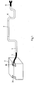
- Fig. 1 shows a battery 2, in particular a starter battery.
- Battery poles 2a, 2b for connecting consumers are provided on the battery 2.
- the battery pole 2 b is preferably the B + pole of the battery 2.
- a connection element 4, in particular a flexible cable, is attached to the battery pole 2 b.
- the connection element 4 has a battery terminal which is screwed to the battery pole 2b.
- the motor vehicle battery line is formed from the parts 6, 8 and 10.
- the connection element 4 is integrally connected to the part 6.
- the part 6 has bends which are shaped such that the part 6 fits into the installation space of the battery lead. The bends on the part 6 are type-specific shaped so that they meet the requirements of motor vehicle manufacturers.
- Part 6 is connected to part 8.
- the part 8 is preferably straight, especially if it is arranged in the center console or on the underfloor of the motor vehicle. On the part 8, a part 10 is arranged, which again has bends. At the part 10 is a connection element 12 for connection to an electrical load, in particular a consumer or a generator, for example, a generator, such as an alternator connected.
- an electrical load in particular a consumer or a generator, for example, a generator, such as an alternator connected.
- the consisting of the parts 6, 8 and 10 motor vehicle battery cable is assembled only shortly before assembly.
- the parts 6, 8, 10 are made separately.
- the part 6 and the part 10 is formed from an aluminum strip.
- the parts 6, 10 are formed from a annealed aluminum strip. This aluminum strip is fed to an extruder and an insulating layer is applied to the parts 6, 10.
- the parts 6, 10 are formed in bending devices according to the space requirements of the motor vehicle manufacturer type-specific. The bends are preferably only in one plane.
- the part 8 is made separately from the parts 6, 10. Since the part 8 is preferably straight, bending is not necessary.
- the part 8 is preferably stiffer than the parts 6, 10, for example made of work-hardened aluminum.
- the parts 6, 8, 10 are transported to a sequencer after production.
- a battery line is formed from parts 6, 8, 10 after receipt of the order.
- a shape-adapted part 6 and a shape-adapted part 10 corresponding to the type of vehicle in which the battery line is to be installed are used.
- To the part 6, the part 8 is welded. In particular rotary friction welding or multi-orbital welding is used.
- the part 8 has a length that meets the requirements of the type of vehicle in which the battery cable is to be installed.
- To the part 8, the part 10 is also welded.
- the resulting battery conductor is from the sequencer merely spent on the assembly line and mounted there. Due to the fact that the battery ladder only has to be mounted shortly before installation, it has low requirements for logistics. It is not necessary to transport meter-long battery strings over long distances. According to the invention, only parts 6-10 have to be transported and connected to each other shortly before assembly.
- the battery line according to the invention offers a simple solution concept.
- a part of a battery lead from the parts 14, 18, 20 is formed.
- the part 14 is bent in the plane parallel to the longitudinal axis 16 of the part 14.
- the arc 14a is a bend in the plane of the longitudinal axis 16.
- the part 18 is connected to the part 14. In the bend 18 a, the part 18 is bent so that it protrudes from the plane of the longitudinal axis 16 of the part 14.
- the connection 22 it is possible to form the conductor 14 so that only bends 14 a in the plane of the longitudinal axis 16 are present.
- the conductor 18 has bends 18 a, 18 b, which are formed perpendicular to the longitudinal axis of the conductor 18.
- the part 18 is connected at the connection point 24 with the part 20.
- the part 20 is again shaped so that the bend 20a lies in the plane parallel to the longitudinal axis 16 of the conductor 14.
- connection 22, 24 between the parts 14, 18, 20 it is possible to provide a battery conductor with bends in different spatial directions available. It is not necessary to provide elaborate production methods available, but the individual parts 14, 18, 20 can be assembled and must be connected to each other shortly before mounting in the vehicle. This minimizes the manufacturing costs and the transport costs.
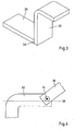
- Fig. 3 shows two parts 26, 28 of a battery cable, which are connected to each other at the connection point 30.
- the part 28 is arranged with one of its side surfaces on the end face of the part 26.
- a right-angled bend having a radius of almost 0 ° can be produced in the connection point 30.
- Such a bend would not be possible with a one-piece battery ladder.
- the illustrated connection, the battery cable according to the invention can also be adapted to extreme space requirements.
- Fig. 4 shows two parts 32, 36 of a motor vehicle battery line.
- the parts 32, 36 are integrally connected to one another at the connection point 34.
- the part 36 is arranged at an angle to the longitudinal axis 38 of the part 32.
- the joint 34 is preferably made by a rotary friction welding connection.
- the modular construction of the motor vehicle battery line according to the invention makes it possible to produce battery lines with a wide variety of shapes.
- the individual parts of the motor vehicle battery can be easily transported and assembled as needed.
- the straight lines of almost 0 ° and right-angled bends can be produced with the aid of the modular construction of the motor vehicle battery cable.
Landscapes
- Chemical Kinetics & Catalysis (AREA)
- Electrochemistry (AREA)
- General Chemical & Material Sciences (AREA)
- Chemical & Material Sciences (AREA)
- Connection Of Batteries Or Terminals (AREA)
- Battery Mounting, Suspending (AREA)
- Arrangement Or Mounting Of Propulsion Units For Vehicles (AREA)
- Body Structure For Vehicles (AREA)
- Insulated Conductors (AREA)
- Multi-Conductor Connections (AREA)
- Coupling Device And Connection With Printed Circuit (AREA)
- Primary Cells (AREA)
- Secondary Cells (AREA)
Description
- Die Erfindung betrifft ein Verfahren zur Herstellung eines Kraftfahrzeugbatterieleiters.
- Batterieleiter, insbesondere B+ Leiter, werden in herkömmlicher Weise als Rundleiter ausgeführt. In vielen Automobilen ist es üblich, die Batterie im Heck des Fahrzeugs anzuordnen, da dort der notwendige Bauraum zur Verfügung steht und dieser im Motorraum eingespart wird. In diesen Fällen ist es notwendig, dass die B+ Leitungen von der Batterie im Heck des Fahrzeugs zu dem Generator im Motorraum geführt wird. Bei der Verwendung von Rundleitern wird dies in herkömmlicherweise durch das Verlegen des Rundleiters in Kabelkanälen gelöst. Bauraumanforderungen bedingen dabei enge Radien. Die Batterieleitung wird angepasst an den Bauraum durch die Karosse des Fahrzeugs geführt. Dabei ergeben sich besondere Formanforderungen insbesondere im Heckbereich als auch im Motorraumbereich, da das Batteriekabel an bauteilbedingte Anforderungen an den Kabelweg angepasst werden muss. Zwischen dem Heckbereich und dem Motorraum verläuft das Batteriekabel häufig durch die Mittelkonsole oder am Unterflur des Fahrzeugs.
- In letzter Zeit setzen sich Flachleiter als Batteriekabel, insbesondere als B+ Kabel, durch. Die Verwendung von Flachleitern hat den Vorteil, dass bei gleichem Leiterquerschnitt geringere Bauraumanforderungen notwendig sind. Außerdem können Flachleiter aus Aluminium mit größeren Querschnitten verlegt werden, so dass stets eine notwendige Stromtragfähigkeit gewährleistet ist. Durch die Vergrößerung des Leiterquerschnitts ergeben sich bei der Verwendung von Aluminium auch keine Probleme hinsichtlich des Innenwiderstandes des Batteriekabels.
- Es hat sich jedoch gezeigt, dass die aus Flachleitern gebildeten Batteriestränge dann unhandlich sind, wenn kleine Biegeradien erforderlich sind. Aufgrund der Bauraumanforderungen müssen die Batteriestränge formangepasst sein, d. h., sie müssen so geformt sein, dass sie an die Karosse angepasst sind und in dem vorgesehenen Bauraum verbaut werden können. Aufgrund von Bauraumanforderungen kommt es vor, dass die Flachleiter in alle drei Raumrichtungen gebogen sein müssen, um den Anforderungen an den zur Verfügung stehenden Bauraum zu entsprechen. Hierbei kommt es jedoch dazu, dass enge Radien erfordert werden. Die Batterieleiter müssen, um an den vorhandenen Bauraum angepasst zu sein, teilweise mit Radien von nahe 0 cm gebogen werden. Dies führt jedoch zu Problemen bei der Konfektionierung der Batterieleiter.
- Darüber hinaus können B+ Leitungen mehrere Meter lang sein. So verläuft die B+ Leitung beispielsweise bei der Heckverlegung - die Batterie ist im Heck verbaut - entlang der gesamten Länge der Karosse bis in den Motorraum, wobei jeweils im Heckbereich als auch im Motorraumbereich eine Vielzahl von Biegungen vorgesehen sind. Jedoch im Bereich der Unterfluranordnung verläuft der Batterieleiter im Wesentlichen gerade. Diese langen Batterieleiter sind problematisch hinsichtlich der Logistik. Bei heutiger Serienfertigung von Automobilen wird eine Lieferung just in time verlangt. Zusätzlich werden auf ein und derselben Fertigungsstraße verschiedene Varianten eines Fahrzeugsmodells hergestellt. Die verschiedenen Varianten erfordern jedoch häufig verschiedenartige Batterieleitungen. Um diese zeitgerecht an dem Montageband zur Verfügung zu stellen, ist eine aufwendige Lagerhaltung notwendig, insbesondere wenn der Transport der langen Batterieleitungen aufwendig ist.
- Aus den
WO 2006/082238 A ist ein Verfahren zur Herstellung einen Kraftfahrzeugbatterieleitung bekannt. - Aus der
WO 2007/134634 A der selben Anmelderin ist eine Kabeldurchführung bekannt, bei der zwei Anschlussfahnen im Bereich eines Versatzes miteinander verbunden sind. Der Versatz dient der Kabeldurchführung durch eine Öffnung in einem Karosserieblech.WO 2007/134634 A fällt unter Artikel 54(3) EPÜ. - Aus den vorgenannten Problemen ergibt sich die erfindungsgemäße Aufgabe, eine Kraftfahrzeugbatterieleitung zur Verfügung zu stellen, die komplexen Bauraumanforderungen genügt und gleichzeitig leicht handhabbar ist.
- Diese Aufgabe wird erfindungsgemäß durch ein Verfahren nach Anspruch 1 gelöst.
- Erfindungsgemäß ist erkannt worden, dass es nicht zwingend notwendig ist, den Batterieleiter einstückig herzustellen und am Montageband zur Verfügung zu stellen. Vielmehr reicht es aus, den Flachleiter erst kurz vor der Montage zu montieren. Für die Logistik ist es vorteilhaft, dass der Flachleiter mehrstückig gebildet ist. Durch den modularen Aufbau der Batterieleitung, bei dem eine Mehrzahl von Teilen die gesamte Batterieleitung bilden können, ist es möglich, auf unterschiedlichste Modellanforderungen reagieren zu können. Beispielsweise ist es denkbar, dass der am Unterboden oder in der Mittelkonsole im Innenraum verlaufende Strang des Batterieleiters gerade gebildet ist und lediglich unterschiedliche Längen hat und die im Heck bzw. im Motorraum verbauten Teile des Batterieleiters verschiedenartig geformt sind, um den Anforderungen an den Bauraum bei verschiedenartigen Modellen oder Modellvarianten genüge zu tun.
- Die Modularität des Batterieleiters ermöglicht es, in einem nahe der Montage gelegenen Sequenzierwerk Einzelteile vorzuhalten, welche entsprechend den Anforderungen an das zur Zeit zu fertigende Fahrzeug genügen. So ist es möglich, kurz vor der Montage entsprechende Modellinformationen zur Verfügung zu stellen, woraufhin die Einzelteile der Kraftfahrzeugbatterie miteinander verbunden werden und an die Montagestraße verbracht werden.
- Es hat sich gezeigt, dass eine vorteilhafte Verbindung der Teile des Flachleiters formschlüssig und/oder kraftschlüssig und/oder stoffschlüssig gebildet sein kann. Insbesondere bei Flachleitern aus Aluminium ist ein Stoffschluss bevorzugt. In diesem Falle kann der Verbindungswiderstand niedrig gehalten werden, da die isolierenden Aluminiumoxidschichten vermieden werden können. Insbesondere bei Batterieleitern aus Buntmetall, beispielsweise Kupfer oder Messing, reicht ein Formschluss oder Kraftschluss aus, um eine genügend hohe Leitfähigkeit des Übergangs zu gewährleisten. Insbesondere bei Verbindungen zwischen Aluminium und Kupfer muss darauf geachtet werden, dass diese vor Umwelteinflüssen geschützt werden, so dass an den Verbindungen der Teile bevorzugt Schrumpfschläuche vorgesehen sind. Andere Isolationen, beispielsweise durch Umschäumen oder Umspritzen, sind ebenfalls möglich.
- Besonders vorteilhaft lassen sich die Teile des Flachleiters miteinander verbinden, indem sie verschweißt werden. Es hat sich gezeigt, dass Punktverschweißen mittels Reibschweißen besonders vorteilhaft ist, jedoch lassen sich die Teile auch mittels Multi-Orbital-Schweißen miteinander fügen.
- Biegungen in einer Ebene lassen sich bei einem Flachleiter leicht herstellen. Jedoch wird die Herstellung problematisch, sobald eine zweite Biegung in einer anderen Ebene notwendig wird. Daher wird vorgeschlagen, dass der erste Teil des Flachleiters in einer Ebene parallel zur Längsachse des Flachleiters gebogen ist. Bevorzugt ist der Flachleiter nur in der einen Ebene parallel zur Längsachse des Flachleiters gebogen. Dies hat den Vorteil, dass für den Fall, dass der Bauraum einen ebenen Verlauf des Flachleiters verlangt, das entsprechende Teil an den Bauraum angepasst werden kann.
- Sobald Biegungen in einer Ebene senkrecht zur Längsachse des Flachleiters notwendig werden, kann ein zweiter Teil des Flachleiters dementsprechend gebogen sein. Durch Verbindung des in der Ebene parallel zur Längsachse gebogenen Teils des Flachleiters mit dem in der Ebene senkrecht zur Längsachse des Flachleiters gebogenen Teils des Flachleiters ist es möglich, Bauraumanforderungen zu genügen, die Biegungen in allen drei Raumrichtungen erfordern. Die Herstellung jedes einzelnen Teils bleibt jedoch kostengünstig.
- Ein formangepasster Teil des Flachleiters ist dazu geeignet, derart geformt zu sein, dass er sich an die Bauraumanforderungen anpasst. Der Flachleiter ist so geformt, dass er an den zur Verfügung gestellten Bauraum angepasst ist. Biegungen werden so geformt, dass sie den Bauraumanforderungen genügen.
- Um bei der Herstellung mit geringem Kraftaufwand gebogen werden zu können, wird vorgeschlagen, dass zumindest ein Teil des Flachleiters aus Aluminium, insbesondere weichgeglühtem Aluminium gebildet ist. Da die Teile des Flachleiters an unterschiedlichen Stellen im Fahrzeug verbaut sind, kann es vorteilhaft sein, wenn ein erster Teil des Flachleiters weichgeglüht ist und ein zweiter Teil des Flachleiters aus verfestigtem, insbesondere kalt verfestigtem Aluminium gebildet ist. Beispielsweise kann der Teil de Flachleiters, der am Unterboden oder in der Mittelkonsole verlegt ist, aus verfestigtem Aluminium gebildet sein und ein anderer Teil des Flachleiters, der eine Vielzahl von Biegungen aufweisen kann, da er formangepasst ist, aus weichgeglühtem Aluminium gebildet sein. Dies ergibt in Kombination eine hohe Steifigkeit als auch eine leichte Herstellbarkeit.
- Um den Teil des Flachleiters, der formangepasst ist, leicht verformen zu können, wir vorgeschlagen, dass zumindest der Teil des Flachleiters steifelastisch ist. Steifelastisch bedeutet, dass der Flachleiter verformbar ist, jedoch in der Form nach dem Verformen verbleibt.
- Um enge Winkel im Verlauf des Batterieleiters zur Verfügung zu stellen, wird vorgeschlagen, dass der zweite Teil mit des Flachleiters winklig zur Längsachse des ersten Teils dessen Teil verbunden ist. Hierdurch können Bögen, insbesondere senkrechte Winkel in dem Batterieleiter zur Verfügung gestellt werden. Es hat sich gezeigt, dass bei engen Radien die Isolierung, die den Flachleiter umschließt, sich aufwölbt. Um dieses Aufwölben zu verhindern, sind bei herkömmlichen Biegeverfahren zusätzliche Maßnahmen, wie beispielsweise Erhitzen des Isolators, notwendig. Wird gemäß des vorteilhaften Ausführungsbeispiels der Teil des Flachleiters winklig zur Längsachse des anderen Teils verbunden, können enge Radien zur Verfügung gestellt werden, ohne aufwendige Biegeverfahren zu verwenden.
- Um den Batterieleiter senkrecht zur Längsachse eines Teils führen zu können, wird vorgeschlagen, dass der zweite Teil des Flachleiters mit einer seiner Seitenflächen mit der Stirnfläche des ersten Teils des Flachleiters verbunden ist. Dadurch ist es möglich, Biegungen zur Verfügung zu stellen, die senkrecht zur Längsachse eines ersten Teils verlaufen.
- Weitere Vorteile ergeben sich aus den nachgeordneten Ansprüchen.
- Nachfolgend wird die Erfindung anhand einer Ausführungsbeispiele zeigenden Zeichnung näher erläutert. In der Zeichnung zeigen:
- Fig. 1
- eine erste Anordnung mit einer erfindungsgemäßen Kraftfahrzeugbatterieleitung;
- Fig. 2
- eine Ansicht einer Kraftfahrzeugbatterieleitung mit verschiedenen Teilen und Biegungen;
- Fig. 3
- eine Ansicht einer Kraftfahrzeugbatterieleitung mit einem an einer Stirnseite angeordnetem Teil:
- Fig. 4
- eine Draufsicht auf eine winklige Verbindung zwischen Teilen einer Kraftfahrzeugbatterieleitung.
-
Fig. 1 zeigt eine Batterie 2, insbesondere eine Starterbatterie. An der Batterie 2 sind Batteriepole 2a, 2b zum Anschluss von Verbrauchern vorgesehen. Der Batteriepol 2b ist bevorzugt der B+ Pol der Batterie 2. An dem Batteriepol 2b ist ein Anschlusselement 4, insbesondere ein flexibles Kabel befestigt. Das Anschlusselement 4 weist eine Batterieklemme auf, die an dem Batteriepol 2b verschraubt ist. Die Kraftfahrzeugbatterieleitung ist aus den Teilen 6, 8 und 10 gebildet. Wie zu erkennen ist, ist an dem Teil 6 das Anschlusselement 4 stoffschlüssig verbunden. Das Teil 6 weist Biegungen auf, die derart geformt sind, dass der Teil 6 in den Bauraum der Batterieleitung passt. Die Biegungen an dem Teil 6 sind typspezifisch so geformt, dass diese den Anforderungen der Kraftfahrzeughersteller genügen. Mit dem Teil 6 ist das Teil 8 verbunden. Das Teil 8 ist bevorzugt gerade, insbesondere wenn es in der Mittelkonsole oder am Unterflur des Kraftfahrzeugs angeordnet ist. An dem Teil 8 ist ein Teil 10 angeordnet, welches erneut Biegungen aufweist. An dem Teil 10 ist ein Anschlusselement 12 zum Anschluss an einen elektrischen Verbraucher, insbesondere einen Verbraucher oder einen Erzeuger, beispielsweise einen Generator, wie eine Lichtmaschine angeschlossen. - Die aus den Teilen 6, 8 und 10 bestehende Kraftfahrzeugbatterieleitung wird erst kurz vor der Montage zusammengebaut. Zunächst werden die Teile 6, 8, 10 getrennt voneinander hergestellt. Hierbei wird das Teil 6 und das Teil 10 aus einem Aluminiumband geformt. Es ist beispielsweise möglich, dass die Teile 6, 10 aus einem weichgeglühtem Aluminiumband geformt sind. Dieses Aluminiumband wird einem Extruder zugeführt und eine Isolationsschicht wird auf die Teile 6, 10 aufgebracht. Danach werden die Teile 6, 10 in Biegevorrichtungen entsprechend den Bauraumanforderungen der Kraftfahrzeughersteller typspezifisch geformt. Die Biegungen sind bevorzugt lediglich in einer Ebene.
- Das Teil 8 wird getrennt von den Teilen 6, 10 hergestellt. Da das Teil 8 bevorzugt gerade ist, ist ein Biegen nicht notwendig. Das Teil 8 ist bevorzugt steifer als die Teile 6, 10, beispielsweise aus kaltverfestigtem Aluminium hergestellt.
- Die Teile 6, 8, 10 werden nach der Herstellung zu einem Sequenzierwerk transportiert. In dem Sequenzierwerk wird nach Auftragseingang eine Batterieleitung aus den Teilen 6, 8, 10 geformt. Hierbei wird entsprechend des Auftrags ein formangepasstes Teil 6 und ein formangepasstes Teil 10 entsprechend dem Fahrzeugtyp, in den die Batterieleitung eingebaut werden soll, verwendet. An das Teil 6 wird das Teil 8 angeschweißt. Hierbei kommt insbesondere Rotationsreibschweißen oder Multi-Orbital-Schweißen zum Einsatz. Das Teil 8 hat eine Länge, die den Anforderungen des Typs des Fahrzeugs entspricht, in welches die Batterieleitung eingebaut werden soll. An das Teil 8 wird das Teil 10 ebenfalls verschweißt. Der so entstandene Batterieleiter wird von dem Sequenzierwerk lediglich an das Montageband verbracht und dort montiert. Dadurch, dass der Batterieleiter erst kurz vor der Montage montiert werden muss, hat er geringe Anforderungen an die Logistik. Es ist nicht notwendig, meterlange Batteriestränge über große Entfernung zu transportieren. Erfindungsgemäß müssen lediglich die Teile 6-10 transportiert werden und erst kurz vor der Montage miteinander verbunden werden.
- Wie bereits erläutert, werden die Anforderungen an den verfügbaren Bauraum immer strenger, d.h., dass Batterieleitungen mit immer engeren Winkeln und Biegungen hergestellt werden müssen, um in den nur knapp bemessenen Bauraum zu passen. Um Biegungen in verschiedenen Ebenen zur Verfügung zu stellen, bietet die erfindungsgemäße Batterieleitung ein einfaches Lösungskonzept. Wie in der
Figur 2 dargestellt ist, ist ein Teil einer Batterieleitung aus den Teilen 14, 18, 20 geformt. Das Teil 14 ist in der Ebene parallel zur Längsachse 16 des Teils 14 gebogen. Der Bogen 14a ist eine Biegung in der Ebene der Längsachse 16. An der Verbindungsstelle 22 ist das Teil 18 mit dem Teil 14 verbunden. In der Biegung 18a ist das Teil 18 so gebogen, dass es aus der Ebene der Längsachse 16 des Teils 14 herausragt. Einen Batterieleiter mit den Biegungen 14a, 18a, die jeweils in unterschiedliche Ebenen abzweigen, wäre in herkömmlicher Weise aufwendig herzustellen. Durch die Verbindung 22 ist es möglich, den Leiter 14 so zu formen, dass lediglich Biegungen 14a in der Ebene der Längsachse 16 vorhanden sind. Der Leiter 18 hat Biegungen 18a, 18b, die senkrecht zur Längsachse des Leiters 18 gebildet sind. Um erneut eine Biegung 20a in einer Ebene parallel zur Längsachse 16 zu ermöglichen, ist das Teil 18 an der Verbindungsstelle 24 mit dem Teil 20 verbunden. Das Teil 20 ist erneut so geformt, dass die Biegung 20a in der Ebene parallel zur Längsachse 16 des Leiters 14 liegt. - Durch die Verbindungen 22, 24 zwischen den Teilen 14, 18, 20, ist es möglich, einen Batterieleiter mit Biegungen in verschiednen Raumrichtungen zur Verfügung zu stellen. Es ist nicht notwendig, aufwendige Herstellungsverfahren zur Verfügung zu stellen, sondern die einzelnen Teile 14, 18, 20 können konfektioniert werden und müssen erst kurz vor der Montage in das Kraftfahrzeug miteinander verbunden werden. Dies minimiert den Herstellungsaufwand und die Transportkosten.
-
Fig. 3 zeigt zwei Teile 26, 28 einer Batterieleitung, die an der Verbindungsstelle 30 miteinander verbunden sind. Wie in derFigur 3 dargestellt, ist das Teil 28 mit einer seiner Seitenflächen auf der Stirnfläche des Teils 26 angeordnet. Durch die Anordnung des Teils 28 auf der Stirnfläche des Teils 26 lässt sich in der Verbindungsstelle 30 eine rechtwinklige Biegung mit einem Radius von nahezu 0° herstellen. Eine solche Biegung wäre mit einem einstückigem Batterieleiter nicht herstellbar. Durch die dargestellte Verbindung lässt sich die erfindungsgemäße Batterieleitung auch an extreme Bauraumanforderungen anpassen. -
Fig. 4 zeigt zwei Teile 32, 36 einer Kraftfahrzeugbatterieleitung. Die Teile 32, 36 sind an der Verbindungsstelle 34 miteinander stoffschlüssig verbunden. Das Teil 36 ist winklig zu der Längsachse 38 des Teils 32 angeordnet. Die Verbindungsstelle 34 ist vorzugsweise durch eine Rotationsreibschweißverbindung hergestellt. - Durch den erfindungsgemäßen modularen Aufbau der Kraftfahrzeugbatterieleitung lassen sich Batterieleitungen mit den verschiedensten Formen herstellen. Die einzelnen Teile der Kraftfahrzeugbatterie lassen sich leicht transportieren und bedarfsgerecht konfektionieren. Die Geraden von nahezu 0° und rechtwinklige Biegungen lassen sich mit Hilfe des modularen Aufbaus der Kraftfahrzeugbatterieleitung herstellen.
Claims (8)
- Verfahren zur Herstellung einer Kraftfahrzeugbatterieleitung, bei dem- in einem ersten Bearbeitungsschritt zumindest zwei Teile - eines Flachleiters der Batterieleitung aus Aluminium oder Buntmetall gebildet werden,- in einem zweiten Bearbeitungsschritt ein erster Teil der genannten Teile gebogen wird, und- in einem dritten Bearbeitungsschritt zumindest die genannten zwei Teile im Verlauf des Flachleiters miteinander formschlüssig und/oder Kraftschlüssig und/oder Stoffschlüssig verbunden werden.
- Verfahren nach einem der vorangehenden Ansprüche, dadurch gekennzeichnet, dass die ersten beiden Bearbeitungsschritte in einer ersten Fertigungshalle vorgenommen werden, dass die Teile zu einer Sequenzfertigung geliefert wird, und dass erst in der Sequenzfertigung der erste Teil mit dem zweiten Teil verbunden wird.
- Verfahren nach einem der vorangehenden Ansprüche, dadurch gekennzeichnet, dass der zweite Teil winklig zur Längsachse des ersten Teils mit dem ersten Teil verbunden wird.
- Verfahren nach einem der vorangehenden Ansprüche, dadurch gekennzeichet, dass der zweite Teil winklig in einer Ebene senkrecht zur Längsachse des ersten Teils mit dem ersten Teil verbunden wird.
- Verfahren nach Anspruch 1, dadurch gekennzeichnet, dass in dem zweiten Bearbeitungsschritt der erste Teil in einer Ebene parallel zu seiner Längsachse gebogen wird.
- Verfahren nach einem der vorangehenden Ansprüche, dadurch gekennzeichnet, dass ein dem zweiten Bearbeitungsschritt ein zweiter Teil in einer Ebene senkrecht zu seiner Längsachse gebogen wird.
- Verfahren nach einem der vorangehenden Ansprüche, dadurch gekennzeichnet, dass der zweite Flachleiter stoffschlüssig mit dem ersten Flachleiter verbunden wird.
- Verfahren nach einem der vorangehenden Ansprüche, dadurch gekennzeichnet, dass der zweite Flachleiter mit dem ersten Flachleiter mittels Reibschweißen punktverschweißt ist.
Priority Applications (3)
| Application Number | Priority Date | Filing Date | Title |
|---|---|---|---|
| EP11164443.1A EP2343220B1 (de) | 2006-10-24 | 2007-10-19 | Batterieleitung |
| EP11164398.7A EP2343219B1 (de) | 2006-10-24 | 2007-10-19 | Batterieleitung |
| EP09170629.1A EP2133242B1 (de) | 2006-10-24 | 2007-10-19 | Batterieleitung |
Applications Claiming Priority (2)
| Application Number | Priority Date | Filing Date | Title |
|---|---|---|---|
| DE102006050705A DE102006050705B4 (de) | 2006-10-24 | 2006-10-24 | Batterieleitung |
| PCT/EP2007/061203 WO2008049788A1 (de) | 2006-10-24 | 2007-10-19 | Batterieleitung |
Related Child Applications (4)
| Application Number | Title | Priority Date | Filing Date |
|---|---|---|---|
| EP11164443.1A Division EP2343220B1 (de) | 2006-10-24 | 2007-10-19 | Batterieleitung |
| EP09170629.1A Division EP2133242B1 (de) | 2006-10-24 | 2007-10-19 | Batterieleitung |
| EP11164398.7A Division EP2343219B1 (de) | 2006-10-24 | 2007-10-19 | Batterieleitung |
| EP09170629.1 Division-Into | 2009-09-18 |
Publications (2)
| Publication Number | Publication Date |
|---|---|
| EP1989080A1 EP1989080A1 (de) | 2008-11-12 |
| EP1989080B1 true EP1989080B1 (de) | 2010-06-02 |
Family
ID=38819756
Family Applications (4)
| Application Number | Title | Priority Date | Filing Date |
|---|---|---|---|
| EP11164443.1A Not-in-force EP2343220B1 (de) | 2006-10-24 | 2007-10-19 | Batterieleitung |
| EP09170629.1A Active EP2133242B1 (de) | 2006-10-24 | 2007-10-19 | Batterieleitung |
| EP07821567A Active EP1989080B1 (de) | 2006-10-24 | 2007-10-19 | Batterieleitung |
| EP11164398.7A Not-in-force EP2343219B1 (de) | 2006-10-24 | 2007-10-19 | Batterieleitung |
Family Applications Before (2)
| Application Number | Title | Priority Date | Filing Date |
|---|---|---|---|
| EP11164443.1A Not-in-force EP2343220B1 (de) | 2006-10-24 | 2007-10-19 | Batterieleitung |
| EP09170629.1A Active EP2133242B1 (de) | 2006-10-24 | 2007-10-19 | Batterieleitung |
Family Applications After (1)
| Application Number | Title | Priority Date | Filing Date |
|---|---|---|---|
| EP11164398.7A Not-in-force EP2343219B1 (de) | 2006-10-24 | 2007-10-19 | Batterieleitung |
Country Status (8)
| Country | Link |
|---|---|
| US (1) | US9177695B2 (de) |
| EP (4) | EP2343220B1 (de) |
| CN (1) | CN101448681B (de) |
| AT (1) | ATE469792T1 (de) |
| DE (2) | DE102006050705B4 (de) |
| ES (3) | ES2537433T3 (de) |
| PT (1) | PT1989080E (de) |
| WO (1) | WO2008049788A1 (de) |
Cited By (1)
| Publication number | Priority date | Publication date | Assignee | Title |
|---|---|---|---|---|
| DE102022201987A1 (de) | 2022-02-25 | 2023-08-31 | Leoni Bordnetz-Systeme Gmbh | Stromschienen-Anordnung zur elektrischen Leistungsversorgung einer elektrischen Komponente sowie Bordnetz eines Kraftfahrzeugs mit einer solchen Stromschienen-Anordnung |
Families Citing this family (23)
| Publication number | Priority date | Publication date | Assignee | Title |
|---|---|---|---|---|
| EP2441103B2 (de) | 2009-06-08 | 2018-09-12 | Auto-Kabel Management GmbH | Batteriezellenverbinder |
| DE102009032987A1 (de) | 2009-07-14 | 2011-01-27 | Eifelwerk Heinrich Stein Gmbh & Co Kg | Elektrische Leitung für Kraftfahrzeuge |
| DE102009058953A1 (de) * | 2009-12-18 | 2011-06-22 | Magna Steyr Fahrzeugtechnik Ag & Co Kg | Akkumulator-Modul |
| JP5938777B2 (ja) | 2010-07-12 | 2016-06-22 | 矢崎総業株式会社 | ワイヤハーネス、ワイヤハーネスと機器との搬送方法、及びワイヤハーネスによる機器間の接続方法 |
| DE102012203571C5 (de) * | 2012-03-07 | 2016-07-28 | Lisa Dräxlmaier GmbH | Verfahren zum plastischen Umformen mehrerer elektrisch leitender Schichten eines Flachleiters zu einer mehrdimensionalen Kontur sowie Vorrichtungen für dieses Verfahren |
| DE102012015350A1 (de) | 2012-08-06 | 2014-02-06 | Auto-Kabel Management Gmbh | Kraftfahrzeugenergieleitung mit einem Fremdstartstützpunkt |
| CN103273192A (zh) * | 2013-06-14 | 2013-09-04 | 云南驰宏锌锗股份有限公司 | 一种大面积锌电解阳极板焊接方法 |
| DE102014011180B4 (de) * | 2014-07-31 | 2020-09-03 | Auto-Kabel Management Gmbh | Elektrischer Flachleiter für Kraftfahrzeuge |
| FR3028658B1 (fr) * | 2014-11-17 | 2016-12-02 | Peugeot Citroen Automobiles Sa | Agencement de cable d'alimentation de batterie de vehicule |
| DE102015100384B4 (de) | 2015-01-13 | 2016-07-28 | Lisa Dräxlmaier GmbH | Verfahren zum Verbinden zweier Leitungskomponenten und resultierender Flachleiter |
| CN106558671B (zh) * | 2015-09-30 | 2019-11-22 | 比亚迪股份有限公司 | 用于动力电池的连接器、动力电池模组、动力电池包、汽车 |
| CN106558667B (zh) * | 2015-09-30 | 2019-06-21 | 比亚迪股份有限公司 | 动力电池的连接器、动力电池模组、动力电池包、汽车 |
| DE102017112097B3 (de) * | 2017-06-01 | 2018-07-12 | Lisa Dräxlmaier GmbH | VERFAHREN ZUM ANBRINGEN WENIGSTENS EINES ELEKTRISCHEN KONTAKTELEMENTS AN EINER ALUMINIUMSCHIENE FÜR EIN BORDNETZ EINES KRAFTFAHRZEUGS UND REIBSCHWEIßVERBINDUNG |
| DE102017114579B4 (de) * | 2017-06-29 | 2021-09-02 | Lisa Dräxlmaier GmbH | Verfahren zum handhaben einer flachleiteranordnung |
| CN109285633B (zh) * | 2017-07-21 | 2021-08-10 | 矢崎(中国)投资有限公司 | 利用金属芯线制造汇流排的方法以及汇流排 |
| JP7017440B2 (ja) * | 2018-03-07 | 2022-02-08 | 矢崎総業株式会社 | 電線の製造方法、及び、電線 |
| CN110557966B (zh) * | 2018-03-30 | 2021-06-25 | 古河电气工业株式会社 | 绝缘电线材料及其制造方法、以及线圈和电气/电子设备 |
| EP3780014A4 (de) * | 2018-03-30 | 2021-12-29 | Furukawa Electric Co., Ltd. | Isoliertes stromdrahtmaterial, verfahren zur herstellung eines isolierten stromdrahtmaterials, spule und elektrische/elektronische vorrichtung |
| DE102018217785A1 (de) * | 2018-10-17 | 2020-04-23 | Volkswagen Aktiengesellschaft | Verfahren zum Herstellen eines zwei- oder dreidimensional geformten Flachleiters aus Metall |
| DE102019118671A1 (de) * | 2019-07-10 | 2021-01-14 | Auto-Kabel Management Gmbh | Kraftfahrzeugenergieleitungsbaukasten sowie Verfahren zur Herstellung eines Kraftfahrzeugenergieleiters |
| DE102019130078A1 (de) | 2019-11-07 | 2021-05-12 | Auto-Kabel Management Gmbh | Kraftfahrzeugenergieleitung sowie ein Verfahren zum Biegen einer Kraftfahrzeugenergieleitung |
| DE102021201194A1 (de) | 2021-02-09 | 2022-08-11 | Volkswagen Aktiengesellschaft | Verfahren und Pressenwerkzeug zum Herstellen einer zwei- oder dreidimensional geformten Stromschiene mit unterschiedlichen Querschnitten |
| JP7405789B2 (ja) * | 2021-04-01 | 2023-12-26 | 矢崎総業株式会社 | 電線及びワイヤーハーネス |
Family Cites Families (42)
| Publication number | Priority date | Publication date | Assignee | Title |
|---|---|---|---|---|
| DE503154C (de) * | 1930-07-19 | Siemens Schuckertwerke Akt Ges | Verbindungsstelle fuer Leitungen aus Aluminium oder Aluminiumlegierungen | |
| DE421019C (de) | 1921-12-31 | 1925-11-05 | Geidner Metallwaren Wilhelm | Aufsteckspindel mit Abschlussstoepsel zum Behandeln von Garnwickeln (Kreuz-, Sonnenoder Flyer-Spulen) mit kreisenden Fluessigkeiten oder Gasen fuer Faerbe- und Bleichzwecke |
| US1946862A (en) * | 1931-12-10 | 1934-02-13 | Jr Louis A Koch | Ground terminal |
| US3220891A (en) * | 1962-01-08 | 1965-11-30 | Aluminum Co Of America | Annealing sheet metal coils and product |
| US3512221A (en) * | 1969-04-07 | 1970-05-19 | Southwire Co | Aluminum alloy wire |
| US3688548A (en) * | 1969-06-03 | 1972-09-05 | Mitsubishi Aluminium | Apparatus for the manufacture of aluminum strip conductors |
| US3630725A (en) * | 1969-08-06 | 1971-12-28 | Southwire Co | Method of preparing an aluminum alloy |
| US3706955A (en) * | 1971-04-28 | 1972-12-19 | Amp Inc | Electrical cable having integral terminals |
| GB1413321A (en) | 1972-05-04 | 1975-11-12 | British Insulated Callenders | Electric cables |
| JPS5442340B2 (de) * | 1974-02-12 | 1979-12-13 | ||
| IT1030225B (it) * | 1975-02-27 | 1979-03-30 | Fiat Spa | Impianto elettrico in particolare per autoveicoli |
| DE2745189C2 (de) * | 1977-10-07 | 1983-01-05 | Heinrich Dr.-Ing. 5231 Eichelhardt Stein | Elektrischer Stromleiter zur Verbindung zwischen der Batterie und dem Anlasser bzw. der Masse von Verbrennungs-Kraftmaschinen in Kraftfahrzeugen |
| DE3913324A1 (de) * | 1989-04-22 | 1990-10-31 | Vaw Ver Aluminium Werke Ag | Aluminiumwalzhalbzeug und verfahren zu seiner herstellung |
| US5370028A (en) * | 1989-08-31 | 1994-12-06 | Karl Marbach Gmbh & Co. | Strip steel punching and indenting tool |
| DE4210202C2 (de) * | 1992-03-28 | 1994-05-05 | Temic Telefunken Kabelsatz Gmb | Batteriekabel |
| AU4231593A (en) * | 1992-05-14 | 1993-12-13 | Collier Aluminum, Inc. | Strip conductor for transformers |
| US5389002A (en) * | 1992-12-22 | 1995-02-14 | Nippondenso Co., Ltd. | Connector apparatus used for a flexible cable |
| JPH06200346A (ja) | 1993-01-05 | 1994-07-19 | Sky Alum Co Ltd | 成形性に優れた成形加工用アルミニウム合金およびその製造方法 |
| JP2942458B2 (ja) * | 1993-04-16 | 1999-08-30 | 住友電気工業株式会社 | フラットケーブル用導体の製造方法および製造設備 |
| US5912610A (en) * | 1993-12-20 | 1999-06-15 | United Defense, Lp | High energy inductor |
| US5530625A (en) * | 1994-09-07 | 1996-06-25 | Electro-Wire Products, Inc. | Electrical interface board including flat ribbon conductors positioned on edge |
| US5771966A (en) * | 1995-12-15 | 1998-06-30 | Jacoby; John | Folded conducting member heatsinks and method of making same |
| US6221185B1 (en) * | 1996-08-26 | 2001-04-24 | Michelin Kronprinz Werke Gmbh | Method for manufacturing components by critical formation of light metal strip |
| ATE199172T1 (de) * | 1998-10-01 | 2001-02-15 | Lamitref Ind N V | Copper cathode starting sheets for copper electrolysis and manufacture thereof |
| FR2784635B1 (fr) * | 1998-10-15 | 2000-12-29 | Framatome Connectors Int | Dispositif de cablage pour vehicules a moteur ou similaires |
| ES1044129Y (es) * | 1999-08-10 | 2000-08-16 | Mecanismos Aux Ind | Dispositivo para la fijacion de componentes electricos. |
| DE10001632A1 (de) * | 2000-01-17 | 2001-08-02 | Harting Automotive Gmbh & Co | Leitungsunterbrecher |
| US6488532B2 (en) * | 2000-08-29 | 2002-12-03 | Alfiero Balzano | Charger-to-battery connector |
| KR100890715B1 (ko) * | 2000-11-01 | 2009-03-27 | 소니 가부시끼 가이샤 | 전지, 전지의 제조 방법, 용접물의 제조 방법 및 페데스탈 |
| US6479438B2 (en) * | 2001-01-04 | 2002-11-12 | Isp Investments Inc. | Gel inhibited liquid carrier for a biocide containing a carbodiimide and an emulsifier mixture |
| KR100434617B1 (ko) * | 2001-03-01 | 2004-06-04 | 후루카와 덴끼고교 가부시키가이샤 | 배전어셈블리 |
| DE10116636C2 (de) * | 2001-04-04 | 2003-04-03 | Vaw Ver Aluminium Werke Ag | Verfahren zur Herstellung von AIMn-Bändern oder Blechen |
| DE10152684A1 (de) * | 2001-10-19 | 2003-04-30 | Vb Autobatterie Gmbh | Elektrischer Akkumulator |
| DE50201563D1 (de) | 2002-03-27 | 2004-12-23 | Nexans | Elektrische Flachleiter-Bandleitung |
| JP2004298947A (ja) | 2003-03-31 | 2004-10-28 | Kobe Steel Ltd | 印刷版支持体用アルミニウム板の巻取制御方法及びその巻取制御装置並びにその巻取制御プログラム |
| DE102004007875B3 (de) * | 2004-02-17 | 2005-09-15 | Carl Freudenberg Kg | Dreidimensional geformtes Flachkabel |
| US7182825B2 (en) * | 2004-02-19 | 2007-02-27 | Alcoa Inc. | In-line method of making heat-treated and annealed aluminum alloy sheet |
| FR2867317B1 (fr) | 2004-03-04 | 2006-05-26 | Valeo Electronique Sys Liaison | Dispositif de support et de guidage de conducteurs optiques, pneumatiques, hydrauliques ou electriques |
| EP2662866B1 (de) * | 2005-02-03 | 2016-02-03 | Auto-Kabel Management GmbH | Mehrschichtiger elektrischer Flachbandleiter |
| JP2007157382A (ja) * | 2005-12-01 | 2007-06-21 | Matsushita Battery Industrial Co Ltd | 組電池 |
| WO2007134634A1 (de) | 2006-05-18 | 2007-11-29 | Auto Kabel Managementgesellschaft Mbh | Stromprofil für kabeldurchführungen |
| DE102006062850B4 (de) * | 2006-07-07 | 2013-03-28 | Auto-Kabel Managementgesellschaft Mbh | Elektrisches Kontaktelement |
-
2006
- 2006-10-24 DE DE102006050705A patent/DE102006050705B4/de active Active
-
2007
- 2007-10-19 CN CN2007800116595A patent/CN101448681B/zh active Active
- 2007-10-19 ES ES11164398.7T patent/ES2537433T3/es active Active
- 2007-10-19 EP EP11164443.1A patent/EP2343220B1/de not_active Not-in-force
- 2007-10-19 DE DE502007004008T patent/DE502007004008D1/de active Active
- 2007-10-19 WO PCT/EP2007/061203 patent/WO2008049788A1/de not_active Ceased
- 2007-10-19 US US12/282,724 patent/US9177695B2/en active Active
- 2007-10-19 EP EP09170629.1A patent/EP2133242B1/de active Active
- 2007-10-19 EP EP07821567A patent/EP1989080B1/de active Active
- 2007-10-19 ES ES11164443.1T patent/ES2564642T3/es active Active
- 2007-10-19 AT AT07821567T patent/ATE469792T1/de active
- 2007-10-19 ES ES09170629.1T patent/ES2517892T3/es active Active
- 2007-10-19 PT PT07821567T patent/PT1989080E/pt unknown
- 2007-10-19 EP EP11164398.7A patent/EP2343219B1/de not_active Not-in-force
Cited By (1)
| Publication number | Priority date | Publication date | Assignee | Title |
|---|---|---|---|---|
| DE102022201987A1 (de) | 2022-02-25 | 2023-08-31 | Leoni Bordnetz-Systeme Gmbh | Stromschienen-Anordnung zur elektrischen Leistungsversorgung einer elektrischen Komponente sowie Bordnetz eines Kraftfahrzeugs mit einer solchen Stromschienen-Anordnung |
Also Published As
| Publication number | Publication date |
|---|---|
| WO2008049788A1 (de) | 2008-05-02 |
| ES2537433T3 (es) | 2015-06-08 |
| US9177695B2 (en) | 2015-11-03 |
| EP2133242A3 (de) | 2010-12-01 |
| ES2564642T3 (es) | 2016-03-28 |
| EP1989080A1 (de) | 2008-11-12 |
| DE502007004008D1 (de) | 2010-07-15 |
| US20090104514A1 (en) | 2009-04-23 |
| EP2133242A2 (de) | 2009-12-16 |
| DE102006050705A1 (de) | 2008-04-30 |
| EP2343219A1 (de) | 2011-07-13 |
| EP2343220B1 (de) | 2016-01-20 |
| PT1989080E (pt) | 2010-07-20 |
| DE102006050705B4 (de) | 2009-01-02 |
| EP2343219B1 (de) | 2015-03-18 |
| ATE469792T1 (de) | 2010-06-15 |
| EP2343220A1 (de) | 2011-07-13 |
| ES2517892T3 (es) | 2014-11-04 |
| CN101448681A (zh) | 2009-06-03 |
| EP2133242B1 (de) | 2014-09-10 |
| CN101448681B (zh) | 2011-11-23 |
Similar Documents
| Publication | Publication Date | Title |
|---|---|---|
| EP1989080B1 (de) | Batterieleitung | |
| EP2662866B1 (de) | Mehrschichtiger elektrischer Flachbandleiter | |
| DE102018214516B4 (de) | Fahrzeugschaltungsträgerkörper | |
| DE102008003332B4 (de) | Formstabiler Kabelstrang für die Motorraumverkabelung | |
| DE112015005781T5 (de) | Kraftfahrzeug-Stromversorgungsvorrichtung | |
| DE102006049604C5 (de) | Hochstromkabel für Fahrzeuge sowie Kabelkanal zum elektrisch isolierenden Aufnehmen eines solchen Hochstromkabels | |
| DE102017209871A1 (de) | Kabelbaum | |
| DE102012220940A1 (de) | Kabelbaum und Verfahren zur Herstellung desselben | |
| DE102016201431A1 (de) | Außenelement und Kabelbaum | |
| DE4115971A1 (de) | Stromversorgung fuer kraftfahrzeuge | |
| DE102006050709B3 (de) | Kraftfahrzeugbatterieleitung | |
| EP3878053B1 (de) | Verfahren zur herstellung eines anschlussteils für elektrische anlagen, anschlussteil sowie verbindung eines anschlussteils mit einem kabel | |
| EP1701362A2 (de) | Stromkabel | |
| DE102009032987A1 (de) | Elektrische Leitung für Kraftfahrzeuge | |
| EP2044598B1 (de) | Elektrisches kabel, insbesondere batteriekabel für kraftfahrzeuge | |
| DE102018110225B4 (de) | Leitungsanordnung für ein Bordnetz eines Kraftfahrzeugs | |
| DE102007061816A1 (de) | Potentialverteiler und Verfahren zur Herstellung eines Potentialverteilers | |
| DE102016111221B4 (de) | Strom- und/oder Datenschienenanordnung mit abgedichteten Abgangsknoten für ein Kraftfahrzeug | |
| DE3150220C2 (de) | Verzweigter Leitungsstrang, insbesondere Kabelbaum für Kraftfahrzeuge und Verfahren zu seiner Herstellung | |
| DE102008035741B4 (de) | Elektrisches Kabel, insbesondere Batteriekabel für Kraftfahrzeuge | |
| DE102024102384A1 (de) | Elektrische Stromleitung mit zwei Isolationsschichten; Batteriemodul; Leistungselektronik | |
| DE102025143715A1 (de) | Leitungssatz und Verfahren zur Bündelung von Leitungen | |
| DE102006062899B3 (de) | Hochstromkabel für Fahrzeuge sowie Kraftfahrzeug mit einem Batteriekabel | |
| WO2021121690A1 (de) | Elektrische anschlusskonsole für eine elektrische anlage sowie verfahren zur herstellung eines elektrischen abgriffs | |
| EP2621020A2 (de) | Elektrische Leitungsanordnung und Reibbelagsverschleißsensor |
Legal Events
| Date | Code | Title | Description |
|---|---|---|---|
| PUAI | Public reference made under article 153(3) epc to a published international application that has entered the european phase |
Free format text: ORIGINAL CODE: 0009012 |
|
| 17P | Request for examination filed |
Effective date: 20080908 |
|
| AK | Designated contracting states |
Kind code of ref document: A1 Designated state(s): AT BE BG CH CY CZ DE DK EE ES FI FR GB GR HU IE IS IT LI LT LU LV MC MT NL PL PT RO SE SI SK TR |
|
| AX | Request for extension of the european patent |
Extension state: AL BA HR MK RS |
|
| 17Q | First examination report despatched |
Effective date: 20090513 |
|
| DAX | Request for extension of the european patent (deleted) | ||
| GRAP | Despatch of communication of intention to grant a patent |
Free format text: ORIGINAL CODE: EPIDOSNIGR1 |
|
| GRAS | Grant fee paid |
Free format text: ORIGINAL CODE: EPIDOSNIGR3 |
|
| GRAA | (expected) grant |
Free format text: ORIGINAL CODE: 0009210 |
|
| AK | Designated contracting states |
Kind code of ref document: B1 Designated state(s): AT BE BG CH CY CZ DE DK EE ES FI FR GB GR HU IE IS IT LI LT LU LV MC MT NL PL PT RO SE SI SK TR |
|
| REG | Reference to a national code |
Ref country code: GB Ref legal event code: FG4D Free format text: NOT ENGLISH |
|
| REG | Reference to a national code |
Ref country code: CH Ref legal event code: EP |
|
| REG | Reference to a national code |
Ref country code: IE Ref legal event code: FG4D Free format text: LANGUAGE OF EP DOCUMENT: GERMAN |
|
| REF | Corresponds to: |
Ref document number: 502007004008 Country of ref document: DE Date of ref document: 20100715 Kind code of ref document: P |
|
| REG | Reference to a national code |
Ref country code: PT Ref legal event code: SC4A Free format text: AVAILABILITY OF NATIONAL TRANSLATION Effective date: 20100713 |
|
| REG | Reference to a national code |
Ref country code: NL Ref legal event code: VDEP Effective date: 20100602 |
|
| PG25 | Lapsed in a contracting state [announced via postgrant information from national office to epo] |
Ref country code: SE Free format text: LAPSE BECAUSE OF FAILURE TO SUBMIT A TRANSLATION OF THE DESCRIPTION OR TO PAY THE FEE WITHIN THE PRESCRIBED TIME-LIMIT Effective date: 20100602 Ref country code: LT Free format text: LAPSE BECAUSE OF FAILURE TO SUBMIT A TRANSLATION OF THE DESCRIPTION OR TO PAY THE FEE WITHIN THE PRESCRIBED TIME-LIMIT Effective date: 20100602 |
|
| LTIE | Lt: invalidation of european patent or patent extension |
Effective date: 20100602 |
|
| PG25 | Lapsed in a contracting state [announced via postgrant information from national office to epo] |
Ref country code: LV Free format text: LAPSE BECAUSE OF FAILURE TO SUBMIT A TRANSLATION OF THE DESCRIPTION OR TO PAY THE FEE WITHIN THE PRESCRIBED TIME-LIMIT Effective date: 20100602 Ref country code: FI Free format text: LAPSE BECAUSE OF FAILURE TO SUBMIT A TRANSLATION OF THE DESCRIPTION OR TO PAY THE FEE WITHIN THE PRESCRIBED TIME-LIMIT Effective date: 20100602 Ref country code: SI Free format text: LAPSE BECAUSE OF FAILURE TO SUBMIT A TRANSLATION OF THE DESCRIPTION OR TO PAY THE FEE WITHIN THE PRESCRIBED TIME-LIMIT Effective date: 20100602 |
|
| PG25 | Lapsed in a contracting state [announced via postgrant information from national office to epo] |
Ref country code: PL Free format text: LAPSE BECAUSE OF FAILURE TO SUBMIT A TRANSLATION OF THE DESCRIPTION OR TO PAY THE FEE WITHIN THE PRESCRIBED TIME-LIMIT Effective date: 20100602 Ref country code: CY Free format text: LAPSE BECAUSE OF FAILURE TO SUBMIT A TRANSLATION OF THE DESCRIPTION OR TO PAY THE FEE WITHIN THE PRESCRIBED TIME-LIMIT Effective date: 20100602 |
|
| REG | Reference to a national code |
Ref country code: IE Ref legal event code: FD4D |
|
| PG25 | Lapsed in a contracting state [announced via postgrant information from national office to epo] |
Ref country code: NL Free format text: LAPSE BECAUSE OF FAILURE TO SUBMIT A TRANSLATION OF THE DESCRIPTION OR TO PAY THE FEE WITHIN THE PRESCRIBED TIME-LIMIT Effective date: 20100602 Ref country code: EE Free format text: LAPSE BECAUSE OF FAILURE TO SUBMIT A TRANSLATION OF THE DESCRIPTION OR TO PAY THE FEE WITHIN THE PRESCRIBED TIME-LIMIT Effective date: 20100602 Ref country code: IE Free format text: LAPSE BECAUSE OF FAILURE TO SUBMIT A TRANSLATION OF THE DESCRIPTION OR TO PAY THE FEE WITHIN THE PRESCRIBED TIME-LIMIT Effective date: 20100602 |
|
| PG25 | Lapsed in a contracting state [announced via postgrant information from national office to epo] |
Ref country code: SK Free format text: LAPSE BECAUSE OF FAILURE TO SUBMIT A TRANSLATION OF THE DESCRIPTION OR TO PAY THE FEE WITHIN THE PRESCRIBED TIME-LIMIT Effective date: 20100602 Ref country code: RO Free format text: LAPSE BECAUSE OF FAILURE TO SUBMIT A TRANSLATION OF THE DESCRIPTION OR TO PAY THE FEE WITHIN THE PRESCRIBED TIME-LIMIT Effective date: 20100602 Ref country code: IS Free format text: LAPSE BECAUSE OF FAILURE TO SUBMIT A TRANSLATION OF THE DESCRIPTION OR TO PAY THE FEE WITHIN THE PRESCRIBED TIME-LIMIT Effective date: 20101002 |
|
| PLBE | No opposition filed within time limit |
Free format text: ORIGINAL CODE: 0009261 |
|
| STAA | Information on the status of an ep patent application or granted ep patent |
Free format text: STATUS: NO OPPOSITION FILED WITHIN TIME LIMIT |
|
| PG25 | Lapsed in a contracting state [announced via postgrant information from national office to epo] |
Ref country code: DK Free format text: LAPSE BECAUSE OF FAILURE TO SUBMIT A TRANSLATION OF THE DESCRIPTION OR TO PAY THE FEE WITHIN THE PRESCRIBED TIME-LIMIT Effective date: 20100602 |
|
| BERE | Be: lapsed |
Owner name: AUTO KABEL MANAGEMENTGESELLSCHAFT MBH Effective date: 20101031 |
|
| 26N | No opposition filed |
Effective date: 20110303 |
|
| PG25 | Lapsed in a contracting state [announced via postgrant information from national office to epo] |
Ref country code: GR Free format text: LAPSE BECAUSE OF FAILURE TO SUBMIT A TRANSLATION OF THE DESCRIPTION OR TO PAY THE FEE WITHIN THE PRESCRIBED TIME-LIMIT Effective date: 20100903 Ref country code: MC Free format text: LAPSE BECAUSE OF NON-PAYMENT OF DUE FEES Effective date: 20101031 |
|
| REG | Reference to a national code |
Ref country code: DE Ref legal event code: R097 Ref document number: 502007004008 Country of ref document: DE Effective date: 20110302 |
|
| PG25 | Lapsed in a contracting state [announced via postgrant information from national office to epo] |
Ref country code: BE Free format text: LAPSE BECAUSE OF NON-PAYMENT OF DUE FEES Effective date: 20101031 |
|
| PG25 | Lapsed in a contracting state [announced via postgrant information from national office to epo] |
Ref country code: IT Free format text: LAPSE BECAUSE OF NON-PAYMENT OF DUE FEES Effective date: 20101019 Ref country code: MT Free format text: LAPSE BECAUSE OF FAILURE TO SUBMIT A TRANSLATION OF THE DESCRIPTION OR TO PAY THE FEE WITHIN THE PRESCRIBED TIME-LIMIT Effective date: 20100602 |
|
| PGFP | Annual fee paid to national office [announced via postgrant information from national office to epo] |
Ref country code: PT Payment date: 20111017 Year of fee payment: 5 |
|
| REG | Reference to a national code |
Ref country code: CH Ref legal event code: PL |
|
| GBPC | Gb: european patent ceased through non-payment of renewal fee |
Effective date: 20111019 |
|
| PG25 | Lapsed in a contracting state [announced via postgrant information from national office to epo] |
Ref country code: LI Free format text: LAPSE BECAUSE OF NON-PAYMENT OF DUE FEES Effective date: 20111031 Ref country code: CH Free format text: LAPSE BECAUSE OF NON-PAYMENT OF DUE FEES Effective date: 20111031 |
|
| PG25 | Lapsed in a contracting state [announced via postgrant information from national office to epo] |
Ref country code: GB Free format text: LAPSE BECAUSE OF NON-PAYMENT OF DUE FEES Effective date: 20111019 |
|
| PG25 | Lapsed in a contracting state [announced via postgrant information from national office to epo] |
Ref country code: BG Free format text: LAPSE BECAUSE OF FAILURE TO SUBMIT A TRANSLATION OF THE DESCRIPTION OR TO PAY THE FEE WITHIN THE PRESCRIBED TIME-LIMIT Effective date: 20100602 Ref country code: LU Free format text: LAPSE BECAUSE OF NON-PAYMENT OF DUE FEES Effective date: 20101019 Ref country code: HU Free format text: LAPSE BECAUSE OF FAILURE TO SUBMIT A TRANSLATION OF THE DESCRIPTION OR TO PAY THE FEE WITHIN THE PRESCRIBED TIME-LIMIT Effective date: 20101203 |
|
| PG25 | Lapsed in a contracting state [announced via postgrant information from national office to epo] |
Ref country code: TR Free format text: LAPSE BECAUSE OF FAILURE TO SUBMIT A TRANSLATION OF THE DESCRIPTION OR TO PAY THE FEE WITHIN THE PRESCRIBED TIME-LIMIT Effective date: 20100602 |
|
| REG | Reference to a national code |
Ref country code: PT Ref legal event code: MM4A Free format text: LAPSE DUE TO NON-PAYMENT OF FEES Effective date: 20130419 |
|
| PG25 | Lapsed in a contracting state [announced via postgrant information from national office to epo] |
Ref country code: PT Free format text: LAPSE BECAUSE OF NON-PAYMENT OF DUE FEES Effective date: 20130419 |
|
| PG25 | Lapsed in a contracting state [announced via postgrant information from national office to epo] |
Ref country code: BG Free format text: LAPSE BECAUSE OF FAILURE TO SUBMIT A TRANSLATION OF THE DESCRIPTION OR TO PAY THE FEE WITHIN THE PRESCRIBED TIME-LIMIT Effective date: 20100902 |
|
| PG25 | Lapsed in a contracting state [announced via postgrant information from national office to epo] |
Ref country code: ES Free format text: LAPSE BECAUSE OF FAILURE TO SUBMIT A TRANSLATION OF THE DESCRIPTION OR TO PAY THE FEE WITHIN THE PRESCRIBED TIME-LIMIT Effective date: 20100913 |
|
| REG | Reference to a national code |
Ref country code: DE Ref legal event code: R082 Ref document number: 502007004008 Country of ref document: DE Representative=s name: COHAUSZ & FLORACK PATENT- UND RECHTSANWAELTE P, DE Effective date: 20131205 Ref country code: DE Ref legal event code: R081 Ref document number: 502007004008 Country of ref document: DE Owner name: AUTO-KABEL MANAGEMENT GMBH, DE Free format text: FORMER OWNER: AUTO-KABEL MANAGEMENTGESELLSCHAFT MBH, 79688 HAUSEN, DE Effective date: 20131205 |
|
| REG | Reference to a national code |
Ref country code: FR Ref legal event code: PLFP Year of fee payment: 9 |
|
| REG | Reference to a national code |
Ref country code: FR Ref legal event code: PLFP Year of fee payment: 10 |
|
| REG | Reference to a national code |
Ref country code: FR Ref legal event code: PLFP Year of fee payment: 11 |
|
| REG | Reference to a national code |
Ref country code: FR Ref legal event code: PLFP Year of fee payment: 12 |
|
| P01 | Opt-out of the competence of the unified patent court (upc) registered |
Effective date: 20230513 |
|
| PGFP | Annual fee paid to national office [announced via postgrant information from national office to epo] |
Ref country code: DE Payment date: 20241017 Year of fee payment: 18 |
|
| PGFP | Annual fee paid to national office [announced via postgrant information from national office to epo] |
Ref country code: AT Payment date: 20241017 Year of fee payment: 18 Ref country code: FR Payment date: 20241017 Year of fee payment: 18 |
|
| PGFP | Annual fee paid to national office [announced via postgrant information from national office to epo] |
Ref country code: CZ Payment date: 20241018 Year of fee payment: 18 |
|
| PGFP | Annual fee paid to national office [announced via postgrant information from national office to epo] |
Ref country code: IT Payment date: 20241018 Year of fee payment: 18 |
|
| REG | Reference to a national code |
Ref country code: DE Ref legal event code: R082 Ref document number: 502007004008 Country of ref document: DE |