EP1987531B1 - Hochdruckentladungslampe mit keramischem entladungsgefäss - Google Patents
Hochdruckentladungslampe mit keramischem entladungsgefäss Download PDFInfo
- Publication number
- EP1987531B1 EP1987531B1 EP07726370A EP07726370A EP1987531B1 EP 1987531 B1 EP1987531 B1 EP 1987531B1 EP 07726370 A EP07726370 A EP 07726370A EP 07726370 A EP07726370 A EP 07726370A EP 1987531 B1 EP1987531 B1 EP 1987531B1
- Authority
- EP
- European Patent Office
- Prior art keywords
- diameter
- electrode
- discharge lamp
- pressure discharge
- lamp according
- Prior art date
- Legal status (The legal status is an assumption and is not a legal conclusion. Google has not performed a legal analysis and makes no representation as to the accuracy of the status listed.)
- Not-in-force
Links
- 239000000919 ceramic Substances 0.000 title claims description 7
- 229910052721 tungsten Inorganic materials 0.000 claims description 10
- WFKWXMTUELFFGS-UHFFFAOYSA-N tungsten Chemical compound [W] WFKWXMTUELFFGS-UHFFFAOYSA-N 0.000 claims description 9
- 239000010937 tungsten Substances 0.000 claims description 9
- 238000011049 filling Methods 0.000 claims description 8
- 229910001507 metal halide Inorganic materials 0.000 claims description 8
- 150000005309 metal halides Chemical class 0.000 claims description 8
- 230000007704 transition Effects 0.000 claims description 5
- 229910045601 alloy Inorganic materials 0.000 claims description 4
- 239000000956 alloy Substances 0.000 claims description 4
- 239000007772 electrode material Substances 0.000 claims description 3
- 229910052702 rhenium Inorganic materials 0.000 claims description 3
- WUAPFZMCVAUBPE-UHFFFAOYSA-N rhenium atom Chemical compound [Re] WUAPFZMCVAUBPE-UHFFFAOYSA-N 0.000 claims description 2
- 238000003466 welding Methods 0.000 claims description 2
- 229910052727 yttrium Inorganic materials 0.000 claims description 2
- 230000000284 resting effect Effects 0.000 claims 2
- 239000000203 mixture Substances 0.000 claims 1
- 229910052751 metal Inorganic materials 0.000 description 4
- 239000002184 metal Substances 0.000 description 4
- 229910052750 molybdenum Inorganic materials 0.000 description 4
- 239000011195 cermet Substances 0.000 description 3
- 150000002739 metals Chemical class 0.000 description 3
- 239000010955 niobium Substances 0.000 description 3
- 230000008719 thickening Effects 0.000 description 3
- 229910018072 Al 2 O 3 Inorganic materials 0.000 description 2
- XKRFYHLGVUSROY-UHFFFAOYSA-N Argon Chemical compound [Ar] XKRFYHLGVUSROY-UHFFFAOYSA-N 0.000 description 2
- ZOKXTWBITQBERF-UHFFFAOYSA-N Molybdenum Chemical compound [Mo] ZOKXTWBITQBERF-UHFFFAOYSA-N 0.000 description 2
- -1 for example Chemical class 0.000 description 2
- 239000007789 gas Substances 0.000 description 2
- 239000000463 material Substances 0.000 description 2
- 230000008018 melting Effects 0.000 description 2
- 238000002844 melting Methods 0.000 description 2
- QSHDDOUJBYECFT-UHFFFAOYSA-N mercury Chemical compound [Hg] QSHDDOUJBYECFT-UHFFFAOYSA-N 0.000 description 2
- 229910052753 mercury Inorganic materials 0.000 description 2
- 150000001247 metal acetylides Chemical class 0.000 description 2
- NFFIWVVINABMKP-UHFFFAOYSA-N methylidynetantalum Chemical compound [Ta]#C NFFIWVVINABMKP-UHFFFAOYSA-N 0.000 description 2
- 239000011733 molybdenum Substances 0.000 description 2
- 229910052758 niobium Inorganic materials 0.000 description 2
- GUCVJGMIXFAOAE-UHFFFAOYSA-N niobium atom Chemical compound [Nb] GUCVJGMIXFAOAE-UHFFFAOYSA-N 0.000 description 2
- 229910003468 tantalcarbide Inorganic materials 0.000 description 2
- 229910052715 tantalum Inorganic materials 0.000 description 2
- 239000002699 waste material Substances 0.000 description 2
- 229910052684 Cerium Inorganic materials 0.000 description 1
- 229910052693 Europium Inorganic materials 0.000 description 1
- 229910052779 Neodymium Inorganic materials 0.000 description 1
- 229910052777 Praseodymium Inorganic materials 0.000 description 1
- VYPSYNLAJGMNEJ-UHFFFAOYSA-N Silicium dioxide Chemical compound O=[Si]=O VYPSYNLAJGMNEJ-UHFFFAOYSA-N 0.000 description 1
- 229910052776 Thorium Inorganic materials 0.000 description 1
- 229910052768 actinide Inorganic materials 0.000 description 1
- 150000001255 actinides Chemical class 0.000 description 1
- 239000000654 additive Substances 0.000 description 1
- 229910052786 argon Inorganic materials 0.000 description 1
- 238000005520 cutting process Methods 0.000 description 1
- 230000001419 dependent effect Effects 0.000 description 1
- 238000005553 drilling Methods 0.000 description 1
- 238000005516 engineering process Methods 0.000 description 1
- 238000005530 etching Methods 0.000 description 1
- 230000008020 evaporation Effects 0.000 description 1
- 238000001704 evaporation Methods 0.000 description 1
- 239000011888 foil Substances 0.000 description 1
- 238000000227 grinding Methods 0.000 description 1
- 229910052735 hafnium Inorganic materials 0.000 description 1
- 230000017525 heat dissipation Effects 0.000 description 1
- 229910052747 lanthanoid Inorganic materials 0.000 description 1
- 150000002602 lanthanoids Chemical class 0.000 description 1
- 229910052746 lanthanum Inorganic materials 0.000 description 1
- 238000000608 laser ablation Methods 0.000 description 1
- 238000003754 machining Methods 0.000 description 1
- 238000004519 manufacturing process Methods 0.000 description 1
- 238000010297 mechanical methods and process Methods 0.000 description 1
- 238000000034 method Methods 0.000 description 1
- 150000004767 nitrides Chemical class 0.000 description 1
- 238000005457 optimization Methods 0.000 description 1
- 230000002028 premature Effects 0.000 description 1
- 229910052761 rare earth metal Inorganic materials 0.000 description 1
- 239000011819 refractory material Substances 0.000 description 1
- 238000005096 rolling process Methods 0.000 description 1
- 229910052706 scandium Inorganic materials 0.000 description 1
- 229910000679 solder Inorganic materials 0.000 description 1
- 239000007787 solid Substances 0.000 description 1
- 238000004544 sputter deposition Methods 0.000 description 1
- 238000005092 sublimation method Methods 0.000 description 1
- 239000000126 substance Substances 0.000 description 1
- GUVRBAGPIYLISA-UHFFFAOYSA-N tantalum atom Chemical compound [Ta] GUVRBAGPIYLISA-UHFFFAOYSA-N 0.000 description 1
- 230000000930 thermomechanical effect Effects 0.000 description 1
- 229910052719 titanium Inorganic materials 0.000 description 1
- 150000003658 tungsten compounds Chemical class 0.000 description 1
- 238000007514 turning Methods 0.000 description 1
- 229910052724 xenon Inorganic materials 0.000 description 1
- FHNFHKCVQCLJFQ-UHFFFAOYSA-N xenon atom Chemical compound [Xe] FHNFHKCVQCLJFQ-UHFFFAOYSA-N 0.000 description 1
- 229910052726 zirconium Inorganic materials 0.000 description 1
Images


Classifications
-
- H—ELECTRICITY
- H01—ELECTRIC ELEMENTS
- H01J—ELECTRIC DISCHARGE TUBES OR DISCHARGE LAMPS
- H01J9/00—Apparatus or processes specially adapted for the manufacture, installation, removal, maintenance of electric discharge tubes, discharge lamps, or parts thereof; Recovery of material from discharge tubes or lamps
- H01J9/02—Manufacture of electrodes or electrode systems
-
- H—ELECTRICITY
- H01—ELECTRIC ELEMENTS
- H01J—ELECTRIC DISCHARGE TUBES OR DISCHARGE LAMPS
- H01J61/00—Gas-discharge or vapour-discharge lamps
- H01J61/02—Details
- H01J61/04—Electrodes; Screens; Shields
- H01J61/06—Main electrodes
- H01J61/073—Main electrodes for high-pressure discharge lamps
- H01J61/0732—Main electrodes for high-pressure discharge lamps characterised by the construction of the electrode
-
- H—ELECTRICITY
- H01—ELECTRIC ELEMENTS
- H01J—ELECTRIC DISCHARGE TUBES OR DISCHARGE LAMPS
- H01J61/00—Gas-discharge or vapour-discharge lamps
- H01J61/02—Details
- H01J61/04—Electrodes; Screens; Shields
- H01J61/06—Main electrodes
- H01J61/073—Main electrodes for high-pressure discharge lamps
- H01J61/0735—Main electrodes for high-pressure discharge lamps characterised by the material of the electrode
-
- H—ELECTRICITY
- H01—ELECTRIC ELEMENTS
- H01J—ELECTRIC DISCHARGE TUBES OR DISCHARGE LAMPS
- H01J61/00—Gas-discharge or vapour-discharge lamps
- H01J61/02—Details
- H01J61/36—Seals between parts of vessels; Seals for leading-in conductors; Leading-in conductors
Definitions
- the invention is based on a high-pressure discharge lamp with a ceramic discharge vessel according to the preamble of claim 1. It can be high-pressure discharge lamps, as used in particular for general lighting.
- a metal halide lamp in which the dead volume in the ceramic discharge vessel, which has a capillary for receiving the leadthrough, is reduced by the fact that a tungsten electrode has a very long shaft which extends into the capillary.
- the relatively thin shaft is encased with a sleeve which is adapted to the inner diameter of the capillary.
- the invention describes an electrode system for HID AC lamps, consisting of a W electrode, which consists of a rotationally symmetrical body and is divided into two parts with different diameters, such as an attached thereto implementation, which is arranged in a capillary.
- the invention reduces the dead volume in the capillary very reliably and with high accuracy.
- the electrode Preferably, there is a welded joint between the electrode and the bushing. This is brought to an uncritical temperature by the length of the electrode, which projects far into the capillary. This reduces the risk of breakage or kinking of the electrode due to temperature influences.
- a high-pressure discharge lamp with a ceramic discharge vessel in which two electrodes and a light-emitting filling are contained, wherein at the ends of the discharge vessel capillaries sit, in which passages are sealed, which are each connected to an electrode made of tungsten.
- the electrode is pin-shaped and made up of two parts of different diameter, wherein the first part with a given diameter D1 forms the electrode tip and the second part with a diameter D2 sits in the capillary, wherein the diameter D2 of the second part at least 108% the total length L of the electrode is divided between the first part with a partial length L1 and the second part with a partial length L2, that L2 constitutes about 30 to 70% of the total length L, and wherein the beginning of the maximum diameter D2 coincides with the beginning of the capillary or deviates from it by a maximum of 10% of the length L.
- the diameter D2 of the second part is at least 95% of the inner diameter ID of the capillary, so that the dead volume is minimized.
- the second part is connected to the passage through a weld. It is also recommended that the diameter of the bushing be at least 10% exactly the diameter of the second part.
- the transition between D1 and D2 can be made abruptly by means of a step, but it can also be beveled, so that a gradual transition arises.
- the diameter D2 should not exceed 160% of D1, otherwise there will be too much waste.
- Optimum thermal management can be achieved by providing additional thickening on the first part near the tip.
- These may be an integral head, or even a coil, which is pushed onto the first part.
- the integral head since it can be easily made in one operation, which reduces the waste.
- the maximum diameter of the head is therefore the same as that of the second part.
- the heat capacity can be adjusted over the length of the head.
- the diameter of the head, D3, may be between D1 and D2.
- the electrode and the electrode system is used for high-pressure discharge lamps, the filling of which contains metal halides.
- the ratio of the diameters of the first and second part of the electrode can now be set very precisely and adjusted in particular so that the second part is closely matched to the inner diameter of the capillary.
- the values should be between 1.3 and 1.6.
- a typical value is a factor of 1.4.
- an electrode head which in particular by a coil, a sleeve or massive thickening, as known per se, can be realized. But he can also be a pin without thickening.
- the plasma-facing portion of the electrode requirements are different from the larger diameter of the rear second, the melting facing part.
- the electrode is preferably made of tungsten or similar refractory material, especially a high tungsten compound.
- the plasma-facing first part of the W electrode should dissipate just enough heat that the temperature of the electrode tip on the one hand is not so high that unnecessarily high evaporation of tungsten, on the other hand, the heat dissipation should not be so large that in the cathode phase (AC operation) sputtering occurs.
- AC operation cathode phase
- the optimal diameter of the rear part namely the melting of the facing shaft portion of the electrode
- other criteria apply.
- the optimum diameter is mainly due to the availability of the shank part with the cermet, molybdenum, Nb (Zr) - u./o. further conceivable Kapillar be arrangementsbauer determined in the direction Glasloteinschmelzung. These requirements set an optimum the diameter of the second part. It is determined by the condition that the ratio between the capillary feedthrough and the electrode stem portion is preferably between 0.5 and 1.0, including limits.
- Inventive electrodes for discharge lamps are made of high temperature resistant metal.
- Tungsten, molybdenum, tantalum, rhenium or alloys thereof are particularly suitable, but also carbides of these metals, in particular tantalum carbide (TaC).
- the electrodes are made of blanks of appropriate dimensions by turning, grinding, drilling, etching, etc. Particularly preferred is a laser method as in DE 42 06 002 described.
- deformation work is additionally introduced by suitable manufacturing processes, such as rolling and hammering, in order to increase the structural stability of the electrode materials.
- High-temperature-resistant metals such as, for example, W, Ta, Mo, Re or their alloys, which are in some cases additionally doped, are used as electrode materials in order to increase the structural stability of the materials.
- the doping is preferably carried out to stabilize the structure with elements such as K, Al and Si and additionally with oxides, carbides, borides, nitrides and / or the pure metals (or their alloys) of rare earth elements, lanthanides, actinides such as La, Ce, Pr, Nd, Eu, Th, but also Sc, Ti, Y, Zr, Hf. They serve not only to stabilize the structure, but also to lower the electron work function.
- one-piece electrodes in particular made of tungsten, are produced, wherein the complex contour may have a rear part as a second part, which is cylindrical, and a front part as a first part, which may have a head.
- the temperature at the junction is not more than 1500 K, more preferably not more than 1300 K.
- the result is then a kinking of the W electrode at the connection point, which is usually a weld. If the W electrode touches the inner wall of the capillary, cracks in the capillary occur, through which the filling escapes from the discharge vessel. This shortens the life and the lamp goes out.
- the different requirements for the two parts of the W electrode are now best met by the fact that the electrode is integral and that the tungsten material is removed in the front first part of the W electrode. This is best done by mechanical, chemical or thermo-mechanical methods such as laser ablation.
- the present application also relates to a high-pressure discharge lamp with such an electrode, in particular with metal halide filling, as of the type forth already from the EP-A 1 056 115 is known.
- the diameter of the second part should therefore be adapted to the inner diameter of the capillary as well as possible and so fill the dead volume.
- the end of the electrode can be moved as far back into the capillary, up to 70% of the total length L of the electrode.
- FIG. 1 schematically a metal halide lamp with a power of 150 W is shown. It consists of a lamp axis defining cylindrical outer bulb 1 made of quartz glass, which is squeezed on two sides (2) and socketed (3). Of course, the lamp can also be closed on one side and be provided, for example, with a screw base.
- the axially arranged discharge vessel 4 made of Al 2 O 3 ceramic is cylindrical or bulbous and has two ends 6. It is held in the outer bulb 1 by means of two power supply lines 7, which are connected to the base parts 3 via foils 8.
- the power supply lines 7 are welded to bushings 9, which are each fitted in an end plug at the end 6 of the discharge vessel.
- the end plug is designed as a long capillary tube 12 (plug capillary).
- the end 6 of the discharge vessel and the stopper capillary 12 are, for example, directly sintered together.
- An electrode 15 is located on the discharge side on the bushing.
- the passage 9 is in each case designed as a multi-part pin and projects into about three quarters of the length of the capillary tube 12 into this.
- a two-part electrode shaft 16 made of tungsten extends within the capillary tube 12 towards the discharge volume and has a helix 17 which is pushed onto the discharge-side end.
- the filling of the discharge vessel is in addition to an inert ignition gas, such as argon, from mercury and additives to metal halides. It is also possible, for example, the use of a metal halide filling without mercury, wherein As ignition gas, for example xenon and in particular a high pressure, well above 1.3 bar, can be selected.
- ignition gas for example xenon and in particular a high pressure, well above 1.3 bar
- the pin 9 is inserted into the stopper capillary 12 and sealed by means of glass solder 19.
- an electrode 15 is shown in detail. It is important that the electrode is an integral component.
- the diameter of the front part 25 is D1 and the diameter of the rear part 26 is D2.
- the total length of the electrode is L.
- the length of the first part 25 is L1 and the length of the second part 26 is L2.
- the transition between the two parts is a step 27.
- an electrode 15 is shown in which the first part 25 has a head 28 which is also made integral. Its diameter is D3, its length is L3, where D1 ⁇ D3 ⁇ D2.
- an electrode 30 is shown in which the head is a separate coil 31. It is further shown that between the first part 25 and the second part 26, a slope 33 is used as a transition.
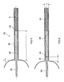
- the electrode system 35 is shown in detail in the plug 36.
- a passage 9 is a pin, for example, as in FIG. 6 shown a two-piece pin, the first part near discharge 38 is a cermet of Mo and Al 2 O 3 , and the second part 39 consists of niobium or NbZr or MoV. The implementation may for example also be partially encased by a helix.
- the second part 26 of the electrode has approximately the same diameter as the pin and is welded thereto. This is followed by the discharge side of the first part 25, whose diameter is significantly smaller, both parts are made of one piece.
- the first part may be pin-shaped, or may have a solid part or a coil as the head.
- the diameter of the second part should preferably be at least 10%, at most 60% greater than the diameter of the first part.
- the minimum value applies in particular if the electrode is pin-shaped.
- the step 27 between the two parts should coincide approximately with the end of the capillary.
- the mismatch A should be less than 10% of the length L.
- a typical value for A is 1 mm.
- FIG. 6 a further embodiment of an electrode system in the capillary is shown. It is preferred that the diameter D2 of the second part 26 of the electrode is between 120 and 140% of the diameter D1 of the first part 25.
- the diameter D2 of the second part should preferably approach as close as possible to the inner diameter ID of the capillary. It should be at least 95%, preferably at least 98% thereof.
- the second part of the electrode approximately flush or slightly recessed or be prominent, so for example, be used in a depth A up to 1 mm, in the capillary.
- connection point 40 is located as deep as possible in the capillary for implementation. It should have a depth T of for example 3 to 6 mm, this value also depends on the Wattage of the lamp.
- the implementation is in particular made up of two parts, namely a cermet as an inner and a niobium pin as a further outer part. Both parts of the bushing preferably have approximately the same diameter as the second part of the electrode and should deviate a maximum of 10% thereof. Thus, the dead volume is minimized throughout.
- welding but also mechanical fitting into a groove, etc. come into question as the connection technology between the second part and the bushing. However, a weld is preferred because it provides the safest hold.
Landscapes
- Engineering & Computer Science (AREA)
- Manufacturing & Machinery (AREA)
- Discharge Lamp (AREA)
- Vessels And Coating Films For Discharge Lamps (AREA)
Description
- Die Erfindung geht aus von einer Hochdruckentladungslampe mit keramischem Entladungsgefäß gemäß dem Oberbegriff des Anspruchs 1. Es kann sich dabei um Hochdruck-Entladungslampen handeln, wie sie insbesondere für die Allgemeinbeleuchtung verwendet werden.
- Aus der
EP-B 639 853 - Es ist Aufgabe der vorliegenden Erfindung, eine Hochdruckentladungslampe gemäß dem Oberbegriff des Anspruchs 1 bereitzustellen, bei der die Gefahr einer Beschädigung der Elektrode minimiert ist. Außerdem ist eine Verlängerung der Lebensdauer erwünscht.
- Diese Aufgaben werden durch die kennzeichnenden Merkmale des Anspruchs 1 gelöst. Besonders vorteilhafte Ausgestaltungen finden sich in den abhängigen Ansprüchen.
- Die Erfindung beschreibt ein Elektrodensystem für HID-Wechselstrom-Lampen, bestehend aus einer W-Elektrode, die aus einem rotationssymmetrischen Körper besteht und in zwei Teile mit unterschiedlichem Durchmesser gegliedert ist, so wie einer daran angesetzten Durchführung, die in einer Kapillare angeordnet ist. Die Erfindung reduziert das Totvolumen in der Kapillare sehr zuverlässig und mit hoher Genauigkeit.
- Bevorzugt besteht zwischen der Elektrode und der Durchführung eine Schweißverbindung. Diese wird durch die Länge der Elektrode, die weit in die Kapillare hineinragt auf eine unkritische Temperatur gebracht. Dadurch wird die Gefahr eines Abbruchs bzw. Abknickens der Elektrode aufgrund von Temperatureinflüssen reduziert.
- Im einzelnen wird erfindungsgemäß eine Hochdruckentladungslampe mit keramischem Entladungsgefäß beschrieben, in dem zwei Elektroden und eine lichtgebende Füllung enthalten sind, wobei an den Enden des Entladungsgefäßes Kapillaren sitzen, in denen Durchführungen abgedichtet sind, die jeweils mit einer Elektrode aus Wolfram verbunden sind. Dabei ist die Elektrode stiftförmig und aus zwei Teilen mit unterschiedlichem Durchmesser integral zusammengesetzt, wobei der erste Teil mit einem gegebenen Durchmesser D1 die Elektrodenspitze bildet und der zweite Teil mit einem Durchmesser D2 in der Kapillare sitzt, wobei der Durchmesser D2 des zweiten Teils mindestens 108 % des Durchmessers des ersten Teils ausmacht, wobei die Gesamtlänge L der Elektrode so zwischen dem ersten Teil mit einer Teillänge L1 und dem zweiten Teil mit einer Teillänge L2 aufgeteilt ist, dass L2 etwa 30 bis 70 % der Gesamtlänge L ausmacht, und wobei der Beginn des maximalen Durchmessers D2 mit dem Beginn der Kapillare zusammenfällt oder maximal davon um 10 % der Länge L abweicht.
- Bevorzugt beträgt der Durchmesser D2 des zweiten Teils mindestens 95 % des Innendurchmessers ID der Kapillare, so dass das Totvolumen minimiert ist.
- Insbesondere ist der zweite Teil mit der Durchführung durch eine Schweißung verbunden. Weiter empfiehlt sich, dass der Durchmesser der Durchführung auf mindestens 10 % genau dem Durchmesser des zweiten Teils entspricht.
- Dabei kann der Übergang zwischen D1 und D2 sprunghaft mittels einer Stufe erfolgen, er kann jedoch auch abgeschrägt sein, so dass ein allmählicher Übergang entsteht.
- Da die Elektrode aus einem Stück gefertigt ist, sollte der Durchmesser D2 maximal 160 % von D1 ausmachen, da sonst zuviel Abfall entsteht.
- Eine optimales Wärmemanagement kann dadurch erzielt werden, dass auf dem ersten Teil in der Nähe der Spitze eine zusätzliche Verdickung angebracht ist. Diese kann eine integraler Kopf sein, oder auch eine Wendel, die auf den ersten Teil aufgeschoben ist. bevorzugt ist der integrale Kopf, da er leicht in einem Arbeitsgang hergestellt werden kann, was den Abfall vermindert. Bevorzugt ist der maximale Durchmesser des Kopfs also gleich wie der des zweiten Teils. Die Wärmekapazität kann über die Länge des Kopfs eingestellt werden. Alternativ kann der Durchmesser des Kopfs, D3, zwischen D1 und D2 liegen.
- Bevorzugt wird die Elektrode und das Elektrodensystem für Hochdruckentladungs-Lampen verwendet, deren Füllung Metallhalogenide enthält.
- Vorteilhaft läst sich jetzt das Verhältnis der Durchmesser des ersten und zweiten Teils der Elektrode sehr genau einstellen und insbesondere so einstellen, dass das zweite Teil dem Innendurchmesser der Kapillare eng angepasst ist. Insbesondere sollten die Werte zwischen 1,3 und 1,6 liegen. Ein typischer Wert ist ein Faktor 1,4.
- Am ersten Teil sitzt häufig ein Elektrodenkopf, der insbesondere auch durch eine Wendel, eine Hülse oder massive Verdickung, wie an sich bekannt, realisiert sein kann. Er kann aber auch ein Stift ohne Verdickung sein.
- An den Durchmesser des ersten, dem Plasma zugewandten Teils der Elektrode werden andere Anforderungen gestellt als an den größeren Durchmesser des hinteren zweiten, der Einschmelzung zugewandten Teil. Die Elektrode ist bevorzugt aus Wolfram oder ähnlich hochschmelzendem Material hergestellt, insbesondere einer hoch Wolfram enthaltenden Verbindung.
- Der vordere, dem Plasma zugewandte erste Teil der W-Elektrode soll gerade soviel Wärme abführen, dass die Temperatur der Elektrodenspitze einerseits nicht so hoch ist, dass unnötig hohe Abdampfung von Wolfram erfolgt, andererseits soll die Wärmeabfuhr nicht so groß sein, dass in der Katodenphase (AC-Betrieb) Sputtern auftritt. Diese Anforderungen legen ein Optimum des Durchmessers der W-Elektrodenspitze im vorderen Teil fest.
- Für den optimalen Durchmesser des hinteren Teils, nämlich des der Einschmelzung zugewandten Schaftteils der Elektrode gelten andere Kriterien. Der optimale Durchmesser wird hauptsächlich durch die Fügbarkeit des Schaftteils mit den Cermet-, Molybdän-, Nb(Zr)- u./o. weitere denkbare Kapillardurchführungsbauteile in Richtung Glasloteinschmelzung bestimmt. Diese Anforderungen legen ein Optimum des Durchmessers des zweiten Teils fest. Er ist bestimmt durch die Bedingung, dass das Verhältnis zwischen Kapillardurchführung und Elektrodenschaftteil bevorzugt zwischen 0,5 und 1,0 liegt, Grenzwerte eingeschlossen.
- Erfindungsgemäße Elektroden für Entladungslampen sind aus hochtemperaturbeständigem Metall gefertigt. Geeignet ist insbesondere Wolfram, Molybdän, Tantal, Rhenium oder Legierungen derselben, aber auch Carbide dieser Metalle, insbesondere Tantalcarbid (TaC).
- Die Elektroden werden aus Rohlingen mit entsprechenden Abmessungen durch Drehen, Schleifen, Bohren, Ätzen etc. hergestellt. Besonders bevorzugt ist ein Laserverfahren wie in
DE 42 06 002 beschrieben. Gegebenenfalls wird durch geeignete Fertigungsprozesse wie Walzen und Hämmern noch zusätzlich Verformungsarbeit eingebracht, um die Gefügestabilität der Elektrodenmaterialien zu erhöhen. Als Elektrodenmaterialien dienen jetzt hochtemperaturfeste Metalle, wie z.B. W, Ta, Mo, Re bzw. deren Legierungen, die teilweise zusätzlich dotiert sind, um die Gefügestabilität der Materialien zu erhöhen. Vorzugsweise erfolgt die Dotierung zur Gefügestabilisierung mit Elementen wie z.B. K, Al und Si und zusätzlich mit Oxiden, Karbiden, Boriden, Nitriden und/oder den reinen Metallen (bzw. deren Legierungen) von Seltenerdelementen, der Lanthanoide, der Actinoide, wie z.B. La, Ce, Pr, Nd, Eu, Th, aber auch Sc, Ti, Y, Zr, Hf. Sie dienen nicht nur zur Gefügestabilisierung, sondern auch zur Senkung der Elektronenaustrittsarbeit. - In einer besonders bevorzugten ersten Ausführungsform werden einstückige Elektroden, insbesondere aus Wolfram, hergestellt, wobei die komplexe Kontur ein hinteres Schaftteil als zweites Teil, das zylindrisch ist, sowie ein Frontstück als erstes Teil besitzen kann, das einen Kopf aufweisen kann.
- Es lassen sich hochdichte Körper mit typisch 98 % (sogar bis zu mehr als 99 %) der theoretischen Dichte erzeugen.
- Damit wird insbesondere eine Optimierung des Wärmeflussverhaltens von Elektroden erreicht. Die Bearbeitung ist hier oft rein mechanisch durch spanende Werkzeuge. Bisher musste für derartige Elektroden ein Abfall von bis zu etwa 60 % in Kauf genommen werden. Hier kann jedoch günstig eine Lasersublimationsverfahren angewendet werden, das auf den Vorgaben der
DE-A 42 06 002 basiert. Insbesondere kann die Schaftlänge der W-Elektrode jetzt völlig variabel ausgelegt werden. Bekannt ist bisher das Problem, dass die Verbindungsstelle zwischen den früher verwendeten zwei Teilen, die in der Regel eine Schweißung ist, bei zu großer Nähe zur Entladung im Lampenbetrieb thermisch überlastet wird. Dies ist dann der Fall, wenn die Verbindung von W-Elektrode zur Durchführung zu nahe an das Ende der Kapillare in Richtung Entladungsvolumen gelegt wird. Bevorzugt ist bisher darauf zu achten, dass die Temperatur an der Verbindungsstelle nicht über 1500 K liegt, besonders bevorzugt nicht über 1300 K. Die Folge ist dann ein Abknicken der W-Elektrode an der Verbindungsstelle, die in aller Regel eine Schweißung ist. Berührt die W-Elektrode die Innenwand der Kapillare treten Risse in der Kapillare auf, durch die die Füllung aus dem Entladungsgefäß entweicht. Dies verkürzt die Lebensdauer, und die Lampe verlöscht. - Die unterschiedlichen Anforderungen an die beiden Teile der W-Elektrode werden jetzt am besten dadurch erfüllt, dass die Elektrode integral ist und dass das Wolframmaterial im vorderen ersten Teil der W-Elektrode abgetragen wird. Dies geschieht am besten durch mechanische, chemische oder thermo-mechanische Methoden wie Laserabtragung.
- Die vorliegenden Anmeldung bezieht sich auch auf eine Hochdruckentladungslampe mit einer derartigen Elektrode, insbesondere mit Metallhalogenidfüllung, wie sie vom Typus her schon aus der
EP-A 1 056 115 bekannt ist. - Verlängert man die Elektrode in die Kapillare hinein ohne den Durchmesser des zweiten Teils zu vergrößern, entsteht ein sehr großes Totvolumen mit den bekannten negativen Folgen. Dieses Totvolumen führt gewöhnlich zu größeren Farbtemperaturstreuungen, die wiederum nur durch eine Füllmengenanhebung kompensiert werden kann. Eine Füllmengenanhebung hat wiederum einen Anstieg der Wiederzündspitzenspannung zur Folge. Dadurch nimmt die Gefahr eines frühzeitigen Verlöschens der Lampe zu.
- Der Durchmesser des zweiten Teils soll daher dem Innendurchmesser der Kapillare möglichst gut angepasst sein und so das Totvolumen ausfüllen. Das Ende der Elektrode kann möglichst weit nach hinten in die Kapillare verlegt werden, bis zu 70 % der Gesamtlänge L der Elektrode.
- Im folgenden soll die Erfindung anhand mehrerer Ausführungsbeispiele näher erläutert werden. Es zeigen:
- Figur 1
- eine Metallhalogenidlampe mit keramischem Entladungsgefäß;
- Figur 2
- eine Elektrode gemäß der Erfindung im Detail;
- Figur 3 - 4
- je ein weiteres Ausführungsbeispiel einer Elektrode im Detail;
- Figur 5
- den Endbereich der Lampe der
Figur 1 mit Elektrodensystem im Detail; - Figur 6
- ein weiteres Ausführungsbeispiel eines Elektrodensystems.
- In
Figur 1 ist schematisch eine Metallhalogenidlampe mit einer Leistung von 150 W dargestellt. Sie besteht aus einem eine Lampenachse definierenden zylindrischen Außenkolben 1 aus Quarzglas, der zweiseitig gequetscht (2) und gesockelt (3) ist. Selbstverständlich kann die Lampe auch einseitig verschlossen und beispielsweise mit einem Schraubsockel versehen sein. Das axial angeordnete Entladungsgefäß 4 aus Al2O3-Keramik ist zylindrisch oder bauchig geformt und besitzt zwei Enden 6. Es ist mittels zweier Stromzuführungen 7, die mit den Sockelteilen 3 über Folien 8 verbunden sind, im Außenkolben 1 gehaltert. Die Stromzuführungen 7 sind mit Durchführungen 9 verschweißt, die jeweils in einem Endstopfen am Ende 6 des Entladungsgefäßes eingepasst sind. Der Endstopfen ist als ein langgezogenes Kapillarrohr 12 (Stopfenkapillare) ausgeführt. Das Ende 6 des Entladungsgefäßes und die Stopfenkapillare 12 sind beispielsweise miteinander direkt versintert. An der Durchführung sitzt entladungsseitig eine Elektrode 15. - Die Durchführung 9 ist jeweils als mehrteiliger Stift ausgeführt und ragt bis etwa drei Viertel der Länge des Kapillarrohrs 12 in dieses hinein. Daran erstreckt sich innerhalb des Kapillarrohrs 12 zum Entladungsvolumen hin ein zweiteiliger Elektrodenschaft 16 aus Wolfram mit einer am entladungsseitigen Ende aufgeschobenen Wendel 17.
- Die Füllung des Entladungsgefäßes besteht neben einem inerten Zündgas, z.B. Argon, aus Quecksilber und Zusätzen an Metallhalogeniden. Möglich ist beispielsweise auch die Verwendung einer Metallhalogenid-Füllung ohne Quecksilber, wobei als Zündgas beispielsweise Xenon und insbesondere ein hoher Druck, deutlich über 1,3 bar, gewählt werden kann.
- Der Stift 9 ist in die Stopfenkapillare 12 eingesetzt und mittels Glaslot 19 abgedichtet.
- In
Figur 2 ist eine Elektrode 15 im Detail gezeigt. Wichtig ist, dass die Elektrode ein integrales Bauteil ist. Der Durchmesser des vorderen Teils 25 ist D1 und der Durchmesser des hinteren Teils 26 ist D2. Die Gesamtlänge der Elektrode ist L. Die Länge des ersten Teils 25 ist L1 und die Länge des zweiten Teils 26 ist L2. Der Übergang zwischen beiden Teilen ist eine Stufe 27. - In
Figur 3 ist eine Elektrode 15 gezeigt, bei der der erste Teil 25 einen Kopf 28 besitzt, der ebenfalls integral hergestellt ist. Sein Durchmesser ist D3, seine Länge ist L3, dabei ist D1 < D3 ≤ D2. - In
Figur 4 ist eine Elektrode 30 gezeigt, bei der der Kopf eine separate Wendel 31 ist. Weiter ist gezeigt, dass zwischen erstem Teil 25 und zweitem Teil 26 eine Schräge 33 als Übergang verwendet wird. - In
Fig. 5 ist das Elektrodensystem 35 im Detail im Stopfen 36 gezeigt. Als Durchführung 9 dient ein Stift, beispielsweise auch wie inFigur 6 gezeigt ein zweiteiliger Stift, dessen erster entladungsnaher Teil 38 ein Cermet aus Mo und Al2O3 ist, und dessen zweiter Teil 39 aus Niob oder auch NbZr oder auch MoV besteht. Die Durchführung kann beispielsweise auch teilweise von einer Wendel ummantelt sein. Der zweite Teil 26 der Elektrode hat etwa den gleichen Durchmesser wie der Stift und ist mit diesem verschweißt. Daran schließt sich entladungsseitig der erste Teil 25 an, dessen Durchmesser deutlich kleiner ist, wobei beide Teile aus einem Stück gefertigt sind. Der erste Teil kann stiftförmig sein, oder als Kopf ein massives Teil oder eine Wendel besitzen. Dabei soll der Durchmesser des zweiten Teils bevorzugt mindestens 10 %, maximal 60 % größer sein als der Durchmesser des ersten Teils. Der Mindestwert gilt insbesondere, wenn die Elektrode stiftförmig ist. Die Stufe 27 zwischen beiden Teilen soll in etwa mit dem Ende der Kapillare zusammenfallen. Der Mismatch A soll weniger als 10 % der Länge L betragen. Ein typischer Wert für A ist 1 mm. - In
Figur 6 ist ein weiteres Ausführungsbeispiel eines Elektrodensystems in der Kapillare gezeigt. Bevorzugt ist, dass der Durchmesser D2 des zweiten Teils 26 der Elektrode zwischen 120 und 140 % des Durchmessers D1 des ersten Teils 25 beträgt. Der Durchmesser D2 des zweiten Teils sollte bevorzugt möglichst nahe an den Innendurchmesser ID der Kapillare herankommen. Er sollte mindestens 95 % davon, bevorzugt mindestens 98 % davon betragen. - Wichtig ist auch die relative Zuordnung in axialer Richtung. Dabei sollte bevorzugt, bezogen auf den Beginn der Kapillare, der zweite Teil der Elektrode annähernd bündig oder leicht vertieft oder vorstehend sein, also beispielsweise in einer Tiefe A bis zu 1 mm, in die Kapillare eingesetzt sein.
- Vorteilhaft ist außerdem, dass die Verbindungsstelle 40 zur Durchführung möglichst tief in der Kapillare sitzt. Sie sollte ein Tiefe T von beispielsweise 3 bis 6 mm haben, dieser Wert hängt auch von der Wattage der Lampe ab.
- Die Durchführung ist insbesondere aus zwei Teilen aufgebaut, nämlich einem Cermet als innenliegendem und einem Niobstift als weiter außenliegenden Teil. Beide Teile der Durchführung haben bevorzugt in etwa den gleichen Durchmesser wie das zweite Teil der Elektrode und sollten maximal 10 % davon abweichen. Somit ist das Totvolumen durchgehend minimiert.
- Als Verbindungstechnik zwischen zweitem Teil und Durchführung kommt Schweißen, aber auch mechanisches Einpassen in eine Nut etc. in Frage. Bevorzugt ist jedoch eine Schweißung, da sie den sichersten Halt gewährt.
Claims (9)
- Hochdruckentladungslampe mit keramischem Entladungsgefäß, in dem zwei Elektroden und eine lichtgebende Füllung enthalten sind, wobei an den Enden des Entladungsgefäßes Kapillaren sitzen, in denen Durchführungen abgedichtet sind, die jeweils mit einer Elektrode aus Wolfram, Rhenium oder einer Mischung oder Legierung beider Elemente, gegebenenfalls mit einem Zusatz von üblichen Dotierungen, verbunden sind, dadurch gekennzeichnet, dass die Elektrode stiftförmig ist und aus zwei Teilen mit unterschiedlichem Durchmesser integral zusammengesetzt ist, wobei der erste Teil mit einem gegebenen Durchmesser D1 die Elektrodenspitze bildet und der zweite Teil mit einem Durchmesser D2 in der Kapillare sitzt, wobei der Durchmesser D2 des zweiten Teils mindestens 108 % des Durchmessers D1 des ersten Teils ausmacht, wobei die Gesamtlänge L der Elektrode so zwischen dem ersten Teil mit einer Teillänge L1 und dem zweiten Teil mit einer Teillänge L2 aufgeteilt ist, dass L2 etwa 30 bis 70 % der Gesamtlänge L ausmacht, und wobei der Beginn des maximalen Durchmessers D2 mit dem Beginn der Kapillare zusammenfällt oder maximal davon um 10 % der Länge L abweicht.
- Hochdruckentladungslampe nach Anspruch 1, dadurch gekennzeichnet, dass der Durchmesser D2 des zweiten Teils mindestens 95 % des Innendurchmessers ID der Kapillare beträgt.
- Hochdruckentladungslampe nach Anspruch 1, dadurch gekennzeichnet, dass der zweite Teil mit der Durchführung durch eine Schweißung verbunden ist.
- Hochdruckentladungslampe nach Anspruch 1, dadurch gekennzeichnet, dass der Durchmesser der Durchführung auf mindestens 10 % genau dem Durchmesser des zweiten Teils entspricht.
- Hochdruckentladungslampe nach Anspruch 1, dadurch gekennzeichnet, dass der Übergang zwischen D1 und D2 sprunghaft mittels einer Stufe erfolgt.
- Hochdruckentladungslampe nach Anspruch 1, dadurch gekennzeichnet, dass der Durchmesser D2 maximal 160 % von D1 ausmacht.
- Hochdruckentladungslampe nach Anspruch 1, dadurch gekennzeichnet, dass auf dem ersten Teil in der Nähe der Spitze eine zusätzliche Verdickung angebracht ist.
- Hochdruckentladungslampe nach Anspruch 1, dadurch gekennzeichnet, dass die Füllung Metallhalogenide enthält.
- Hochdruckentladungslampe nach Anspruch 1, dadurch gekennzeichnet, dass, das Elektrodenmaterial mit mindestens einem der Elemente K, Al, Si, Y dotiert ist.
Applications Claiming Priority (2)
| Application Number | Priority Date | Filing Date | Title |
|---|---|---|---|
| DE202006002833U DE202006002833U1 (de) | 2006-02-22 | 2006-02-22 | Hochdruckentladungslampe mit keramischem Entladungsgefäß |
| PCT/EP2007/051414 WO2007096277A1 (de) | 2006-02-22 | 2007-02-14 | Hochdruckentladungslampe mit keramischem entladungsgefäss |
Publications (2)
| Publication Number | Publication Date |
|---|---|
| EP1987531A1 EP1987531A1 (de) | 2008-11-05 |
| EP1987531B1 true EP1987531B1 (de) | 2009-12-02 |
Family
ID=36442249
Family Applications (1)
| Application Number | Title | Priority Date | Filing Date |
|---|---|---|---|
| EP07726370A Not-in-force EP1987531B1 (de) | 2006-02-22 | 2007-02-14 | Hochdruckentladungslampe mit keramischem entladungsgefäss |
Country Status (7)
| Country | Link |
|---|---|
| US (1) | US8018156B2 (de) |
| EP (1) | EP1987531B1 (de) |
| JP (1) | JP3153262U (de) |
| CN (1) | CN101385117A (de) |
| CA (1) | CA2642578A1 (de) |
| DE (2) | DE202006002833U1 (de) |
| WO (1) | WO2007096277A1 (de) |
Families Citing this family (6)
| Publication number | Priority date | Publication date | Assignee | Title |
|---|---|---|---|---|
| DE202007013119U1 (de) * | 2007-09-19 | 2008-10-23 | Osram Gesellschaft mit beschränkter Haftung | Hochdruckentladungslampe |
| EP2387792A1 (de) * | 2009-01-14 | 2011-11-23 | Koninklijke Philips Electronics N.V. | Metallhalidlampe mit keramikgasentladung und hoher farbtemperatur |
| DE102009055123A1 (de) * | 2009-12-22 | 2011-06-30 | Osram Gesellschaft mit beschränkter Haftung, 81543 | Keramische Elektrode für eine Hochdruckentladungslampe |
| JP5666001B2 (ja) * | 2010-10-19 | 2015-02-04 | オスラム ゲーエムベーハーOSRAM GmbH | 高圧放電ランプのためのセラミック製の導入線 |
| US9093256B2 (en) * | 2011-09-30 | 2015-07-28 | Koninklijke Philips N.V. | Discharge lamp |
| DE102012215184A1 (de) * | 2012-08-27 | 2014-02-27 | Osram Gmbh | Hochdruckentladungslampe |
Family Cites Families (37)
| Publication number | Priority date | Publication date | Assignee | Title |
|---|---|---|---|---|
| JPH0582086A (ja) | 1991-09-20 | 1993-04-02 | Toshiba Lighting & Technol Corp | メタルハライドランプ |
| DE4206002A1 (de) | 1992-02-27 | 1993-09-02 | Philips Patentverwaltung | Verfahren zum erzeugen eines musters in der oberflaeche eines werkstuecks |
| DE9206727U1 (de) * | 1992-05-18 | 1992-07-16 | Patent-Treuhand-Gesellschaft für elektrische Glühlampen mbH, 8000 München | Hochdruckentladungslampe |
| DE9207816U1 (de) * | 1992-06-10 | 1992-08-20 | Patent-Treuhand-Gesellschaft für elektrische Glühlampen mbH, 8000 München | Hochdruckentladungslampe |
| US5424609A (en) * | 1992-09-08 | 1995-06-13 | U.S. Philips Corporation | High-pressure discharge lamp |
| DE4327535A1 (de) | 1993-08-16 | 1995-02-23 | Patent Treuhand Ges Fuer Elektrische Gluehlampen Mbh | Hochdruckentladungslampe mit keramischem Entladungsgefäß |
| EP0829096B1 (de) * | 1996-02-28 | 2005-04-20 | Koninklijke Philips Electronics N.V. | Metallhalogenidlampe |
| US5661367A (en) * | 1996-08-08 | 1997-08-26 | Philips Electronics North America Corporation | High pressure series arc discharge lamp construction with simplified starting aid |
| JP3264189B2 (ja) * | 1996-10-03 | 2002-03-11 | 松下電器産業株式会社 | 高圧金属蒸気放電ランプ |
| TW343348B (en) * | 1996-12-04 | 1998-10-21 | Philips Electronics Nv | Metal halide lamp |
| CN1149628C (zh) * | 1997-04-25 | 2004-05-12 | 皇家菲利浦电子有限公司 | 高压气体放电灯 |
| JP4316699B2 (ja) * | 1997-07-25 | 2009-08-19 | ハリソン東芝ライティング株式会社 | 高圧放電ランプおよび照明装置 |
| JPH11135073A (ja) | 1997-10-28 | 1999-05-21 | Matsushita Electric Works Ltd | 金属蒸気放電灯 |
| DE19749908A1 (de) | 1997-11-11 | 1999-05-12 | Patent Treuhand Ges Fuer Elektrische Gluehlampen Mbh | Elektrodenbauteil für Entladungslampen |
| US6147453A (en) * | 1997-12-02 | 2000-11-14 | U.S. Philips Corporation | Metal-halide lamp with lithium and cerium iodide |
| JP3318250B2 (ja) * | 1997-12-26 | 2002-08-26 | 松下電器産業株式会社 | 金属蒸気放電ランプ |
| US6414436B1 (en) * | 1999-02-01 | 2002-07-02 | Gem Lighting Llc | Sapphire high intensity discharge projector lamp |
| DE60019698T2 (de) * | 1999-04-29 | 2006-04-06 | Koninklijke Philips Electronics N.V. | Metallhalogenidlampe |
| JP3177230B2 (ja) * | 1999-05-25 | 2001-06-18 | 松下電子工業株式会社 | 金属蒸気放電ランプ |
| US6307321B1 (en) * | 1999-07-14 | 2001-10-23 | Toshiba Lighting & Technology Corporation | High-pressure discharge lamp and lighting apparatus |
| JP4884637B2 (ja) * | 2000-04-19 | 2012-02-29 | コーニンクレッカ フィリップス エレクトロニクス エヌ ヴィ | 高圧放電ランプ |
| DE10026802A1 (de) * | 2000-05-31 | 2002-01-03 | Patent Treuhand Ges Fuer Elektrische Gluehlampen Mbh | Metallhalogenidlampe mit keramischem Entladungsgefäß |
| US6812642B1 (en) * | 2000-07-03 | 2004-11-02 | Ngk Insulators, Ltd. | Joined body and a high-pressure discharge lamp |
| US20020117965A1 (en) * | 2001-02-23 | 2002-08-29 | Osram Sylvania Inc. | High buffer gas pressure ceramic arc tube and method and apparatus for making same |
| US6791267B2 (en) * | 2001-10-02 | 2004-09-14 | Ngk Insulators, Ltd. | High pressure discharge lamps, lighting systems, head lamps for automobiles and light emitting vessels for high pressure discharge lamps |
| JP2003297289A (ja) * | 2002-01-30 | 2003-10-17 | Toshiba Lighting & Technology Corp | 高圧放電ランプおよび多重管形高圧放電ランプならびに照明装置 |
| EP1372184A3 (de) * | 2002-06-14 | 2006-05-31 | Patent-Treuhand-Gesellschaft für elektrische Glühlampen mbH | Elektrodensystem für eine Metallhalogenidlampe und zugehörige Lampe |
| US6984938B2 (en) * | 2002-08-30 | 2006-01-10 | Matsushita Electric Industrial Co., Ltd | Metal vapor discharge lamp and lighting apparatus capable of stable maintenance of characteristics |
| US7525252B2 (en) * | 2002-12-27 | 2009-04-28 | General Electric Company | Sealing tube material for high pressure short-arc discharge lamps |
| JP4229437B2 (ja) * | 2003-06-05 | 2009-02-25 | 株式会社小糸製作所 | 自動車用放電バルブおよび自動車前照灯 |
| EP1656692A2 (de) | 2003-08-15 | 2006-05-17 | Koninklijke Philips Electronics N.V. | Entladungslampe mit elektroden mit konischem rutschteil |
| EP1730766B1 (de) * | 2004-02-23 | 2013-03-27 | OSRAM GmbH | Elektrodensystem für eine hochdruckentladungslampe |
| DE202004013922U1 (de) * | 2004-09-07 | 2004-11-18 | Patent-Treuhand-Gesellschaft für elektrische Glühlampen mbH | Metallhalogenidlampe mit keramischem Entladungsgefäß |
| US20080001543A1 (en) * | 2004-10-29 | 2008-01-03 | Takahito Kashiwagi | Metal Halide Lamp and Lighting Equipment |
| CN101288147B (zh) * | 2005-01-19 | 2010-12-29 | 皇家飞利浦电子股份有限公司 | 高压放电灯 |
| CA2540410A1 (en) * | 2005-03-24 | 2006-09-24 | Patent-Treuhand-Gesellschaft Fuer Elektrische Gluehlampen Mbh | Metal halide lamp with ceramic discharge vessel |
| US7795814B2 (en) * | 2008-06-16 | 2010-09-14 | Resat Corporation | Interconnection feedthroughs for ceramic metal halide lamps |
-
2006
- 2006-02-22 DE DE202006002833U patent/DE202006002833U1/de not_active Expired - Lifetime
-
2007
- 2007-02-14 CN CNA2007800060640A patent/CN101385117A/zh active Pending
- 2007-02-14 CA CA002642578A patent/CA2642578A1/en not_active Abandoned
- 2007-02-14 EP EP07726370A patent/EP1987531B1/de not_active Not-in-force
- 2007-02-14 WO PCT/EP2007/051414 patent/WO2007096277A1/de not_active Ceased
- 2007-02-14 DE DE502007002179T patent/DE502007002179D1/de active Active
- 2007-02-14 US US12/224,226 patent/US8018156B2/en not_active Expired - Fee Related
- 2007-02-14 JP JP2009600002U patent/JP3153262U/ja not_active Expired - Fee Related
Also Published As
| Publication number | Publication date |
|---|---|
| DE202006002833U1 (de) | 2006-05-04 |
| US8018156B2 (en) | 2011-09-13 |
| JP3153262U (ja) | 2009-09-03 |
| US20090021172A1 (en) | 2009-01-22 |
| EP1987531A1 (de) | 2008-11-05 |
| DE502007002179D1 (de) | 2010-01-14 |
| CN101385117A (zh) | 2009-03-11 |
| CA2642578A1 (en) | 2007-08-30 |
| WO2007096277A1 (de) | 2007-08-30 |
Similar Documents
| Publication | Publication Date | Title |
|---|---|---|
| EP0607149B1 (de) | Verfahren zum herstellen einer metallhalogenid-entladungslampe mit keramischem entladungsgefäss | |
| DE69207842T2 (de) | Hochdruckentladungslampe und Verfahren zur Herstellung | |
| EP0917179A2 (de) | Elektrodenbauteil für Entladungslampen | |
| EP1987531A1 (de) | Hochdruckentladungslampe mit keramischem entladungsgefäss | |
| EP0901150B1 (de) | Elektrode und Verfahren sowie Vorrichtung zur Herstellung derselben | |
| EP0528427A1 (de) | Hochdruckentladungslampe | |
| DE9415217U1 (de) | Hochdruckentladungslampe | |
| EP0451647A2 (de) | Hochdruckentladungslampe und Verfahren zu ihrer Herstellung | |
| EP0887840A2 (de) | Metallhalodenidlampe mit keramischem Entladungsgefäss | |
| WO2003020462A1 (de) | Stabförmiges werkzeug zur spanenden bearbeitung eines werkstücks | |
| EP3948934B1 (de) | Elektrode für eine gasentladungslampe und gasentladungslampe | |
| EP0639853B1 (de) | Hochdruckentladungslampe mit keramischem Entladungsgefäss | |
| DE19908688A1 (de) | Metallhalogenidlampe mit keramischem Entladungsgefäß | |
| EP1048052B1 (de) | Verfahren zur herstellung einer elektrode für entladungslampen | |
| EP1372184A2 (de) | Elektrodensystem für eine Metallhalogenidlampe und zugehörige Lampe | |
| EP1351278B1 (de) | Metallhalogenidlampe mit keramischem Entladungsgefäss | |
| DE102006024238A1 (de) | Hochdruckentladungslampe | |
| EP1434252A2 (de) | Metallhalogenidlampe mit keramischem Entladungsgefäss, Elektrodensystem für eine solche Lampe und Herstellungsverfahren eines solchen Systems | |
| EP4545196B1 (de) | Vorrichtung zur herstellung kleinvolumiger tubenverpackungsrohlinge | |
| EP1439567B1 (de) | Elektrode für eine Hochdruckentladungslampe | |
| DE202006004567U1 (de) | Elektrode für Hochdruckentladungslampen und zugehörige Lampe | |
| DE102011075899A1 (de) | Gasentladungslampe und Elektrode für eine Gasentladungslampe | |
| DE102006011732A1 (de) | Metallhalogenidlampe mit keramischen Entladungsgefäß | |
| WO2017177244A1 (de) | Anode für eine hochdruck-entladungslampe | |
| WO2005062343A2 (de) | Elektrode für eine hochdruckentladungslampe |
Legal Events
| Date | Code | Title | Description |
|---|---|---|---|
| PUAI | Public reference made under article 153(3) epc to a published international application that has entered the european phase |
Free format text: ORIGINAL CODE: 0009012 |
|
| 17P | Request for examination filed |
Effective date: 20080718 |
|
| AK | Designated contracting states |
Kind code of ref document: A1 Designated state(s): BE DE FR HU NL |
|
| RAP1 | Party data changed (applicant data changed or rights of an application transferred) |
Owner name: OSRAM GESELLSCHAFT MIT BESCHRAENKTER HAFTUNG |
|
| RBV | Designated contracting states (corrected) |
Designated state(s): BE DE FR HU NL |
|
| GRAP | Despatch of communication of intention to grant a patent |
Free format text: ORIGINAL CODE: EPIDOSNIGR1 |
|
| GRAS | Grant fee paid |
Free format text: ORIGINAL CODE: EPIDOSNIGR3 |
|
| GRAA | (expected) grant |
Free format text: ORIGINAL CODE: 0009210 |
|
| AK | Designated contracting states |
Kind code of ref document: B1 Designated state(s): BE DE FR HU NL |
|
| REF | Corresponds to: |
Ref document number: 502007002179 Country of ref document: DE Date of ref document: 20100114 Kind code of ref document: P |
|
| REG | Reference to a national code |
Ref country code: NL Ref legal event code: VDEP Effective date: 20091202 |
|
| REG | Reference to a national code |
Ref country code: HU Ref legal event code: AG4A Ref document number: E007175 Country of ref document: HU |
|
| PG25 | Lapsed in a contracting state [announced via postgrant information from national office to epo] |
Ref country code: NL Free format text: LAPSE BECAUSE OF FAILURE TO SUBMIT A TRANSLATION OF THE DESCRIPTION OR TO PAY THE FEE WITHIN THE PRESCRIBED TIME-LIMIT Effective date: 20091202 |
|
| PLBE | No opposition filed within time limit |
Free format text: ORIGINAL CODE: 0009261 |
|
| STAA | Information on the status of an ep patent application or granted ep patent |
Free format text: STATUS: NO OPPOSITION FILED WITHIN TIME LIMIT |
|
| 26N | No opposition filed |
Effective date: 20100903 |
|
| REG | Reference to a national code |
Ref country code: FR Ref legal event code: ST Effective date: 20101029 |
|
| PG25 | Lapsed in a contracting state [announced via postgrant information from national office to epo] |
Ref country code: FR Free format text: LAPSE BECAUSE OF NON-PAYMENT OF DUE FEES Effective date: 20100301 |
|
| PGFP | Annual fee paid to national office [announced via postgrant information from national office to epo] |
Ref country code: BE Payment date: 20110316 Year of fee payment: 5 Ref country code: DE Payment date: 20110418 Year of fee payment: 5 |
|
| PGFP | Annual fee paid to national office [announced via postgrant information from national office to epo] |
Ref country code: HU Payment date: 20110418 Year of fee payment: 5 |
|
| REG | Reference to a national code |
Ref country code: DE Ref legal event code: R081 Ref document number: 502007002179 Country of ref document: DE Owner name: OSRAM AG, DE Free format text: FORMER OWNER: OSRAM GESELLSCHAFT MIT BESCHRAENKTER HAFTUNG, 81543 MUENCHEN, DE Effective date: 20111214 |
|
| BERE | Be: lapsed |
Owner name: OSRAM G.M.B.H. Effective date: 20120228 |
|
| PG25 | Lapsed in a contracting state [announced via postgrant information from national office to epo] |
Ref country code: HU Free format text: LAPSE BECAUSE OF NON-PAYMENT OF DUE FEES Effective date: 20120215 |
|
| REG | Reference to a national code |
Ref country code: DE Ref legal event code: R119 Ref document number: 502007002179 Country of ref document: DE Effective date: 20120901 |
|
| PG25 | Lapsed in a contracting state [announced via postgrant information from national office to epo] |
Ref country code: BE Free format text: LAPSE BECAUSE OF NON-PAYMENT OF DUE FEES Effective date: 20120228 |
|
| PG25 | Lapsed in a contracting state [announced via postgrant information from national office to epo] |
Ref country code: DE Free format text: LAPSE BECAUSE OF NON-PAYMENT OF DUE FEES Effective date: 20120901 |