EP1056115A2 - High pressure discharge lamp - Google Patents
High pressure discharge lamp Download PDFInfo
- Publication number
- EP1056115A2 EP1056115A2 EP00110701A EP00110701A EP1056115A2 EP 1056115 A2 EP1056115 A2 EP 1056115A2 EP 00110701 A EP00110701 A EP 00110701A EP 00110701 A EP00110701 A EP 00110701A EP 1056115 A2 EP1056115 A2 EP 1056115A2
- Authority
- EP
- European Patent Office
- Prior art keywords
- metal pipe
- electrode
- lamp
- electrode pin
- high pressure
- Prior art date
- Legal status (The legal status is an assumption and is not a legal conclusion. Google has not performed a legal analysis and makes no representation as to the accuracy of the status listed.)
- Granted
Links
Images




Classifications
-
- H—ELECTRICITY
- H01—ELECTRIC ELEMENTS
- H01J—ELECTRIC DISCHARGE TUBES OR DISCHARGE LAMPS
- H01J61/00—Gas-discharge or vapour-discharge lamps
- H01J61/82—Lamps with high-pressure unconstricted discharge having a cold pressure > 400 Torr
- H01J61/822—High-pressure mercury lamps
-
- H—ELECTRICITY
- H01—ELECTRIC ELEMENTS
- H01J—ELECTRIC DISCHARGE TUBES OR DISCHARGE LAMPS
- H01J61/00—Gas-discharge or vapour-discharge lamps
- H01J61/02—Details
- H01J61/04—Electrodes; Screens; Shields
- H01J61/06—Main electrodes
- H01J61/073—Main electrodes for high-pressure discharge lamps
- H01J61/0732—Main electrodes for high-pressure discharge lamps characterised by the construction of the electrode
Definitions
- the present invention relates to a high pressure discharge lamp. It relates in particular to a high pressure discharge lamp that is characterized by electrodes inside a discharge tube.
- a conventional electrode inside a discharge tube of a high pressure discharge lamp includes an electrode pin made of tungsten and an electrode coil made of tungsten that surrounds the electrode pin.
- the known electrode coil is formed by which a wire having a smaller wire diameter than that of the electrode pin is coiled to make one or two layers around the electrode pin. Further known structures are that with a tip of the electrode pin located in the electrode coil and that with the tip of the electrode pin being in the same plane as or protruding beyond an end of the electrode coil in the central side of the discharge tube.
- the purpose of providing the electrode coil to the electrode pin is to lower the temperature of the tip of the electrode pin during the discharge so as to achieve an optimal temperature, thereby reducing the evaporation of tungsten on the tip of the electrode pin and suppressing the blackening of the discharge tube. It is another important purpose to form the electrode coil with a thin wire, thereby increasing the electrolytic strength and improving the startup performance of the lamp.
- the electrode pin and the electrode coil are fixed to each other by welding or a mechanical insertion (that is, a method for obtaining the fitting strength by making the inner diameter of the electrode coil slightly smaller than the outer diameter of the electrode pin and mechanically pushing the electrode pin into the electrode coil).
- a mechanical insertion that is, a method for obtaining the fitting strength by making the inner diameter of the electrode coil slightly smaller than the outer diameter of the electrode pin and mechanically pushing the electrode pin into the electrode coil.
- the electrode coil is formed with a wire, the contact area of the electrode pin and the electrode coil is very small, and thus is less effective in lowering the tip temperature of the electrode pin.
- the tip temperature of the electrode pin varies correspondingly. This generates a variation of the evaporation degree of tungsten on the tip of the electrode.
- the evaporated tungsten adheres to the inner surface of a discharge tube so that the discharge tube blackens, thus considerably reducing a light flux of the lamp.
- higher temperature of the discharge tube and higher lamp voltage are caused so as to accelerate the dying out of the lamp.
- the electrode coil is formed by dense coiling and gaps occur between coil pitches, then the thermal conduction is greatly lowered, making the above problems still more serious.
- the present invention has the following configuration.
- a high pressure discharge lamp includes a discharge tube, a pair of electrodes comprising an electrode pin and a metal pipe surrounding the electrode pin arranged inside the discharge tube, and mercury sealed in the discharge tube.
- Fig. 1 shows a 70 W metal halide lamp in accordance with a first embodiment of the present invention.
- a discharge tube 1 made of ceramics is rigidly supported by metal wires 3a and 3b inside an outer tube 2.
- One end of the outer tube 2 is provided with a stem 3, which seals the outer tube 2 air-tightly.
- a predetermined amount of mercury, argon as a noble gas for a starting gas, and iodides of dysprosium (Dy), thulium (Tm), holmium (Ho), thallium (Tl) and sodium (Na) as metal halides are sealed in the discharge tube 1.
- Numeral 4 denotes a lamp base.
- Fig. 2 is a cross-sectional view illustrating a schematic configuration of the discharge tube in accordance with the present embodiment.
- the discharge tube 1 made of ceramics includes a main cylindrical portion 5 with an outer diameter of 7.8 mm and a wall thickness of 0.6 mm and tubular cylindrical portions 6 with an outer diameter of 2.6 mm and an inner diameter of 0.8 mm provided at both end portions of the main cylindrical portion 5.
- the main cylindrical portion 5 and the tubular cylindrical portions 6 are sintered into one piece with ring portions 7 with a wall thickness of 1.7 mm.
- Lead-in wires 9 having an electrode 8 at the tip portion thereof are inserted into both of the tubular cylindrical portions 6 such that the tip of electrode 8 is located inside the main cylindrical portion 5.
- the lead-in wire 9 is sealed in the tubular cylindrical portion 6 with a sealing material 10, and a sealing portion 11 is formed in the tubular cylindrical portion 6.
- the electrode 8 includes an electrode pin 12 made of tungsten with an outer diameter ⁇ of 0.4 mm and a metal pipe 13 made of tungsten with a wall thickness of 0.2 mm and an entire length of 1.5 mm that surrounds the electrode pin 12.
- the metal pipe 13 is welded and fixed to the electrode pin 12.
- the electrode pin 12 protrudes beyond the end of the metal pipe 13 towards the center of the discharge tube, and the protrusion length L is 1.0 mm.
- numeral 14 denotes a mercury pellet
- numeral 15 denotes an iodide pellet in Fig. 2.
- the lamp of one example of the present invention formed according to the configuration described above is called a lamp A.
- a lamp of a conventional configuration using an electrode coil as shown in Fig. 3(B) was evaluated at the same time.
- the electrode shown in Fig. 3(B) is configured such that an electrode coil 16 made of a tungsten wire with a wire diameter of 0.1 mm is coiled to obtain two layers around the same electrode pin 12 as that of the lamp A (for simplification, only one layer is shown in the figure).
- the entire length of the portion of the electrode coil 16 is 1.5 mm, which is the same as the lamp A of one example of the present invention.
- the lamp using this electrode coil 16 is called a lamp B.
- Fig. 4 shows the result of the lifetime evaluation.
- the luminous flux maintenance factor (%) in the vertical axis equals ((light flux value of a certain period of time after turning on the lamp)/(total light flux value of 100 hours after turning on the lamp) ⁇ 100) .
- Fig. 4 shows a mean value of the twenty evaluated lamps.
- the luminous flux maintenance factor of the lamp A is expressed by LA, and that of the lamp B is expressed by LB.
- the luminous flux maintenance factor of the lamp B which is a conventional product
- that of the lamp A which is one example of the present invention
- the lamp A had a smaller degree of the discharge tube blackening. In other words, it was confirmed that the present invention could achieve excellent lifetime characteristics.
- Table. 1 shows the luminous flux maintenance factors of the respective lamps after 6000 hours use.
- the configuration of the electrode 8 shown in Fig. 3(A) was used.
- the lifetimes when the outer diameter ⁇ was set to 0.4 mm were evaluated for five different protrusion lengths L, namely 0 mm, 1.0 mm, 2.0 mm, 3.0 mm and 3.5 mm, as a parameter.
- Fig. 4 also shows these results.
- the luminous flux maintenance factors of individual cases where the protrusion lengths L are 0 mm, 1.0 mm, 2.0 mm, 3.0 mm and 3.5 mm are expressed by La-0, La-1.0, La-2.0, La-3.0 and La-3.5.
- the luminous flux maintenance factor As is clearly shown in Fig. 4, as the protrusion length L becomes longer, the luminous flux maintenance factor after 6000 hours use declines.
- the protrusion length L is 3.5 mm, the luminous flux maintenance factor is the same as that of the lamp B of the conventional electrode configuration.
- the longer the protrusion length L becomes the smaller the effect of lowering the tip temperature of the electrode pin 12 becomes, leading to the evaporation of tungsten on the tip of the electrode pin and blackening of the discharge tube in a larger degree.
- the electrode having the configuration shown in Fig. 3(A) was used to evaluate the lifetime in a similar manner.
- the result confirmed that the lamps of all types achieved better lifetime characteristics and smaller variation of the lifetime characteristics between lamps than the lamp using the conventional electrode configuration shown in Fig. 3(B).
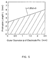
- the outer diameter ⁇ of the electrode pin 12 was changed according to wattages and the protrusion length L was used as a parameter so that the lifetimes were evaluated.
- a metal pipe 18 both of whose end portions are processed by polishing as shown in Fig. 3(D) was used to evaluate the lifetime.
- the luminous flux decline factor (%) was calculated with ((light flux value of a certain time) / (light flux value of the start of lamp operation) ⁇ 100) .
- the lamp using the metal pipe 18 whose end portions are processed by polishing showed better lifetime characteristics. Both lamps showed the same tendency of luminous flux deterioration at the 100 hours or longer operation time.
- the metal pipe 13 whose end portions are not processed by polishing has a burr on the cut surface in the end portions thereof, and the local temperature of the burr portion rises during the lamp operation, causing tungsten to evaporate in the discharge tube. Since the tungsten in the burr portion finishes evaporating by the time approximately 100 hours has passed after the start of the lamp operation, the metal pipes 13 and 18 show the same tendency of luminous flux deterioration at the 100 hours or longer operation time. In other words, it could be confirmed that polishing the end portions of the metal pipe to remove the burr provided a more preferable structure as a metal pipe in reducing an early light flux deterioration. Although it is not always necessary that the both ends of the metal pipe are processed by polishing, it is preferable that the both ends are polished because the effect described above becomes more apparent.
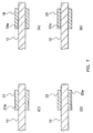
- Fig. 7 shows another configurational example of the metal pipe of the electrode in accordance with the present invention.
- Fig. 7(A) shows a metal pipe 19 that is provided with roughness on its internal circumferential surface by forming grooves 19a in the circumferantial direction.
- Fig. 7(B) shows a metal pipe 20 that is provided with roughness on its internal circumferential surface by forming grooves 20a in the longitudinal direction.
- Such metal pipes 19 and 20 that are made of tungsten and are provided with the roughness on their internal surfaces, as shown in Figs. 7(A) and (B), are advantageous in that welding to the electrode pin 12 can be performed easily.
- Fig. 7(C) shows a metal pipe 21 that is provided with roughness on its external circumferential surface by forming grooves 21a in the circumferantial direction.
- Fig. 7(D) shows a metal pipe 22 that is provided with roughness on its external circumferential surface by forming grooves 22a in the longitudinal direction.
- Such metal pipes 21 and 22 that are made of tungsten and are provided with the roughness on their external surfaces, as shown in Figs. 7(C) and (D), also are advantageous in that welding to the electrode pin 12 can be performed easily. This is because the contact portion of the electrode pin and the metal pipe becomes easier to melt during welding.
- the roughness in the circumferential direction as in Figs. 7(A) and (C) may be formed only on a part of the longitudinal direction of, as is shown in the figure, or across an entire length of the metal pipe.
- the roughness in the longitudinal direction as in Figs. 7(B) and (D) may be formed only on a part of the circumferential direction of, as is shown in the figure, or around an entire circumference of the metal pipe.
- the roughness may be provided to both internal and external circumferential surfaces.
- the roughness may be formed by providing a dotted convex or concave portion.
- an annular metal pipe as the metal pipe 13 using a partially cut-out metal pipe 23 that is provided with a slit 23a in the longitudinal direction as shown in Fig. 8 also can improve lifetime and the variation of lifetime characteristics between lamps.
- the shape of the cut-out portion is not limited to that of the slit formed across an entire length in the longitudinal direction, which is shown in Fig. 8.
- it can be changed optionally into a slit formed only in a part of the longitudinal direction, a slit formed spirally in a predetermined length, a notch formed in a part of an end portion, an opening penetrating a part of its external circumference, or the like.
- the metal pipe "surrounds" the electrode pin. This "surrounding" includes not only surrounding an entire circumference of the electrode pin as the metal pipe 13 does, but substantially surrounding the electrode pin with a metal pipe having a cut-out portion such as that in Fig. 8.
- tungsten was used as a material for the metal pipe 13.
- a metal pipe formed with tungsten containing approximately 2 wt% of thorium (Th) also can be improve the lifetime and the variation of lifetime characteristics between lamps, and even achieves a better startup performance.
- the embodiment of the present invention described a metal halide lamp using a transparent ceramic as the discharge tube 1.
- quartz instead of the transparent ceramic, quartz may be used.
- the material for the discharge tube as long as it has excellent thermal resistance and transmittance.
- the embodiment of the present invention described a lamp using, besides mercury and argon (Ar), iodides of dysprosium (Dy), thulium (Tm), holmium (Ho), sodium (Na) and thallium (Tl) as a material to be sealed in the discharge tube.
- argon (Ar) instead of argon (Ar), xenon (Xe) or neon (Ne) may be used.
- Xe xenon
- Ne neon
Landscapes
- Discharge Lamp (AREA)
- Discharge Lamps And Accessories Thereof (AREA)
- Vessels And Coating Films For Discharge Lamps (AREA)
Abstract
Description

Claims (8)
- A high pressure discharge lamp comprising:a discharge tube (1);a pair of electrodes (8) comprising an electrode pin (12) and a metal pipe (13,17-23) surrounding said electrode pin (12) arranged inside said discharge tube (1); andmercury sealed in said discharge tube (1).
- The high pressure discharge lamp according to claim 1, satisfying
- The high pressure discharge lamp according to claim 1 or 2, characterized in that at least one end of said metal pipe (17,18) is processed by polishing.
- The high pressure discharge lamp according to claim 1, 2 or 3 characterized in that said metal pipe (19,20) has roughness on at least a part of its internal surface.
- The high pressure discharge lamp according to claim 1, 2, 3 or 4 characterized in that said metal pipe (21,22) has roughness on at least a part of its external surface.
- The high pressure discharge lamp according to any of claims 1 to 5, characterized in that at least a part of said metal pipe (23) is cut out.
- The high pressure discharge lamp according to any of claims 1 to 6, characterized in that a main material for said metal pipe (13,17-23) is tungsten.
- The high pressure discharge lamp according to any of claims 1 to 7, characterized in that a material for said metal pipe (13,17-23) comprises thorium (Th).
Applications Claiming Priority (2)
| Application Number | Priority Date | Filing Date | Title |
|---|---|---|---|
| JP14339299 | 1999-05-24 | ||
| JP14339299A JP3238909B2 (en) | 1999-05-24 | 1999-05-24 | Metal halide lamp |
Publications (3)
| Publication Number | Publication Date |
|---|---|
| EP1056115A2 true EP1056115A2 (en) | 2000-11-29 |
| EP1056115A3 EP1056115A3 (en) | 2004-08-11 |
| EP1056115B1 EP1056115B1 (en) | 2007-03-07 |
Family
ID=15337708
Family Applications (1)
| Application Number | Title | Priority Date | Filing Date |
|---|---|---|---|
| EP00110701A Expired - Lifetime EP1056115B1 (en) | 1999-05-24 | 2000-05-19 | High pressure discharge lamp |
Country Status (5)
| Country | Link |
|---|---|
| US (1) | US6342764B1 (en) |
| EP (1) | EP1056115B1 (en) |
| JP (1) | JP3238909B2 (en) |
| CN (1) | CN1149625C (en) |
| DE (1) | DE60033728T2 (en) |
Cited By (4)
| Publication number | Priority date | Publication date | Assignee | Title |
|---|---|---|---|---|
| EP1056116A3 (en) * | 1999-05-25 | 2001-11-14 | Matsushita Electric Industrial Co., Ltd. | Electrode for a metal halide lamp |
| US6469442B2 (en) | 1999-05-25 | 2002-10-22 | Matsushita Electric Industrial Co., Ltd. | Metal vapor discharge lamp |
| US6646379B1 (en) | 1998-12-25 | 2003-11-11 | Matsushita Electric Industrial Co., Ltd. | Metal vapor discharge lamp having cermet lead-in with improved luminous efficiency and flux rise time |
| WO2006098956A1 (en) * | 2005-03-09 | 2006-09-21 | General Electric Company | Discharge tubes |
Families Citing this family (14)
| Publication number | Priority date | Publication date | Assignee | Title |
|---|---|---|---|---|
| JP3686286B2 (en) * | 1999-06-25 | 2005-08-24 | 株式会社小糸製作所 | Arc tube and manufacturing method thereof |
| US6774566B2 (en) * | 2001-09-19 | 2004-08-10 | Toshiba Lighting & Technology Corporation | High pressure discharge lamp and luminaire |
| EP1372184A3 (en) * | 2002-06-14 | 2006-05-31 | Patent-Treuhand-Gesellschaft für elektrische Glühlampen mbH | Electrode system for a metal halide lamp and lamp provided with such a system |
| EP1548796A4 (en) * | 2002-09-06 | 2006-09-13 | Iwasaki Electric Co Ltd | HIGH PRESSURE DISCHARGE LAMP |
| JP4400095B2 (en) * | 2003-06-03 | 2010-01-20 | ウシオ電機株式会社 | Short arc super high pressure mercury lamp |
| DE10360545A1 (en) * | 2003-12-22 | 2005-07-14 | Patent-Treuhand-Gesellschaft für elektrische Glühlampen mbH | Electrode for a high pressure discharge lamp |
| JP4832717B2 (en) * | 2003-12-22 | 2011-12-07 | パナソニック株式会社 | Metal halide lamp and lighting device |
| US7176632B2 (en) * | 2005-03-15 | 2007-02-13 | Osram Sylvania Inc. | Slotted electrode for high intensity discharge lamp |
| US7474057B2 (en) * | 2005-11-29 | 2009-01-06 | General Electric Company | High mercury density ceramic metal halide lamp |
| JP4940723B2 (en) * | 2006-03-27 | 2012-05-30 | ウシオ電機株式会社 | Short arc type ultra high pressure discharge lamp |
| US20090167182A1 (en) * | 2007-12-26 | 2009-07-02 | Night Operations Systems | High intensity lamp and lighting system |
| US20090175043A1 (en) * | 2007-12-26 | 2009-07-09 | Night Operations Systems | Reflector for lighting system and method for making same |
| US20090168445A1 (en) * | 2007-12-26 | 2009-07-02 | Night Operations Systems | Covert filter for high intensity lighting system |
| US20090226802A1 (en) * | 2008-01-31 | 2009-09-10 | Night Operations Systems | Connector for battery pack of lighting system |
Family Cites Families (18)
| Publication number | Priority date | Publication date | Assignee | Title |
|---|---|---|---|---|
| JPS55136449A (en) | 1979-04-09 | 1980-10-24 | Toshiba Corp | Metal halide lamp |
| NL185482C (en) | 1980-09-05 | 1991-01-16 | Philips Nv | HIGH PRESSURE DISCHARGE LAMP. |
| JPS61245457A (en) | 1985-04-24 | 1986-10-31 | Iwasaki Electric Co Ltd | metal vapor discharge lamp |
| JPS62283543A (en) | 1986-05-31 | 1987-12-09 | Iwasaki Electric Co Ltd | metal vapor discharge lamp |
| JPS63139760U (en) * | 1987-03-06 | 1988-09-14 | ||
| ES2150433T3 (en) | 1992-09-08 | 2000-12-01 | Koninkl Philips Electronics Nv | HIGH PRESSURE DISCHARGE LAMP. |
| DE4242122A1 (en) * | 1992-12-14 | 1994-06-16 | Patent Treuhand Ges Fuer Elektrische Gluehlampen Mbh | Process for producing a vacuum-tight seal between a ceramic and a metallic partner, in particular for use in the manufacture of a discharge vessel for a lamp, and discharge vessels and lamps produced therewith |
| JPH0721981A (en) | 1993-07-05 | 1995-01-24 | Matsushita Electron Corp | Metal halide lamp |
| JPH07240184A (en) | 1994-02-28 | 1995-09-12 | Toshiba Lighting & Technol Corp | Ceramic discharge lamp, floodlighting apparatus using the same, and method for manufacturing ceramic discharge lamp |
| DE69507283T2 (en) * | 1994-11-08 | 1999-07-01 | Koninklijke Philips Electronics N.V., Eindhoven | LOW PRESSURE DISCHARGE LAMP |
| DE19527348A1 (en) * | 1995-07-26 | 1997-01-30 | Wolfram Ind Mbh Ges | Electrode with heat sink |
| JPH0992204A (en) | 1995-09-25 | 1997-04-04 | Toshiba Lighting & Technol Corp | Metal halide lamp and its lighting device and lighting device |
| JPH09129178A (en) | 1995-10-31 | 1997-05-16 | Iwasaki Electric Co Ltd | Sintered type electrode for metal vapor discharge lamp |
| US5856726A (en) * | 1996-03-15 | 1999-01-05 | Osram Sylvania Inc. | Electric lamp with a threaded electrode |
| JP3269976B2 (en) * | 1996-10-07 | 2002-04-02 | ウシオ電機株式会社 | High pressure UV mercury lamp |
| JPH10134768A (en) | 1996-10-25 | 1998-05-22 | Toto Ltd | Discharge lamp |
| JPH1196973A (en) | 1997-09-25 | 1999-04-09 | Toshiba Lighting & Technology Corp | High pressure discharge lamp and lighting equipment |
| JP2000285849A (en) | 1999-03-31 | 2000-10-13 | Toshiba Corp | Discharge lamp electrode, method of manufacturing the same, and discharge lamp using the same |
-
1999
- 1999-05-24 JP JP14339299A patent/JP3238909B2/en not_active Expired - Fee Related
-
2000
- 2000-05-19 EP EP00110701A patent/EP1056115B1/en not_active Expired - Lifetime
- 2000-05-19 DE DE60033728T patent/DE60033728T2/en not_active Expired - Lifetime
- 2000-05-23 US US09/575,940 patent/US6342764B1/en not_active Expired - Lifetime
- 2000-05-24 CN CNB001089757A patent/CN1149625C/en not_active Expired - Fee Related
Cited By (7)
| Publication number | Priority date | Publication date | Assignee | Title |
|---|---|---|---|---|
| US6646379B1 (en) | 1998-12-25 | 2003-11-11 | Matsushita Electric Industrial Co., Ltd. | Metal vapor discharge lamp having cermet lead-in with improved luminous efficiency and flux rise time |
| EP1056116A3 (en) * | 1999-05-25 | 2001-11-14 | Matsushita Electric Industrial Co., Ltd. | Electrode for a metal halide lamp |
| US6469442B2 (en) | 1999-05-25 | 2002-10-22 | Matsushita Electric Industrial Co., Ltd. | Metal vapor discharge lamp |
| US6639361B2 (en) | 1999-05-25 | 2003-10-28 | Matsushita Electric Industrial Co., Ltd. | Metal halide lamp |
| WO2006098956A1 (en) * | 2005-03-09 | 2006-09-21 | General Electric Company | Discharge tubes |
| US7279838B2 (en) | 2005-03-09 | 2007-10-09 | General Electric Company | Discharge tubes |
| US7327085B2 (en) | 2005-03-09 | 2008-02-05 | General Electric Company | Discharge tubes |
Also Published As
| Publication number | Publication date |
|---|---|
| US6342764B1 (en) | 2002-01-29 |
| DE60033728T2 (en) | 2007-11-15 |
| JP3238909B2 (en) | 2001-12-17 |
| EP1056115B1 (en) | 2007-03-07 |
| DE60033728D1 (en) | 2007-04-19 |
| EP1056115A3 (en) | 2004-08-11 |
| JP2000331647A (en) | 2000-11-30 |
| CN1149625C (en) | 2004-05-12 |
| CN1274944A (en) | 2000-11-29 |
Similar Documents
| Publication | Publication Date | Title |
|---|---|---|
| US6342764B1 (en) | High pressure discharge lamp | |
| JP4938907B2 (en) | Discharge lamp electrode, high pressure discharge lamp, lamp unit, and projection type image display device | |
| EP0926703B1 (en) | Metal vapour discharge lamp | |
| US6249086B1 (en) | High-pressure discharge lamp including a limited amount of carbon remaining on an electrode surface | |
| JP2010140916A (en) | Thorium-free electrode with improved color stability | |
| JP2000306549A (en) | Short arc discharge lamp | |
| WO2001067487A1 (en) | Discharge lamp | |
| JPS6037645A (en) | Metal vapor discharge lamp | |
| JP2947958B2 (en) | High pressure discharge lamp | |
| EP0801812B1 (en) | High-pressure discharge lamp | |
| JP5010919B2 (en) | Discharge lamp | |
| JP2008527677A (en) | High pressure discharge lamp | |
| US8729800B2 (en) | High intensity discharge lamp with external antenna | |
| US8378573B2 (en) | High pressure discharge lamp | |
| US20030189406A1 (en) | Metal halide lamp with ceramic discharge vessel | |
| US4643690A (en) | Method of manufacturing metal halide lamp | |
| JPH05325891A (en) | High pressure discharge lamp | |
| JP4561351B2 (en) | Metal halide lamp and lighting device using the same | |
| JP4962909B2 (en) | High pressure discharge lamp | |
| US20080007178A1 (en) | Metal Halide Lamp and Illuminating Device Using the Same | |
| JP2007052973A (en) | Ceramic lamp | |
| JPS63218147A (en) | Discharge lamp | |
| JP4385496B2 (en) | High pressure steam discharge lamp | |
| JP2002025504A (en) | Metal vapor discharge lamp | |
| JPH05334997A (en) | Metallic vapor electric discharge lamp |
Legal Events
| Date | Code | Title | Description |
|---|---|---|---|
| PUAI | Public reference made under article 153(3) epc to a published international application that has entered the european phase |
Free format text: ORIGINAL CODE: 0009012 |
|
| AK | Designated contracting states |
Kind code of ref document: A2 Designated state(s): AT BE CH CY DE DK ES FI FR GB GR IE IT LI LU MC NL PT SE |
|
| AX | Request for extension of the european patent |
Free format text: AL;LT;LV;MK;RO;SI |
|
| RAP1 | Party data changed (applicant data changed or rights of an application transferred) |
Owner name: MATSUSHITA ELECTRIC INDUSTRIAL CO., LTD. |
|
| PUAL | Search report despatched |
Free format text: ORIGINAL CODE: 0009013 |
|
| AK | Designated contracting states |
Kind code of ref document: A3 Designated state(s): AT BE CH CY DE DK ES FI FR GB GR IE IT LI LU MC NL PT SE |
|
| AX | Request for extension of the european patent |
Extension state: AL LT LV MK RO SI |
|
| 17P | Request for examination filed |
Effective date: 20040901 |
|
| 17Q | First examination report despatched |
Effective date: 20041229 |
|
| AKX | Designation fees paid |
Designated state(s): BE DE |
|
| RBV | Designated contracting states (corrected) |
Designated state(s): BE DE |
|
| GRAP | Despatch of communication of intention to grant a patent |
Free format text: ORIGINAL CODE: EPIDOSNIGR1 |
|
| GRAS | Grant fee paid |
Free format text: ORIGINAL CODE: EPIDOSNIGR3 |
|
| RAP1 | Party data changed (applicant data changed or rights of an application transferred) |
Owner name: MATSUSHITA ELECTRIC INDUSTRIAL CO., LTD. |
|
| GRAA | (expected) grant |
Free format text: ORIGINAL CODE: 0009210 |
|
| AK | Designated contracting states |
Kind code of ref document: B1 Designated state(s): BE DE |
|
| REF | Corresponds to: |
Ref document number: 60033728 Country of ref document: DE Date of ref document: 20070419 Kind code of ref document: P |
|
| PLBE | No opposition filed within time limit |
Free format text: ORIGINAL CODE: 0009261 |
|
| STAA | Information on the status of an ep patent application or granted ep patent |
Free format text: STATUS: NO OPPOSITION FILED WITHIN TIME LIMIT |
|
| 26N | No opposition filed |
Effective date: 20071210 |
|
| PGFP | Annual fee paid to national office [announced via postgrant information from national office to epo] |
Ref country code: DE Payment date: 20150512 Year of fee payment: 16 |
|
| PGFP | Annual fee paid to national office [announced via postgrant information from national office to epo] |
Ref country code: BE Payment date: 20150514 Year of fee payment: 16 |
|
| PG25 | Lapsed in a contracting state [announced via postgrant information from national office to epo] |
Ref country code: BE Free format text: LAPSE BECAUSE OF NON-PAYMENT OF DUE FEES Effective date: 20160531 |
|
| REG | Reference to a national code |
Ref country code: DE Ref legal event code: R119 Ref document number: 60033728 Country of ref document: DE |
|
| PG25 | Lapsed in a contracting state [announced via postgrant information from national office to epo] |
Ref country code: DE Free format text: LAPSE BECAUSE OF NON-PAYMENT OF DUE FEES Effective date: 20161201 |