EP1985378A2 - Vorrichtung zum Entlüften von Bodenbeschichtungen - Google Patents
Vorrichtung zum Entlüften von Bodenbeschichtungen Download PDFInfo
- Publication number
- EP1985378A2 EP1985378A2 EP08004131A EP08004131A EP1985378A2 EP 1985378 A2 EP1985378 A2 EP 1985378A2 EP 08004131 A EP08004131 A EP 08004131A EP 08004131 A EP08004131 A EP 08004131A EP 1985378 A2 EP1985378 A2 EP 1985378A2
- Authority
- EP
- European Patent Office
- Prior art keywords
- housing
- venting
- roller
- housing part
- drive motor
- Prior art date
- Legal status (The legal status is an assumption and is not a legal conclusion. Google has not performed a legal analysis and makes no representation as to the accuracy of the status listed.)
- Granted
Links
- 238000003475 lamination Methods 0.000 title 1
- 238000013022 venting Methods 0.000 claims abstract description 29
- 238000000576 coating method Methods 0.000 claims abstract description 27
- 239000000945 filler Substances 0.000 claims abstract description 4
- 229920003002 synthetic resin Polymers 0.000 claims abstract description 3
- 239000000057 synthetic resin Substances 0.000 claims abstract description 3
- 230000002441 reversible effect Effects 0.000 claims description 5
- 150000001875 compounds Chemical class 0.000 claims 1
- 238000009423 ventilation Methods 0.000 claims 1
- 239000011248 coating agent Substances 0.000 abstract description 16
- 238000004140 cleaning Methods 0.000 description 3
- 238000005253 cladding Methods 0.000 description 1
- 238000004891 communication Methods 0.000 description 1
- 230000001771 impaired effect Effects 0.000 description 1
- 238000012423 maintenance Methods 0.000 description 1
- 238000000034 method Methods 0.000 description 1
- 239000000203 mixture Substances 0.000 description 1
- 238000002360 preparation method Methods 0.000 description 1
- 229920005989 resin Polymers 0.000 description 1
- 239000011347 resin Substances 0.000 description 1
Images

Classifications
-
- B—PERFORMING OPERATIONS; TRANSPORTING
- B05—SPRAYING OR ATOMISING IN GENERAL; APPLYING FLUENT MATERIALS TO SURFACES, IN GENERAL
- B05D—PROCESSES FOR APPLYING FLUENT MATERIALS TO SURFACES, IN GENERAL
- B05D3/00—Pretreatment of surfaces to which liquids or other fluent materials are to be applied; After-treatment of applied coatings, e.g. intermediate treating of an applied coating preparatory to subsequent applications of liquids or other fluent materials
- B05D3/12—Pretreatment of surfaces to which liquids or other fluent materials are to be applied; After-treatment of applied coatings, e.g. intermediate treating of an applied coating preparatory to subsequent applications of liquids or other fluent materials by mechanical means
-
- B—PERFORMING OPERATIONS; TRANSPORTING
- B05—SPRAYING OR ATOMISING IN GENERAL; APPLYING FLUENT MATERIALS TO SURFACES, IN GENERAL
- B05D—PROCESSES FOR APPLYING FLUENT MATERIALS TO SURFACES, IN GENERAL
- B05D5/00—Processes for applying liquids or other fluent materials to surfaces to obtain special surface effects, finishes or structures
-
- E—FIXED CONSTRUCTIONS
- E04—BUILDING
- E04F—FINISHING WORK ON BUILDINGS, e.g. STAIRS, FLOORS
- E04F21/00—Implements for finishing work on buildings
- E04F21/20—Implements for finishing work on buildings for laying flooring
- E04F21/24—Implements for finishing work on buildings for laying flooring of masses made in situ, e.g. smoothing tools
Definitions
- the invention relates to a device for venting of floor coatings, in particular of synthetic resin coatings or fillers, by means of a rotatably mounted in a housing breather roller which is equipped with a plurality of spikes.
- the venting has heretofore been done manually by passing a spiked air vent roller, which is attached to a handle or bar for ease of handling, over the bottom coating.
- a spiked air vent roller which is attached to a handle or bar for ease of handling, over the bottom coating.
- looped air vent rollers are also used.
- the processor has to attach special nail soles to the shoes in advance. The venting of a floor coating is therefore cumbersome and very time consuming.
- venting device of the aforementioned type, in which the venting roller is associated with a drive motor which is in drive connection with this and can be remotely controlled by means of a control unit via radio or infrared waves, and that the housing of the device has a three-point support.
- the housing is composed of a first and second housing part, which are hingedly connected to each other, wherein for pivoting one of the two housing parts an adjusting motor is provided, which is also remotely controllable by means of the control unit via radio or infrared waves.
- the articulated connection of the two housing parts allows the change of the direction of travel of the device.
- the drivable venting roller is divided and its common shaft is drivingly connected to the drive motor in this area between the two parts of the venting roller.
- the common shaft between the sub-breather rollers allows the simple drive connection between the drive motor and the breather roller.
- the three-point support of the housing is formed by the venting roller and a second venting roller, which is rotatably mounted, preferably in the pivotable second housing part.
- the two housing parts approximately in the middle of the housing or into each other and preferably to connect the pivotable second housing part via a vertically arranged pivot pin with the first housing part provided with the drive motor.
- the arrangement of the Articulated pin about in the middle of the housing allows a simple and effective change of the direction of travel of the device by pivoting one of the two housing parts.
- a reversible electric motor is provided for generating the adjusting movements of the second housing part, which cooperates via a pinion or racks with attached to the pivotable second housing part gear members.
- the reversible electric motor makes it possible to make changes in direction quickly and without difficulty.
- vent rollers are used interchangeably in each case in a receiving portion which is in the form of a cylinder section.
- a device according to the invention is formed, then it is possible in a simple manner and in a short time to vent a floor covering, without the space in which such a covering has been applied to a ceiling, must be entered. Rather, the device can be operated from outside the room and be moved more or less quickly over the covering. Through the spikes or the loops while a variety of holes is introduced into the lining, so that the trapped air can escape reliably. The venting of a floor coating with the aid of the proposed device is thus designed to be a pleasant interruption of often physically heavy work.
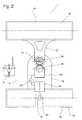
- the in the FIGS. 1 and 2 illustrated and designated 1 device 1 is used for venting a bottom coating 3, which is used to level balance on a screed covering 3 and are included in the air bubbles 4.
- a first venting roller 15 and a second venting roller 16 are rotatably mounted in a housing 11 of the device 1 in this case.
- the two breather rollers 15 bwz.16 are each equipped with spines 17 or loops.
- the first breather roller 15, which is formed divided and provided with a common shaft 18, a preferably electric drive motor 21 is associated with the first breather roller 15 and the common shaft 18 by means of a toothed belt 22 or a chain in drive connection.
- the drive motor 21 is remotely controllable by means of a control unit S, which cooperates with a built-in receiver 11 in the housing 23 via radio or infrared waves.
- the housing 11 is composed of a first and second housing part 12 and 13, which are pivotally connected to each other by means of a pivot pin 14.
- the orientation of the two housing parts 12 and 13 to each other, which can be changed by the pivoting of the housing part 13, is accomplished by means of an adjusting motor 24 which is designed as a reversible electric motor.
- a pinion 25 is driven, which is drivingly connected to gear members 26 on the second housing part 13, so that by the reversible adjusting motor 24, the pivoting of the two housing parts 13 is effected in both directions to a change in the direction of Trigger device 1.
- the adjusting motor 24 can also be operated remotely by means of the control unit S via radio or infrared waves.
- the second venting roller 16 is mounted in the second housing part 13 and thus forms with the first venting roller 12 a three-point support of the housing 11.
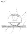
- the two venting rollers 15 and 16 are each interchangeably inserted in cylinder-shaped receiving shells 19 of the two housing parts 12, 13.
- the receiving trays 19 are, like this Fig. 3 it can be seen on the inside preferably adhered panels in the form of films 20 attached.
- the two breather rollers 15 and 16 can thus be easily replaced, for example, for maintenance and cleaning purposes or to replace a breather roller 15, 16 with spikes 5 against a breather roller with loops.
- the films 20 on the inside of the receiving trays 19 without inserted breather rollers 15 and / or 16 can be easily replaced.
- the venting device 1 is self-propelled and remotely controllable. For venting a not yet cured floor coating in a building of the publisher need only set up the device 1 on the bottom coating 3 and set by means of the remote control unit S, which is in radio communication with the receiver 23 to the device 1, the direction and travel speed.
- the drive motor 21 is switchable, so that the device 1 can be moved both forward and backward. Accordingly, the device 1 can be moved remotely over the entire floor coating 3, so that it can be vented in a simple and fast manner.
Landscapes
- Engineering & Computer Science (AREA)
- Architecture (AREA)
- Coating Apparatus (AREA)
- Mechanical Engineering (AREA)
- Civil Engineering (AREA)
- Structural Engineering (AREA)
- Floor Finish (AREA)
Abstract
Description
- Die Erfindung betrifft eine Vorrichtung zum Entlüften von Bodenbeschichtungen, insbesondere von Kunstharzbeschichtungen oder Spachtelmassen, mittels einer in einem Gehäuse drehbar gelagerten Entlüftungswalze, die mit einer Vielzahl von Stacheln bestückt ist.
- Bei der Herstellung von für Bodenbeschichtungen vorgesehenen Kunstharz- oder Spachtelmassen, mittels denen eine Nivelierspachtelung zu bewerkstelligen ist, wird beim Anrühren dieser Massen unumgänglich Luft eingeschlossen, die nach dem Auftragen der Beschichtung in Form von Luftblasen austritt. Vor dem Aushärten der Beschichtung ist diese daher zu entlüften, da durch die Luftblasen die Oberfläche beeinträchtigt wird.
- Die Entlüftung wird bisher manuell durchgeführt, indem eine mit Stacheln versehene Entlüftungswalze, die zur leichteren Handhabung an einem Griff oder an einem Stab befestigt ist, über die Bodenbeschichtung geführt bzw. abgerollt wird. Bei dünnen Bodenbeschichtungen oder zum Entfernen von restlichen Lufteinschlüssen werden auch mit Schlingen versehene Entlüftungswalzen eingesetzt. Um jedoch die mitunter dünnflüssigen Beschichtungen betreten zu können, hat der Bearbeiter vorab an den Schuhen spezielle Nagelsohlen zu befestigen. Die Entlüftung einer Bodenbeschichtung ist somit umständlich und sehr zeitaufwendig.
- Es ist daher Aufgabe der Erfindung, die eingangs genannte Vorrichtung zum Entlüften von Bodenbeschichtungen derart weiterzubilden, dass ein Entlüften einer Beschichtung, ohne diese betreten zu müssen, in sehr kurzer Zeit und auf äußerst einfache Weise möglich ist.
- Diese Aufgabe wird gelöst mit einer Entlüftungsvorrichtung der vorgenannten Gattung, in dem der Entlüftungswalze ein Antriebsmotor zugeordnet ist, der mit dieser in Triebverbindung steht und mittels eines Steuergerätes über Funk oder Infrarotwellen fernbedienbar ist, und dass das Gehäuse der Vorrichtung eine Dreipunktabstützung aufweist.
- Vorzugsweise ist das Gehäuse aus einem ersten und zweiten Gehäuseteil zusammengesetzt, die gelenkig miteinander verbunden sind, wobei zum Verschwenken eines der beiden Gehäuseteile ein Verstellmotor vorzusehen ist, der mittels des Steuergerätes ebenfalls über Funk oder Infrarotwellen fernbedienbar ist. Die gelenkige Verbindung der beiden Gehäuseteile ermöglicht die Änderung der Fahrtrichtung der Vorrichtung.
- In einer weiteren Ausgestaltung ist die antreibbare Entlüftungswalze unterteilt ausgebildet und deren gemeinsame Welle ist in diesem Bereich zwischen den beiden Teilen der Entlüftungswalze mit dem Antriebsmotor trieblich verbunden. Die gemeinsame Welle zwischen den Teilentlüftungswalzen gestattet die einfache triebliche Verbindung zwischen dem Antriebsmotor und der Entlüftungswalze.
- In einer einfachen Ausführungsform ist die Dreipunktabstützung des Gehäuses durch die Entlüftungswalze und eine zweite Entlüftungswalze gebildet, die verdrehbar, vorzugsweise in dem verschwenkbaren zweiten Gehäuseteil gelagert ist.
- Des Weiteren ist vorgesehen, die beiden Gehäuseteile etwa in der Mitte des Gehäuses auf- oder ineinander zu lagern und den verschwenkbaren zweiten Gehäuseteil über einen vertikal angeordneten Gelenkzapfen vorzugsweise mit dem mit dem Antriebsmotor versehenen ersten Gehäuseteil zu verbinden. Die Anordnung des Gelenkzapfens etwa in der Mitte des Gehäuses gestattet eine einfache und effektive Änderung der Fahrtrichtung der Vorrichtung durch das Verschwenken eines der beiden Gehäuseteile.
- Vorzugsweise ist zur Erzeugung der Verstellbewegungen des zweiten Gehäuseteils ein umschaltbarer Elektromotor vorgesehen, der über ein Ritzel oder Zahnstangen mit an dem verschwenkbaren zweiten Gehäuseteil angebrachten Getriebegliedern zusammenwirkt. Der umschaltbare Elektromotor ermöglicht es, Richtungsänderungen rasch und ohne Schwierigkeiten vorzunehmen.
- In einer weiteren Ausgestaltung sind die Entlüftungswalzen jeweils in einer zylinderabschnittsförmig ausgebildeten Aufnahmeschale auswechselbar eingesetzt. Durch die Aufnahmeschalen wird verhindert, dass während des Entlüftungsvorganges Teile der Bodenbeschichtung in die Umgebung der Vorrichtung abgeschleudert werden.
- Zweckmäßig ist es hierbei, die Aufnahmeschalen auf der Innenseite mit auswechselbaren, vorzugsweise angeklebten Verkleidungen in Form von Folien zu versehen. Das Abziehen der Folien gestattet die einfache Reinigung der Innenseiten der Aufnahmeschalen von Resten der Bodenbeschichtung.
- Wird eine Vorrichtung gemäß der Erfindung ausgebildet, so ist es auf einfache Weise und in kurzer Zeit möglich, einen Bodenbelag zu entlüften, ohne dass der Raum, in dem ein derartiger Belag auf einer Decke aufgebracht wurde, betreten werden muss. Vielmehr kann die Vorrichtung von außerhalb des Raumes bedient und mehr oder weniger schnell über den Belag verfahren werden. Durch die Stacheln bzw. die Schlingen wird dabei eine Vielzahl von Löchern in den Belag eingebracht, so dass die eingeschlossene Luft zuverlässig entweichen kann. Das Entlüften einer Bodenbeschichtung mit Hilfe der vorschlagsgemäß ausgebildeten Vorrichtung ist somit als angenehme Unterbrechung von oftmals körperlich schweren Arbeiten anzusehen.
- In den Zeichnungen ist ein Ausführungsbeispiel der gemäß der Erfindung ausgebildeten Vorrichtung zum Entlüftung von Bodenbeschichtungen dargestellt und nachfolgend im Einzelnen erläutert. Hierbei zeigt:
- Figur 1
- die Vorrichtung, in Seitenansicht,
- Figur 2
- die Vorrichtung nach
Figur 1 , in Draufsicht und - Figur 3
- einen Ausschnitt aus
Figur 1 in vergrößerter Darstellung. - Die in den
Figuren 1 und2 dargestellte und mit 1 bezeichnete Vorrichtung 1 dient zum Entlüften einer Bodenbeschichtung 3, die zum Niveauausgleich auf einem Estrichbelag 3 aufgebraucht ist und in der Luftblasen 4 eingeschlossen sind. In einem Gehäuse 11 der Vorrichtung 1 sind hierbei eine erste Entlüftungswalze 15 und eine zweite Entlüftungswalze 16 verdrehbar gelagert. Die beiden Entlüftungswalzen 15 bwz.16 sind jeweils mit Stacheln 17 oder Schlingen bestückt. Der ersten Entlüftungswalze 15, die unterteilt ausgebildet und mit einer gemeinsamen Welle 18 versehen ist, ist ein vorzugsweise elektrischer Antriebsmotor 21 zugeordnet, der mit der ersten Entlüftungswalze 15 bzw. der gemeinsamen Welle 18 mittels eines Zahnriemens 22 oder einer Kette in Triebverbindung steht. Der Antriebsmotor 21 ist mittels eines Steuergerätes S, das mit einem in das Gehäuse 11 eingebauten Empfänger 23 zusammenwirkt, über Funk oder Infrarotwellen fernbedienbar. - Das Gehäuse 11 ist aus einem ersten und zweiten Gehäuseteil 12 bzw. 13 zusammengesetzt, die mittels eines Gelenkzapfens 14 verschwenkbar miteinander verbunden sind. Die Ausrichtung der beiden Gehäuseteile 12 bzw. 13 zueinander, die durch das Verschwenken des Gehäuseteiles 13 verändert werden kann, wird mit Hilfe eines Verstellmotor 24, der als umschaltbarer Elektromotor ausgebildet ist, bewerkstelligt. Von dem Verstellmotor 24 wird hierbei ein Ritzel 25 angetrieben, das trieblich mit Getriebegliedern 26 am zweiten Gehäuseteil 13 verbunden ist, so dass durch den umschaltbaren Verstellmotor 24 das Verschwenken der beiden Gehäuseteile 13 in beide Richtungen bewirkt wird, um eine Änderung der Fahrtrichtung der Vorrichtung 1 auszulösen. Der Verstellmotor 24 ist ebenfalls mittels des Steuergerätes S über Funk oder Infrarotwellen fernbedienbar.
- Die zweite Entlüftungswalze 16 ist im zweiten Gehäuseteil 13 gelagert und bildet damit mit der ersten Entlüftungswalze 12 eine Dreipunktabstützung des Gehäuses 11. Die beiden Entlüftungswalzen 15 und 16 sind jeweils in zylinderabschnittsförmigen Aufnahmeschalen 19 der beiden Gehäuseteile 12, 13 auswechselbar eingesetzt.
- In den Aufnahmeschalen 19 sind, wie dies der
Fig. 3 zu entnehmen ist, auf der Innenseite vorzugsweise angeklebte Verkleidungen in Form von Folien 20 angebracht. Die beiden Entlüftungswalzen 15 und 16 können somit leicht ausgetauscht werden, beispielsweise zu Wartungs- und Reinigungszwecken oder zum Austausch einer Entlüftungswalze 15, 16 mit Stacheln 5 gegen eine Entlüftungswalze mit Schlingen. Darüber hinaus können die Folien 20 auf der Innenseite der Aufnahmeschalen 19 ohne eingesetzte Entlüftungswalzen 15 und/oder 16 leicht ausgetauscht werden. - Nach dem Entlüften der Bodenbeschichtung 3 befinden sich an der Innenseite der Aufnahmeschalen 19 oftmals Reste der Bodenbeschichtung. Durch das Abziehen der Folie 20 können diese Reste rasch entfernt werden, so dass eine aufwendige Reinigung der Aufnahmeschalen 19 nach der Benutzung der Vorrichtung 1 nicht erforderlich ist.
- Die Entlüftungsvorrichtung 1 ist selbstfahrend und fernsteuerbar. Zum Entlüften einer noch nicht ausgehärteten Bodenbeschichtung in einem Gebäude braucht der Verleger lediglich die Vorrichtung 1 auf die Bodenbeschichtung 3 aufzusetzen und mittels des Fernsteuergerätes S, das in Funkverbindung mit dem Empfänger 23 an der Vorrichtung 1 steht, die Richtung und Fahrgeschwindigkeit einzustellen. Der Antriebsmotor 21 ist umschaltbar, so dass die Vorrichtung 1 sowohl vorwärts als auch rückwärts verfahren werden kann. Die Vorrichtung 1 ist demnach ferngesteuert über die gesamte Bodenbeschichtung 3 verfahrbar, so dass diese in einfacher und schneller Weise zu entlüften ist.
Claims (8)
- Vorrichtung (1) zum Entlüften von Bodenbeschichtungen (3), insbesondere von Kunstharzbeschichtungen oder Spachtelmassen, mittels einer in einem Gehäuse (11) drehbar gelagerten Entlüftungswalze (15), die mit einer Vielzahl von Stacheln (17) bestückt ist,
dadurch gekennzeichnet,
dass der Entlüftungswalze (15) ein Antriebsmotor (21) zugeordnet ist, der mit dieser in Triebverbindung steht und mittels eines Steuergerätes S über Funk oder Infrarotwellen fernbedienbar ist, und dass das Gehäuse (11) der Vorrichtung (1) eine Dreipunktabstützung aufweist. - Vorrichtung nach Anspruch 1,
dadurch gekennzeichnet,
dass das Gehäuse (11) aus einem ersten und zweiten Gehäuseteil (12, 13) zusammengesetzt ist, die gelenkig miteinander verbunden sind, und dass zum Verschwenken eines der beiden Gehäuseteile (13) ein Verstellmotor (24) vorgesehen ist, der mittels des Steuergerätes S über Funk oder Infrarotwellen fernbedienbar ist. - Vorrichtung nach Anspruch 1 oder 2,
dadurch gekennzeichnet,
dass die antreibbare Entlüftungswalze (15) unterteilt ausgebildet ist und dass deren gemeinsame Welle (18) in dem Bereich zwischen den beiden Teilen der Entlüftungswalze (15) mit dem Antriebsmotor (21) trieblich verbunden ist. - Vorrichtung nach einem oder mehreren der Ansprüche 1 bis 3,
dadurch gekennzeichnet,
dass die Dreipunktabstützung des Gehäuses (11) durch die Entlüftungswalze (15) und eine zweite Entlüftungswalze (16) gebildet ist, die verdrehbar, vorzugsweise in dem verschwenkbaren zweiten Gehäuseteil (13), gelagert ist. - Vorrichtung nach einem oder mehreren der Ansprüche 1 bis 4,
dadurch gekennzeichnet,
dass die beiden Gehäuseteile (12,13) etwa in der Mitte des Gehäuses (12) auf- oder ineinander gelagert sind und dass der verschwenkbare zweite Gehäuseteil (13) über einen vertikal angeordneten Gelenkzapfen (14), vorzugsweise mit dem mit dem Antriebsmotor (21) versehenen ersten Gehäuseteil (12), verbunden ist. - Vorrichtung nach einem oder mehreren der Ansprüche 1 bis 5,
dadurch gekennzeichnet,
dass zur Erzeugung der Verstellbewegungen des zweiten Gehäuseteils (13) ein umschaltbarer Elektromotor (24) vorgesehen ist, der über ein Ritzel (25) oder Zahnstangen mit an dem verschwenkbaren zweiten Gehäuseteil (13) angebrachten Getriebegliedern (26) zusammenwirkt. - Vorrichtung nach einem oder mehreren der Ansprüche 1 bis 6,
dadurch gekennzeichnet,
dass die Entlüftungswalzen (15, 16) jeweils in einer zylinderabschnittsförmig ausgebildeten Aufnahmeschale (19) auswechselbar eingesetzt sind. - Vorrichtung nach Anspruch 7,
dadurch gekennzeichnet,
dass die Aufnahmeschalen (19) auf der Innenseite mit auswechselbaren, vorzugsweise angeklebten Verkleidungen in Form von Folien versehen sind.
Applications Claiming Priority (1)
| Application Number | Priority Date | Filing Date | Title |
|---|---|---|---|
| DE202007006144U DE202007006144U1 (de) | 2007-04-28 | 2007-04-28 | Vorrichtung zum Entlüften von Bodenbeschichtungen |
Publications (3)
| Publication Number | Publication Date |
|---|---|
| EP1985378A2 true EP1985378A2 (de) | 2008-10-29 |
| EP1985378A3 EP1985378A3 (de) | 2008-11-26 |
| EP1985378B1 EP1985378B1 (de) | 2010-09-22 |
Family
ID=39577787
Family Applications (1)
| Application Number | Title | Priority Date | Filing Date |
|---|---|---|---|
| EP08004131A Not-in-force EP1985378B1 (de) | 2007-04-28 | 2008-03-06 | Vorrichtung zum Entlüften von Bodenbeschichtungen |
Country Status (3)
| Country | Link |
|---|---|
| EP (1) | EP1985378B1 (de) |
| AT (1) | ATE481865T1 (de) |
| DE (2) | DE202007006144U1 (de) |
Cited By (1)
| Publication number | Priority date | Publication date | Assignee | Title |
|---|---|---|---|---|
| CN113530148A (zh) * | 2021-07-31 | 2021-10-22 | 中冶建工集团有限公司 | 一种混凝土地坪的浇筑方法 |
Families Citing this family (1)
| Publication number | Priority date | Publication date | Assignee | Title |
|---|---|---|---|---|
| CN112127244A (zh) * | 2020-10-19 | 2020-12-25 | 嵊州米想道路设施有限公司 | 一种自动排砖的路面铺砖装置 |
Family Cites Families (4)
| Publication number | Priority date | Publication date | Assignee | Title |
|---|---|---|---|---|
| DE4323580C1 (de) * | 1993-07-14 | 1995-03-23 | Elias Lebessis | Reißwerkzeug |
| DE19817614A1 (de) * | 1998-04-21 | 1999-11-04 | Kvs Korrosions Und Verschleiss | Verfahren zum Beschichten eines Bodens |
| US7232277B2 (en) * | 2002-08-02 | 2007-06-19 | Chris Corbitt | Remotely-controlled concrete tool assembly |
| US20070006404A1 (en) * | 2005-07-08 | 2007-01-11 | Gooten Innolife Corporation | Remote control sweeper |
-
2007
- 2007-04-28 DE DE202007006144U patent/DE202007006144U1/de not_active Expired - Lifetime
-
2008
- 2008-03-06 DE DE502008001353T patent/DE502008001353D1/de active Active
- 2008-03-06 EP EP08004131A patent/EP1985378B1/de not_active Not-in-force
- 2008-03-06 AT AT08004131T patent/ATE481865T1/de active
Cited By (1)
| Publication number | Priority date | Publication date | Assignee | Title |
|---|---|---|---|---|
| CN113530148A (zh) * | 2021-07-31 | 2021-10-22 | 中冶建工集团有限公司 | 一种混凝土地坪的浇筑方法 |
Also Published As
| Publication number | Publication date |
|---|---|
| DE202007006144U1 (de) | 2008-09-04 |
| ATE481865T1 (de) | 2010-10-15 |
| DE502008001353D1 (de) | 2010-11-04 |
| EP1985378A3 (de) | 2008-11-26 |
| EP1985378B1 (de) | 2010-09-22 |
Similar Documents
| Publication | Publication Date | Title |
|---|---|---|
| DE2818073C2 (de) | Tragbares Gerät zum Ablösen von auf einem Untergrund haftenden Bodenbelägen, Tapeten oder dergleichen | |
| DE2434716A1 (de) | Ballwurfgeraet | |
| WO2016173756A1 (de) | Roboterwerkzeug zum setzen von stopfen | |
| DE102010008309A1 (de) | Schwingungsreduzierte Führungsvorrichtung | |
| EP1987891B1 (de) | Kanten-Anleimvorrichtung | |
| EP1985378B1 (de) | Vorrichtung zum Entlüften von Bodenbeschichtungen | |
| DE2610904A1 (de) | Foerdereinrichtung fuer stueckgueter, insbesondere bretter | |
| DE3006039C2 (de) | Verfahren und Vorrichtung zum Herstellen von auf vorhandene Bootsdecks aufzubringenden Stabdecks | |
| WO2017139819A1 (de) | Abkantpresse und verfahren zum wechseln von biegewerkzeugen einer abkantpresse | |
| EP2182115A1 (de) | Schotterplaniervorrichtung | |
| DE102011114177B4 (de) | Schutzabdeckung mit Rückhaltevorrichtung | |
| DE102019120375B3 (de) | Verfahren zum Betreiben einer Vorrichtung zur Bearbeitung, insbesondere Schmalseitenbearbeitung, von plattenförmigen Werkstücken | |
| EP1396438B1 (de) | Vorrichtung zur Halterung von Klemmschellen in einer vorbestimmten Lage | |
| EP3434844B1 (de) | Mörtelschlitten | |
| EP2907635A1 (de) | Kantenfräsvorrichtung und Verfahren zum Fräsen einer Kante | |
| EP4047133A1 (de) | Pistenraupe mit wenigstens einem pistenbearbeitungsgerät | |
| DE202017103170U1 (de) | Vorrichtung zum Töpfern | |
| DE19605577A1 (de) | Verfahren und Vorrichtung zum Verlegen von Bodenbelägen | |
| DE9013654U1 (de) | Stanzmaschine | |
| DE2928428C2 (de) | ||
| DE3050730C2 (de) | Schneidvorrichtung fuer holzbauteile | |
| DE102010028683A1 (de) | Füllmaschine zum Abfüllen pastöser Masse | |
| DE10127725A1 (de) | Heckenschneidevorrichtung | |
| DE2329544C2 (de) | Vorrichtung zum maschinellen Verdichten und Ebnen von Estrichmassen | |
| DE202018004321U1 (de) | Tor |
Legal Events
| Date | Code | Title | Description |
|---|---|---|---|
| PUAI | Public reference made under article 153(3) epc to a published international application that has entered the european phase |
Free format text: ORIGINAL CODE: 0009012 |
|
| PUAL | Search report despatched |
Free format text: ORIGINAL CODE: 0009013 |
|
| AK | Designated contracting states |
Kind code of ref document: A2 Designated state(s): AT BE BG CH CY CZ DE DK EE ES FI FR GB GR HR HU IE IS IT LI LT LU LV MC MT NL NO PL PT RO SE SI SK TR |
|
| AX | Request for extension of the european patent |
Extension state: AL BA MK RS |
|
| AK | Designated contracting states |
Kind code of ref document: A3 Designated state(s): AT BE BG CH CY CZ DE DK EE ES FI FR GB GR HR HU IE IS IT LI LT LU LV MC MT NL NO PL PT RO SE SI SK TR |
|
| AX | Request for extension of the european patent |
Extension state: AL BA MK RS |
|
| RIC1 | Information provided on ipc code assigned before grant |
Ipc: A01D 41/00 20060101ALI20081023BHEP Ipc: E04F 21/20 20060101ALI20081023BHEP Ipc: B05D 3/12 20060101ALI20081023BHEP Ipc: A47L 11/32 20060101ALI20081023BHEP Ipc: A01D 37/00 20060101AFI20081023BHEP Ipc: A47L 11/33 20060101ALI20081023BHEP Ipc: C04B 41/48 20060101ALI20081023BHEP Ipc: A01D 42/00 20060101ALI20081023BHEP Ipc: E04F 21/22 20060101ALI20081023BHEP Ipc: A01D 39/00 20060101ALI20081023BHEP Ipc: E04F 21/00 20060101ALI20081023BHEP Ipc: E04F 15/12 20060101ALI20081023BHEP Ipc: E04F 21/24 20060101ALI20081023BHEP Ipc: B44C 7/02 20060101ALI20081023BHEP Ipc: A63H 30/04 20060101ALI20081023BHEP |
|
| 17P | Request for examination filed |
Effective date: 20090514 |
|
| AKX | Designation fees paid |
Designated state(s): AT BE BG CH CY CZ DE DK EE ES FI FR GB GR HR HU IE IS IT LI LT LU LV MC MT NL NO PL PT RO SE SI SK TR |
|
| 17Q | First examination report despatched |
Effective date: 20090723 |
|
| GRAP | Despatch of communication of intention to grant a patent |
Free format text: ORIGINAL CODE: EPIDOSNIGR1 |
|
| GRAS | Grant fee paid |
Free format text: ORIGINAL CODE: EPIDOSNIGR3 |
|
| GRAA | (expected) grant |
Free format text: ORIGINAL CODE: 0009210 |
|
| AK | Designated contracting states |
Kind code of ref document: B1 Designated state(s): AT BE BG CH CY CZ DE DK EE ES FI FR GB GR HR HU IE IS IT LI LT LU LV MC MT NL NO PL PT RO SE SI SK TR |
|
| REG | Reference to a national code |
Ref country code: GB Ref legal event code: FG4D Free format text: NOT ENGLISH |
|
| REG | Reference to a national code |
Ref country code: CH Ref legal event code: EP |
|
| REG | Reference to a national code |
Ref country code: IE Ref legal event code: FG4D Free format text: LANGUAGE OF EP DOCUMENT: GERMAN |
|
| REF | Corresponds to: |
Ref document number: 502008001353 Country of ref document: DE Date of ref document: 20101104 Kind code of ref document: P |
|
| PG25 | Lapsed in a contracting state [announced via postgrant information from national office to epo] |
Ref country code: NO Free format text: LAPSE BECAUSE OF FAILURE TO SUBMIT A TRANSLATION OF THE DESCRIPTION OR TO PAY THE FEE WITHIN THE PRESCRIBED TIME-LIMIT Effective date: 20101222 Ref country code: FI Free format text: LAPSE BECAUSE OF FAILURE TO SUBMIT A TRANSLATION OF THE DESCRIPTION OR TO PAY THE FEE WITHIN THE PRESCRIBED TIME-LIMIT Effective date: 20100922 Ref country code: LT Free format text: LAPSE BECAUSE OF FAILURE TO SUBMIT A TRANSLATION OF THE DESCRIPTION OR TO PAY THE FEE WITHIN THE PRESCRIBED TIME-LIMIT Effective date: 20100922 |
|
| REG | Reference to a national code |
Ref country code: NL Ref legal event code: VDEP Effective date: 20100922 |
|
| LTIE | Lt: invalidation of european patent or patent extension |
Effective date: 20100922 |
|
| PG25 | Lapsed in a contracting state [announced via postgrant information from national office to epo] |
Ref country code: PL Free format text: LAPSE BECAUSE OF FAILURE TO SUBMIT A TRANSLATION OF THE DESCRIPTION OR TO PAY THE FEE WITHIN THE PRESCRIBED TIME-LIMIT Effective date: 20100922 Ref country code: SI Free format text: LAPSE BECAUSE OF FAILURE TO SUBMIT A TRANSLATION OF THE DESCRIPTION OR TO PAY THE FEE WITHIN THE PRESCRIBED TIME-LIMIT Effective date: 20100922 Ref country code: HR Free format text: LAPSE BECAUSE OF FAILURE TO SUBMIT A TRANSLATION OF THE DESCRIPTION OR TO PAY THE FEE WITHIN THE PRESCRIBED TIME-LIMIT Effective date: 20100922 |
|
| PG25 | Lapsed in a contracting state [announced via postgrant information from national office to epo] |
Ref country code: SE Free format text: LAPSE BECAUSE OF FAILURE TO SUBMIT A TRANSLATION OF THE DESCRIPTION OR TO PAY THE FEE WITHIN THE PRESCRIBED TIME-LIMIT Effective date: 20100922 Ref country code: GR Free format text: LAPSE BECAUSE OF FAILURE TO SUBMIT A TRANSLATION OF THE DESCRIPTION OR TO PAY THE FEE WITHIN THE PRESCRIBED TIME-LIMIT Effective date: 20101223 Ref country code: LV Free format text: LAPSE BECAUSE OF FAILURE TO SUBMIT A TRANSLATION OF THE DESCRIPTION OR TO PAY THE FEE WITHIN THE PRESCRIBED TIME-LIMIT Effective date: 20100922 |
|
| REG | Reference to a national code |
Ref country code: IE Ref legal event code: FD4D |
|
| PG25 | Lapsed in a contracting state [announced via postgrant information from national office to epo] |
Ref country code: IE Free format text: LAPSE BECAUSE OF FAILURE TO SUBMIT A TRANSLATION OF THE DESCRIPTION OR TO PAY THE FEE WITHIN THE PRESCRIBED TIME-LIMIT Effective date: 20100922 |
|
| PG25 | Lapsed in a contracting state [announced via postgrant information from national office to epo] |
Ref country code: EE Free format text: LAPSE BECAUSE OF FAILURE TO SUBMIT A TRANSLATION OF THE DESCRIPTION OR TO PAY THE FEE WITHIN THE PRESCRIBED TIME-LIMIT Effective date: 20100922 Ref country code: PT Free format text: LAPSE BECAUSE OF FAILURE TO SUBMIT A TRANSLATION OF THE DESCRIPTION OR TO PAY THE FEE WITHIN THE PRESCRIBED TIME-LIMIT Effective date: 20110124 Ref country code: SK Free format text: LAPSE BECAUSE OF FAILURE TO SUBMIT A TRANSLATION OF THE DESCRIPTION OR TO PAY THE FEE WITHIN THE PRESCRIBED TIME-LIMIT Effective date: 20100922 Ref country code: NL Free format text: LAPSE BECAUSE OF FAILURE TO SUBMIT A TRANSLATION OF THE DESCRIPTION OR TO PAY THE FEE WITHIN THE PRESCRIBED TIME-LIMIT Effective date: 20100922 Ref country code: RO Free format text: LAPSE BECAUSE OF FAILURE TO SUBMIT A TRANSLATION OF THE DESCRIPTION OR TO PAY THE FEE WITHIN THE PRESCRIBED TIME-LIMIT Effective date: 20100922 Ref country code: CZ Free format text: LAPSE BECAUSE OF FAILURE TO SUBMIT A TRANSLATION OF THE DESCRIPTION OR TO PAY THE FEE WITHIN THE PRESCRIBED TIME-LIMIT Effective date: 20100922 Ref country code: IS Free format text: LAPSE BECAUSE OF FAILURE TO SUBMIT A TRANSLATION OF THE DESCRIPTION OR TO PAY THE FEE WITHIN THE PRESCRIBED TIME-LIMIT Effective date: 20110122 Ref country code: IT Free format text: LAPSE BECAUSE OF FAILURE TO SUBMIT A TRANSLATION OF THE DESCRIPTION OR TO PAY THE FEE WITHIN THE PRESCRIBED TIME-LIMIT Effective date: 20100922 |
|
| PG25 | Lapsed in a contracting state [announced via postgrant information from national office to epo] |
Ref country code: ES Free format text: LAPSE BECAUSE OF FAILURE TO SUBMIT A TRANSLATION OF THE DESCRIPTION OR TO PAY THE FEE WITHIN THE PRESCRIBED TIME-LIMIT Effective date: 20110102 |
|
| PLBE | No opposition filed within time limit |
Free format text: ORIGINAL CODE: 0009261 |
|
| STAA | Information on the status of an ep patent application or granted ep patent |
Free format text: STATUS: NO OPPOSITION FILED WITHIN TIME LIMIT |
|
| 26N | No opposition filed |
Effective date: 20110623 |
|
| PG25 | Lapsed in a contracting state [announced via postgrant information from national office to epo] |
Ref country code: DK Free format text: LAPSE BECAUSE OF FAILURE TO SUBMIT A TRANSLATION OF THE DESCRIPTION OR TO PAY THE FEE WITHIN THE PRESCRIBED TIME-LIMIT Effective date: 20100922 |
|
| BERE | Be: lapsed |
Owner name: REUTER, WERNER Effective date: 20110331 |
|
| REG | Reference to a national code |
Ref country code: DE Ref legal event code: R097 Ref document number: 502008001353 Country of ref document: DE Effective date: 20110623 |
|
| PG25 | Lapsed in a contracting state [announced via postgrant information from national office to epo] |
Ref country code: MC Free format text: LAPSE BECAUSE OF NON-PAYMENT OF DUE FEES Effective date: 20110331 |
|
| REG | Reference to a national code |
Ref country code: FR Ref legal event code: ST Effective date: 20111130 |
|
| PG25 | Lapsed in a contracting state [announced via postgrant information from national office to epo] |
Ref country code: MT Free format text: LAPSE BECAUSE OF FAILURE TO SUBMIT A TRANSLATION OF THE DESCRIPTION OR TO PAY THE FEE WITHIN THE PRESCRIBED TIME-LIMIT Effective date: 20100922 Ref country code: BE Free format text: LAPSE BECAUSE OF NON-PAYMENT OF DUE FEES Effective date: 20110331 |
|
| PG25 | Lapsed in a contracting state [announced via postgrant information from national office to epo] |
Ref country code: FR Free format text: LAPSE BECAUSE OF NON-PAYMENT OF DUE FEES Effective date: 20110331 |
|
| REG | Reference to a national code |
Ref country code: CH Ref legal event code: PL |
|
| GBPC | Gb: european patent ceased through non-payment of renewal fee |
Effective date: 20120306 |
|
| PG25 | Lapsed in a contracting state [announced via postgrant information from national office to epo] |
Ref country code: LI Free format text: LAPSE BECAUSE OF NON-PAYMENT OF DUE FEES Effective date: 20120331 Ref country code: GB Free format text: LAPSE BECAUSE OF NON-PAYMENT OF DUE FEES Effective date: 20120306 Ref country code: CH Free format text: LAPSE BECAUSE OF NON-PAYMENT OF DUE FEES Effective date: 20120331 |
|
| PG25 | Lapsed in a contracting state [announced via postgrant information from national office to epo] |
Ref country code: CY Free format text: LAPSE BECAUSE OF FAILURE TO SUBMIT A TRANSLATION OF THE DESCRIPTION OR TO PAY THE FEE WITHIN THE PRESCRIBED TIME-LIMIT Effective date: 20100922 Ref country code: LU Free format text: LAPSE BECAUSE OF NON-PAYMENT OF DUE FEES Effective date: 20110306 |
|
| PG25 | Lapsed in a contracting state [announced via postgrant information from national office to epo] |
Ref country code: BG Free format text: LAPSE BECAUSE OF FAILURE TO SUBMIT A TRANSLATION OF THE DESCRIPTION OR TO PAY THE FEE WITHIN THE PRESCRIBED TIME-LIMIT Effective date: 20101222 Ref country code: TR Free format text: LAPSE BECAUSE OF FAILURE TO SUBMIT A TRANSLATION OF THE DESCRIPTION OR TO PAY THE FEE WITHIN THE PRESCRIBED TIME-LIMIT Effective date: 20100922 |
|
| PG25 | Lapsed in a contracting state [announced via postgrant information from national office to epo] |
Ref country code: HU Free format text: LAPSE BECAUSE OF FAILURE TO SUBMIT A TRANSLATION OF THE DESCRIPTION OR TO PAY THE FEE WITHIN THE PRESCRIBED TIME-LIMIT Effective date: 20100922 |
|
| REG | Reference to a national code |
Ref country code: AT Ref legal event code: MM01 Ref document number: 481865 Country of ref document: AT Kind code of ref document: T Effective date: 20130306 |
|
| PG25 | Lapsed in a contracting state [announced via postgrant information from national office to epo] |
Ref country code: AT Free format text: LAPSE BECAUSE OF NON-PAYMENT OF DUE FEES Effective date: 20130306 |
|
| PGFP | Annual fee paid to national office [announced via postgrant information from national office to epo] |
Ref country code: DE Payment date: 20160428 Year of fee payment: 9 |
|
| REG | Reference to a national code |
Ref country code: DE Ref legal event code: R119 Ref document number: 502008001353 Country of ref document: DE |
|
| PG25 | Lapsed in a contracting state [announced via postgrant information from national office to epo] |
Ref country code: DE Free format text: LAPSE BECAUSE OF NON-PAYMENT OF DUE FEES Effective date: 20171003 |