EP1980888A1 - Objectif à infrarouge, appareil de prise de vue à infrarouge et vision nocturne - Google Patents
Objectif à infrarouge, appareil de prise de vue à infrarouge et vision nocturne Download PDFInfo
- Publication number
- EP1980888A1 EP1980888A1 EP06823099A EP06823099A EP1980888A1 EP 1980888 A1 EP1980888 A1 EP 1980888A1 EP 06823099 A EP06823099 A EP 06823099A EP 06823099 A EP06823099 A EP 06823099A EP 1980888 A1 EP1980888 A1 EP 1980888A1
- Authority
- EP
- European Patent Office
- Prior art keywords
- lens
- infrared
- lenses
- configuration
- groups
- Prior art date
- Legal status (The legal status is an assumption and is not a legal conclusion. Google has not performed a legal analysis and makes no representation as to the accuracy of the status listed.)
- Withdrawn
Links
- 230000004297 night vision Effects 0.000 title claims description 19
- 238000000465 moulding Methods 0.000 claims abstract description 50
- 239000005083 Zinc sulfide Substances 0.000 claims abstract description 44
- 229910052984 zinc sulfide Inorganic materials 0.000 claims abstract description 44
- DRDVZXDWVBGGMH-UHFFFAOYSA-N zinc;sulfide Chemical compound [S-2].[Zn+2] DRDVZXDWVBGGMH-UHFFFAOYSA-N 0.000 claims abstract description 44
- 230000005499 meniscus Effects 0.000 claims abstract description 24
- 239000000843 powder Substances 0.000 claims abstract description 14
- 238000003384 imaging method Methods 0.000 claims description 61
- 230000014509 gene expression Effects 0.000 claims description 34
- 230000002093 peripheral effect Effects 0.000 claims description 5
- 239000002131 composite material Substances 0.000 claims description 3
- 230000004075 alteration Effects 0.000 description 67
- 238000010586 diagram Methods 0.000 description 52
- 238000000034 method Methods 0.000 description 43
- 230000008569 process Effects 0.000 description 37
- 230000005540 biological transmission Effects 0.000 description 24
- 201000009310 astigmatism Diseases 0.000 description 21
- 238000000576 coating method Methods 0.000 description 19
- 239000011295 pitch Substances 0.000 description 18
- 230000007423 decrease Effects 0.000 description 17
- 239000000463 material Substances 0.000 description 15
- 238000000926 separation method Methods 0.000 description 15
- 238000009826 distribution Methods 0.000 description 14
- 238000004519 manufacturing process Methods 0.000 description 12
- 230000003287 optical effect Effects 0.000 description 12
- 239000011248 coating agent Substances 0.000 description 8
- 238000009434 installation Methods 0.000 description 8
- 238000002834 transmittance Methods 0.000 description 7
- HMUNWXXNJPVALC-UHFFFAOYSA-N 1-[4-[2-(2,3-dihydro-1H-inden-2-ylamino)pyrimidin-5-yl]piperazin-1-yl]-2-(2,4,6,7-tetrahydrotriazolo[4,5-c]pyridin-5-yl)ethanone Chemical compound C1C(CC2=CC=CC=C12)NC1=NC=C(C=N1)N1CCN(CC1)C(CN1CC2=C(CC1)NN=N2)=O HMUNWXXNJPVALC-UHFFFAOYSA-N 0.000 description 6
- VZSRBBMJRBPUNF-UHFFFAOYSA-N 2-(2,3-dihydro-1H-inden-2-ylamino)-N-[3-oxo-3-(2,4,6,7-tetrahydrotriazolo[4,5-c]pyridin-5-yl)propyl]pyrimidine-5-carboxamide Chemical compound C1C(CC2=CC=CC=C12)NC1=NC=C(C=N1)C(=O)NCCC(N1CC2=C(CC1)NN=N2)=O VZSRBBMJRBPUNF-UHFFFAOYSA-N 0.000 description 6
- LDXJRKWFNNFDSA-UHFFFAOYSA-N 2-(2,4,6,7-tetrahydrotriazolo[4,5-c]pyridin-5-yl)-1-[4-[2-[[3-(trifluoromethoxy)phenyl]methylamino]pyrimidin-5-yl]piperazin-1-yl]ethanone Chemical compound C1CN(CC2=NNN=C21)CC(=O)N3CCN(CC3)C4=CN=C(N=C4)NCC5=CC(=CC=C5)OC(F)(F)F LDXJRKWFNNFDSA-UHFFFAOYSA-N 0.000 description 6
- YLZOPXRUQYQQID-UHFFFAOYSA-N 3-(2,4,6,7-tetrahydrotriazolo[4,5-c]pyridin-5-yl)-1-[4-[2-[[3-(trifluoromethoxy)phenyl]methylamino]pyrimidin-5-yl]piperazin-1-yl]propan-1-one Chemical compound N1N=NC=2CN(CCC=21)CCC(=O)N1CCN(CC1)C=1C=NC(=NC=1)NCC1=CC(=CC=C1)OC(F)(F)F YLZOPXRUQYQQID-UHFFFAOYSA-N 0.000 description 6
- DEXFNLNNUZKHNO-UHFFFAOYSA-N 6-[3-[4-[2-(2,3-dihydro-1H-inden-2-ylamino)pyrimidin-5-yl]piperidin-1-yl]-3-oxopropyl]-3H-1,3-benzoxazol-2-one Chemical compound C1C(CC2=CC=CC=C12)NC1=NC=C(C=N1)C1CCN(CC1)C(CCC1=CC2=C(NC(O2)=O)C=C1)=O DEXFNLNNUZKHNO-UHFFFAOYSA-N 0.000 description 6
- XKRFYHLGVUSROY-UHFFFAOYSA-N Argon Chemical compound [Ar] XKRFYHLGVUSROY-UHFFFAOYSA-N 0.000 description 6
- MKYBYDHXWVHEJW-UHFFFAOYSA-N N-[1-oxo-1-(2,4,6,7-tetrahydrotriazolo[4,5-c]pyridin-5-yl)propan-2-yl]-2-[[3-(trifluoromethoxy)phenyl]methylamino]pyrimidine-5-carboxamide Chemical compound O=C(C(C)NC(=O)C=1C=NC(=NC=1)NCC1=CC(=CC=C1)OC(F)(F)F)N1CC2=C(CC1)NN=N2 MKYBYDHXWVHEJW-UHFFFAOYSA-N 0.000 description 6
- NIPNSKYNPDTRPC-UHFFFAOYSA-N N-[2-oxo-2-(2,4,6,7-tetrahydrotriazolo[4,5-c]pyridin-5-yl)ethyl]-2-[[3-(trifluoromethoxy)phenyl]methylamino]pyrimidine-5-carboxamide Chemical compound O=C(CNC(=O)C=1C=NC(=NC=1)NCC1=CC(=CC=C1)OC(F)(F)F)N1CC2=C(CC1)NN=N2 NIPNSKYNPDTRPC-UHFFFAOYSA-N 0.000 description 6
- AFCARXCZXQIEQB-UHFFFAOYSA-N N-[3-oxo-3-(2,4,6,7-tetrahydrotriazolo[4,5-c]pyridin-5-yl)propyl]-2-[[3-(trifluoromethoxy)phenyl]methylamino]pyrimidine-5-carboxamide Chemical compound O=C(CCNC(=O)C=1C=NC(=NC=1)NCC1=CC(=CC=C1)OC(F)(F)F)N1CC2=C(CC1)NN=N2 AFCARXCZXQIEQB-UHFFFAOYSA-N 0.000 description 6
- 230000008859 change Effects 0.000 description 6
- 230000000052 comparative effect Effects 0.000 description 6
- 230000004438 eyesight Effects 0.000 description 4
- 229910052786 argon Inorganic materials 0.000 description 3
- 230000008901 benefit Effects 0.000 description 3
- 239000011247 coating layer Substances 0.000 description 3
- 238000001816 cooling Methods 0.000 description 3
- 239000000428 dust Substances 0.000 description 3
- 229910052732 germanium Inorganic materials 0.000 description 3
- GNPVGFCGXDBREM-UHFFFAOYSA-N germanium atom Chemical compound [Ge] GNPVGFCGXDBREM-UHFFFAOYSA-N 0.000 description 3
- 238000000227 grinding Methods 0.000 description 3
- 230000006872 improvement Effects 0.000 description 3
- 239000011261 inert gas Substances 0.000 description 3
- 238000010297 mechanical methods and process Methods 0.000 description 3
- 230000005226 mechanical processes and functions Effects 0.000 description 3
- 230000001590 oxidative effect Effects 0.000 description 3
- 239000002245 particle Substances 0.000 description 3
- 238000005498 polishing Methods 0.000 description 3
- 230000009467 reduction Effects 0.000 description 3
- 230000035945 sensitivity Effects 0.000 description 3
- 230000008685 targeting Effects 0.000 description 3
- OKTJSMMVPCPJKN-UHFFFAOYSA-N Carbon Chemical compound [C] OKTJSMMVPCPJKN-UHFFFAOYSA-N 0.000 description 2
- 229910052799 carbon Inorganic materials 0.000 description 2
- 239000012634 fragment Substances 0.000 description 2
- 231100000241 scar Toxicity 0.000 description 2
- 241000282412 Homo Species 0.000 description 1
- 238000010521 absorption reaction Methods 0.000 description 1
- 238000005520 cutting process Methods 0.000 description 1
- 230000000694 effects Effects 0.000 description 1
- 238000005516 engineering process Methods 0.000 description 1
- 239000004973 liquid crystal related substance Substances 0.000 description 1
Images


Classifications
-
- G—PHYSICS
- G02—OPTICS
- G02B—OPTICAL ELEMENTS, SYSTEMS OR APPARATUS
- G02B13/00—Optical objectives specially designed for the purposes specified below
- G02B13/14—Optical objectives specially designed for the purposes specified below for use with infrared or ultraviolet radiation
-
- G—PHYSICS
- G02—OPTICS
- G02B—OPTICAL ELEMENTS, SYSTEMS OR APPARATUS
- G02B1/00—Optical elements characterised by the material of which they are made; Optical coatings for optical elements
- G02B1/04—Optical elements characterised by the material of which they are made; Optical coatings for optical elements made of organic materials, e.g. plastics
- G02B1/041—Lenses
-
- G—PHYSICS
- G02—OPTICS
- G02B—OPTICAL ELEMENTS, SYSTEMS OR APPARATUS
- G02B13/00—Optical objectives specially designed for the purposes specified below
- G02B13/001—Miniaturised objectives for electronic devices, e.g. portable telephones, webcams, PDAs, small digital cameras
- G02B13/0015—Miniaturised objectives for electronic devices, e.g. portable telephones, webcams, PDAs, small digital cameras characterised by the lens design
- G02B13/002—Miniaturised objectives for electronic devices, e.g. portable telephones, webcams, PDAs, small digital cameras characterised by the lens design having at least one aspherical surface
- G02B13/0035—Miniaturised objectives for electronic devices, e.g. portable telephones, webcams, PDAs, small digital cameras characterised by the lens design having at least one aspherical surface having three lenses
-
- G—PHYSICS
- G02—OPTICS
- G02B—OPTICAL ELEMENTS, SYSTEMS OR APPARATUS
- G02B13/00—Optical objectives specially designed for the purposes specified below
- G02B13/18—Optical objectives specially designed for the purposes specified below with lenses having one or more non-spherical faces, e.g. for reducing geometrical aberration
-
- G—PHYSICS
- G02—OPTICS
- G02B—OPTICAL ELEMENTS, SYSTEMS OR APPARATUS
- G02B9/00—Optical objectives characterised both by the number of the components and their arrangements according to their sign, i.e. + or -
- G02B9/12—Optical objectives characterised both by the number of the components and their arrangements according to their sign, i.e. + or - having three components only
- G02B9/14—Optical objectives characterised both by the number of the components and their arrangements according to their sign, i.e. + or - having three components only arranged + - +
- G02B9/16—Optical objectives characterised both by the number of the components and their arrangements according to their sign, i.e. + or - having three components only arranged + - + all the components being simple
Definitions
- the present invention relates to an infrared lens (more particularly, a far infrared lens), an infrared camera and a night vision.
- Patent Document 1 An infrared lens using zinc sulfide as lens material is described in Patent Document 1.
- Patent Document 1 Japanese Unexamined Patent Application Publication No. 2003-295052
- the zinc sulfide is a low-cost lens material, but it has a characteristic that a light loss increase of zinc sulfide in a far-infrared wavelength region (8 to 12 ⁇ m) caused by a thickness increase is generally greater than that of germanium (for example, see Fig. 152 for reference). In particular, in a wavelength region not less than 10 ⁇ m, it is well known that the effect of light loss caused by internal absorption of the material itself is greater than that of the light loss caused by surface reflection, and transmittance is greatly lowered. Additionally, in a night vision system, judgment such as human recognition is generally performed by processing images obtained by the infrared camera, and thus it is required to obtain images of sufficient resolution to improve recognition performance.
- the invention has been made to solve the aforementioned problems, and its object is to provide a low-cost infrared lens that is suitable for a night vision requiring bright images and high imaging performance and the related technologies thereof.
- an infrared lens including at least first and second lens groups arranged in this order from an object side, in which the first and second lens groups have positive refractive power, and each of the first and second lens groups has at least one lens made of zinc sulfide.
- An infrared lens according to a second invention is the infrared lens according to the first invention, in which at least one lens surface of the first or second lens group is formed as a diffractive surface.
- An infrared lens according to a third invention is the infrared lens according to the first or second invention, in which at least one surface of the first lens group is formed as an aspheric surface.
- an infrared lens including first, second, and third lens groups arranged in this order from an object side, in which the first to third-lens groups have positive refractive power, each of the first to third lens groups has at least one lens made of zinc sulfide, and each of the first to third lens groups includes one positive meniscus lens of which a convex surface is opposed to the object.
- An infrared lens according to a sixth invention is the infrared lens according to the fifth invention, in which at least one lens surface of the first to third lens groups is formed as a diffractive surface.
- An infrared lens according to a seventh invention is the infrared lens according to the fifth or sixth invention, in which at least one surface of the positive meniscus lens of the first lens group is formed as an aspheric surface.
- an infrared lens comprising first, second, and third lens groups arranged in this order from an object side, in which the first to third lens groups have positive refractive power, each of the first to third lens groups has at least one lens made of zinc sulfide, each of the first and third lens groups is constituted by one positive meniscus lens of which a convex surface is opposed to the object, and the second lens group is constituted by one negative meniscus lens of which a convex surface is opposed to an image side.
- An infrared lens according to a tenth invention is the infrared lens according to the ninth invention, in which at least one lens surface of the first to third lens groups is formed as a diffractive surface.
- An infrared lens according to an eleventh invention is the infrared lens according to the ninth or tenth invention, in which at least one surface of the positive meniscus lens of the first lens group is formed as an aspheric surface.
- An infrared lens according to a thirteenth invention is the infrared lens according to any one of the first to twelfth inventions, in which at least one lens included in the first to third lens groups is formed by heat-press molding raw powder of zinc sulfide using a lens-shaped mold.
- An infrared lens according to a fourteenth invention is the infrared lens according to any one of the first to thirteenth inventions, in which outer diameters Rd of the entire lenses included in the first to third lens groups satisfy the following relational expression: Rd ⁇ 40 mm.
- An infrared lens according to a fifteenth invention is the infrared lens according to any one of the first to fourteenth inventions, in which central thicknesses Tm and peripheral thicknesses Te of the entire lenses included in the first to third lens groups satisfy the following relational expression: 1.5 mm ⁇ Tm ⁇ 8.0 mm ; and 1.0 mm ⁇ Te ⁇ 8.0 mm .
- An infrared lens according to a sixteenth invention is the infrared lens according to any one of the first to fifteenth inventions, in which the lens surface of the first lens group closest to the object is coated with an ultra-hard film.
- an infrared camera including the infrared lens according to any one of the first to sixteenth inventions; and an imaging device picking up an image formed by the infrared lens.
- a night vision including the infrared camera according to the seventeenth invention; and a display unit for displaying a picture taken by the infrared camera.
- the entire lens is made of low-cost zinc sulfide, and the entire lenses are configured by at least the first and second lens groups having positive refractive power. Therefore, it is possible to improve an imaging performance while minimizing the light loss at the time of transmission through the lenses by minimizing thicknesses of the respective lenses, and thus it is possible to provide the infrared lens forming a bright image, and having a high imaging performance by using a configuration of low cost.
- the second invention it is possible to effectively improve chromatic aberration which is a main issue in the infrared lens.
- the aspheric surface is formed on the first lens group of which an aperture is large and the spherical aberration easily occurs, and thus it is possible to effectively improve the aberration. Since the lenses included in the first lens group have largest diameter, the aspheric surface is formed on the first lens group. Therefore, a degree of a shape change of the aspheric surface (a degree of undulation) decreases relative to the case where the aspheric surface is formed on another lens and the mold fabrication and lens process are easy to perform.
- the whole infrared lens is configured by the three positive meniscus lens of which convex surfaces are opposed to the object. Therefore, it is possible to improve an imaging performance while minimizing the light loss at the time of transmission through the zinc sulfide lenses of by minimizing lens thicknesses. It is also possible to provide the infrared lens forming a bright image, and having a high imaging performance by using a configuration of low cost.
- the sixth invention it is possible to effectively improve chromatic aberration which is a main issue in the infrared lens.
- the aspheric surface is formed on the first lens group of which an aperture is large and the spherical aberration easily occurs, and thus it is possible to effectively improve the aberration. Since the lenses included in the first lens group have largest diameter, the aspheric surface is formed on the first lens group. Therefore, a degree of a shape change of the aspheric surface (a degree of undulation) decreases relative to the case where the aspheric surface is formed on another lens and the mold fabrication and lens process are easy to perform.
- the eighth invention by employing a compact configuration, within a view angle of the infrared lens, it is possible to obtain the imaging performance (for example, MTF 0.2 or more) enough for the entire wavelength region (for example, 8 to 12 ⁇ m) of the received infrared rays for the imaging in the entire region.
- the imaging performance for example, MTF 0.2 or more
- the entire wavelength region for example, 8 to 12 ⁇ m
- each of the first and third lens group has one positive meniscus lens of which a convex surface is opposed to the object, and the second lens group has one negative meniscus lens of which a convex surface is opposed to an image side. Therefore, it is possible to improve an imaging performance while minimizing the light loss at the time of transmission through the zinc sulfide lenses of by minimizing lens thicknesses. It is also possible to provide the infrared lens forming a bright image, and having a high imaging performance by using a configuration of low cost. In addition, it is possible to contrive to reduce lens cost and minimize the light loss at the time of transmission through the lenses by minimizing thicknesses of the entire lenses in comparison with the known zinc sulfide lenses.
- the tenth invention it is possible to effectively improve chromatic aberration which is a main issue in the infrared lens.
- the aspheric surface is formed on the first lens group of which an aperture is large and the spherical aberration easily occurs, and thus it is possible to effectively improve the aberration. Since the lenses included in the first lens group have largest diameter, the aspheric surface is formed on the first lens group. Therefore, a degree of a shape change of the aspheric surface (a degree of undulation) decreases relative to the case where the aspheric surface is formed on another lens and the mold fabrication and lens process are easy to perform.
- the imaging performance for example, MTF 0.2 or more
- the entire wavelength region for example, 8 to 12 ⁇ m
- the thirteenth invention it is possible to contrive to greatly reduce the material and processing cost of the infrared lens.
- the fourteenth invention when the heat press molding is performed on raw powder of zinc sulfide by using the lens shaped mold to form the lenses, the required compressive force of the press apparatus can be minimized. Therefore, it is possible to decrease installation cost for processing the lenses.
- the heat press molding when the heat press molding is performed on raw powder of zinc sulfide by using the lens shaped mold to form the lenses, it is possible to secure molding capability in the process of the heat press molding and to embody the infrared lens of which the thicknesses are thin and the light loss at the time of transmission through the lenses is minimized.
- the lens thicknesses By minimizing the lens thicknesses, it is possible to prevent the problem that the distribution of the compressive force occurs in the thickness direction of the lenses in the process of the heat press molding by using the lens shaped mold and thus the distribution of the refractive index occurs in the thickness direction.
- the sixteenth invention by performing a coating process, it is possible to improve the transmittance characteristic thereof or protect the lens surface from external affections.
- an infrared camera capable of obtaining pictures which have high resolution, high brightness, and high contrast, advantageous to decrease in size, and remarkably suitable for vehicle installation.
- the eighteenth invention it is possible to provide a night vision capable of obtaining pictures which have high resolution, high brightness, and high contrast, advantageous to decrease in size, and remarkably suitable for vehicle installation.
- the infrared lens 1a including first to third lenses L1 to L3 which are made of zinc sulfide are arranged in this order from an object side as shown in Fig. 1 .
- the first to third lenses L1 to L3 are configured as a positive meniscus lens of which convex surfaces are opposed to the object side, and these first to third lenses L1 to L3 are configured as the first to third lenses' groups relating to the invention, respectively.
- Light (infrared rays) transmitted through lenses L1 to L3 is incident on an acceptance surface of an imaging device Id through an infrared transmission window Fi, and the light forms an image on the acceptance surface.
- the first to third lens groups are configured by using lenses L1 to L3 so that one group has one lens, but the respective lens groups may be configured by using two lens or more, and the numbers of lenses corresponding to the respective lens groups may be configured to be different to each other.
- the entire lenses L1 to L3 are made of low-cost zinc sulfide, and the infrared lens 1a is configured by the three positive meniscus lenses of which convex surfaces are opposed to the object side. Therefore, it is possible to improve an imaging performance while minimizing the light loss at the time of transmission through the lenses by minimizing thicknesses of the respective lenses L1 to L3. It is also possible to provide the infrared lens 1a forming a bright image, and having a high imaging performance by using a configuration of low cost. Additionally, it is configured to be capable of contriving to minimize the light loss at the time of transmission through the lenses, by minimizing the whole thickness of the entire lenses relative to the known zinc sulfide lenses.
- a concave surface (the surface opposed to the image side) of the first lens L1 is formed as a diffractive surface. Due to this, it is possible to effectively improve chromatic aberration which is a main issue in the infrared lens 1a. It is also possible to bring the most effective improvement result of the chromatic aberration, by forming the diffractive surface on the first lens L1 that a large refractive power is required and the chromatic aberration easily occurs. It is also possible to prevent attaching dust or the like to the diffractive surface caused by being exposed to external environment, by forming the diffractive surface on the surface which is the image side of the first lens L1.
- At least any one surface of the convex surface or the concave surface in the first lens L1 is formed as an aspheric surface.
- the aspheric surface is formed on the first lens L1 of which an aperture is large and the spherical aberration easily occurs, and thus it is possible to effectively improve the aberration.
- a degree of a shape change of the aspheric surface decreases relative to the case where the aspheric surface is formed on another lens and the mold fabrication and lens process are easy to perform.
- the concave surface of the first lens L1 and the convex surface (the surface of the object side) of the third lens are formed as the aspheric surface, and the other lens surfaces are formed as a spherical surface.
- An F value of the infrared lens 1a is set by 0.8 to 1.2 or so.
- f1/f is set to be greater than 1.4, it is required to dispose the first lens L1 and the second lens L2 so as to be apart from each other. Therefore, skew rays propagate through a place apart from an optical axis of the first lens L1. Accordingly, astigmatism increases, and difficulty in correction of distortion is also increases therewith.
- the first to third lenses L1 to L3 which have such the configuration are formed as follows. Specifically, by using a mold formed in a lens shape and performing a heat press molding in a non-oxidizing atmosphere (for example, vacuum, inert gases such as Argon, or combination of them) on raw powder of zinc sulfide, the lenses L1 to L3 which are made of sintered bodies of polycrystalline zinc sulfide are obtained. In this way, it is possible to contrive a great reduction in material and processing cost of the infrared lens 1a, by fabricating the lenses L1 to L3 by a molding process using the zinc sulfide. It is also possible to perform mechanical processes such as a grinding and a polishing on the lenses L1 to L3 processed by the molding.
- a non-oxidizing atmosphere for example, vacuum, inert gases such as Argon, or combination of them
- the powder having an average particle diameter from 0.5 to 2 ⁇ m and purity 98% or more is available. It is desirable that a fabrication of a heat press molding is performed under the condition of temperature from 900 to 1100°C and pressure from 150 to 800 kg/cm 2 . Time for maintaining the pressure usually continues for from 0.05 to 1.5 hours, and the time is properly controlled by the combination between the conditions of temperature and pressure.
- the infrared lens 1a having a predetermined optical performance by processing the heat press molding which uses the mold formed in a lens shape, it is required to employ a configuration suitable for the molding in the configurations such as the outer diameters or the thicknesses of the lenses L1 to L3.
- the polycrystalline zinc sulfide lens it is one of effective methods for the polycrystalline zinc sulfide lens to perform a coating for improving the transmittance characteristic or protecting the surface thereof from external affections.
- the material and the thickness of the coating layer are appropriately selected in consideration of a using method, a place, and a situation of the infrared lens.
- the thicknesses of the lenses L1 to L3 are required to secure molding capability (mechanical strength, processing accuracy, and the like) in the process of the heat press molding which is performed by using the lens shaped mold. Meanwhile, when the thicknesses increase, the light loss at the time of transmission through the lenses also increases. At that time, distribution of the compressive force occurs in a thickness direction of the lenses L1 to L3 in the process of the heat press molding, and thus distribution of the refractive index easily occurs.
- a combination includes the imaging device Id having pixel pitch 25 ⁇ m
- the imaging device Id a non-cooling thermal type imaging device such as a bolometer, a thermopile, and a SOI diode which have sensitivity of about 8 to 12 ⁇ m is used.
- the imaging device Id which has the number of pixels of 160 ⁇ 120 and 320 ⁇ 240 is used.
- narrow pixel pitches for example, 25 ⁇ m
- Examples 1-1, 1-2, and 1-3 fairly suitable as detailed example of Embodiment 1 will be described.
- Examples 1-4 and 1-5 will be introduced as two Comparative Examples relative to Examples 1-1, 1-2, and 1-3, and Examples 1-1, 1-2, and 1-3 and Examples 1-4 and 1-5 will be compared to each other.
- the f1/f is set by 1.10 in Example 1-1
- the f1/f is set by 1.40 in Example 1-2
- the f1/f is set by 1.00 in Example 1-3.
- the f1/f is set by 1.45 in Example 1-4
- the f1/f is set by 0.96 in Example 1-5.
- the infrared lens 1a according to Example 1-1 have configurations illustrated in the Figs. 1 to 3 , and the lenses are configured that the f1/f is 1.10, the F value is 1.1, the maximum diameter is 28.4 mm, and the view angle is 17° (the view angle is set in the combination case where the imaging device has a pixel pitch 25 ⁇ m and a pixel size 320 ⁇ 240).
- the aspheric surface shape (diffractive surface shape) of a second surface and a fifth surface shown in Fig. 3 is determined by substituting the parameter into the following expression (ditto below):
- Z y y 2 R 1 + 1 - ( 1 + K ) y 2 R 2 + A ⁇ 2 ⁇ y 2 + A ⁇ 4 ⁇ y 4 + A ⁇ 6 ⁇ y 6 + A ⁇ 8 ⁇ y 8 + ... + ⁇ y
- ⁇ y 1 N - 1 ⁇ mod ⁇ C ⁇ 1 ⁇ y 2 , - ⁇
- the Z is a length (mm) of a perpendicular line down on the tangential surface in contact with the top of the aspheric surface from a point on the aspheric surface
- the y is a height (mm) from an optical axis
- the K is an eccentricity
- the R is a near-axis curvature radius
- the A2, A4, A6, and A8 are aspheric surface coefficients of second order, fourth order, sixth order, and eighth order.
- the N is a refractive index
- ⁇ is a value of a reference wavelength
- the C1 is diffractive surface coefficient.
- Figs. 4 to 10 Sagittal and tangential MTF characteristics with respect to wavelengths 8 ⁇ m, 10 ⁇ m, and 12 ⁇ m within view angles (0', 5.3°, 6.4°, and 7.5°) in the configuration of Example 1-1 are illustrated in Figs. 4 to 10 .
- the Ave. is a graph illustrating averages of the MTF values of 8 to 12 ⁇ m (ditto below). Additionally, spherical aberration and astigmatism characteristics with respect to the wavelengths 8 ⁇ m, 10 ⁇ m, and 12 ⁇ m are illustrated in Figs. 11 and 12 , and distortion characteristics are illustrated in Fig. 13 .
- Figs. 14(a) to 14(e) Longitudinal aberration characteristics corresponding to the respective image heights in the view angle with respect to the wavelengths 8 ⁇ m, 10 ⁇ m, and 12 ⁇ m are illustrated in Figs. 14(a) to 14(e) (in the drawings, a left side and a right side corresponds to the tangential and the sagittal, respectively).
- the infrared lens 1b according to Example 1-2 have configurations illustrated in Figs. 15 to 17 , and the lenses are configured that the f1/f is 1.40, the F value is 1.0, the maximum diameter is 25.9 mm, and the view angle is 20°.
- MTF characteristics with respect to wavelengths 8 ⁇ m, 10 ⁇ m, and 12 ⁇ m within view angles (0°, 6.0°, 7.5°, and 8.5°) in the configuration of Example 1-2 are illustrated in Figs. 18 to 24 .
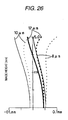
- the spherical aberration, astigmatism, distortion, and longitudinal aberration characteristics with respect to the wavelengths 8 ⁇ m, 10 ⁇ m, and 12 ⁇ m are illustrated in Figs. 25 to 27 and Figs. 28(a) to 28(e) .
- the infrared lens 1c according to Example 1-3 have configurations illustrated in Figs. 29 to 31 , and the lenses are configured that the f1/f is 1.00, the F value is 1.1, the maximum diameter is 30.0 mm, and the view angle is 16°.
- MTF characteristics with respect to wavelengths 8 ⁇ m, 10 ⁇ m, and 12 ⁇ m within view angles (0°, 5.0°, 6.0°, and 7.0°) in the configuration of Example 1-3 are illustrated in Figs. 32 to 38 .
- the spherical aberration, astigmatism, distortion, and longitudinal aberration characteristics with respect to the wavelengths 8 ⁇ m, 10 ⁇ m, and 12 ⁇ m are illustrated in Figs. 39 to 41 and Figs. 42(a) to 42(e) .
- the infrared lens 1d according to Example 1-4 have configurations illustrated in Figs. 43 to 45 , and the lenses are configured that the f1/f is 1.45, the F value is 1.0, the maximum diameter is 25.9 mm, and the view angle is 20°.
- the infrared lens 1e according to Example 1-5 have configurations illustrated in Figs. 46 to 48 , and the lenses are configured that the f1/f is 0.96, the F value is 1.1, the maximum diameter is 28.4 mm, and the view angle is 17°.
- Figs. 49(a) to 49(c) and Figs. 50(a) and 50(b) illustrate that MTF characteristics and the like of Examples 1-1, 1-2, 1-3, 1-4, and 1-5 are summarized in tables.
- the contents in the tables are inserted in the order of Examples 1-5, 1-3, 1-1, 1-2, and 1-4.
- the MTF values in the tables are denoted as the values at spatial frequency 20 lp/mm.
- MTF values in image heights within the view angle of the wavelength 12 ⁇ m, 10 ⁇ m, and 8 ⁇ m and averages of the MTF value in the range of 8 to 12 ⁇ m are noted on the lower side of the upper table.
- Examples 1-1, 1-2, 1-3, 1-4, and 1-5 will be estimated.
- the MTFs not less than 0.2 are obtained in the entire view angle and the entire wavelength.
- the infrared lens 2a including a first lens L1 (a first lens group), a second lens L2 (a second lens group), and a third lens L3 (a third lens group) which are made of zinc sulfide are arranged in this order from an object side as shown in Fig. 51 .
- the first lens L1 and the third lens L3 are positive meniscus lens of which convex surfaces are opposed to the object side, and the lenses have positive refractive power.
- the second lens L2 is a negative meniscus lens of which a convex surface is opposed to the image side, and the lens has positive refractive power.
- the first to third lens groups are configured by using lenses L1 to L3 so that one group has one lens, but the respective lens groups may be configured by using two lens or more, and the numbers of lenses corresponding to the respective lens groups may be configured to be different to each other.
- the entire lenses L1 to L3 are made of low-cost zinc sulfide, and the infrared lens 2a is configured by the two positive meniscus lens of which convex surfaces are opposed to the object side and one negative meniscus lens of which the convex surface is opposed to the image side. Therefore, it is possible to improve an imaging performance while minimizing the light loss at the time of transmission through the lenses by minimizing thicknesses of the respective lenses L1 to L3. It is also possible to provide the infrared lens 1a forming a bright image, and having a high imaging performance by using a configuration of low cost. Additionally, it is configured to be capable of contriving to minimize the light loss at the time of transmission through the lenses, by minimizing the thicknesses of the entire lenses relative to the known zinc sulfide lenses.
- a concave surface (the surface opposed to the image side, surface No. 2) of the first lens L1 is formed as a diffractive surface. Due to this, it is possible to effectively improve chromatic aberration which is a main issue in the infrared lens 2a. It is also possible to bring the most effective improvement result of the chromatic aberration, by forming the diffractive surface on the first lens L1 that a large refractive power is required and the chromatic aberration easily occurs. It is also possible to prevent attaching dust or the like to the diffractive surface caused by being exposed to external environment, by forming the diffractive surface on the surface which is the image side of the first lens L1.
- At least any one surface of the convex surface or the concave surface in the first lens L1 is formed as an aspheric surface.
- the aspheric surface is formed on the first lens L1 of which an aperture is large and the spherical aberration easily occurs, and thus it is possible to effectively improve the aberration.
- a degree of a shape change of the aspheric surface decreases relative to the case where the aspheric surface is formed on another lens and the mold fabrication and lens process are easy to perform.
- the concave surface (surface No. 2) of the first lens L1 the convex surface (surface No.
- the convex surface (surface No. 5) of the third lens L3, and the concave surface (surface No. 6) of the third lens L3 are formed as the aspheric surface, and the other lens surfaces are formed as a spherical surface.
- a F value of the infrared lens 2a is set by 0.8 to 1.2 or so.
- f12/f is set to be greater than 1.75, it is required to dispose the first lens L1 and the second lens L2 so as to be apart from each other. Therefore, skew rays propagate through a place apart from an optical axis of the first lens L1. Accordingly, astigmatism increases, and difficulty in correction of distortion is also increases therewith.
- the first to third lenses L1 to L3 which have such the configuration are formed as follows. Specifically, by using a mold formed in a lens shape and performing a heat press molding in a non-oxidizing atmosphere (for example, vacuum, inert gases such as Argon, or combination of them) on raw powder of zinc sulfide, the lenses L1 to L3 which are made of sintered bodies of polycrystalline zinc sulfide are obtained. In this way, it is possible to contrive a great reduction in material and processing cost of the infrared lens 2a, by fabricating the lenses L1 to L3 by a molding process using the zinc sulfide. It is also possible to perform mechanical processes such as a grinding and a polishing on the lenses L1 to L3 processed by the molding.
- a non-oxidizing atmosphere for example, vacuum, inert gases such as Argon, or combination of them
- the powder having an average particle diameter from 0.5 to 2 ⁇ m and purity 98% or more is available. It is desirable that a fabrication of a heat press molding is performed under the condition of temperature from 900 to 1100°C and pressure from 150 to 800 kg/cm 2 . Time for maintaining the pressure usually continues for from 0.05 to 1.5 hours, and the time is properly controlled by the combination between the conditions of temperature and pressure.
- the material and the thickness of the coating layer are appropriately selected in consideration of a using method, a place, and a situation of the infrared lens.
- a process of coating the lens surfaces by using an anti-reflection film may be performed (an AR coating process).
- a process of coating the lens surface (surface No. 1) located on the closest position relative to the object side of the first lens L1 by using an ultra-hard film such as DLC (diamond-like carbon) may be performed (a DLC coating process).
- the DLC coating process is remarkably effective when applying the infrared lens 2a according to Embodiment 2 to a night vision infrared camera for vehicle installation.
- the infrared camera for the night vision is installed under severe environment such as a normal vehicle's a front grill portion where the camera is exposed to a rainstorm and ballistic fragment while driving. Accordingly, since measures to resist the environment such as measures to prevent a scar of the lens and to prevent the lens from getting dirty are important, the DLC coating process is performed on the outermost lens surface (surface No. 1) which is exposed to external environment. In this manner, it can be easy to perform the measures.
- the infrared lens 2a having a predetermined optical performance by processing the heat press molding which uses the mold formed in a lens shape, it is required to employ a configuration suitable for the molding in the configurations such as the outer diameters or the thicknesses of the lenses L1 to L3.
- the thicknesses of the lenses L1 to L3 are required to secure molding capability (mechanical strength, processing accuracy, and the like) in the process of the heat press molding which is performed by using the lens shaped mold. Meanwhile, when the thicknesses increase, the light loss at the time of transmission through the lenses also increases. At that time, distribution of the compressive force occurs in a thickness direction of the lenses L1 to L3 in the process of the heat press molding, and thus distribution of the refractive index easily occurs.
- a combination includes the imaging device Id having pixel pitch 25 ⁇ m
- the imaging device Id a non-cooling thermal type imaging device such as a bolometer, a thermopile, and a SOI diode which have sensitivity of about 8 to 12 ⁇ m is used.
- the imaging device Id which has the number of pixels of 160 ⁇ 20 and 320 ⁇ 240 is used.
- narrow pixel pitches for example, 25 ⁇ m
- Examples 2-1, 2-2, and 2-3 fairly suitable as detailed example of Embodiment 2 will be described.
- Examples 2-4 and 2-5 will be introduced as two Comparative Examples relative to Examples 2-1, 2-2, and 2-3, and Examples 2-1, 2-2, and 2-3 and Examples 2-4 and 2-5 will be compared to each other.
- the f12/f is set by 1.25 in Example 2-1
- the f12/f is set by 1.75 in Example 2-2
- the f12/f is set by 1.05 in Example 2-3.
- the f12/f is set by 1.80 in Example 2-4
- the f12/f is set by 1.00 in Example 2-5.
- the infrared lens 2a according to Example 2-1 have configurations illustrated in the Figs. 51 to 53 , and the lenses are configured that the f12/f is 1.25, the F value is 0.89, the maximum diameter is 20.0 mm, and the view angle is 31° (the view angle is set in the combination case where the imaging device has a pixel pitch 25 ⁇ m and a pixel size 320 ⁇ 240).
- the aspheric surface shape (diffractive surface shape) of a second surface, a fourth surface, a fifth surface and a sixth surface shown in Fig. 53 is determined by substituting the parameter into the following expression (ditto below):
- Z y y 2 R 1 + 1 - ( 1 + K ) y 2 R 2 + A ⁇ 2 ⁇ y 2 + A ⁇ 4 ⁇ y 4 + A ⁇ 6 ⁇ y 6 + A ⁇ 8 ⁇ y 8 + ... + ⁇ y
- ⁇ y 1 N - 1 ⁇ mod ⁇ C ⁇ 1 ⁇ y 2 + C ⁇ 2 ⁇ y 4 , - ⁇
- the Z is a length (mm) of a perpendicular line down on the tangential surface in contact with the top of the aspheric surface from a point on the aspheric surface
- the y is a height (mm) from an optical axis
- the K is an eccentricity
- the R is a near-axis curvature radius
- the A2, A4, A6, and A8 are aspheric surface coefficients of second order, fourth order, sixth order, and eighth order.
- the N is a refractive index
- ⁇ is a value of a reference wavelength
- the C1 and C2 are diffractive surface coefficients.
- Figs. 54 to 60 Sagittal and tangential MTF characteristics with respect to wavelengths 8 ⁇ m, 10 ⁇ m, and 12 ⁇ m within view angles (0', 10.9°, 12.15°, and 15.34°) in the configuration of Example 2-1 are illustrated in Figs. 54 to 60 .
- the Ave. is a graph illustrating averages of the MTF values of 8 to 12 ⁇ m (ditto below).
- spherical aberration and astigmatism characteristics with respect to the wavelengths 8 ⁇ m, 10 ⁇ m, and 12 ⁇ m are illustrated in Figs. 61 and 62
- distortion characteristics are illustrated in Fig. 63
- Longitudinal aberration characteristics corresponding to the respective image heights in the view angle with respect to the wavelengths 8 ⁇ m, 10 ⁇ m, and 12 ⁇ m are illustrated in Figs. 64(a) to 64(e) (in the drawings, a left side and a right side corresponds to the tangential and the sagittal, respectively).
- the infrared lens 2b according to Example 2-2 have configurations illustrated in Figs. 65 to 67 , and the lenses are configured that the f12/f is 1.75, the F value is 1.08, the maximum diameter is 15.8 mm, and the view angle is 32°.
- MTF characteristics with respect to wavelengths 8 ⁇ m, 10 ⁇ m, and 12 ⁇ m within view angles (0°, 11.1°, 12.7°, and 16.2°) in the configuration of Example 2-2 are illustrated in Figs. 68 to 74 . Additionally, the spherical aberration, astigmatism, distortion, and longitudinal aberration characteristics with respect to the wavelengths 8 ⁇ m, 10 ⁇ m, and 12 ⁇ m are illustrated in Figs. 75 to 77 and 78(a) to 78(e) .
- the infrared lens 2c according to Example 2-3 have configurations illustrated in Figs. 79 to 81 , and the lenses are configured that the f12/f is 1.05, the F value is 1.01, the maximum diameter is 17.2 mm, and the view angle is 32°.
- MTF characteristics with respect to wavelengths 8 ⁇ m, 10 ⁇ m, and 12 ⁇ m within view angles (0°, 11.0°, 12.5°, and 16.0°) in the configuration of Example 2-3 are illustrated in Figs. 82 to 88 . Additionally, the spherical aberration, astigmatism, distortion, and longitudinal aberration characteristics with respect to the wavelengths 8 ⁇ m, 10 ⁇ m, and 12 ⁇ m are illustrated in Figs. 89 to 91 and 92(a) to 92(e) .
- the infrared lens 2d according to Example 2-4 have configurations illustrated in Figs. 93 to 95 , and the lenses are configured that the f12/f is 1.80, the F value is 1.05, the maximum diameter is 15.8 mm, and the view angle is 33°.
- the infrared lens 2e according to Example 2-5 have configurations illustrated in Figs. 96 to 98 , and the lenses are configured that the f12/f is 1.00, the F value is 1.01, the maximum diameter is 17.2 mm, and the view angle is 32°.
- Figs. 99(a) to 99(c) , and Figs. 100(d) and 100(e) illustrate that MTF characteristics and the like of Examples 2-1 to 2-5 are summarized in tables.
- the contents in the tables are inserted in the order of Examples 2-5, 2-3, 2-1, 2-2, and 2-4.
- the MTF values in the tables are denoted as the values at spatial frequency 20 lp/mm. Additionally, in the tables, MTF values in image heights within the view angle of the wavelength 12 ⁇ m, 10 ⁇ m, and 8 ⁇ m and averages of the MTF value in the range of 8 to 12 ⁇ m are noted on the lower side of the upper table.
- Examples 2-1 to 2-5 will be estimated.
- the MTFs not less than 0.2 are obtained in the entire view angle and the entire wavelength.
- the infrared lens 2a including a first lens L1 (a first lens group) and a second lens L2 (a third lens group) which are made of zinc sulfide are arranged in this order from an object side as shown in Fig. 101 .
- the first lens L1 and the second lens L2 are positive meniscus lens of which convex surfaces are opposed to the object side, and the lenses have positive refractive power.
- the first and the second lens groups are configured by using lenses L1 and L2 so that one group has one lens, but the respective lens groups may be configured by using two lens or more, and the numbers of lenses corresponding to the respective lens groups may be configured to be different to each other.
- the entire lenses L1 and L2 are made of low-cost zinc sulfide, and the infrared lens 3a are configured by the two positive meniscus lens of which convex surfaces are opposed to the object side. Therefore, it is possible to improve an imaging performance while minimizing the light loss at the time of transmission through the lenses by minimizing thicknesses of the respective lenses L1 and L2. It is also possible to provide the infrared lens 3a forming a bright image, and having a high imaging performance by using a configuration of low cost. Additionally, it is configured to be capable of contriving to minimize the light loss at the time of transmission through the lenses, by minimizing the thicknesses of the entire lenses relative to the known zinc sulfide lenses.
- a concave surface (the surface opposed to the image side, surface No. 2) of the first lens L1 is formed as a diffractive surface. Due to this, it is possible to effectively improve chromatic aberration which is a main issue in the infrared lens 3a. It is also possible to bring the most effective improvement result of the chromatic aberration, by forming the diffractive surface on the first lens L1 that a large refractive power is required and the chromatic aberration easily occurs. It is also possible to prevent attaching dust or the like to the diffractive surface caused by being exposed to external environment, by forming the diffractive surface on the surface which is the image side of the first lens L1.
- At least any one surface of the convex surface or the concave surface in the first lens L1 is formed as an aspheric surface.
- the aspheric surface is formed on the first lens L1 of which an aperture is large and the spherical aberration easily occurs, and thus it is possible to effectively improve the aberration.
- a degree of a shape change of the aspheric surface decreases relative to the case where the aspheric surface is formed on another lens and the mold fabrication and lens process are easy to perform.
- the convex surface (surface No. 1) of the first lens L1 the concave surface (surface No.
- the convex surface (surface No. 3) of the second lens L2 and the concave surface (surface No. 4) of the second lens L2 are formed as the aspheric surface, and the other lens surfaces are formed as a spherical surface.
- An F value of the infrared lens 3a is set by 0.8 to 1.2 or so.
- f1/f is set to be greater than 1.5, it is required to dispose the first lens L1 and the second lens L2 so as to be apart from each other. Therefore, skew rays propagate through a place apart from an optical axis of the first lens L1. Accordingly, astigmatism increases, and difficulty in correction of distortion is also increases therewith.
- the first and second lenses L1 and L2 which have such the configuration are formed as follows. Specifically, by using a mold formed in a lens shape and performing a heat press molding in a non-oxidizing atmosphere (for Example, vacuum, inert gases such as Argon, or combination of them) on raw powder of zinc sulfide, the lenses L1 and L2 which are made of sintered bodies of polycrystalline zinc sulfide are obtained. In this way, it is possible to contrive a great reduction in material and processing cost of the infrared lens 3a, by fabricating the lenses L1 and L2 by a molding process using the zinc sulfide. It is also possible to perform mechanical processes such as a grinding and a polishing on the lenses L1 and L2 processed by the molding.
- a non-oxidizing atmosphere for Example, vacuum, inert gases such as Argon, or combination of them
- the powder having an average particle diameter from 0.5 to 2 ⁇ m and purity 98% or more is available. It is desirable that a fabrication of a heat press molding is performed under the condition of temperature from 900 to 1100°C and pressure from 150 to 800 kg/cm 2 . Time for maintaining the pressure usually continues for from 0.05 to 1.5 hours, and the time is properly controlled by the combination between the conditions of temperature and pressure.
- the polycrystalline zinc sulfide lens it is one of effective methods for the polycrystalline zinc sulfide lens to perform a coating for improving the transmittance characteristic or protecting the surface thereof from external affections.
- the material and the thickness of the coating layer are appropriately selected in consideration of a using method, a place, and a situation of the infrared lens.
- a process of coating the lens surfaces by using an anti-reflection film may be performed (an AR coating process).
- an ultra-hard film such as DLC (diamond-like carbon)
- the DLC coating process is remarkably effective when applying the infrared lens 3a according to Embodiment 2 to the infrared camera for a night vision installed in a vehicle.
- the infrared camera for the night vision is installed under severe environment such as a normal vehicle's a front grill portion where the camera is exposed to a rainstorm and ballistic fragment while driving. Accordingly, since measures to resist the environment such as measures to prevent a scar of the lens and to prevent the lens from getting dirty are important, the DLC coating process is performed on the outermost lens surface (surface No. 1) which is exposed to external environment. In this manner, it can be easy to perform the measures.
- the infrared lens 3a having a predetermined optical performance by processing the heat press molding which uses the mold formed in a lens shape, it is required to employ a configuration suitable for the molding in the configurations such as the outer diameters or the thicknesses of the lenses L1 and L2.
- the thicknesses of the lenses L1 and L2 are required to secure molding capability (mechanical strength, processing accuracy, and the like) in the process of the heat press molding which is performed by using the lens shaped mold. Meanwhile, when the thicknesses increase, the light loss at the time of transmission through the lenses also increases. At that time, distribution of the compressive force occurs in a thickness direction of the lenses L1 and L2 in the process of the heat press molding, and thus distribution of the refractive index easily occurs.
- a combination includes the imaging device Id having pixel pitch 25 ⁇ m, in terms of the thicknesses of the lenses L1 and L2, it is desirable to set a central thickness Tm and a peripheral thickness Te so as to satisfy the following relational expressions: 1.5 mm ⁇ Tm ⁇ 8.0 mm and 1.0 mm ⁇ Te ⁇ 8.0 mm . Due to this, by securing the molding capability in the process of the heat press molding which is performed by using the lens shaped mold, it is possible to embody the infrared lens 3a of which the thicknesses are thin and the light loss at the time of transmission through the lenses is minimized.
- the distribution of the compressive force occurs in the thickness direction of the lenses in the process of the heat press molding, and thus it is also possible to prevent the problem that the distribution of the refractive index occurs in the thickness direction.
- the imaging device Id a non-cooling thermal type imaging device such as a bolometer, a thermopile, and a SOI diode which have sensitivity of about 8 to 12 ⁇ m is used.
- the imaging device Id which has the number of pixels of 160 ⁇ 120 and 320 ⁇ 240 is used.
- the imaging device Id which has narrow pixel pitches for Example, 25 ⁇ m
- Examples 3-4 and 3-5 will be introduced as two Comparative Examples relative to Examples 3-1, 3-2, and 3-3, and Examples 3-1, 3-2, and 3-3 and Examples 3-4 and 3-5 will be compared to each other.
- the f1/f is set by 1.37 in Example 3-1
- the f1/f is set by 1.50 in Example 3-2
- the f1/f is set by 1.25 in Example 3-3.
- the f1/f is set by 1.55 in Example 3-4
- the f1/f is set by 1.20 in Example 3-5.
- the infrared lens 3a according to Example 3-1 have configurations illustrated in the Figs. 101 to 103 , and the lenses are configured that the f1/f is 1.37, the F value is 1.01, the maximum diameter is 18.0 mm, and the view angle is 30° (the view angle is set in the combination case where the imaging device has a pixel pitch 25 ⁇ m and a pixel size 320 ⁇ 240).
- the aspheric surface shape (diffractive surface shape) of a first surface, a second surface, a third surface and a fourth surface shown in Fig. 53 is determined by substituting the parameter into the following expression (ditto below):
- Z y y 2 R 1 + 1 - ( 1 + K ) y 2 R 2 + A ⁇ 2 ⁇ y 2 + A ⁇ 4 ⁇ y 4 + A ⁇ 6 ⁇ y 6 + A ⁇ 8 ⁇ y 8 + ... + ⁇ y
- ⁇ y 1 N - 1 ⁇ mod ⁇ C ⁇ 1 ⁇ y 2 + C ⁇ 2 ⁇ y 4 , - ⁇
- the Z is a length (mm) of a perpendicular line down on the tangential surface in contact with the top of the aspheric surface from a point on the aspheric surface
- the y is a height (mm) from an optical axis
- the K is an eccentricity
- the R is a near-axis curvature radius
- the A2, A4, A6, and A8 are aspheric surface coefficients of second order, fourth order, sixth order, and eighth order.
- the N is a refractive index
- ⁇ is a value of a reference wavelength
- the C1 and C2 are diffractive surface coefficients.
- Figs. 104 to 110 Sagittal and tangential MTF characteristics with respect to wavelengths 8 ⁇ m, 10 ⁇ m, and 12 ⁇ m within view angles (0°, 10.5°, 12.0°, and 15.0°) in the configuration of Example 3-1 are illustrated in Figs. 104 to 110 .
- the Ave. is a graph illustrating averages of the MTF values of 8 to 12 ⁇ m (ditto below).
- spherical aberration and astigmatism characteristics with respect to the wavelengths 8 ⁇ m, 10 ⁇ m, and 12 ⁇ m are illustrated in Figs. 111 and 112
- distortion characteristics are illustrated in Fig. 113
- Longitudinal aberration characteristics corresponding to the respective image heights in the view angle with respect to the wavelengths 8 ⁇ m, 10 ⁇ m, and 12 ⁇ m are illustrated in Figs. 114(a) to 114(e) (in the drawings, a left side and a right side corresponds to the tangential and the sagittal, respectively).
- the infrared lens 3b according to Example 3-2 have configurations illustrated in Figs. 115 to 117 , and the lenses are configured that the f1/f is 1.50, the F value is 1.09, the maximum diameter is 16.6 mm, and the view angle is 30°.
- MTF characteristics with respect to wavelengths 8 ⁇ m, 10 ⁇ m, and 12 ⁇ m within view angles (0°, 10.5°, 12.0°, and 15.0°) in the configuration of Example 3-2 are illustrated in Figs. 118 to 124 . Additionally, the spherical aberration, astigmatism, distortion, and longitudinal aberration characteristics with respect to the wavelengths 8 ⁇ m, 10 ⁇ m, and 12 ⁇ m are illustrated in Figs. 125 to 127 and 128(a) to 128(e) .
- the infrared lens 3c according to Example 3-3 have configurations illustrated in Figs. 129 to 131 , and the lenses are configured that the f1/f is 1.25, the F value is 1.05, the maximum diameter is 17.3 mm, and the view angle is 30°.
- MTF characteristics with respect to wavelengths 8 ⁇ m, 10 ⁇ m, and 12 ⁇ m within view angles (0°, 10.5°, 12.0°, and 15.0°) in the configuration of Example 3-3 are illustrated in Figs. 132 to 138 . Additionally, the spherical aberration, astigmatism, distortion, and longitudinal aberration characteristics with respect to the wavelengths 8 ⁇ m, 10 ⁇ m, and 12 ⁇ m are illustrated in Figs. 139 to 141 and 142(a) to 142(e) .
- the infrared lens 3d according to Example 3-4 have configurations illustrated in Figs. 143 to 145 , and the lenses are configured that the f1/f is 1.55, the F value is 1.10, the maximum diameter is 16.4 mm, and the view angle is 30°.
- the infrared lens 3e according to Example 3-5 have configurations illustrated in Figs. 146 to 148 , and the lenses are configured that the f1/f is 1.20, the F value is 1.04, the maximum diameter is 17.4 mm, and the view angle is 30°.
- Figs. 149(a) to 149(c) , and Figs. 150(d) and 1500(e) illustrate that MTF characteristics and the like of Examples 3-1 to 3-5 are summarized in tables.
- the contents in the tables are inserted in the order of Examples 3-5, 3-3, 3-1, 3-2, and 3-4.
- the MTF values in the tables are denoted as the values at spatial frequency 20 lp/mm. Additionally, in the tables, MTF values in image heights within the view angle of the wavelength 12 ⁇ m, 10 ⁇ m, and 8 ⁇ m and averages of the MTF value in the range of 8 to 12 ⁇ m are noted on the lower side of the upper table.
- Examples 3-1 to 3-5 will be estimated.
- the value of f1/f satisfies the condition of the relational expression 2 in the MTF characteristics illustrated in Figs. 149(a) to 149(c) and Figs. 150(d) and 150(e)
- the MTFs not less than 0.2 are obtained in the entire view angle and the entire wavelength.
- the night vision includes an infrared camera 21 disposed on a front end and the like of a vehicle, a display unit 23 having a liquid crystal display and the like which are disposed on a position visible from a driver's seat in the vehicle, and a controller 25 performing picture processes (i.e.
- the infrared camera 21 includes the aforementioned infrared lens 1a to 1c, 2a to 2c, or 3a to 3c, an infrared transmission window Fi, and an imaging device Id, and the camera performs taking an infrared picture in front of the vehicle by receiving infrared rays which are radiated from objects (i.e. human and the like) in front of the vehicle at night and the like.
- the night vision is configured by using the infrared lens 1a to 1c, 2a to 2c, or 3a to 3c according to Embodiments 1, 2, or 3, thereby enabling to obtain pictures which have high resolution, high brightness, and high contrast required to extract the human images from the infrared picture, by performing the picture processes by the controller 25. Thanks to this, for example, even though the picture is taken at night time or the picture has bright images caused by bright scene of summer season (in the images in summer season, brightness differences between a background and people such as pedestrians decrease), it is possible to recognize humans in the picture by performing the picture process.
- the infrared lens 1a to 1c, 2a to 2c, and 3a to 3c are suitable for a decrease in size, it is possible for the infrared camera to decrease in size, and it is also possible to easily configure the night vision suitable for vehicle installation.
Landscapes
- Physics & Mathematics (AREA)
- General Physics & Mathematics (AREA)
- Optics & Photonics (AREA)
- Health & Medical Sciences (AREA)
- Toxicology (AREA)
- Lenses (AREA)
Priority Applications (1)
| Application Number | Priority Date | Filing Date | Title |
|---|---|---|---|
| EP10165518A EP2226666A1 (fr) | 2006-01-30 | 2006-11-07 | Lentille infrarouge, caméra infrarouge et vision nocturne |
Applications Claiming Priority (3)
| Application Number | Priority Date | Filing Date | Title |
|---|---|---|---|
| JP2006020411A JP4631728B2 (ja) | 2006-01-30 | 2006-01-30 | 赤外線レンズ、赤外線カメラ及びナイトビジョン |
| JP2006065401A JP4631753B2 (ja) | 2006-03-10 | 2006-03-10 | 赤外線レンズ及び赤外線カメラ |
| PCT/JP2006/322195 WO2007086178A1 (fr) | 2006-01-30 | 2006-11-07 | Objectif à infrarouge, appareil de prise de vue à infrarouge et vision nocturne |
Publications (2)
| Publication Number | Publication Date |
|---|---|
| EP1980888A1 true EP1980888A1 (fr) | 2008-10-15 |
| EP1980888A4 EP1980888A4 (fr) | 2010-03-17 |
Family
ID=38308986
Family Applications (2)
| Application Number | Title | Priority Date | Filing Date |
|---|---|---|---|
| EP10165518A Withdrawn EP2226666A1 (fr) | 2006-01-30 | 2006-11-07 | Lentille infrarouge, caméra infrarouge et vision nocturne |
| EP06823099A Withdrawn EP1980888A4 (fr) | 2006-01-30 | 2006-11-07 | Objectif à infrarouge, appareil de prise de vue à infrarouge et vision nocturne |
Family Applications Before (1)
| Application Number | Title | Priority Date | Filing Date |
|---|---|---|---|
| EP10165518A Withdrawn EP2226666A1 (fr) | 2006-01-30 | 2006-11-07 | Lentille infrarouge, caméra infrarouge et vision nocturne |
Country Status (4)
| Country | Link |
|---|---|
| US (3) | US7738169B2 (fr) |
| EP (2) | EP2226666A1 (fr) |
| KR (2) | KR100955975B1 (fr) |
| WO (1) | WO2007086178A1 (fr) |
Cited By (1)
| Publication number | Priority date | Publication date | Assignee | Title |
|---|---|---|---|---|
| EP2034345A3 (fr) * | 2007-09-10 | 2010-05-26 | Sumitomo Electric Industries, Ltd. | Objectif de caméra à infrarouge lointain, unité d'objectif et appareil d'imagerie |
Families Citing this family (16)
| Publication number | Priority date | Publication date | Assignee | Title |
|---|---|---|---|---|
| EP2226666A1 (fr) | 2006-01-30 | 2010-09-08 | Sumitomo Electric Industries, Ltd. | Lentille infrarouge, caméra infrarouge et vision nocturne |
| JP2009063942A (ja) | 2007-09-10 | 2009-03-26 | Sumitomo Electric Ind Ltd | 遠赤外線カメラ用レンズ、レンズユニット及び撮像装置 |
| JP2012103461A (ja) * | 2010-11-10 | 2012-05-31 | Topcon Corp | 赤外線光学系 |
| KR101293217B1 (ko) * | 2011-10-21 | 2013-08-05 | 주식회사 소모홀딩스엔테크놀러지 | 고해상도 원적외선 카메라용 렌즈 유니트 |
| EP2804036A4 (fr) * | 2012-01-13 | 2015-09-16 | Olympus Medical Systems Corp | Composant d'extrémité d'endoscope, et endoscope |
| KR101494439B1 (ko) * | 2013-09-23 | 2015-02-24 | 한국세라믹기술원 | 적외선 렌즈 및 그 제조 방법 |
| CN104090350A (zh) * | 2014-08-04 | 2014-10-08 | 江苏卡罗卡国际动漫城有限公司 | 一种长波红外物镜 |
| US20170139188A1 (en) * | 2014-08-07 | 2017-05-18 | Han's Laser Technology Industry Group Co., Ltd. | Far Infrared Imaging Lens Set, Objective Lens And Fire Source Detector |
| JP6391807B2 (ja) * | 2014-08-07 | 2018-09-19 | ハンズ レーザー テクノロジー インダストリー グループ カンパニー リミテッド | 遠赤外線撮像レンズ組、対物レンズおよび探知器 |
| JP6798161B2 (ja) * | 2016-03-15 | 2020-12-09 | 住友電気工業株式会社 | 赤外線レンズモジュール |
| KR102342322B1 (ko) | 2017-07-21 | 2021-12-23 | 한국광기술원 | ta-C 및 Y2O3 코팅 박막층을 구비한 하이브리드 적외선 광학렌즈 |
| KR20190010222A (ko) | 2017-07-21 | 2019-01-30 | 한국광기술원 | YbF3 박막층을 구비한 원적외선 광학렌즈 |
| TWI703367B (zh) * | 2018-02-08 | 2020-09-01 | 先進光電科技股份有限公司 | 光學成像系統 |
| CN111853699B (zh) * | 2020-08-28 | 2021-02-12 | 广东烨嘉光电科技股份有限公司 | 一种大孔径的三片式透镜光学镜头 |
| KR102500286B1 (ko) | 2021-02-26 | 2023-02-15 | 한국광기술원 | ta-C 및 Y2O3 코팅 박막층을 구비한 하이브리드 적외선 광학렌즈 |
| CN113176653B (zh) * | 2021-04-28 | 2022-07-01 | 天津欧菲光电有限公司 | 光学系统、镜头模组和电子设备 |
Citations (5)
| Publication number | Priority date | Publication date | Assignee | Title |
|---|---|---|---|---|
| US3363962A (en) * | 1964-05-11 | 1968-01-16 | Westinghouse Electric Corp | Infrared optical system comprising three lens elements |
| EP0544174A1 (fr) * | 1991-11-25 | 1993-06-02 | Hughes Aircraft Company | Component optique avec des éléments réfractives et diffractives pour obtenir une valeur Abbé désirée |
| EP0950904A1 (fr) * | 1998-04-14 | 1999-10-20 | Sumitomo Electric Industries, Ltd. | Elément optique, compact de sulfure de zinc fritté et procédé de fabrication de celui-ci |
| US6090456A (en) * | 1997-05-03 | 2000-07-18 | The United States Of America As Represented By The Secretary Of The Air Force | Process for large area deposition of diamond-like carbon films |
| JP2003295052A (ja) * | 2002-03-29 | 2003-10-15 | Fuji Photo Optical Co Ltd | 赤外線レンズ |
Family Cites Families (28)
| Publication number | Priority date | Publication date | Assignee | Title |
|---|---|---|---|---|
| US3160700A (en) * | 1961-08-18 | 1964-12-08 | John R Snyder | Infrared optical system |
| US3727345A (en) * | 1970-10-28 | 1973-04-17 | N Smith | Method of protecting plants and stimulating their growth |
| US3825315A (en) * | 1973-01-29 | 1974-07-23 | R Altman | Zoom lens optical system for infrared wavelengths |
| GB1478115A (en) * | 1974-02-15 | 1977-06-29 | Pilkington Perkin Elmer Ltd | Infra-red lenses |
| GB1462892A (en) * | 1974-10-02 | 1977-01-26 | Rank Organisation Ltd | Lenses |
| US4380363A (en) * | 1981-04-03 | 1983-04-19 | Rockwell International Corporation | Four element infrared objective lens |
| CH658731A5 (de) * | 1982-06-25 | 1986-11-28 | Kern & Co Ag | Lichtstarkes objektiv fuer waermestrahlung. |
| US4486286A (en) * | 1982-09-28 | 1984-12-04 | Nerken Research Corp. | Method of depositing a carbon film on a substrate and products obtained thereby |
| US4549960A (en) * | 1983-07-07 | 1985-10-29 | Hoppe Gerald W | System for conditioning grain and maintaining same |
| JPS62109014A (ja) | 1985-11-08 | 1987-05-20 | Ricoh Co Ltd | 赤外線用レンズ |
| DE4234721C2 (de) * | 1991-10-16 | 1995-10-19 | Bodenseewerk Geraetetech | Dreilinsenobjektiv |
| DE4331735C1 (de) * | 1993-09-17 | 1995-03-02 | Steinheil Optronik Gmbh | Objektiv |
| JP3326641B2 (ja) | 1993-10-19 | 2002-09-24 | 株式会社ニコン | 赤外線用光学系 |
| US6423969B1 (en) * | 1994-09-22 | 2002-07-23 | Lockheed Martin Corporation | Dual infrared band objective lens |
| US5940224A (en) * | 1998-03-16 | 1999-08-17 | Nikon Corporation | Wide band infrared camera lens systems |
| GB9809736D0 (en) * | 1998-05-08 | 1998-07-08 | Pilkington Perkin Elmer Ltd | Objective lens system |
| IL124598A (en) * | 1998-05-21 | 2001-10-31 | Ophir Optronics Ltd | Precision double-sided aspheric elements |
| US6456261B1 (en) * | 1998-11-23 | 2002-09-24 | Evan Y. W. Zhang | Head/helmet mounted passive and active infrared imaging system with/without parallax |
| JP2001033689A (ja) * | 1999-07-26 | 2001-02-09 | Fuji Photo Optical Co Ltd | 明るく広角な赤外線レンズ |
| WO2002005013A2 (fr) * | 2000-07-10 | 2002-01-17 | Ophir Optronics Ltd. | Procede et systeme d'assistance a la visibilite reduite |
| JP4449456B2 (ja) * | 2001-12-26 | 2010-04-14 | 住友電気工業株式会社 | セラミックス光学部品の製造方法 |
| US7042656B2 (en) | 2003-05-01 | 2006-05-09 | Raytheon Company | Compact wide-field-of-view imaging optical system |
| US20040263978A1 (en) * | 2003-06-18 | 2004-12-30 | Chipper Robert B. | Method and apparatus for forming an image using only diffractive optics |
| US6989537B2 (en) * | 2003-11-18 | 2006-01-24 | Raytheon Company | Compact inverse-telephoto infrared imaging optical system |
| JP2006197015A (ja) * | 2005-01-11 | 2006-07-27 | Sumitomo Electric Ind Ltd | 車両用暗視撮像装置 |
| EP2226666A1 (fr) * | 2006-01-30 | 2010-09-08 | Sumitomo Electric Industries, Ltd. | Lentille infrarouge, caméra infrarouge et vision nocturne |
| JP2009063941A (ja) * | 2007-09-10 | 2009-03-26 | Sumitomo Electric Ind Ltd | 遠赤外線カメラ用レンズ、レンズユニット及び撮像装置 |
| JP2009063942A (ja) * | 2007-09-10 | 2009-03-26 | Sumitomo Electric Ind Ltd | 遠赤外線カメラ用レンズ、レンズユニット及び撮像装置 |
-
2006
- 2006-11-07 EP EP10165518A patent/EP2226666A1/fr not_active Withdrawn
- 2006-11-07 WO PCT/JP2006/322195 patent/WO2007086178A1/fr active Application Filing
- 2006-11-07 EP EP06823099A patent/EP1980888A4/fr not_active Withdrawn
- 2006-11-07 KR KR1020077025096A patent/KR100955975B1/ko not_active IP Right Cessation
- 2006-11-07 KR KR1020107000970A patent/KR100960776B1/ko not_active IP Right Cessation
- 2006-11-07 US US11/919,754 patent/US7738169B2/en active Active
-
2010
- 2010-01-14 US US12/687,622 patent/US7911688B2/en not_active Expired - Fee Related
-
2011
- 2011-01-31 US US13/017,755 patent/US8085465B2/en active Active
Patent Citations (5)
| Publication number | Priority date | Publication date | Assignee | Title |
|---|---|---|---|---|
| US3363962A (en) * | 1964-05-11 | 1968-01-16 | Westinghouse Electric Corp | Infrared optical system comprising three lens elements |
| EP0544174A1 (fr) * | 1991-11-25 | 1993-06-02 | Hughes Aircraft Company | Component optique avec des éléments réfractives et diffractives pour obtenir une valeur Abbé désirée |
| US6090456A (en) * | 1997-05-03 | 2000-07-18 | The United States Of America As Represented By The Secretary Of The Air Force | Process for large area deposition of diamond-like carbon films |
| EP0950904A1 (fr) * | 1998-04-14 | 1999-10-20 | Sumitomo Electric Industries, Ltd. | Elément optique, compact de sulfure de zinc fritté et procédé de fabrication de celui-ci |
| JP2003295052A (ja) * | 2002-03-29 | 2003-10-15 | Fuji Photo Optical Co Ltd | 赤外線レンズ |
Non-Patent Citations (1)
| Title |
|---|
| See also references of WO2007086178A1 * |
Cited By (2)
| Publication number | Priority date | Publication date | Assignee | Title |
|---|---|---|---|---|
| EP2034345A3 (fr) * | 2007-09-10 | 2010-05-26 | Sumitomo Electric Industries, Ltd. | Objectif de caméra à infrarouge lointain, unité d'objectif et appareil d'imagerie |
| US7835071B2 (en) | 2007-09-10 | 2010-11-16 | Sumitomo Electric Industries, Ltd. | Far-infrared camera lens, lens unit, and imaging apparatus |
Also Published As
| Publication number | Publication date |
|---|---|
| US8085465B2 (en) | 2011-12-27 |
| US7911688B2 (en) | 2011-03-22 |
| KR20100012102A (ko) | 2010-02-05 |
| US7738169B2 (en) | 2010-06-15 |
| KR100960776B1 (ko) | 2010-06-01 |
| EP2226666A1 (fr) | 2010-09-08 |
| EP1980888A4 (fr) | 2010-03-17 |
| US20110164142A1 (en) | 2011-07-07 |
| KR100955975B1 (ko) | 2010-05-04 |
| US20100187418A1 (en) | 2010-07-29 |
| US20090027766A1 (en) | 2009-01-29 |
| WO2007086178A1 (fr) | 2007-08-02 |
| KR20080015400A (ko) | 2008-02-19 |
Similar Documents
| Publication | Publication Date | Title |
|---|---|---|
| EP1980888A1 (fr) | Objectif à infrarouge, appareil de prise de vue à infrarouge et vision nocturne | |
| JP4631753B2 (ja) | 赤外線レンズ及び赤外線カメラ | |
| JP4631728B2 (ja) | 赤外線レンズ、赤外線カメラ及びナイトビジョン | |
| JP3982554B2 (ja) | 赤外線ズームレンズ及び赤外線カメラ | |
| US20200257079A1 (en) | Optical lens, imaging module and vehicle camera | |
| JP5617642B2 (ja) | 赤外線光学系、赤外線撮像装置 | |
| EP3940442A1 (fr) | Lentille d'imagerie optique et dispositif d'imagerie | |
| US20160077313A1 (en) | Wide angle lens | |
| JP6695995B2 (ja) | 撮像レンズ系及び撮像装置 | |
| US20200278517A1 (en) | Optical imaging lens assembly, image capturing unit and electronic device | |
| US10175459B2 (en) | Optical imaging system | |
| JP2007264649A (ja) | 赤外線ズームレンズ及び赤外線カメラ | |
| JP2008268281A (ja) | 赤外線レンズ群、赤外線カメラ、夜間運転支援システム | |
| CN112882209B (zh) | 广角镜头及成像设备 | |
| CN214751064U (zh) | 光学成像系统、取像模组、电子设备和汽车 | |
| WO2019142770A1 (fr) | Unité de lentille infrarouge et caméra infrarouge | |
| JP2006527866A (ja) | 回折光学系のみを使用して画像を形成する方法および装置 | |
| CN210051955U (zh) | 取像模组、电子装置及汽车 | |
| CN113325556A (zh) | 广角镜头 | |
| CN111999851A (zh) | 取像模组、电子装置及汽车 |
Legal Events
| Date | Code | Title | Description |
|---|---|---|---|
| PUAI | Public reference made under article 153(3) epc to a published international application that has entered the european phase |
Free format text: ORIGINAL CODE: 0009012 |
|
| 17P | Request for examination filed |
Effective date: 20071030 |
|
| AK | Designated contracting states |
Kind code of ref document: A1 Designated state(s): DE FR GB SE |
|
| RBV | Designated contracting states (corrected) |
Designated state(s): DE FR GB SE |
|
| A4 | Supplementary search report drawn up and despatched |
Effective date: 20100215 |
|
| DAX | Request for extension of the european patent (deleted) | ||
| STAA | Information on the status of an ep patent application or granted ep patent |
Free format text: STATUS: THE APPLICATION HAS BEEN WITHDRAWN |
|
| 18W | Application withdrawn |
Effective date: 20120504 |